JP4953219B2 - Fuel cell life prediction apparatus and fuel cell system - Google Patents
Fuel cell life prediction apparatus and fuel cell system Download PDFInfo
- Publication number
- JP4953219B2 JP4953219B2 JP2004333672A JP2004333672A JP4953219B2 JP 4953219 B2 JP4953219 B2 JP 4953219B2 JP 2004333672 A JP2004333672 A JP 2004333672A JP 2004333672 A JP2004333672 A JP 2004333672A JP 4953219 B2 JP4953219 B2 JP 4953219B2
- Authority
- JP
- Japan
- Prior art keywords
- fuel cell
- life
- polymer electrolyte
- electrolyte membrane
- amount
- Prior art date
- Legal status (The legal status is an assumption and is not a legal conclusion. Google has not performed a legal analysis and makes no representation as to the accuracy of the status listed.)
- Expired - Fee Related
Links
Images


Classifications
-
- Y—GENERAL TAGGING OF NEW TECHNOLOGICAL DEVELOPMENTS; GENERAL TAGGING OF CROSS-SECTIONAL TECHNOLOGIES SPANNING OVER SEVERAL SECTIONS OF THE IPC; TECHNICAL SUBJECTS COVERED BY FORMER USPC CROSS-REFERENCE ART COLLECTIONS [XRACs] AND DIGESTS
- Y02—TECHNOLOGIES OR APPLICATIONS FOR MITIGATION OR ADAPTATION AGAINST CLIMATE CHANGE
- Y02E—REDUCTION OF GREENHOUSE GAS [GHG] EMISSIONS, RELATED TO ENERGY GENERATION, TRANSMISSION OR DISTRIBUTION
- Y02E60/00—Enabling technologies; Technologies with a potential or indirect contribution to GHG emissions mitigation
- Y02E60/30—Hydrogen technology
- Y02E60/50—Fuel cells
Description
本発明は、携帯機器用電源、ポータブル電源、電気自動車用電源、家庭内コージェネシステム等に使用される燃料電池、特に高分子電解質型燃料電池の寿命予測装置、及び燃料電池システムに関するものである。 The present invention relates to a fuel cell used for a power source for portable devices, a portable power source, a power source for electric vehicles, a domestic cogeneration system, and the like, in particular, a life prediction device for a polymer electrolyte fuel cell, and a fuel cell system.
高分子電解質型燃料電池は、水素などの燃料ガスと空気などの酸化剤ガスをガス拡散電極によって電気化学的に反応させ、発電を行うものである。図13に、このような従来の高分子電解質燃料電池の一般的な構成を示す概略断面図を示す。 A polymer electrolyte fuel cell performs power generation by allowing a fuel gas such as hydrogen and an oxidant gas such as air to react electrochemically with a gas diffusion electrode. FIG. 13 is a schematic cross-sectional view showing a general configuration of such a conventional polymer electrolyte fuel cell.
図13に示すように、高分子電解質型燃料電池120は、ガス拡散層101、触媒反応層102、高分子電解質膜103、セパレータ板104、ガス流路105、冷却水流路107、電極109、MEA110、ガスシール材113、及びOリング114等から構成されている。
As shown in FIG. 13, the polymer
すなわち、水素イオンを選択的に輸送する高分子電解質膜103の両面には、白金系の金属触媒を担持したカーボン粉末を主成分とする触媒反応層102が密着して配置されている。さらに触媒反応層102の外面に、ガス通気性と導電性を兼ね備えた一対のガス拡散層101が密着して配置されている。このガス拡散層101と触媒反応層102により電極109が構成されている。
That is, the
電極109の外側には、電極109と高分子電解質膜103とで形成した電極電解質接合体(以下、MEAとする)110が機械的に固定されている。そして、隣接するMEA110同士が互いに電気的に直列に接続されている。さらに電極109に反応ガスを供給しかつ反応により発生したガスや余剰のガスを運び去るためのガス流路105を一方の面に形成した導電性セパレータ板104が配置されている。
An electrode electrolyte assembly (hereinafter referred to as MEA) 110 formed of the
ガス流路105は、セパレータ板104と別に設けることもできるが、セパレータ板104の表面に溝を設けてガス流路105とする方式が一般的である。セパレータ板104の他方の面には、電池温度を一定に保つための冷却水を循環させる冷却水流路107が設けられている。冷却水流路107に冷却水を循環させることにより、反応により発生した熱エネルギーは、温水などの形で利用することができる。
The
また、水素や空気が電池外にリークしたり、互いに混合したりしないように、さらには冷却水が電池外にリークしないように、電極109の周囲には高分子電解質膜103を挟んでガスシール材113やOリング114が配置されている。
In addition, a gas seal with a
ところで、燃料電池は長期間運転を行うと経時的に劣化することが知られている。劣化部位としては、電極触媒、高分子電解質膜、ガス拡散層などがある。 By the way, it is known that a fuel cell deteriorates with time when operated for a long time. Examples of the deteriorated part include an electrode catalyst, a polymer electrolyte membrane, and a gas diffusion layer.
このような劣化を事前に予知する方法としては、燃料電池の出力電圧の経時変化から将来の出力電圧の低下を予測して、セルやスタックの交換時期を予測する方法があった(例えば、特許文献1参照)。この方法によれば、定常運転時の出力電圧と、酸化剤ガスの酸素濃度を定常状態よりも高めた状態での出力電圧との出力電圧差の経時変化パターンを基に、電極触媒や電解質の過剰な濡れによる出力電圧の低下の度合いと、将来における出力電圧の予想値とを見積もり電池寿命を予測判定するようにしている。 As a method for predicting such deterioration in advance, there is a method for predicting a future output voltage drop from a change in the output voltage of a fuel cell over time and predicting a replacement time of a cell or a stack (for example, a patent) Reference 1). According to this method, based on the temporal change pattern of the output voltage difference between the output voltage during steady operation and the output voltage when the oxygen concentration of the oxidant gas is higher than the steady state, the electrode catalyst and electrolyte The degree of decrease in output voltage due to excessive wetting and the predicted value of output voltage in the future are estimated to determine the battery life.
また、上記の電池寿命の予測方法とは別に、基本運転パターンで運転される燃料電池の電圧低下率を計測し、基本運転パターンに対する電圧低下率と運転時間の近似式を求め、この近似式から燃料電池の寿命を予測する方法があった(例えば特許文献3参照)。この方法によれば基本運転パターンでの電圧低下率と運転時間の近似式から、燃料電池の定常電圧低下量を算出することにより、燃料電池の寿命を算出するものである。 In addition to the above battery life prediction method, the voltage drop rate of the fuel cell operated in the basic operation pattern is measured, and an approximate expression of the voltage drop rate and the operation time with respect to the basic operation pattern is obtained. There has been a method for predicting the life of a fuel cell (see, for example, Patent Document 3). According to this method, the life of the fuel cell is calculated by calculating the steady voltage decrease amount of the fuel cell from the approximate expression of the voltage decrease rate and the operation time in the basic operation pattern.
なお、燃料電池の寿命を予測するものではないが、長寿命化の方法としてMEAの電極反応部の一部の電解質膜厚をその他の部分より厚くすることで、締結圧力による局所的なクリープを抑制する方法があった(例えば、特許文献2参照)。高分子電解質膜は、プロトン導電性を維持するために含水状態で使用されるため、電解質膜が膨潤してクリープ変形しやすくなる。よって、特に高加湿になる電極反応部の一部領域の電解質膜を厚くすることで、圧縮クリープによる局所的な膜厚の低下を抑制し、長寿命化をはかるものであった。
しかしながら、燃料電池の出力電圧の経時変化から将来の電圧を予測して、セルやスタックの交換時期を予測する方法では、電池の出力電圧の経時変化から予測するため、突然発生するような劣化に対しては、十分な予測が困難である。また、定格運転時と酸化剤ガスの酸素濃度を高めた状態との出力電圧差から判断するため、いったん酸化剤ガスの酸素濃度を高める必要がある。特殊な場合を除いて、酸化剤ガスは空気を用いるのが一般的であるため、酸素濃度を高めるためには酸素ガスボンベ等を常備する必要がある。また、この場合、リン酸型燃料電池を想定しており、高分子型燃料電池の場合に起こりうる電解質膜の破損等が考慮されていない。 However, the method of predicting the replacement time of cells and stacks by predicting the future voltage from the change in the output voltage of the fuel cell predicts from the change in the output voltage of the battery over time. On the other hand, it is difficult to predict sufficiently. Further, since it is determined from the output voltage difference between the rated operation and the state where the oxygen concentration of the oxidant gas is increased, it is necessary to once increase the oxygen concentration of the oxidant gas. Except for special cases, air is generally used as the oxidant gas. Therefore, in order to increase the oxygen concentration, it is necessary to provide an oxygen gas cylinder or the like. In this case, a phosphoric acid fuel cell is assumed, and damage to the electrolyte membrane that may occur in the case of a polymer fuel cell is not considered.
また、基本運転パターンで運転される燃料電池の電圧低下率を計測し、基本運転パターンに対する電圧低下率と運転時間の近似式を求め、この近似式から燃料電池の寿命を予測する方法では、前述の燃料電池の出力電圧から将来の電圧を予測する方法と同様に、高分子膜の破損など突然電圧が低下するような突然劣化挙動に対しては、十分な予測が困難である。 In the method of measuring the voltage drop rate of the fuel cell operated in the basic operation pattern, obtaining an approximate expression of the voltage drop rate and the operation time with respect to the basic operation pattern, and predicting the life of the fuel cell from this approximate expression, Similar to the method of predicting the future voltage from the output voltage of the fuel cell, it is difficult to sufficiently predict the sudden deterioration behavior in which the voltage suddenly drops such as the breakage of the polymer film.
また、MEAの電極反応部の一部の電解質膜厚をその他の部分より厚くすることで、締結圧力による局所的なクリープを抑制する方法は、電解質膜の締結によるクリープを緩和し、電池寿命を延ばせる可能性がある。しかしながら、高分子電解質膜厚を厚くすることにより、燃料電池の延命効果はあるものの、劣化が全くなくなるわけではない。よって、何らかの手法で的確かつ簡便な方法で燃料電池の寿命を的確に予測する必要がある。この場合には、寿命予測については提示されていない。 In addition, the method of suppressing local creep due to the fastening pressure by making the electrolyte film thickness of a part of the electrode reaction part of the MEA thicker than the other part alleviates the creep due to the fastening of the electrolyte film, and increases the battery life. There is a possibility to extend. However, by increasing the thickness of the polymer electrolyte, there is an effect of extending the life of the fuel cell, but the deterioration is not completely eliminated. Therefore, it is necessary to accurately predict the life of the fuel cell by an accurate and simple method using some technique. In this case, life prediction is not presented.
すなわち、上述の特許文献1を初めとする燃料電池の出力電圧の経時変化から将来の電圧を予測して、セルやスタックの交換時期を予測する従来の方法では、突然発生するような燃料電池の劣化に対しては十分な予測が困難であるという課題がある。
That is, in the conventional method of predicting the replacement time of a cell or a stack by predicting the future voltage from the time-dependent change of the output voltage of the fuel cell including the above-mentioned
また、この従来の方法では、酸素ボンベ等を常備する必要があるという課題がある。 In addition, this conventional method has a problem that an oxygen cylinder or the like needs to be provided.
また、この従来の方法では、高分子型燃料電池の場合に起こりうる電解質の破損などが考慮されていないという課題がある。 In addition, this conventional method has a problem that it does not take into account electrolyte breakage that may occur in the case of a polymer fuel cell.
本発明は、上記課題を考慮し、電池性能の低下や電解質膜の劣化破損状況を適切に判断して燃料電池の寿命を予測する燃料電池の寿命予測装置、及び燃料電池システムを提供することを目的とするものである。 In view of the above-described problems, the present invention provides a fuel cell life prediction apparatus and a fuel cell system that predicts the life of a fuel cell by appropriately determining the deterioration in battery performance and the deterioration and damage of the electrolyte membrane. It is the purpose.
上記目的を達成するための本発明の燃料電池の寿命予測装置、及び燃料電池システムは、燃料電池の高分子電解質膜に含まれる特定の化学種の量等に着目して構成されたものである。 In order to achieve the above object, a fuel cell life prediction apparatus and a fuel cell system according to the present invention are configured by paying attention to the amount of a specific chemical species contained in a polymer electrolyte membrane of a fuel cell. .
上述した通り、燃料電池が発電した出力電圧は、一般に、精度良く測定することが出来る。そして、燃料電池の性能が劣化すると、燃料電池が発電する出力電圧は、低下する。従って、従来は、背景技術で説明したように、燃料電池が発電した出力電圧を測定することによって、燃料電池の寿命を予測していた。 As described above, the output voltage generated by the fuel cell can generally be measured with high accuracy. When the performance of the fuel cell deteriorates, the output voltage generated by the fuel cell decreases. Therefore, conventionally, as described in the background art, the lifetime of the fuel cell is predicted by measuring the output voltage generated by the fuel cell.
しかしながら、電解質膜が劣化破損した場合等は、燃料電池の劣化破損が突然発生するが、このような燃料電池の劣化については、従来の方法では十分予測することができない。 However, when the electrolyte membrane is deteriorated and damaged, the deterioration and failure of the fuel cell suddenly occur. However, such deterioration of the fuel cell cannot be sufficiently predicted by the conventional method.
また、近年、高分子電解質型燃料電池の耐久性向上の観点からの研究において、燃料電池作動時に副生する過酸化水素から、フェントン反応等によってヒドロキシラジカルが発生し高分子電解質膜を劣化させる可能性が指摘されてきている(第10回燃料電池シンポジウム予稿集、P261-264、2003年)。これはヒドロキシラジカルが高分子電解質をアタックし、その分子鎖を切断するためと推定されている。 Also, in recent years, in research from the viewpoint of improving the durability of polymer electrolyte fuel cells, it is possible to generate hydroxyl radicals from hydrogen peroxide produced as a by-product during fuel cell operation due to the Fenton reaction and degrade the polymer electrolyte membrane (10th Fuel Cell Symposium Preliminary Proceedings, P261-264, 2003). It is presumed that this is because the hydroxy radical attacks the polyelectrolyte and cleaves the molecular chain.
例えば、リン酸型燃料電池では、電極触媒の粒径増大や、濡れ性の変化が劣化原因として考えられている。また、高分子電解質型燃料電池の場合、電解質に用いているパーフルオロカーボンスルホン酸膜(例えば、米国デュポン社製、商品名:ナフィオン膜)が劣化することで、電池性能が低下してしまう。 従って、高分子電解質膜が致命的なダメージを受けると、電解質膜が破損し、電池運転が不能になる危険性がある。 For example, in a phosphoric acid fuel cell, an increase in the particle size of the electrode catalyst and a change in wettability are considered as causes of deterioration. In the case of a polymer electrolyte fuel cell, the perfluorocarbon sulfonic acid membrane used for the electrolyte (for example, product name: Nafion membrane manufactured by DuPont, USA) is deteriorated, so that the battery performance is lowered. Therefore, when the polymer electrolyte membrane is fatally damaged, there is a risk that the electrolyte membrane is broken and battery operation becomes impossible.
これらの研究は、燃料電池の耐久性向上を主目的としたものであり、燃料電池の寿命予測への応用に関する示唆等は、全くなされていない。 These studies are mainly aimed at improving the durability of the fuel cell, and no suggestion has been made regarding its application to predicting the life of the fuel cell.
というのは、そもそも燃料電池の電解質膜の分解生成物は、多種多様な生成物から構成されている。そして、多種多様な生成物から構成されている分解生成物を全て分析することは、容易ではない。このため、従来は、燃料電池の寿命予測は、出力電圧を計測することにより行うものであるという考え方が定着しており、多種多様な分解生成物を手がかりにして燃料電池の電解質膜の劣化破損の程度を予測するなどということは、誰も考えることすらしなかった。 This is because, in the first place, the decomposition product of the electrolyte membrane of the fuel cell is composed of a wide variety of products. And it is not easy to analyze all the decomposition products composed of various products. For this reason, the idea that the life prediction of a fuel cell is conventionally performed by measuring the output voltage has become established, and deterioration and damage of the electrolyte membrane of the fuel cell is made possible by using a wide variety of decomposition products. No one could even think about predicting the extent of the problem.
これに対して、本出願に係る発明者は、燃料電池の電解質膜が劣化破損した場合、電解質膜の分解反応により生成した分解生成物が燃料電池からの排出物質中に溶出するという事実に基づいて、燃料電池の分解反応により生成した分解生成物を分析すれば、燃料電池の電解質膜の劣化破損の程度が分かるのではないかと考えた。そして、さらに、本出願に係る発明者は、燃料電池から排出される排出物質中に含まれる特定の化学種の量を測定することに着目した。すなわち、電解質膜の特性劣化に着目する方がより正確な寿命予測が出来るはずであると考えた。そして、本出願に係る発明者は、燃料電池の分解生成物を全て分析するのではなく、分解生成物のうち例えばフッ化物イオンなどの特定の化学種の量を計測し、計測した特定の化学種の量を利用して燃料電池の寿命を予測するという着想を得た。そして、実際に特定の化学種の量またはこれに対応した電気伝導度を計測することにより、突然発生するような燃料電池の劣化破損に対しても十分正確に燃料電池の寿命を予測出来る手法を確立した。本願発明は、このような着想に基づくものである。 On the other hand, the inventor according to the present application is based on the fact that when the electrolyte membrane of the fuel cell is deteriorated and damaged, the decomposition product generated by the decomposition reaction of the electrolyte membrane is eluted in the exhaust material from the fuel cell. Then, it was thought that the degree of deterioration and damage of the electrolyte membrane of the fuel cell could be understood by analyzing the decomposition product generated by the decomposition reaction of the fuel cell. Further, the inventors of the present application have focused on measuring the amount of a specific chemical species contained in the exhaust material discharged from the fuel cell. That is, it was thought that more accurate life prediction should be possible by focusing on the deterioration of the characteristics of the electrolyte membrane. The inventor of the present application does not analyze all the decomposition products of the fuel cell, but measures the amount of a specific chemical species such as fluoride ions among the decomposition products, and measures the specific chemistry measured. The idea was to use the amount of seeds to predict the life of a fuel cell. In addition, by measuring the amount of a specific chemical species or the electrical conductivity corresponding to it, a method that can predict the life of a fuel cell sufficiently accurately against sudden deterioration and damage of the fuel cell. Established. The present invention is based on such an idea.
すなわち、上述した課題を解決するために、第1の本発明は、アノードと、カソードと、前記アノードと前記カソードとの間に配置される高分子電解質膜とを有する膜電極接合体を少なくとも備える燃料電池の寿命を予測する燃料電池の寿命予測装置であって、
発電中の前記燃料電池から排出される排出物質中に含まれる、前記高分子電解質膜の分解反応により生成する化学種の量に対応する電気伝導度を計測する計測部と、
前記計測部により計測された前記電気伝導度を利用して前記燃料電池の寿命を予測する寿命予測部とを備えた、燃料電池の寿命予測装置である。
また、第2の本発明は、第1の本発明のいずれかの燃料電池の寿命予測装置と、
前記燃料電池を運転する燃料電池運転部とを備えた、燃料電池システムである。
また、本発明に関連する第1の発明は、アノードと、カソードと、前記アノードと前記カソードとの間に配置される高分子電解質膜とを有する膜電極接合体を少なくとも備える燃料電池の寿命を予測する燃料電池の寿命予測装置であって、
発電中の前記燃料電池から排出される排出物質中に含まれる、前記高分子電解質膜の分解反応により生成する化学種の量を計測する計測部と、
前記計測部により計測された前記化学種の量を利用して前記燃料電池の寿命を予測する寿命予測部とを備えた、燃料電池の寿命予測装置である。
That is, in order to solve the above-described problem, the first aspect of the present invention includes at least a membrane electrode assembly including an anode, a cathode, and a polymer electrolyte membrane disposed between the anode and the cathode. A fuel cell life prediction apparatus for predicting the life of a fuel cell,
A measurement unit for measuring electrical conductivity corresponding to the amount of chemical species generated by a decomposition reaction of the polymer electrolyte membrane contained in an exhaust material discharged from the fuel cell during power generation;
It is a life prediction apparatus of a fuel cell provided with the life prediction part which estimates the life of the said fuel cell using the said electrical conductivity measured by the said measurement part.
Further, the second aspect of the present invention is a fuel cell life prediction apparatus according to any one of the first aspects of the present invention,
A fuel cell system comprising a fuel cell operating unit for operating the fuel cell.
The first aspect of the invention relates to the life of a fuel cell comprising at least a membrane electrode assembly having an anode, a cathode, and a polymer electrolyte membrane disposed between the anode and the cathode. A fuel cell life prediction device for predicting,
A measuring unit for measuring the amount of chemical species generated by a decomposition reaction of the polymer electrolyte membrane, contained in an exhaust material discharged from the fuel cell during power generation;
A fuel cell life prediction apparatus comprising: a life prediction unit that predicts the life of the fuel cell using the amount of the chemical species measured by the measurement unit.
また、本発明に関連する第2の発明は、前記計測部は、前記化学種の量を利用して、前記高分子電解質膜の分解量を計測する、本発明に関連する第1の発明の燃料電池の寿命予測装置である。 Further, the second inventions related to the present invention, the measurement unit, by using the amount of the chemical species, to measure the amount of degradation of the polymer electrolyte membrane, a first calling relevant to the present invention This is a fuel cell life prediction device.
また、本発明に関連する第3の発明は、前記高分子電解質膜は、フッ素を含有する高分子材料を構成材料として含んでおり、
前記計測部により計測される前記化学種は、フッ化物イオンである、本発明に関連する第1の発明の燃料電池の寿命予測装置である。
Further, the third inventions relating to the present invention, the polymer electrolyte membrane includes a polymer material containing fluorine as a constituent material,
The chemical species to be measured by the measuring unit is a fluoride ion, a life predicting apparatus of the first inventions of the fuel cell related to the present invention.
なお、本発明に関連する発明は、以下の発明であってもよい。その発明とは、前記寿命予測部は、計測された前記フッ化物イオン量からフッ化物イオン溶出速度を計算し、計算された前記フッ化物イオン溶出速度と前記燃料電池を構成する高分子電解質膜中のフッ素量とから、前記燃料電池の寿命を予測する、本発明に関連する第3の発明の燃料電池の寿命予測装置である。 The invention related to the present invention may be the following invention. According to the invention, the lifetime prediction unit calculates a fluoride ion elution rate from the measured fluoride ion amount, and the calculated fluoride ion elution rate and the polymer electrolyte membrane constituting the fuel cell and a fluorine amount, to predict the lifetime of the fuel cell, a life predicting apparatus of the third inventions of the fuel cell related to the present invention.
さらに、本発明に関連する発明は、以下の発明であってもよい。その発明とは、前記寿命予測部は、前記排出物質中の積算総フッ化物イオン量と前記燃料電池を構成する高分子電解質膜中のフッ素量とに基づいて、前記燃料電池の寿命を予測する、本発明に関連する第3の発明の燃料電池の寿命予測装置である。 Further, the invention related to the present invention may be the following invention. According to the invention, the lifetime predicting unit predicts the lifetime of the fuel cell based on the accumulated total fluoride ion amount in the exhaust material and the fluorine amount in the polymer electrolyte membrane constituting the fuel cell. a life predicting apparatus of the third inventions of the fuel cell related to the present invention.
さらに、本発明に関連する発明は、以下の発明であってもよい。その発明とは、前記寿命予測部は、前記排出物質中の積算総フッ化物イオン量と前記燃料電池を構成する高分子電解質膜中のフッ素量とを比較し、前記積算総フッ化物イオン量が、前記高分子電解質膜中のフッ化物イオンの所定割合を越える時を燃料電池の寿命が尽きた時と判断する、上記本発明に関連する発明の燃料電池の寿命予測装置である。 Further, the invention related to the present invention may be the following invention. According to the invention, the lifetime predicting unit compares the accumulated total fluoride ion amount in the exhaust material with the fluorine amount in the polymer electrolyte membrane constituting the fuel cell, and the accumulated total fluoride ion amount is The fuel cell life prediction apparatus according to the invention related to the present invention , wherein the time when the fuel cell life is exhausted is determined to be when the predetermined ratio of fluoride ions in the polymer electrolyte membrane is exceeded.
なお、本発明に関連する発明は、以下の発明であってもよい。その発明とは、本発明に関連する第3の発明の燃料電池の寿命予測装置と、
前記燃料電池を運転する燃料電池運転部とを備え、
前記計測手部は、前記排出物質中のフッ化物イオン量を定期的に採取、計測し、
前記寿命予測部は、その計測されたフッ化物イオン量に基づき前記燃料電池の前記寿命を予測し、その予測結果に基づいて前記燃料電池の交換時期を判定する、燃料電池システムである。
The invention related to the present invention may be the following invention. Of its invention, a life predicting apparatus of the third inventions of the fuel cell related to the present invention,
A fuel cell operating unit for operating the fuel cell;
The measurement hand part periodically collects and measures the amount of fluoride ions in the emission material,
The life prediction unit is a fuel cell system that predicts the life of the fuel cell based on the measured fluoride ion amount and determines the replacement time of the fuel cell based on the prediction result.
さらに、本発明に関連する発明は、以下の発明であってもよい。その発明とは、第1の本発明の燃料電池の寿命予測装置と、
前記燃料電池を運転する燃料電池運転部と、
前記寿命予測部が予測した、前記燃料電池の寿命が所定の時間以下になった場合に警報を出力する警報出力部とを備えた、燃料電池システムである。
Further, the invention related to the present invention may be the following invention. The invention includes a fuel cell life prediction apparatus according to the first invention,
A fuel cell operating unit for operating the fuel cell;
A fuel cell system comprising: an alarm output unit that outputs an alarm when the lifetime of the fuel cell predicted by the lifetime predicting unit becomes a predetermined time or less.
さらに、本発明に関連する発明は、以下の発明であってもよい。その発明とは、第2の本発明の燃料電池の寿命予測装置と、
前記燃料電池を運転する燃料電池運転部と、
前記寿命予測部が前記燃料電池の寿命が尽きた時と判断した場合に警報を出力する警報出力部とを備えた、燃料電池システムである。
Further, the invention related to the present invention may be the following invention. The invention is a fuel cell life prediction apparatus of the second invention,
A fuel cell operating unit for operating the fuel cell;
The fuel cell system includes an alarm output unit that outputs an alarm when the life prediction unit determines that the life of the fuel cell has been exhausted.
さらに、本発明に関連する発明は、以下の発明であってもよい。その発明とは、上記発明の燃料電池の寿命予測装置と、
前記燃料電池を運転する燃料電池運転部とを備えた、燃料電池システムである。
Further, the invention related to the present invention may be the following invention. The invention includes a fuel cell life prediction apparatus of the invention,
A fuel cell system comprising a fuel cell operating unit for operating the fuel cell.
さらに、本発明に関連する発明は、以下の発明であってもよい。その発明とは、前記寿命予測部が予測した、前記燃料電池の寿命が所定の時間以下になった場合に警報を出力する警報出力部を備えた、上記発明の燃料電池システムである。 Further, the invention related to the present invention may be the following invention. The invention is the fuel cell system according to the invention, further comprising an alarm output unit that outputs an alarm when the life of the fuel cell is less than or equal to a predetermined time predicted by the life prediction unit.
さらに、本発明に関連する発明は、以下の発明であってもよい。その発明とは、前記計測部は、前記燃料電池の排出水を定期的に採取し、その電気伝導度を計測し、
前記寿命予測部は、その計測された電気伝導度の値に基づき前記燃料電池の前記寿命を予測し、その予測結果に基づいて前記燃料電池の交換時期を判定する、上記発明の燃料電池システムである。
Further, the invention related to the present invention may be the following invention. With the invention, the measurement unit periodically collects the discharged water of the fuel cell, measures its electrical conductivity,
In the fuel cell system according to the invention, the life prediction unit predicts the life of the fuel cell based on the measured electric conductivity value, and determines the replacement time of the fuel cell based on the prediction result. is there.
さらに、本発明に関連する発明は、以下の発明であってもよい。その発明とは、本発明に関連する第1の発明の燃料電池の寿命予測装置の、前記計測部により計測された化学種の量を利用して前記燃料電池の寿命を予測する寿命予測部としてコンピュータを機能させるためのプログラムである。 Further, the invention related to the present invention may be the following invention. Of its invention, lifetime prediction unit for predicting a first outgoing Ming fuel cell life predicting device, the life of the fuel cell by using the amount of chemical species that is measured by the measuring unit related to the present invention Is a program for causing the computer to function.
さらに、本発明に関連する発明は、以下の発明であってもよい。その発明とは、第1の本発明の燃料電池の寿命予測装置の、前記計測部により計測された前記伝導度を利用して前記燃料電池の寿命を予測する寿命予測部としてコンピュータを機能させるためのプログラムである。 Further, the invention related to the present invention may be the following invention. The invention is to cause a computer to function as a life prediction unit for predicting the life of the fuel cell using the conductivity measured by the measurement unit of the fuel cell life prediction apparatus according to the first aspect of the present invention. It is a program.
さらに、本発明に関連する発明は、以下の発明であってもよい。その発明とは、上記本発明に関連する発明のプログラムを記録した記録媒体であって、コンピュータにより処理可能な記録媒体である。 Further, the invention related to the present invention may be the following invention. The invention is a recording medium that records the program of the invention related to the present invention, and is a recording medium that can be processed by a computer.
さらに、本発明に関連する発明は、以下の発明であってもよい。その発明とは、アノードと、カソードと、前記アノードと前記カソードとの間に配置される高分子電解質膜とを有する膜電極接合体を少なくとも備える燃料電池の寿命を予測する燃料電池の寿命予測方法であって、
発電中の前記燃料電池から排出される排出物質中に含まれる、前記高分子電解質膜の分解反応により生成する化学種の量を計測する計測工程と、
前記計測部により計測された前記化学種の量を利用して前記燃料電池の寿命を予測する寿命予測工程とを備えた、燃料電池の寿命予測方法である。
Further, the invention related to the present invention may be the following invention. The invention relates to a fuel cell life prediction method for predicting the life of a fuel cell comprising at least a membrane electrode assembly having an anode, a cathode, and a polymer electrolyte membrane disposed between the anode and the cathode. Because
A measurement step of measuring the amount of chemical species generated by a decomposition reaction of the polymer electrolyte membrane, contained in an exhaust material discharged from the fuel cell during power generation;
And a life prediction step of predicting the life of the fuel cell using the amount of the chemical species measured by the measurement unit.
さらに、本発明に関連する発明は、以下の発明であってもよい。その発明とは、前記計測工程は、前記化学種の量を利用して、前記高分子電解質膜の分解量を計測する、上記発明の燃料電池の寿命予測方法である。 Further, the invention related to the present invention may be the following invention. The invention is the fuel cell life prediction method according to the invention, wherein the measuring step measures the amount of decomposition of the polymer electrolyte membrane using the amount of the chemical species.
さらに、本発明に関連する発明は、以下の発明であってもよい。その発明とは、前記高分子電解質膜は、フッ素を含有する高分子材料を構成材料として含んでおり、
前記計測工程により計測される前記化学種は、フッ化物イオンである、上記発明の燃料電池の寿命予測方法である。
Further, the invention related to the present invention may be the following invention. With the invention, the polymer electrolyte membrane includes a polymer material containing fluorine as a constituent material,
The chemical species measured by the measuring step is a method for predicting a lifetime of a fuel cell according to the invention, wherein the chemical species is fluoride ions.
さらに、本発明に関連する発明は、以下の発明であってもよい。その発明とは、アノードと、カソードと、前記アノードと前記カソードとの間に配置される高分子電解質膜とを有する膜電極接合体を少なくとも備える燃料電池の寿命を予測する燃料電池の寿命予測装置であって、
発電中の前記燃料電池から排出される排出物質中に含まれる、前記高分子電解質膜の分解反応により生成する化学種の量に対応する電気伝導度を計測する計測工程と、
前記計測工程により計測された前記伝導度を利用して前記燃料電池の寿命を予測する寿命予測工程とを備えた、燃料電池の寿命予測装置である。
Further, the invention related to the present invention may be the following invention. The invention is a fuel cell life prediction apparatus that predicts the life of a fuel cell that includes at least a membrane electrode assembly having an anode, a cathode, and a polymer electrolyte membrane disposed between the anode and the cathode. Because
A measurement step of measuring electrical conductivity corresponding to the amount of chemical species produced by the decomposition reaction of the polymer electrolyte membrane, contained in the exhaust material discharged from the fuel cell during power generation;
And a life prediction step of predicting the life of the fuel cell using the conductivity measured in the measurement step.
上述の如く、ヒドロキシラジカルの攻撃を受ける等して高分子電解質膜が劣化すると、膜を構成する主要成分のフッ素がオフガス中のドレイン水に溶出すると考えられる。本願発明は、このフッ化物イオン量等の特定の化学種の量に対応する電気伝導度を用いることで燃料電池寿命を予測するものである。 As described above, it is considered that when the polymer electrolyte membrane deteriorates due to the attack of hydroxy radicals, fluorine as a main component constituting the membrane is eluted into the drain water in the offgas. The present invention predicts the life of the fuel cell by using the electric conductivity corresponding to the amount of a specific chemical species such as the amount of fluoride ions.
本発明によると、燃料電池運転時のオフガス中のフッ化物イオン量等の特定の化学種の量に対応する電気伝導度を計測し、高分子電解質膜中のフッ素量等の特定の化学種と比較検証することで燃料電池寿命予測を行うことが出来る燃料電池の寿命予測装置及び燃料電池システムを提供することが出来る。 According to the present invention, the electrical conductivity corresponding to the amount of a specific chemical species such as the amount of fluoride ions in the off-gas during fuel cell operation is measured, and the specific chemical species such as the amount of fluorine in the polymer electrolyte membrane are measured. It is possible to provide a fuel cell life prediction apparatus and a fuel cell system capable of performing fuel cell life prediction by performing comparative verification.
以下に、本発明および本発明に関連する発明の実施の形態を図面を参照して説明する。 Embodiments of the present invention and the invention related to the present invention will be described below with reference to the drawings.
(実施の形態1)
まず、実施の形態1について説明する。
(Embodiment 1)
First, the first embodiment will be described.
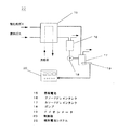
図1に、本発明に関連する発明の実施の形態1における燃料電池システム22の構成を示す。
FIG. 1 shows a configuration of a
実施の形態1の燃料電池システム22は、燃料電池15、アノードドレインタンク16、カソードドレインタンク17、ポンプ18、Fイオンメータ19、及び制御部20を備えている。
The
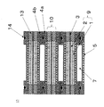
また、図2に、本発明に関連する発明の実施の形態1における高分子電解質型燃料電池15の構成を示す概略断面図を示す。なお、図2については後述する。アノードドレインタンク16は、燃料電池15のアノードから排出されるアノード排ガス(液体の排出物質及び気体の排出物質をともに含む)に含まれる排出物質から水及び水蒸気を溶出させるタンクである。カソードドレインタンク17は、燃料電池15のカソードから排出されるカソード排ガス(液体の排出物質及び気体の排出物質とをともに含む)に含まれる排出物質から水及び水蒸気を溶出させるタンクである。ポンプ18は、アノードドレインタンク16に蓄えられているドレイン水をカソードドレインタンク17に供給する手段である。Fイオンメータ19は、カソードドレインタンク17のドレイン水のFイオン量を検出する手段である。制御部20は、燃料電池15の運転を制御するとともに、燃料電池15の寿命を予測する手段である。なお、制御部20のうち燃料電池15の寿命を予測する手段については、燃料電池システム22内に固定されていてもよいし、燃料電池システム22内に脱着可能に設けられていてもよい。
FIG. 2 is a schematic cross-sectional view showing the configuration of the polymer
次に、図2を参照して燃料電池15について説明する。図2に示すように、燃料電池15は、ガス拡散層1、触媒反応層2、高分子電解質膜3、セパレータ板4、ガス流路5、冷却水流路7、電極9、MEA10、ガスシール材13、及びOリング14等から構成されている。
Next, the
すなわち、水素イオンを選択的に輸送する高分子電解質膜3の両面には、白金系の金属触媒を担持したカーボン粉末を主成分とする触媒反応層2が密着して配置されている。さらに触媒反応層2の外面に、ガス通気性と導電性を兼ね備えた一対のガス拡散層1が密着して配置されている。このガス拡散層1と触媒反応層2により電極9が構成されている。
That is, the
この電極9の一方は、燃料ガスが供給される電極であって、アノードと呼ばれている。また、電極9の他方は、酸化剤ガスが供給される電極であって、カソードと呼ばれている。
One of the
なお、本発明のアノード及びカソードは、本実施の形態における触媒反応層2の外面に、ガス拡散層1を密着配置したものに限らない。本発明のアノード及びカソードは、何れもガス拡散性を有するガス拡散電極を示すものでありさえすればよい。より具体的には、アノード及びカソードは何れもガス拡散性を有する触媒層からなるものであってもよく、ガス拡散層1上に上記の触媒反応層2を形成した積層体であってもよい。更に、アノード及びカソードはガス拡散層と触媒反応層との間に他の層(例えば、ガス拡散性、電子伝導性及び撥水性を有する多孔体からなる層)を1以上配置した構成を有する積層体であってもよい。
The anode and cathode of the present invention are not limited to those in which the
電極9の外側には、電極9と高分子電解質膜3とで形成した電極電解質接合体(以下、MEAとする)10が機械的に固定されている。そして、隣接するMEA10同士が互いに電気的に直列に接続されている。さらに電極9に反応ガスを供給しかつ反応により発生したガスや余剰のガスを運び去るためのガス流路5が一方の面に形成された導電性セパレータ板4が配置されている。
An electrode electrolyte assembly (hereinafter referred to as MEA) 10 formed of the
ガス流路5は、セパレータ板4と別に設けることもできるが、セパレータ板4の表面に溝を設けてガス流路5とする方式が一般的である。セパレータ板4の他方の面には、電池温度を一定に保つための冷却水を循環させる冷却水流路7が設けられている。冷却水流路7に冷却水を循環させることにより、反応により発生した熱エネルギーは、温水などの形で利用することができる。
Although the
また、水素や空気が電池外にリークしたり、互いに混合したりしないように、さらには冷却水が電池外にリークしないように、電極9の周囲には高分子電解質膜3を挟んでガスシール材13やOリング14が配置されている。
Further, a gas seal is placed around the
なお、本実施の形態のFイオンメータ19は、本発明に関連する発明の計測部の例であり、本実施の形態の制御部20は本発明に関連する発明の寿命予測部の例であり、本実施の形態の制御部20は本発明に関連する発明の燃料電池運転部の例である。
The
次に、このような本実施の形態の動作を説明する。 Next, the operation of this embodiment will be described.
図1に示すように、燃料電池15には、酸化剤ガスと燃料ガスとが供給される。燃料電池システム22が運転中には、燃料電池15は、供給されてくる酸化剤ガスと燃料ガスとを反応させることにより発電する。酸化剤ガスと燃料ガスとが反応する際には、発熱するので、燃料電池15には、燃料電池15を冷却するための冷却水が循環している。
As shown in FIG. 1, the
そして、燃料電池15のアノード(図2の電極9のうち燃料ガスが供給される方の電極)からは、アノード排ガス(液体の排出物質及び気体の排出物質をともに含む)がアノードドレインタンク16に排出される。アノードドレインタンク16は、アノード排ガスに含まれる排出物質(水及び水蒸気)をアノードドレインタンク16に蓄えられているドレイン水に溶出させる。
From the anode of the fuel cell 15 (the electrode to which the fuel gas is supplied among the
また、燃料電池15のカソード(図2の電極9のち酸化剤ガスが供給される方の電極)からは、カソード排ガス(液体の排出物質及び気体の排出物質とをともに含む)がカソードドレインタンク17に排出される。カソードドレインタンク17は、燃料電池15のカソードから排出されるカソード排ガスに含まれる排出物質(水及び水蒸気)をカソードドレインタンク17に蓄えられているドレイン水に溶出させる。
Also, from the cathode of the fuel cell 15 (the one electrode of the
一方、ポンプ18は、アノードドレインタンク16に蓄えられているドレイン水をカソードドレインタンク17に供給する。従って、カソードドレインタンク17に蓄えられているドレイン水には、カソード排ガスからの排出物質とアノード排ガスからの排出物質とがともに溶出している。
On the other hand, the
カソードドレインタンク17には、カソードドレインタンク17のドレイン水に含まれるフッ化物イオン量を測定するためのFイオンメータ19が取り付けられている。Fイオンメータ19は、カソードドレインタンク17のドレイン水に含まれるフッ化物イオンの量を測定する。
An
つまり、アノードおよびカソード排ガスをそれぞれアノードドレインタンク16およびカソードドレインタンク17で採取し、アノードドレイン水をカソードドレインタンク17にポンプ18で送り、Fイオンメータ19は、カソードドレインタンク17で採取された合計のドレイン水中のフッ化物イオン量を経時的に測定する。。
That is, the anode and cathode exhaust gases are collected by the
次に、制御部20は、Fイオンメータ19が検出したフッ化物イオンの量から、燃料電池の残寿命を予測する。すなわち、制御部20は、Fイオンメータ19が測定したフッ化物イオン量と採取した時間からフッ化物イオン溶出速度を算出する。そして、フッ化物イオン溶出速度が一定であるという条件では、制御部20は、式(1)を用いて、燃料電池15の残寿命を予測する。
Next, the
L=(A×F/V)−Lt ・・・(1)
L:燃料電池残寿命(h)
F:高分子電解質膜中のF重量(g)
V:フッ化物イオン溶出速度(g/h)
A:係数
Lt:運転時間(h)
なお、式1の説明、及び燃料電池15の寿命予測の詳細については、後述する。
L = (A × F / V) −Lt (1)
L: Fuel cell remaining life (h)
F: F weight (g) in the polymer electrolyte membrane
V: Fluoride ion elution rate (g / h)
A: Coefficient Lt: Operating time (h)
The description of
制御部20は、燃料電池15の残寿命を予測すると、制御部20は、予測した残寿命を、燃料電池制御部20に取り付けられた残寿命メーターに表示する。
When the
なお、実施の形態1では、制御部20は、予測した残寿命を、燃料電池制御部20に取り付けられた残寿命メータに表示するとして説明したが、これに限らない。制御部20に警報ブザーを取り付けて制御部20が予測した残寿命が一定時間を切る場合に警報音を発して燃料電池の交換を促しても構わない。また、制御部20が予測した残寿命が一定時間を切る場合に、警報ランプを点灯させたり、燃料電池15の出力を自動的に低下させることも出来る。なお、安全性の観点からは、燃料電池システム22そのものをシャットダウンすることが好ましい。また、制御部20は、予測した残寿命が一定時間を切る場合にインターネットや電話回線等を利用して警報をメンテナンス会社に自動的に通知して、メンテナンス会社が適切なタイミングで燃料電池システム22のメンテナンスを行うことが出来るようにすることが出来る。
In the first embodiment, the
なお、実施の形態1では、Fイオンメーター19を用いてフッ化物イオン量を測定するとして説明したが、これに限らない。装置が大きく高価にはなるがFイオンメータ19の代わりに、イオンクロマトでフッ化物イオン量を計測しても構わない。
In addition, although
さらに、燃料電池コージェネシステムなどの場合には、残寿命を通信により所定のメンテナンス会社に送信して、適切なメンテナンスを行うこともできる。Fイオンメーター19を取り付けない場合には、一定時間毎にドレイン水を採取しこれを分析することにより複数点計測による推算で適切なメンテナンス時期を判定することもできる。
Further, in the case of a fuel cell cogeneration system or the like, the remaining life can be transmitted to a predetermined maintenance company by communication to perform appropriate maintenance. In the case where the
さらに、燃料電池15の残寿命が一定時間を切る場合に、燃料電池のスタック交換時期を電話回線などを用いて事前にメンテナンス会社等に連絡しておき、燃料電池装置から連絡を受けたメンテナンス会社等は、スタック交換時期になったら燃料電池15のスタックの交換を行うこともできる。
Further, when the remaining life of the
次に、式1の説明、及び燃料電池15の寿命予測の詳細については、説明する。
Next, description of
一般的に高分子形燃料電池に用いられる高分子電解質膜の構造式を化1に示す。
A structural formula of a polymer electrolyte membrane generally used in a polymer fuel cell is shown in

化1は、デュポン社製、ナフィオン膜の一般構造である。膜製造メーカーによって構造式が少し異なるが、この構造式から算出されるF(フッ素)量は膜全体の60〜70%となる。図2に示した燃料電池15を用いて、異なる運転条件(A〜D)で電池運転を行った。
図3は、本発明に関連する発明の実施の形態1における燃料電池システムの一部の構成を示す図である。すなわち、図3に、実施の形態1の燃料電池システム22のうち、燃料電池15、カソードドレインタンク17、アノードドレインタンク16、及びポンプ18の部分を示す。
FIG. 3 is a diagram showing a partial configuration of the fuel cell system according to
図3に示すようにアノードおよびカソード排ガスをそれぞれアノードドレインタンク16およびカソードドレインタンク17で採取し、アノードドレイン水をカソードドレインタンク17にポンプで送り、採取した合計のドレイン水中のフッ化物イオン量を経時的に測定する。このフッ化物イオン量と採取した時間からフッ化物イオン溶出速度を算出する。
As shown in FIG. 3, the anode and cathode exhaust gases are collected in the
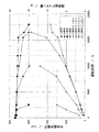
この時の燃料電池の出力電圧とフッ化物イオン溶出量との関係を図4に示す。すなわち、図4は、本発明に関連する発明の実施の形態1における燃料電池システムに用いられている燃料電池の特性の一例のグラフを示す図である。どの運転条件の場合もある時間から急激に出力電圧が低下し電池運転が不能になっている。また、運転条件の違いによりフッ化物イオン溶出速度が異なり、溶出速度の高いものは、より早い時間で出力電圧が低下している。条件Dではフッ化物イオン溶出速度が一定ではなく徐々に高くなる傾向を示している。
FIG. 4 shows the relationship between the output voltage of the fuel cell and the fluoride ion elution amount at this time. That is, FIG. 4 is a graph showing an example of the characteristics of the fuel cell used in the fuel cell system according to
図5は、図4中のフッ化物イオン溶出速度を、積算総フッ化物イオン量に置き換えた図である。すなわち、図5は、本発明に関連する発明の実施の形態1における燃料電池システムに用いられている燃料電池の特性の一例のグラフを示す図である。図5より、どの運転条件においても、出力電圧が低下する時の積算総フッ化物イオン量は、約7.5gとほぼ同じになることが分かる。図5から出力電圧が低下する時の積算総フッ化物イオン量は、高分子電解質膜中に含まれるF量の約30%であることが分かる。
FIG. 5 is a diagram in which the fluoride ion elution rate in FIG. 4 is replaced with the total amount of fluoride ions. That is, FIG. 5 is a graph showing an example of characteristics of the fuel cell used in the fuel cell system according to
以上の実験結果に基づいて、以下のように燃料電池の寿命を予測することが出来る。 Based on the above experimental results, the life of the fuel cell can be predicted as follows.
すなわち、フッ化物イオン溶出速度が一定であるA〜C条件では、燃料電池の寿命を予測する方法として上述した式(1)が導出できる。以下に式(1)を再度記載しておく。 That is, the above-described equation (1) can be derived as a method for predicting the life of the fuel cell under conditions A to C where the fluoride ion elution rate is constant. Equation (1) is described again below.
L=(A×F/V)−Lt ・・・(1)
L:燃料電池残寿命(h)
F:高分子電解質膜中のF重量(g)
V:フッ化物イオン溶出速度(g/h)
A:係数
Lt:運転時間(h)
フッ化物イオンの溶出速度が一定であるA〜C条件の場合には、出力電圧が低下する時の積算フッ化物イオン溶出量が高分子電解質膜中のF量の30%となることからAは0.3となる。この係数は、用いる高分子電解質膜の種類や厚み、大きさ、電極触媒の種類、担持量等によって変わる。この予測式を用いることにより、燃料電池の寿命予測を行うことが可能である。本実施の形態ではアノード排ガス、カソード排ガス合計のFイオン量で計算したが、アノードとカソードの排出量が一定の場合にはどちらか一方の排ガス中のFイオンを計測するだけでも可能である。
L = (A × F / V) −Lt (1)
L: Fuel cell remaining life (h)
F: F weight (g) in the polymer electrolyte membrane
V: Fluoride ion elution rate (g / h)
A: Coefficient Lt: Operating time (h)
In the case of AC conditions where the elution rate of fluoride ions is constant, the accumulated fluoride ion elution amount when the output voltage decreases is 30% of the F amount in the polymer electrolyte membrane. 0.3. This coefficient varies depending on the type, thickness and size of the polymer electrolyte membrane to be used, the type of electrode catalyst, the loading amount, and the like. By using this prediction formula, it is possible to predict the life of the fuel cell. In the present embodiment, the calculation is performed based on the total amount of F ions in the anode exhaust gas and the cathode exhaust gas. However, when the discharge amounts of the anode and the cathode are constant, it is possible to measure only the F ions in one of the exhaust gases.
D条件の場合には式(1)を用いることは出来ないが、積算総フッ化物イオン溶出量を一定時間毎に算出し、高分子電解質膜中のF量と比較検証することで燃料電池寿命を判定することが出来る。例えば、積算総フッ化物イオン量と高分子電解質膜中のフッ素量とを比較し、積算総フッ化物イオン量が高分子電解質膜中のフッ素の所定割合を超える時を燃料電池の寿命が尽きた時と判断することが出来る。 Equation (1) cannot be used in the case of the D condition, but the total total fluoride ion elution amount is calculated at regular intervals, and is compared with the F amount in the polymer electrolyte membrane to verify the fuel cell life. Can be determined. For example, the cumulative total fluoride ion amount is compared with the fluorine amount in the polymer electrolyte membrane, and the life of the fuel cell is exhausted when the cumulative total fluoride ion amount exceeds a predetermined ratio of fluorine in the polymer electrolyte membrane. It can be judged as time.
なお、燃料電池15の寿命が尽きた時とは、燃料電池15が完全に使用できなくなる時を意味するのではなく、任意に設定し得る時であり、通常、燃料電池15が完全に使用出来なくなる時より所定の時間だけ早い時に設定する。というのは、燃料電池15が寿命が尽きたと判定されてから、燃料電池15のスタックを交換するなどのメンテナンスを行う余裕を残しておく必要があるからである。
The term “when the life of the
図1の燃料電池システム22において、制御部20は、フッ化物イオンの溶出速度が一定であるという条件で式(1)を用いて燃料電池15の残寿命を予測したが、これに限らない。フッ化物イオンの溶出速度が一定でないという条件の場合には、制御部20は、フッ化物イオンの溶出速度が一定でないという条件における、積算総フッ素イオン量を利用する方法により燃料電池の寿命を予測することが出来る。
In the
すなわち、この場合には、制御部20は、積算総フッ化物イオン溶出量を一定時間毎に算出し、高分子電解質膜中のF量と比較検証することによって燃料電池の寿命を判定する。例えば、制御部20は、積算総フッ化物イオン量が高分子電解質膜中のフッ素の所定割合を超える時を燃料電池の寿命が尽きた時と判断する。
That is, in this case, the
また、式(1)では、高分子電解質膜中の総フッ素量に対して予測式を導出したが、使用する高分子膜材料が同じであれば、高分子電解質重量に変換することも可能である。この場合には、予測式は、式(1)に高分子電解質膜中のフッ素量の割合をもう一つの係数として掛け合わせた形になる。 Further, in Formula (1), a prediction formula is derived for the total fluorine amount in the polymer electrolyte membrane. However, if the polymer membrane material used is the same, it can be converted into the weight of the polymer electrolyte. is there. In this case, the prediction formula is obtained by multiplying the formula (1) by the ratio of the amount of fluorine in the polymer electrolyte membrane as another coefficient.
燃料電池の排出物質中の高分子電解質量の総積算量が、燃料電池の構成材料の高分子電解質と同じになった場合には、燃料電池として機能しなくなる。また、総積算量が同じになる前であっても高分子電解質量が減少すると、高分子電解質膜を介して原料ガスである水素や空気が互いに混じりあい電池電圧が大幅に低下して、所望の性能を発揮できなくなる。燃料電池の寿命は、燃料電池の使用形態や使用方法により、その基準が変わるため、一義的に定義することはできない設計的事項である。よって各々の燃料電池や運転条件等の数だけ、上述のような寿命予測が可能となる。また、燃料電池の寿命は、使用されている高分子電解質の種類や厚み等によって異なるので一義的に定義することは難しいが、高分子電解質膜としてフッ素系の樹脂を用いている場合、排出物質中の積算総フッ化物イオン量と高分子電解質中のフッ素量とから寿命予測することが出来る。たとえば、使用する高分子電解質膜について、予め総積算フッ化物イオン量と電池電圧との関係を調べておいて、電池電圧が初期の10%以上低下するまでの総積算フッ化物イオン量が、高分子電解質中のフッ素量の何パーセントに相当するかを寿命として、予測することが出来る。 When the total integrated amount of polymer electrolyte mass in the fuel cell discharge material becomes the same as the polymer electrolyte of the constituent material of the fuel cell, it does not function as a fuel cell. In addition, if the polymer electrolysis mass decreases even before the total integrated amount becomes the same, hydrogen and air, which are raw material gases, are mixed with each other through the polymer electrolyte membrane, and the battery voltage is greatly reduced. The performance of can not be demonstrated. The lifespan of a fuel cell is a design matter that cannot be uniquely defined because its standards vary depending on the usage and usage of the fuel cell. Therefore, the lifetime prediction as described above can be performed for each fuel cell, the number of operating conditions, and the like. In addition, the life of a fuel cell differs depending on the type and thickness of the polymer electrolyte used, so it is difficult to define it unambiguously. However, if a fluorine-based resin is used as the polymer electrolyte membrane, the emission material The lifetime can be predicted from the total amount of fluoride ions contained therein and the amount of fluorine contained in the polymer electrolyte. For example, for the polymer electrolyte membrane to be used, the relationship between the total accumulated fluoride ion amount and the battery voltage is examined in advance, and the total accumulated fluoride ion amount until the battery voltage decreases by 10% or more of the initial value is high. The percentage of the fluorine content in the molecular electrolyte can be estimated as the lifetime.
なお、上記でアノード排ガス及び/またはカソード排ガスのFイオン量を求めるとして説明したが、このアノード排ガス及び/またはカソード排ガスとは、燃料電池から排出される際に気体状態で排出される排出物質と、液体状態で排出される排出物質とをともに含むものとする。 In the above description, the amount of F ions in the anode exhaust gas and / or the cathode exhaust gas has been described. Together with the discharged substances discharged in the liquid state.
なお、本実施の形態のアノード排ガス及び/またはカソード排ガスは、本発明の排出物質の例である。また、本発明の高分子電解質膜の分解反応により生成する化学種は、本実施の形態におけるフッ化物イオンに限らない。本発明の高分子電解質膜の分解反応により生成する化学種は、高分子電解質膜の分解反応により生成する分解生成物であって、当該高分子電解質膜の構成元素を含む化学種でありさえすればよい。そして、その状態は、定量可能であれば、イオンであってもよく、ラジカルであってもよい。 The anode exhaust gas and / or the cathode exhaust gas of the present embodiment is an example of the emission material of the present invention. Further, the chemical species generated by the decomposition reaction of the polymer electrolyte membrane of the present invention is not limited to the fluoride ion in the present embodiment. The chemical species generated by the decomposition reaction of the polymer electrolyte membrane of the present invention is a decomposition product generated by the decomposition reaction of the polymer electrolyte membrane, and even a chemical species containing the constituent elements of the polymer electrolyte membrane. That's fine. The state may be an ion or a radical as long as it can be quantified.
さらに、本発明の高分子電解質膜の分解反応により生成する化学種は、本実施の形態におけるフッ化物イオンに限らず、Sを含む化学種(例えばSO4 2−)であってもよく、Cを含む化学種であってもよい。要するに本発明の高分子電解質膜の分解反応により生成する化学種は、寿命を計測可能な化学種でありさえすればよい。 Furthermore, the chemical species generated by the decomposition reaction of the polymer electrolyte membrane of the present invention is not limited to the fluoride ion in the present embodiment, but may be a chemical species containing S (for example, SO 4 2− ), and C Chemical species including In short, the chemical species generated by the decomposition reaction of the polymer electrolyte membrane of the present invention need only be a chemical species whose lifetime can be measured.
なお、本実施の形態では、燃料電池の排出物質中のフッ化物イオン量を計測するとして説明したが、これに限らない。燃料電池の高分子電解質膜がフッ素以外の材料で構成されている場合には、フッ化物イオンの代わりに燃料電池の排出物質中の高分子電解質膜を構成する高分子電解質の量あるいはそれを構成する元素の量を計測することも出来る。また、燃料電池の排出物質中のMEAを構成する高分子電解質の量を計測しても本実施の形態と同等の効果を得ることが出来る。 In the present embodiment, it has been described that the amount of fluoride ions in the exhaust material of the fuel cell is measured. However, the present invention is not limited to this. When the polymer electrolyte membrane of the fuel cell is made of a material other than fluorine, the amount of the polymer electrolyte constituting the polymer electrolyte membrane in the exhaust material of the fuel cell instead of fluoride ions It is also possible to measure the amount of elements to be performed. Further, even if the amount of the polymer electrolyte constituting the MEA in the exhausted material of the fuel cell is measured, the same effect as in the present embodiment can be obtained.
(実施の形態2)
次に、実施の形態2について説明する。
(Embodiment 2)
Next, a second embodiment will be described.
図6に、本発明の実施の形態2における燃料電池システム23の構成を示す。
FIG. 6 shows the configuration of the
実施の形態2の燃料電池システム23は、実施の形態1の燃料電池システム22のFイオンメータ19の代わりに、導電率計21を備えている。
The
導電率計21は、カソードドレインタンク17のドレイン水の電気伝導度を計測する手段である。
The
実施の形態2の燃料電池システム23は、上記以外については実施の形態1の燃料電池システム22と同様である。
The
なお、本実施の形態の導電率計21は、本発明の計測部の例であり、本実施の形態の制御部20は本発明の寿命予測部の例であり、本実施の形態の制御部20は本発明の燃料電池運転部の例である。
The
次に、このような本実施の形態の動作を実施の形態1との相違点を中心に説明する。 Next, the operation of the present embodiment will be described focusing on the differences from the first embodiment.
燃料電池15は、実施の形態1と同様にして運転される。そして、ポンプ18は、アノードドレインタンク16に蓄えられているドレイン水をカソードドレインタンク17に供給する。従って、実施の形態1と同様に、カソードドレインタンク17に蓄えられているドレイン水には、カソード排ガスからの排出物質とアノード排ガスからの排出物質とがともに溶出している。
The
カソードドレインタンク17には、アノードカソード排ガス中のドレイン水の電気伝導度を測定するための導電率計21が取り付けられている。導電率計21は、アノードカソード排ガス中のドレイン水の電気伝導度を測定する。制御部20は、電気伝導度がほぼ一定であるという条件のもとで、導電率計21により検出された電気伝導度の積算値から、式(2)を用いて燃料電池の残寿命を予測する。
A
L=(B×A×F/S)−Lt ・・・ (2)
L:燃料電池残寿命(h)
F:高分子電解質膜中のF重量(g)
S:電気伝導度(S/cm/h)
A:係数
B:補正係数
Lt:運転時間(h)
なお、式2の説明、及び燃料電池15の寿命予測の詳細については、後述する。
L = (B × A × F / S) −Lt (2)
L: Fuel cell remaining life (h)
F: F weight (g) in the polymer electrolyte membrane
S: Electric conductivity (S / cm / h)
A: Coefficient B: Correction coefficient Lt: Operating time (h)
The description of
制御部20には、予測した残寿命を表示するための残寿命メータが取り付けられており、制御部20は、この残寿命メータに、式(2)を用いて予測した燃料電池15の残寿命を表示する。
The
実施の形態2では、Fイオンメータ19の代わりに導電率計21を用いるが、導電率計21は比較的安価であるので、コスト的にも有利である。
In the second embodiment, a
なお、本実施の形態2では、制御部20は、予測した燃料電池15の残寿命を残寿命メータに表示するとして説明したが、これに限らない。制御部20に警報ブザーを取り付けて、制御部20が予測した残寿命が一定時間を切る場合に警報音を発して燃料電池の交換を促しても構わない。また、制御部20が予測した残寿命が一定時間を切る場合に、警報ランプを点灯させたり、燃料電池の出力を自動的に低下させることも出来る。なお、安全性の観点からは、燃料電池システム23そのものをシャットダウンすることが好ましい。
In the second embodiment, the
また燃料電池コージェネシステムなどの場合には、残寿命を通信により所定のメンテナンス会社に送信して、適切なメンテナンスを行うこともできる。導電率計21を取り付けない場合には、一定時間毎にドレイン水を採取しこれを分析することにより複数点計測による推算で適切なメンテナンス時期を判定することもできる。
In the case of a fuel cell cogeneration system or the like, the remaining life can be transmitted to a predetermined maintenance company by communication to perform appropriate maintenance. In the case where the
次に、式2の説明、及び燃料電池15の寿命予測の詳細については、説明する。
Next, the description of
実施の形態1と同様に、図2に示した燃料電池を用いて、異なる運転条件(A〜D)で電池運転を行った。
Similarly to
図3に、実施の形態1の燃料電池システム22のうち、燃料電池15、カソードドレインタンク17、アノードドレインタンク16、及びポンプ18の部分を示す。
FIG. 3 shows portions of the
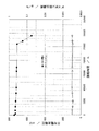
図3に示すようにカソードドレインタンク17で採取したドレイン水中の電気伝導度を経時的に測定する。このようにして測定した電気伝導度と燃料電池の出力電圧を運転時間に対して調べた結果を図7に示す。すなわち、図7は、本発明の実施の形態2における燃料電池システムに用いられている燃料電池の特性の一例のグラフを示す図である。Fイオン溶出速度に比べて、電気伝導度はややバラツキが大きくなっている。電気伝導度はドレイン水中に含まれるイオンの合算として表されるが、電気伝導度が比較的高いものについては出力電圧がより早い時間から低下し、Fイオン溶出速度の挙動に対応する結果が得られた。条件Dでは電気伝導度が経時的に高くなる傾向が見られたが、これはフッ化物イオン溶出量が高くなったためと考えられる。
As shown in FIG. 3, the electrical conductivity in the drain water collected by the
図8は、本発明の実施の形態2における燃料電池システムに用いられている燃料電池の特性の一例のグラフを示す図である。すなわち、図8に、図7中の電気伝導度を積算値として示す。図8によりどの運転条件においても、出力電圧が低下する時の電気伝導度の積算値は同じであることが分かる。出力電圧が低下する時の電気伝導度の積算値は、実施の形態1で示したように積算総フッ化物イオン量が高分子電解質膜中に含まれるF量の約30%に相当する。つまり、ドレイン水中の電気伝導度を計測することによっても燃料電池の寿命を予測することが可能である。
FIG. 8 is a graph showing an example of characteristics of the fuel cell used in the fuel cell system according to
以上のことから、電気伝導度がほぼ一定であるA〜C条件では、燃料電池の寿命を予測する方法として式(2)が導出できる。以下に式(2)を再度記載しておく。 From the above, under conditions A to C where the electric conductivity is substantially constant, equation (2) can be derived as a method for predicting the life of the fuel cell. Equation (2) is described again below.
L=(B×A×F/S)−Lt ・・・ (2)
L:燃料電池残寿命(h)
F:高分子電解質膜中のF重量(g)
S:電気伝導度(S/cm/h)
A:係数
B:補正係数
Lt:運転時間(h)
上述の場合には、Bは電気伝導度とフッ化物イオン溶出量の係数となり、この場合には20000となる。この補正係数は、先の係数Aと同様に、用いる高分子電解質膜の種類や厚み、電極触媒の種類、担持量等によって変わる。このようにして電気伝導度を測定することで燃料電池の寿命予測を行うことが可能である。本実施の形態ではアノード排ガス、カソード排ガス合計のFイオン量で計算したがアノードとカソードの排出量が一定の場合にはどちらかの排ガス中の電気伝導度を計測するだけでも可能である。
L = (B × A × F / S) −Lt (2)
L: Fuel cell remaining life (h)
F: F weight (g) in the polymer electrolyte membrane
S: Electric conductivity (S / cm / h)
A: Coefficient B: Correction coefficient Lt: Operating time (h)
In the above case, B is a coefficient of electrical conductivity and fluoride ion elution amount, in this
D条件の場合には式(2)を用いることは出来ないが、電気伝導度の積算値を一定時間毎に算出し、高分子電解質膜中のF量と補正係数Bを用いて比較検証することで燃料電池寿命を判定することが出来る。 Although the expression (2) cannot be used in the case of the D condition, the integrated value of the electrical conductivity is calculated every predetermined time, and is compared and verified using the F amount in the polymer electrolyte membrane and the correction coefficient B. Thus, the fuel cell life can be determined.
従って、図6の燃料電池システム23において、制御部20は、電気伝導度がほぼ一定であるという条件で式(2)を用いて燃料電池15の残寿命を予測したが、制御部20は、電気伝導度が一定でないという条件においても上述した方法により燃料電池の寿命を予測することが出来る。
Therefore, in the
すなわち、この場合には、制御部20は、電気伝導度の積算値を一定時間毎に算出し、高分子電解質膜中のF量と補正係数Bを用いて比較検証することによって燃料電池の寿命を判定する。例えば、制御部20で算出した電気伝導度の積算値と、高分子電解質膜中のF量とを補正係数Bを用いて比較検証、積算総フッ化物イオン量が高分子電解質膜中のフッ素の所定割合を超える時を燃料電池の寿命が尽きた時と判断する。
That is, in this case, the
このように、本実施の形態の高分子電解質型燃料電池の寿命予測法および運転方法は、携帯機器用の電源やポータブル機器用電源として高分子電解質型燃料電池を運転する場合の寿命予測法、運転方法として利用可能である。また、燃料電池自動車用あるいは家庭用燃料電池コージェネレーションシステム等を運転する場合にも適用可能であり、特に家庭用燃料電池コージェネレーション用としては有用である。 Thus, the life prediction method and operation method of the polymer electrolyte fuel cell of the present embodiment are a life prediction method when operating a polymer electrolyte fuel cell as a power source for portable devices or a power source for portable devices, It can be used as a driving method. The present invention can also be applied when operating a fuel cell automobile or household fuel cell cogeneration system, and is particularly useful for household fuel cell cogeneration.
尚、本発明に関連する発明のプログラムは、上述した本発明の燃料電池の寿命予測装置の全部又は一部の部の機能をコンピュータにより実行させるためのプログラムであって、コンピュータと協働して動作するプログラムである。 The program of the invention related to the present invention is a program for causing a computer to execute the functions of all or part of the above-described fuel cell life prediction apparatus of the present invention, and cooperates with the computer. It is a program that runs.
又、本発明に関連する発明の記録媒体は、上述した本発明の燃料電池の寿命予測装置の全部又は一部の部の全部又は一部の機能をコンピュータにより実行させるためのプログラムを記録した記録媒体であり、コンピュータにより読み取り可能且つ、読み取られた前記プログラムが前記コンピュータと協動して前記機能を実行する記録媒体である。 The recording medium of the invention related to the present invention is a recording in which a program for causing a computer to execute all or part of the functions of all or part of the above-described fuel cell life prediction apparatus of the present invention is recorded. A recording medium that is readable by a computer and that executes the function in cooperation with the computer.
尚、本発明に関連する発明の上記「一部の部」とは、それらの複数の部の内の、一つ又は幾つかの部を意味する。 Note that the “part of the above” of the invention related to the present invention means one or several of the plurality of parts.
又、本発明に関連する発明のプログラムの一利用形態は、コンピュータにより読み取り可能な記録媒体に記録され、コンピュータと協働して動作する態様であっても良い。 Further, one use form of the program of the invention related to the present invention may be an aspect in which the program is recorded on a computer-readable recording medium and operates in cooperation with the computer.
又、本発明に関連する発明のプログラムの一利用形態は、伝送媒体中を伝送し、コンピュータにより読みとられ、コンピュータと協働して動作する態様であっても良い。 Further, one use form of the program of the invention related to the present invention may be an aspect in which the program is transmitted through a transmission medium, read by a computer, and operated in cooperation with the computer.
又、記録媒体としては、ROM等が含まれ、伝送媒体としては、インターネット等の伝送媒体、光・電波・音波等が含まれる。 The recording medium includes a ROM and the like, and the transmission medium includes a transmission medium such as the Internet, light, radio waves, sound waves, and the like.
又、上述した本発明に関連する発明のコンピュータは、CPU等の純然たるハードウェアに限らず、ファームウェアや、OS、更に周辺機器を含むものであっても良い。 The computer of the invention related to the present invention described above is not limited to pure hardware such as a CPU, but may include firmware, an OS, and peripheral devices.
尚、以上説明した様に、本発明の構成は、ソフトウェア的に実現しても良いし、ハードウェア的に実現しても良い。 As described above, the configuration of the present invention may be realized by software or hardware.
本発明および本発明に関連する発明のより具体的な実施例について、以下に説明する。 More specific examples of the present invention and the invention related to the present invention will be described below.
(実施例1)
まず、図2に示すような燃料電池15を作製する。
Example 1
First, a
すなわち、高分子電解質膜3(デュポン製、ナフィオン膜、厚み50μm)にガス拡散層1を備えた触媒層付き電極9を取り付けMEA10を作製する。
That is, the
このMEA10を、その両面から気密性を有するカーボン製のセパレータ板4とシリコンゴム性のガスシール材13で挟み込んで単電池の構成とする。以上の単電池を2セル積層し電池構成単位を得て、図2に示すような構成で燃料電池の積層体を作成する。積層した単電池は全部で10セルで、両端部に金メッキを行った銅製の集電板と電気絶縁材料でできた絶縁板、さらにエンドプレートを順に配して燃料電池15を作製する。
The
作製した燃料電池の積層体に、燃料極には水素ガスを空気極に空気を流し、冷却水温度を75℃、燃料利用率を80%、空気利用率を40%、ガス加湿は水素ガスを75℃、空気を75℃の露点になるように調整して、燃料電池15を運転した。
In the produced fuel cell stack, hydrogen gas is allowed to flow to the fuel electrode, air is allowed to flow to the air electrode, the cooling water temperature is 75 ° C., the fuel usage rate is 80%, the air usage rate is 40%, The
この時、アノードおよびカソード排ガスを図3に示すような構成のドレインタンク16、17に流通させドレイン水を採取した。フッ化物イオン濃度の測定には、イオンクロマトグラフ(ICS−90、日本ダイオネクス社製)を用いた。このドレイン水中のフッ化物イオン濃度から溶出速度を算出した。この時の出力電圧とフッ化物イオン溶出速度を運転時間に対して図9に示す。すなわち、図9は、本発明に関連する発明の実施例における燃料電池システムに用いられている燃料電池の特性の一例のグラフを示す図である。これよりフッ化物イオン溶出速度は0.0003g/hとなり、約26000hで電池電圧が急激に低下することが分かる。26000hまでの積算総フッ化物イオン溶出量は約8gであり、これは、高分子電解質膜中のF割合を65%とした場合、高分子電解質中全F量の約25%に相当することが分かる。
At this time, the anode and cathode exhaust gas was circulated through the
そこで同じMEAを用いて、電池冷却水温度を95℃に上げた以外は先と同条件で運転を行った。この時のフッ化物イオン溶出速度は約0.00045g/hとなり、電池温度80℃の場合の約1.5倍になる。そこで、3000h経過時に、この燃料電池の寿命を式(1)に当てはめて残寿命の予測を行った。 Therefore, using the same MEA, operation was performed under the same conditions as above except that the battery cooling water temperature was raised to 95 ° C. The elution rate of fluoride ions at this time is about 0.00045 g / h, which is about 1.5 times that at the battery temperature of 80 ° C. Therefore, when 3000 hours passed, the remaining life was predicted by applying the life of the fuel cell to Equation (1).
L=(A×F/V)−Lt ・・・ (1)
L=(0.25×32.5/0.00045)−3000
=15056 (h)
その結果、残寿命は15056hとなる。そこで燃料電池の運転をそのまま継続した結果、図10に示すように約18000hで電池電圧の急激な低下が観測された。すなわち、図10は、本発明に関連する発明の実施例における燃料電池システムに用いられている燃料電池の特性の一例のグラフを示す図である。これより3000hでの予測寿命にほぼ一致した結果が得られる。
L = (A × F / V) −Lt (1)
L = (0.25 × 32.5 / 0.00045) −3000
= 15056 (h)
As a result, the remaining life is 15056h. Therefore, as a result of continuing the operation of the fuel cell as it was, a rapid decrease in the cell voltage was observed at about 18000 h as shown in FIG. That is, FIG. 10 is a graph showing an example of characteristics of the fuel cell used in the fuel cell system in the embodiment of the invention related to the present invention. As a result, a result almost coincident with the expected life at 3000 h can be obtained.
次に、同じMEAを用いて、運転条件を電池冷却水温度90℃、ガス加湿をアノードカソードともに50℃で、燃料極に水素ガスを空気極に酸素を流して、運転を行う。この時の出力電圧とフッ化物イオン溶出速度の関係を図11に示す。すなわち、図11は、本発明に関連する発明の実施例における燃料電池システムに用いられている燃料電池の特性の一例のグラフを示す図である。この場合にはフッ化物イオン溶出速度が経時的に大きくなることが分かる。この時、電池電圧が急激に低下する約8000hまでのフッ化物イオン量の積算値は、高分子電解質中のF量の約25%に相当しており、積算フッ化物イオン量を計測することで、燃料電池の寿命予測が可能であることが分かる。 Next, using the same MEA, the battery is operated at a battery cooling water temperature of 90 ° C., gas humidification is performed at 50 ° C. for both the anode and cathode, hydrogen gas is supplied to the fuel electrode, and oxygen is supplied to the air electrode. The relationship between the output voltage and the fluoride ion elution rate at this time is shown in FIG. That is, FIG. 11 is a graph showing an example of characteristics of the fuel cell used in the fuel cell system in the embodiment of the invention related to the present invention. In this case, it can be seen that the fluoride ion elution rate increases with time. At this time, the integrated value of the fluoride ion amount up to about 8000 h at which the battery voltage rapidly decreases corresponds to about 25% of the F amount in the polymer electrolyte. By measuring the integrated fluoride ion amount, It can be seen that the life prediction of the fuel cell is possible.
ここでは、燃料電池の電池電圧が急激に低下するまでのフッ化物イオン量をもとに寿命予測を行ったが、寿命の設定はこれに限るものではない。つまり、この半分のフッ化物イオン量が溶出した時点までを寿命として本実施例の寿命予測を行うこともできる。また、用いるMEAの厚みや種類が変わった場合には、それに応じた寿命予測を行うことができ本実施例に記載に限るものではない。 Here, the lifetime is predicted based on the amount of fluoride ions until the cell voltage of the fuel cell rapidly decreases. However, the setting of the lifetime is not limited to this. That is, the lifetime prediction of this embodiment can also be performed with the lifetime up to the point when this half fluoride ion content is eluted. In addition, when the thickness or type of MEA to be used is changed, life prediction can be performed according to the thickness or type, and the present invention is not limited to the description in this embodiment.
(実施例2)
次に、実施例1と同様のMEAを用いて図1に示す燃料電池システム22を構成して、燃料電池システム22の運転を行う。Fイオンメーター19は、Ti−5101(東興化学研究所製)を用いる。フッ化物イオン溶出量の信号が制御部20に送られ、先程の計算式から残寿命を算出し残寿命メーターに示すようにする。これにより残寿命を確認しながら燃料電池の運転を行うことが可能になる。
(Example 2)
Next, the
また同様の構成の別の燃料電池システムには、警報ランプを設置する。この場合、燃料電池寿命が残り500hで一次警報(黄色)を、250hで2次警報(赤色)を表示するように構成する。これにより事前に燃料電池の寿命を察知し、燃料電池交換等の対策を事前に行うことが出来る。 An alarm lamp is installed in another fuel cell system having the same configuration. In this case, the primary alarm (yellow) is displayed when the remaining fuel cell life is 500 h, and the secondary alarm (red) is displayed when 250 h. Thereby, the lifetime of the fuel cell can be detected in advance, and measures such as replacement of the fuel cell can be taken in advance.
また同様の構成のさらに別の燃料電池システムには、警報ブザーを設置する。この場合、燃料電池寿命が残り500hで一次警報音を、250hで2次警報音を表示するように構成する。これにより事前に燃料電池の寿命を察知し、燃料電池交換等の対策を事前に行うことが出来る。 An alarm buzzer is installed in another fuel cell system having the same configuration. In this case, the primary alarm sound is displayed when the remaining fuel cell life is 500 h, and the secondary alarm sound is displayed when 250 h. Thereby, the lifetime of the fuel cell can be detected in advance, and measures such as replacement of the fuel cell can be taken in advance.
また同様の構成の燃料電池システムには、燃料電池寿命が残り500hで電池の出力半分に、電池残寿命が250hで、自動的に燃料電池システムを停止させるように構成する。これにより事前に燃料電池の寿命を察知し、安全に燃料電池システムを停止させることが出来る。 Further, the fuel cell system having the same configuration is configured to automatically stop the fuel cell system when the remaining battery life is 500h, the output of the battery is half, and the remaining battery life is 250h. Thereby, the lifetime of the fuel cell can be detected in advance, and the fuel cell system can be stopped safely.
次に同様の構成の燃料電池コージェネシステムにおいて、Fイオンメーター19を取り付けずに運転を行う。この場合4000h毎にドレイン水を採取してフッ化物イオン量を実施例1で用いたイオンクロマトグラフで計測し、この時の溶出速度から残寿命を予測する。この結果を燃料電池運転に反映させ、予測寿命前に燃料電池を安全に停止することが出来る。この方法を用いる場合、実際にはメンテナンス会社の定期メンテナンス毎にドレイン水を採取して、燃料電池寿命を把握し、寿命時期を判断することも可能である。この場合、実際の燃料電池運転者は、燃料電池の寿命を気にすることなく、安心して燃料電池運転を継続できる。
Next, in the fuel cell cogeneration system having the same configuration, the operation is performed without attaching the
(実施例3)
次に、実施例1で採取したドレイン水の電気伝導度を、導電率計(B−173、堀場製作所製)を用いて計測する。まず運転条件が、燃料極には水素ガスを空気極に空気を流し、冷却水温度を75℃、燃料利用率を80%、空気利用率を40%、ガス加湿は水素ガスを75℃、空気を75℃の露点で運転したときのドレイン水の電気伝導度を、先に計測した電池の出力電圧と合わせて図12に示した。すなわち、図12は、本発明の実施例における燃料電池システムに用いられている燃料電池の特性の一例のグラフを示す図である。計測時間毎にやや電気伝導度がばらついているが、概ね採取した時間当たりの電気伝導度は5.5マイクロS/(cm・h)となった。電池電圧が急激に低下した26000hまでの電気伝導度の積算値は、145mS/cmであった。
(Example 3)
Next, the electrical conductivity of the drain water collected in Example 1 is measured using a conductivity meter (B-173, manufactured by Horiba, Ltd.). First operating condition, the fuel electrode flowing air to hydrogen gas to the air electrode, a cooling water temperature of 75 ° C., a fuel utilization rate of 80%, an air utilization of 40%, the gas humidification 75 ° C. The hydrogen gas, air FIG. 12 shows the electric conductivity of the drain water when operated at a dew point of 75 ° C. together with the output voltage of the battery previously measured. That is, FIG. 12 is a graph showing an example of characteristics of the fuel cell used in the fuel cell system in the embodiment of the present invention. Although the electric conductivity slightly varies at each measurement time, the electric conductivity per time generally collected was 5.5 micro S / (cm · h). The integrated value of the electrical conductivity up to 26000 h when the battery voltage rapidly decreased was 145 mS / cm.
そこで次に、電池冷却水温度を95℃に上げた時のドレイン水の電気伝導度を同様に調べる。この時の電気伝導度は約8.3マイクロS/(cm・h)となり、先の電池温度80℃の場合の1.5倍になる。そこで、3000h時点での計測値から、この燃料電池の寿命を式(2)に当てはめて残寿命の予測を行う。式(2)のBは、実施例1のフッ化物イオン溶出速度と本実施例の電気伝導度の係数から、以下のように算出する。 Therefore, the electrical conductivity of the drain water when the battery cooling water temperature is raised to 95 ° C. is examined similarly. The electrical conductivity at this time is about 8.3 micro S / (cm · h), which is 1.5 times that of the previous battery temperature of 80 ° C. Therefore, the remaining lifetime is predicted from the measured value at the time of 3000 h by applying the lifetime of the fuel cell to Equation (2). B in the formula (2) is calculated as follows from the fluoride ion elution rate of Example 1 and the coefficient of electrical conductivity of this example.
B×0.25×32.5/5.5=26000
B=17600
L=(B×A×F/S)−Lt ・・・ (2)
=(17600×0.25×32.5/8.3)−3000
= 14229 (h)
この結果、先の図10で示した電池電圧の急激な低下が観測された時間とほぼ一致する17500hであった。これより電気伝導度を用いても3000hでの予測寿命にほぼ一致した結果が得られる。
B × 0.25 × 32.5 / 5.5 = 26000
B = 17600
L = (B × A × F / S) −Lt (2)
= (17600 × 0.25 × 32.5 / 8.3) −3000
= 14229 (h)
As a result, it was 17500 h, which almost coincided with the time when the rapid decrease in the battery voltage shown in FIG. 10 was observed. As a result, even if the electric conductivity is used, a result almost coincident with the expected life at 3000 h can be obtained.
(実施例4)
次に、実施例2と同様の構成の燃料電池システムのFイオンメーターを実施例3で使用した導電率計に変えて燃料電池の運転を行った。このような燃料電池システムを図6に示す。導電率計21で測定された電気伝導度の信号は制御部20に送られる。そして、制御部20は、前述の計算式(2)から残寿命を算出し、残寿命メーターに示すようにする。これにより残寿命を確認しながら燃料電池システム23の運転を行うことが可能になる。
Example 4
Next, the fuel cell was operated by changing the F ion meter of the fuel cell system having the same configuration as in Example 2 to the conductivity meter used in Example 3. Such a fuel cell system is shown in FIG. The electrical conductivity signal measured by the
また同様の構成の別の燃料電池システムには、警報ランプを設置する。この場合、燃料電池寿命が残り500hで一次警報(黄色)を、250hで2次警報(赤色)を表示するように構成した。これにより事前に燃料電池の寿命を察知し、燃料電池交換等の対策を事前に行うことが出来る。 An alarm lamp is installed in another fuel cell system having the same configuration. In this case, the primary alarm (yellow) is displayed when the remaining fuel cell life is 500 h, and the secondary alarm (red) is displayed when 250 h. Thereby, the lifetime of the fuel cell can be detected in advance, and measures such as replacement of the fuel cell can be taken in advance.
また同様の構成のさらに別の燃料電池システムには、警報ブザーを設置する。この場合、燃料電池寿命が残り500hで一次警報音を、250hで2次警報音を表示するように構成する。これにより事前に燃料電池の寿命を察知し、燃料電池交換等の対策を事前に行うことが出来る。 An alarm buzzer is installed in another fuel cell system having the same configuration. In this case, the primary alarm sound is displayed when the remaining fuel cell life is 500 h, and the secondary alarm sound is displayed when 250 h. Thereby, the lifetime of the fuel cell can be detected in advance, and measures such as replacement of the fuel cell can be taken in advance.
また同様の構成の燃料電池システムには、燃料電池寿命が残り500hで電池の出力半分に、電池残寿命が250hで、自動的に燃料電池システムを停止させるように構成する。これにより事前に燃料電池の寿命を察知し、安全に燃料電池システムを停止させることが出来る。 Further, the fuel cell system having the same configuration is configured to automatically stop the fuel cell system when the remaining battery life is 500h, the output of the battery is half, and the remaining battery life is 250h. Thereby, the lifetime of the fuel cell can be detected in advance, and the fuel cell system can be stopped safely.
次に同様の構成の燃料電池コージェネシステムにおいて、導電率計21を取り付けずに運転を行う。この場合4000h毎にドレイン水を採取して電気伝導度を計測し、この時の溶出速度から残寿命を予測する。この結果を燃料電池運転に反映させ、予測寿命前に燃料電池を安全に停止することが出来る。この方法を用いる場合、実際にはメンテナンス会社の定期メンテナンス毎にドレイン水を採取して、燃料電池寿命を把握し、寿命時期を判断することも可能である。この場合、実際の燃料電池運転者は燃料電池の寿命を気にすることなく、安心して燃料電池運転を継続できる。
Next, in the fuel cell cogeneration system having the same configuration, the operation is performed without attaching the
本発明にかかる燃料電池の寿命予測装置、及び燃料電池システムは、燃料電池寿命予測を行うことが出来る効果を有し、また、燃料電池システムの最適運転が可能になる効果を有し、携帯機器用電源、ポータブル電源、電気自動車用電源、家庭内コージェネシステム等に使用される燃料電池、特に高分子電解質型燃料電池の燃料電池の寿命予測装置、及び燃料電池システム等として有用である。 INDUSTRIAL APPLICABILITY The fuel cell life prediction apparatus and the fuel cell system according to the present invention have the effect of being able to perform fuel cell life prediction, and have the effect of enabling the optimum operation of the fuel cell system. It is useful as a fuel cell life prediction device, a fuel cell system, and the like for use in fuel cells, portable power sources, electric vehicle power sources, domestic cogeneration systems, and the like, particularly polymer electrolyte fuel cells.
1 ガス拡散層
2 触媒反応層
3 高分子電解質膜
4 セパレータ板
5 ガス流路
7 冷却水流路
9 電極
10 MEA
12 ガス用マニホルド
13 ガスシール材
14 Oリング
15 燃料電池
16 アノードドレインタンク
17 カソードドレインタンク
18 ポンプ
19 Fイオンメータ
20 制御部
21 導電率計
DESCRIPTION OF
12
Claims (2)
発電中の前記燃料電池から排出される排出物質中に含まれる、前記高分子電解質膜の分解反応により生成する化学種の量に対応する電気伝導度を計測する計測部と、
前記計測部により計測された前記電気伝導度を利用して前記燃料電池の寿命を予測する寿命予測部とを備えた、燃料電池の寿命予測装置。 A fuel cell lifetime predicting device for predicting the lifetime of a fuel cell comprising at least a membrane electrode assembly having an anode, a cathode, and a polymer electrolyte membrane disposed between the anode and the cathode,
A measurement unit for measuring electrical conductivity corresponding to the amount of chemical species generated by a decomposition reaction of the polymer electrolyte membrane contained in an exhaust material discharged from the fuel cell during power generation;
A fuel cell life prediction apparatus comprising: a life prediction unit that predicts a life of the fuel cell using the electrical conductivity measured by the measurement unit.
前記燃料電池を運転する燃料電池運転部とを備えた、燃料電池システム。 The fuel cell life prediction apparatus according to claim 1 ,
A fuel cell system comprising: a fuel cell operating unit that operates the fuel cell.
Priority Applications (1)
| Application Number | Priority Date | Filing Date | Title |
|---|---|---|---|
| JP2004333672A JP4953219B2 (en) | 2003-11-18 | 2004-11-17 | Fuel cell life prediction apparatus and fuel cell system |
Applications Claiming Priority (3)
| Application Number | Priority Date | Filing Date | Title |
|---|---|---|---|
| JP2003388354 | 2003-11-18 | ||
| JP2003388354 | 2003-11-18 | ||
| JP2004333672A JP4953219B2 (en) | 2003-11-18 | 2004-11-17 | Fuel cell life prediction apparatus and fuel cell system |
Publications (3)
| Publication Number | Publication Date |
|---|---|
| JP2005174922A JP2005174922A (en) | 2005-06-30 |
| JP2005174922A5 JP2005174922A5 (en) | 2008-01-10 |
| JP4953219B2 true JP4953219B2 (en) | 2012-06-13 |
Family
ID=34741886
Family Applications (1)
| Application Number | Title | Priority Date | Filing Date |
|---|---|---|---|
| JP2004333672A Expired - Fee Related JP4953219B2 (en) | 2003-11-18 | 2004-11-17 | Fuel cell life prediction apparatus and fuel cell system |
Country Status (1)
| Country | Link |
|---|---|
| JP (1) | JP4953219B2 (en) |
Families Citing this family (8)
| Publication number | Priority date | Publication date | Assignee | Title |
|---|---|---|---|---|
| JP4547603B2 (en) * | 2003-12-12 | 2010-09-22 | トヨタ自動車株式会社 | Fuel cell deterioration judgment device |
| JP5111783B2 (en) * | 2006-05-15 | 2013-01-09 | 東芝燃料電池システム株式会社 | Polymer film lifetime prediction test method, test apparatus, and test program |
| JP2008140661A (en) * | 2006-12-01 | 2008-06-19 | Toyota Motor Corp | Mobile unit with fuel cell mounted |
| JP2009016270A (en) * | 2007-07-06 | 2009-01-22 | Toshiba Corp | Electronic equipment |
| US8053131B2 (en) | 2008-08-14 | 2011-11-08 | Hyundai Motor Company | Apparatus and method for determining deterioration of a fuel cell and method for preventing deterioration of the same |
| JP5145266B2 (en) * | 2009-02-24 | 2013-02-13 | 三菱重工業株式会社 | Polymer electrolyte fuel cell system and remaining life estimation method |
| JP5504932B2 (en) * | 2010-02-03 | 2014-05-28 | トヨタ自動車株式会社 | Method for predicting mechanical deterioration of solid polymer electrolyte membrane used in fuel cell, and deterioration prediction apparatus |
| CN114744257A (en) * | 2022-04-28 | 2022-07-12 | 中汽创智科技有限公司 | Diagnostic device and diagnostic method for health degree of fuel cell |
Family Cites Families (6)
| Publication number | Priority date | Publication date | Assignee | Title |
|---|---|---|---|---|
| JPS62115670A (en) * | 1985-11-15 | 1987-05-27 | Toshiba Corp | Fuel cell power generating plant |
| JPH08306377A (en) * | 1995-05-09 | 1996-11-22 | Fuji Electric Co Ltd | Carbon fluoride regeneration method for phosphoric acid type fuel cell electrode |
| JPH09259900A (en) * | 1996-03-25 | 1997-10-03 | Toshiba Corp | Phosphoric acid fuel cell |
| JPH1197049A (en) * | 1997-09-22 | 1999-04-09 | Kansai Electric Power Co Inc:The | Life predicting method for fuel cell |
| JP2003178780A (en) * | 2001-12-11 | 2003-06-27 | Matsushita Electric Ind Co Ltd | Polymer electrolyte type fuel cell system and operating method of polymer electrolyte type fuel cell |
| JP4459518B2 (en) * | 2002-09-30 | 2010-04-28 | 株式会社豊田中央研究所 | Method and system for operating polymer electrolyte fuel cell |
-
2004
- 2004-11-17 JP JP2004333672A patent/JP4953219B2/en not_active Expired - Fee Related
Also Published As
| Publication number | Publication date |
|---|---|
| JP2005174922A (en) | 2005-06-30 |
Similar Documents
| Publication | Publication Date | Title |
|---|---|---|
| JP5338903B2 (en) | Fuel cell hydrogen concentration estimation device, fuel cell system | |
| RU2402841C1 (en) | System of fuel elements | |
| US8642220B2 (en) | Method to improve fuel cell system performance using cell voltage prediction of fuel cell stack | |
| KR101755923B1 (en) | Method and system for diagnosing contamination of fuel cell stack | |
| US8956775B2 (en) | Fuel cell system and method of detecting abnormality of fuel cell system | |
| US10714771B2 (en) | Below freezing start-up method for fuel cell system | |
| JP5326423B2 (en) | FUEL CELL SYSTEM AND FUEL CELL STATE DETECTION METHOD | |
| US20130189596A1 (en) | Fuel cell system, method and program of determining cause of negative voltage, and storage medium storing program | |
| CN101957434B (en) | Method to improve reliability of a fuel cell system using low performance cell detection at low power operation | |
| US9368818B2 (en) | Humidification control method for fuel cell | |
| JP2013101914A (en) | Fuel cell and method of operating the same | |
| KR20190116630A (en) | Apparatus for controlling the operation of the fuel cell system and Method for the same | |
| US9373854B2 (en) | Solid polymer fuel cell | |
| US7422811B2 (en) | Fuel cell life predicting device and fuel cell system | |
| JP4953219B2 (en) | Fuel cell life prediction apparatus and fuel cell system | |
| CN102195052A (en) | Adaptive method for conversion of external power request to current setpoint to a fuel cell system based on stack performance | |
| JP5011670B2 (en) | Fuel cell voltage regulator | |
| JP7035982B2 (en) | Fuel cell system | |
| US10897053B2 (en) | Aging device for fuel cell stack | |
| KR101724730B1 (en) | Activity measurement method for electrode of fuel cell | |
| KR20230145803A (en) | Fuel cell cooling performance measurement test apparatus and method | |
| JP2012009182A (en) | Fuel cell system, power generation method of fuel cell and method of determining flooding | |
| KR101438957B1 (en) | Fuel cell system and control method of the same | |
| CN117895025A (en) | Activation method and device for proton exchange membrane fuel cell stack | |
| JP2005322534A (en) | Test method of polyelectrolyte type fuel cell, and polyelectrolyte type fuel cell |
Legal Events
| Date | Code | Title | Description |
|---|---|---|---|
| A621 | Written request for application examination |
Free format text: JAPANESE INTERMEDIATE CODE: A621 Effective date: 20071029 |
|
| A521 | Written amendment |
Free format text: JAPANESE INTERMEDIATE CODE: A523 Effective date: 20071119 |
|
| A977 | Report on retrieval |
Free format text: JAPANESE INTERMEDIATE CODE: A971007 Effective date: 20110322 |
|
| A131 | Notification of reasons for refusal |
Free format text: JAPANESE INTERMEDIATE CODE: A131 Effective date: 20110329 |
|
| A521 | Written amendment |
Free format text: JAPANESE INTERMEDIATE CODE: A523 Effective date: 20110516 |
|
| RD02 | Notification of acceptance of power of attorney |
Free format text: JAPANESE INTERMEDIATE CODE: A7422 Effective date: 20110516 |
|
| TRDD | Decision of grant or rejection written | ||
| A01 | Written decision to grant a patent or to grant a registration (utility model) |
Free format text: JAPANESE INTERMEDIATE CODE: A01 Effective date: 20120214 |
|
| A01 | Written decision to grant a patent or to grant a registration (utility model) |
Free format text: JAPANESE INTERMEDIATE CODE: A01 |
|
| A61 | First payment of annual fees (during grant procedure) |
Free format text: JAPANESE INTERMEDIATE CODE: A61 Effective date: 20120307 |
|
| R150 | Certificate of patent or registration of utility model |
Free format text: JAPANESE INTERMEDIATE CODE: R150 |
|
| FPAY | Renewal fee payment (event date is renewal date of database) |
Free format text: PAYMENT UNTIL: 20150323 Year of fee payment: 3 |
|
| LAPS | Cancellation because of no payment of annual fees |