US11233941B2 - Electronic device that receives line of sight input, method of controlling electronic device, and non-transitory computer readable medium - Google Patents
Electronic device that receives line of sight input, method of controlling electronic device, and non-transitory computer readable medium Download PDFInfo
- Publication number
- US11233941B2 US11233941B2 US17/078,590 US202017078590A US11233941B2 US 11233941 B2 US11233941 B2 US 11233941B2 US 202017078590 A US202017078590 A US 202017078590A US 11233941 B2 US11233941 B2 US 11233941B2
- Authority
- US
- United States
- Prior art keywords
- line
- electronic device
- sight
- control unit
- position index
- Prior art date
- Legal status (The legal status is an assumption and is not a legal conclusion. Google has not performed a legal analysis and makes no representation as to the accuracy of the status listed.)
- Active
Links
Images


Classifications
-
- H04N5/23245—
-
- H—ELECTRICITY
- H04—ELECTRIC COMMUNICATION TECHNIQUE
- H04N—PICTORIAL COMMUNICATION, e.g. TELEVISION
- H04N23/00—Cameras or camera modules comprising electronic image sensors; Control thereof
- H04N23/60—Control of cameras or camera modules
- H04N23/667—Camera operation mode switching, e.g. between still and video, sport and normal or high- and low-resolution modes
-
- G—PHYSICS
- G06—COMPUTING OR CALCULATING; COUNTING
- G06F—ELECTRIC DIGITAL DATA PROCESSING
- G06F3/00—Input arrangements for transferring data to be processed into a form capable of being handled by the computer; Output arrangements for transferring data from processing unit to output unit, e.g. interface arrangements
- G06F3/01—Input arrangements or combined input and output arrangements for interaction between user and computer
- G06F3/011—Arrangements for interaction with the human body, e.g. for user immersion in virtual reality
- G06F3/013—Eye tracking input arrangements
-
- H—ELECTRICITY
- H04—ELECTRIC COMMUNICATION TECHNIQUE
- H04N—PICTORIAL COMMUNICATION, e.g. TELEVISION
- H04N23/00—Cameras or camera modules comprising electronic image sensors; Control thereof
- H04N23/60—Control of cameras or camera modules
- H04N23/61—Control of cameras or camera modules based on recognised objects
- H04N23/611—Control of cameras or camera modules based on recognised objects where the recognised objects include parts of the human body
-
- H—ELECTRICITY
- H04—ELECTRIC COMMUNICATION TECHNIQUE
- H04N—PICTORIAL COMMUNICATION, e.g. TELEVISION
- H04N23/00—Cameras or camera modules comprising electronic image sensors; Control thereof
- H04N23/60—Control of cameras or camera modules
- H04N23/62—Control of parameters via user interfaces
-
- H—ELECTRICITY
- H04—ELECTRIC COMMUNICATION TECHNIQUE
- H04N—PICTORIAL COMMUNICATION, e.g. TELEVISION
- H04N23/00—Cameras or camera modules comprising electronic image sensors; Control thereof
- H04N23/60—Control of cameras or camera modules
- H04N23/63—Control of cameras or camera modules by using electronic viewfinders
- H04N23/631—Graphical user interfaces [GUI] specially adapted for controlling image capture or setting capture parameters
-
- H—ELECTRICITY
- H04—ELECTRIC COMMUNICATION TECHNIQUE
- H04N—PICTORIAL COMMUNICATION, e.g. TELEVISION
- H04N23/00—Cameras or camera modules comprising electronic image sensors; Control thereof
- H04N23/60—Control of cameras or camera modules
- H04N23/63—Control of cameras or camera modules by using electronic viewfinders
- H04N23/633—Control of cameras or camera modules by using electronic viewfinders for displaying additional information relating to control or operation of the camera
- H04N23/635—Region indicators; Field of view indicators
-
- H—ELECTRICITY
- H04—ELECTRIC COMMUNICATION TECHNIQUE
- H04N—PICTORIAL COMMUNICATION, e.g. TELEVISION
- H04N23/00—Cameras or camera modules comprising electronic image sensors; Control thereof
- H04N23/60—Control of cameras or camera modules
- H04N23/67—Focus control based on electronic image sensor signals
- H04N23/675—Focus control based on electronic image sensor signals comprising setting of focusing regions
-
- H—ELECTRICITY
- H04—ELECTRIC COMMUNICATION TECHNIQUE
- H04N—PICTORIAL COMMUNICATION, e.g. TELEVISION
- H04N23/00—Cameras or camera modules comprising electronic image sensors; Control thereof
- H04N23/60—Control of cameras or camera modules
- H04N23/695—Control of camera direction for changing a field of view, e.g. pan, tilt or based on tracking of objects
-
- H04N5/232127—
-
- H04N5/23218—
-
- H04N5/23299—
-
- H—ELECTRICITY
- H04—ELECTRIC COMMUNICATION TECHNIQUE
- H04N—PICTORIAL COMMUNICATION, e.g. TELEVISION
- H04N23/00—Cameras or camera modules comprising electronic image sensors; Control thereof
- H04N23/60—Control of cameras or camera modules
- H04N23/66—Remote control of cameras or camera parts, e.g. by remote control devices
- H04N23/663—Remote control of cameras or camera parts, e.g. by remote control devices for controlling interchangeable camera parts based on electronic image sensor signals
-
- H04N5/232933—
Definitions
- the present invention relates to an electronic device that receives a line of sight input, a method of controlling the electronic device, and a non-transitory computer readable medium.
- a line of sight input An electronic device which is operated by a user with his or her own line of sight (hereinafter, a line of sight input) is known.
- a line of sight input is effective when a user wants to immediately give an operation instruction to an electronic device such as a digital camera or a game machine.
- a line of sight input is largely blurred.
- a detected position of the line of sight (a viewed position) may not be directly used for an operation instruction to the electronic device.
- a means for determining a viewed position at a user's desired timing and a means for finely adjusting a final position thereof from the viewed position in accordance with the user's operation an operation more suited to the user's intention can be realized with the line of sight input.
- WO 2015/104884 describes a technique in which, when a user performs a predetermined operation, a pointer is caused to move to a viewed position, and a position of the pointer can be subsequently moved from the position of the movement destination in accordance with a direction-instructing operation.
- An aspect of the present invention is:
- an electronic device comprising:
- At least one memory and at least one processor which function as:
- a receiving unit configured to receive a line of sight input given by a line of sight of a user
- control unit configured to perform control such that
- the position index is displayed at a predetermined position on a display in response to a first operation having been performed
- the position index is displayed at a position based on the line of sight input on the display in response to the first operation having been performed.
- FIGS. 1A and 1B are external views of a digital camera according to a first embodiment.
- FIG. 2 is a configuration diagram of the digital camera according to the first embodiment.
- FIGS. 3A to 3C are diagrams showing screens for shooting settings according to the first embodiment.
- FIG. 4 is a flowchart showing shooting processing according to the first embodiment.
- FIGS. 5A to 5O are diagrams showing screens of the digital camera according to the first embodiment.
- FIG. 6 is a flowchart showing central button processing according to the first embodiment.
- an operation of returning a frame indicating a position for performing autofocus (AF) (hereinafter referred to as an AF frame) to a center of a screen that is an initial position is important, but in a case in which a line of sight input is available, there is a high possibility that a user desires to move the AF frame to a viewed position (a position pointed at by the line of sight). Therefore, since importance of the operation of returning it to the center decreases in the case in which the line of sight input is available, leaving the operation of returning the AF frame to the center as it is becomes a barrier in realizing various functions with a limited operation member of the digital camera.
- AF frame autofocus
- FIGS. 1A and 1B are external views of a digital camera 100 as an example of an apparatus to which the present invention can be applied.
- FIG. 1A is a front perspective view of the digital camera 100
- FIG. 1B is a back perspective view of the digital camera 100 .
- a display unit 28 is a display unit provided on a back surface of the camera, which displays images and various information.
- a touch panel 70 a can detect a touch operation on a display surface (an operation surface) of the display unit 28 .
- a finder outside display unit 43 is a display unit provided on an upper surface of the camera and displays various setting values of the camera such as a shutter speed and an aperture.
- a shutter button 61 is an operation unit for giving a shooting instruction.
- a mode switch 60 is an operation unit for switching between various modes.
- a terminal cover 40 is a cover that protects a connector (not shown) for connecting the digital camera 100 to a connection cable of external device.
- a main electronic dial 71 is a rotary operation member, and the user can change the setting values such as the shutter speed and the aperture by turning the main electronic dial 71 .
- a power switch 72 is an operation member for switching power of the digital camera 100 ON and OFF.
- a sub electronic dial 73 is a rotary operation member, with which movement of a selection frame, transmission of images, and the like can be performed.
- a four-way key 74 is a four-way key operation member (a cross key) having a push button of which upper, lower, left, and right portions (four directions) can be pressed. The user can perform an operation corresponding to a direction pressed in the four-way key 74 .
- a SET button 75 is a push button and is mainly used to determine a setting item or the like.
- a video button 76 is used for giving an instruction to start or stop video shooting (recording).
- An exposure state can be fixed by pressing an AE lock button 77 in a shooting standby state.
- An enlargement button 78 is an operation button for switching an enlargement mode ON and OFF in a live view display of shooting mode. By operating the main electronic dial 71 after turning on the enlargement mode, a live view image can be enlarged or reduced. In a playback mode, the enlargement button 78 functions as an enlargement button for enlarging a playback image and increasing an enlargement ratio thereof.
- a playback button 79 is an operation button for switching between the shooting mode and the playback mode.
- the mode is changed to the playback mode, and a latest image among images recorded on a recording medium 200 can be displayed on the display unit 28 .
- a menu button 81 By pressing a menu button 81 , a menu screen on which various settings can be set is displayed on the display unit 28 .
- the user can intuitively perform various settings using the menu screen displayed on the display unit 28 , the four-way key 74 , the SET button 75 , or a multi-controller (hereinafter, MC) 65 .
- MC multi-controller
- the MC 65 is capable of receiving an operation of instructing a direction among eight directions (a direction-instructing operation), up, down, left, right, up-right, up-left, down-right, and down-left, and a pressing operation of a center button while the user's thumb (one finger) is always in contact with the MC 65 . That is, the MC 65 is one operation member having the center button and an operation unit for the direction-instructing operation.
- a communication terminal 10 is a communication terminal for the digital camera 100 to communicate with a (detachable) lens unit 150 , which will be described later.
- An eyepiece unit 16 is an eyepiece unit of an eyepiece finder (a look-in type finder). The user can see a video displayed on an internal electric view finder (EVF) 29 via the eyepiece unit 16 .
- An eyepiece sensing unit 57 is an eyepiece sensing sensor that senses whether or not the user brings his or her eye into contact with the eyepiece unit 16 .
- a lid 202 is a lid of a slot for storing the recording medium 200 .
- a grip part 90 is a holding part that is shaped such that the user can easily hold it with his or her right hand when holding the digital camera 100 .
- the shutter button 61 and the main electronic dial 71 are disposed at positions at which they can be operated with the index finger of the right hand while the digital camera is held with the grip part 90 gripped by the little finger, the ring finger and the middle finger of the right hand. Further, in the same state, the sub electronic dial 73 is disposed at a position at which the sub electronic dial 73 can be operated with the thumb of the right hand.
- a thumb rest part 91 (a thumb standby position) is a grip member provided on the back surface side of the digital camera 100 at a location at which the thumb of the right hand holding the grip part 90 can be easily placed without operating any operation members.
- the thumb rest part 91 is formed of a rubber member or the like for increasing a holding force (a grip feeling).
- FIG. 2 is a block diagram showing a configuration example of the digital camera 100 according to the present embodiment.
- the lens unit 150 is a lens unit on which an interchangeable shooting lens is mounted.
- a lens 103 is normally configured of a plurality of lenses, but FIG. 2 simply shows only one lens.
- a communication terminal 6 is a communication terminal for the lens unit 150 to perform communication with the digital camera 100 .
- the lens unit 150 communicates with a system control unit 50 via the communication terminal 6 and the communication terminal 10 described above, and performs control of an aperture 1 via an aperture driving circuit 2 using an internal lens system control circuit 4 . Then, the lens system control circuit 4 performs focusing by displacing the lens 103 via an AF driving circuit 3 .
- a shutter 101 is a focal plane shutter that can freely control an exposure time of an image sensor 22 under control of the system control unit 50 .
- the image sensor 22 is an imaging element (an image sensor) configured of a charge coupled device (CCD) or a complementary metal oxide semiconductor (CMOS) element that converts an optical image into an electrical signal.
- An A/D converter 23 is used to convert an analog signal output from the image sensor 22 into a digital signal.
- An image processing unit 24 performs predetermined pixel interpolation, resize processing such as reduction, color conversion processing, and the like on data from the A/D converter 23 or from a memory control unit 15 , which will be described later. Also, the image processing unit 24 performs predetermined calculation processing using captured image data.
- the system control unit 50 performs exposure control and ranging control on the basis of the calculation results obtained by the image processing unit 24 . Thus, through the lens (TTL) type autofocus (AF) processing, automatic exposure (AE) processing, and flash pre-emission (EF) processing are performed.
- the image processing unit 24 further performs predetermined calculation processing using the captured image data and performs TTL type auto white balance (AWB) processing on the basis of the obtained calculation results.
- TTL lens
- AE automatic exposure
- EF flash pre-emission
- the memory control unit 15 controls data transmission and reception among the A/D converter 23 , the image processing unit 24 , and a memory 32 . Output data from the A/D converter 23 is directly written to the memory 32 via the image processing unit 24 and the memory control unit 15 , or via the memory control unit 15 .
- the memory 32 stores image data that is obtained by the image sensor 22 and then converted into digital data by the A/D converter 23 and image data to be displayed on the display unit 28 and the EVF 29 .
- the memory 32 has a sufficient storage capacity for storing a predetermined number of still images and a predetermined amount of time of videos and audio. Further, the memory 32 also serves as an image display memory (a video memory). The display image data written in the memory 32 is displayed on the display unit 28 or the EVF 29 via the memory control unit 15 .
- Each of the display unit 28 and the EVF 29 performs display in accordance with a signal from the memory control unit 15 on a display such as an LCD or an organic EL.
- the live view display can be performed by sequentially transferring the data that is A/D-converted by the A/D converter 23 and then stored in the memory 32 to the display unit 28 or the EVF 29 and displaying it.
- an image displayed in the live view is referred to as a live view image (LV image).
- An infrared light-emitting diode 166 is a light-emitting element for detecting a viewed position (position of a line of sight) of the user in a finder screen and irradiates an eyeball (eye) 161 of the user that has been brought into contact with the eyepiece unit 16 with infrared light.
- the infrared light emitted from the infrared light-emitting diode 166 is reflected by the eyeball (eye) 161 , and the reflected infrared light reaches a dichroic mirror 162 .
- the dichroic mirror 162 reflects only infrared light and transmits visible light.
- the infrared light of which an optical path has been changed forms an image on an imaging plane of a line of sight sensing sensor 164 via an image-forming lens 163 .
- the image-forming lens 163 is an optical member that constitutes a line of sight detection optical system.
- the line of sight sensing sensor 164 is configured of an imaging device such as a CCD image sensor.
- the line of sight sensing sensor 164 photoelectrically converts the reflected infrared light that is incident thereon into an electrical signal and outputs it to a line of sight detection circuit 165 .
- the line of sight detection circuit 165 includes at least one processor and detects a viewed position of the user from an image or movement of the eyeball (eye) 161 of the user on the basis of an output signal of the line of sight sensing sensor 164 and outputs detection information to the system control unit 50 .
- the dichroic mirror 162 , the image-forming lens 163 , the line of sight sensing sensor 164 , the infrared light-emitting diode 166 , and the line of sight detection circuit 165 constitute a line of sight detecting unit 160 (reception unit) that receives the line of sight input given by the line of sight of the user.
- the digital camera 100 uses the line of sight detecting unit 160 to detect the line of sight using a method called a corneal reflection method.
- the corneal reflection method is a method of detecting a direction and a position of the line of sight from a positional relationship between reflected light formed by the infrared light emitted from the infrared light-emitting diode 166 being reflected on the eyeball (eye) 161 (particularly the cornea) and the pupil of the eyeball (eye) 161 .
- various methods for detecting the direction and position of the line of sight such as a method called a scleral reflection method that utilizes the fact that a reflectance of light differs between the iris and the sclera.
- any other method may be used as long as it can detect the direction and position of the line of sight.
- Various setting values of the camera such as the shutter speed and the aperture are displayed on the finder outside display unit 43 via a finder outside display driving circuit 44 .
- a non-volatile memory 56 is a memory that can be electrically erased and recorded on, and uses, for example, a flash-ROM or the like.
- the non-volatile memory 56 stores constants, programs, and the like for an operation of the system control unit 50 .
- the programs referred to here are computer programs for executing various flowcharts, which will be described later in the present embodiment.
- the system control unit 50 is a control unit including at least one processor or circuit and controls the entire digital camera 100 .
- the system control unit 50 realizes each step of the processing of the present embodiment, which will be described later, by executing programs recorded in the non-volatile memory 56 described above.
- a system memory 52 for example, a RAM is used, and constants and variables for the operation of the system control unit 50 , programs read out from the non-volatile memory 56 , and the like are developed.
- the system control unit 50 performs display control by controlling the memory 32 , the display unit 28 , and the like.
- a system timer 53 is a time measuring unit that measures a time used for various controls and a time of an embedded clock.
- the mode switch 60 , a first shutter switch 62 , a second shutter switch 64 , and an operation unit 70 are operation means for inputting various operation instructions to the system control unit 50 .
- the mode switch 60 switches an operation mode of the system control unit 50 to one of a still image shooting mode, a video shooting mode, and the like. Modes included in the still image shooting mode include an auto shooting mode, an auto scene determination mode, a manual mode, an aperture priority mode (Av mode), a shutter speed priority mode (Tv mode), and a program AE mode (P mode). In addition, there are various scene modes, custom modes, and the like, which are shooting settings for each shooting scene.
- the mode switch 60 allows the user to directly switch to any of these modes.
- any of a plurality of displayed modes may be selected, and the mode may be switched thereto by using another operation member.
- the video shooting mode may include a plurality of modes.
- the first shutter switch 62 is turned on by so-called half-pressing (a shooting preparation instruction) during operation of the shutter button 61 provided on the digital camera 100 and generates a first shutter switch signal SW 1 .
- the system control unit 50 starts a shooting preparation operation such as autofocus (AF) processing, auto exposure (AE) processing, auto white balance (AWB) processing, or flash pre-emission (EF) processing in accordance with the first shutter switch signal SW 1 .
- AF autofocus
- AE auto exposure
- AVB auto white balance
- EF flash pre-emission
- the second shutter switch 64 is turned on when the operation of the shutter button 61 is completed, that is, when the shutter button 61 is fully pressed (a shooting instruction), and generates a second shutter switch signal SW 2 .
- the system control unit 50 starts a series of shooting processing operations from reading out the signal from the image sensor 22 to writing captured images as image files on the recording medium 200 .
- the operation unit 70 is various operation members serving as an input unit that receives an operation from the user.
- the operation unit 70 includes at least the following operation units (operation members). That is, the operation unit 70 includes the shutter button 61 , the multi-controller 65 , the touch panel 70 a , the main electronic dial 71 , the power switch 72 , and the sub electronic dial 73 .
- the operation unit 70 includes the four-way key 74 , the SET button 75 , the video button 76 , the AE lock button 77 , the enlargement button 78 , the playback button 79 , and the menu button 81 .
- a power control unit 80 is configured of a battery detection circuit, a DC-DC converter, a switch circuit for switching a block to be energized, and the like, and detects whether or not a battery is mounted, a type of the battery, and a remaining battery level. Further, the power control unit 80 controls the DC-DC converter on the basis of the detection results and an instruction of the system control unit 50 and supplies a necessary voltage to each unit including the recording medium 200 for a necessary period.
- a power supply unit 30 is configured of a primary battery such as an alkaline battery or a lithium battery, a secondary battery such as a NiCd battery, a NiMH battery, or a Li battery, an AC adapter, and the like.
- a recording medium interface 18 is an interface with the recording medium 200 such as a memory card or a hard disk.
- the recording medium 200 is a recording medium such as a memory card for recording captured images and is configured of a semiconductor memory, a magnetic disk, or the like.
- a communication unit 54 is connected to external device and the like in a wireless manner or by a wired cable and performs transmission and reception of a video signal and an audio signal.
- the communication unit 54 can also be connected to a wireless local area network (LAN) or the Internet. Further, the communication unit 54 can also communicate with the external device using Bluetooth (registered trademark) or Bluetooth Low Energy.
- the communication unit 54 can transmit an image (including a live view image) captured by the image sensor 22 and an image recorded in the recording medium 200 , and can receive images and various other information from the external device.
- a posture sensing unit 55 senses a posture of the digital camera 100 with respect to a direction of gravity. On the basis of the posture sensed by the posture sensing unit 55 , whether an image captured by the image sensor 22 is an image captured by holding the digital camera 100 horizontally or an image captured by holding the digital camera 100 vertically can be determined.
- the system control unit 50 can add orientation information corresponding to the posture sensed by the posture sensing unit 55 to an image file of the image captured by the image sensor 22 , or record the image by rotating it.
- an acceleration sensor, a gyro sensor, or the like can be used for the posture sensing unit 55 . Further, the system control unit 50 can also sense movement (a pan, a tilt, a lift, whether stationary or not, etc.) of the digital camera 100 using the acceleration sensor or the gyro sensor in the posture sensing unit 55 .
- the eyepiece sensing unit 57 is an eyepiece sensing sensor that senses approach (eye proximity) of an eye (object) 161 to the eyepiece unit 16 of the finder and removal (eye separation) of the eye (object).
- the system control unit 50 switches between displaying (a displayed state) and hiding (a hidden state) of the display unit 28 and the EVF 29 in accordance with a state sensed by the eyepiece sensing unit 57 .
- a state sensed by the eyepiece sensing unit 57 For example, in a case in which the digital camera 100 is in a shooting standby state and a switching setting of a display destination of the live view image is an automatic switching setting, when the eye is not in proximity, the system control unit 50 sets the display destination of the live view image to the display unit 28 and hides the EVF 29 .
- the system control unit 50 sets the display destination of the live view image to the EVF 29 and hides the display unit 28 .
- an infrared proximity sensor can be used, and it is possible to sense approach of any object to the eyepiece unit 16 of the finder incorporating the EVF 29 .
- infrared light emitted from a light projection unit (not shown) of the eyepiece sensing unit 57 is reflected by the object and received by a light receiving unit (not shown) of the infrared proximity sensor.
- eyepiece sensing unit 57 can also determine how far the object is from the eyepiece unit 16 (an eye proximity distance). As described above, the eyepiece sensing unit 57 performs eye proximity sensing of sensing an approaching distance of the object to the eyepiece unit 16 .
- the eyepiece sensing unit 57 detects that the object is in a state in which the eye is in proximity. In a case in which the object whose approach has been sensed becomes separated therefrom after the state in which the eye is in proximity (approaching state) by at least a predetermined distance, the eyepiece sensing unit 57 detects that the object is in a state in which the eye is separated therefrom.
- a threshold for detecting the eye proximity and a threshold for detecting the eye separation may be different from each other, for example, by providing hysteresis.
- the infrared proximity sensor is an example, and the eyepiece sensing unit 57 may use another sensor as long as it can sense approaching of an eye or an object for which eye proximity can be considered.
- the light projection unit and the light receiving unit of the eyepiece sensing unit 57 are assumed to be devices separate from the infrared light-emitting diode 166 and the line of sight sensing sensor 164 .
- the infrared light-emitting diode 166 may also serve as the light projection unit of the eyepiece sensing unit 57 .
- the line of sight sensing sensor 164 may also serve as the light receiving unit.
- the system control unit 50 can sense the following operations or states on the basis of an output from the line of sight detecting unit 160 .
- the term “gazing” refers to a case in which movement of a viewed position of the user does not exceed a predetermined amount within a predetermined time. That is, the system control unit 50 determines, on the basis of detection information received from the line of sight detection circuit 165 , that a region is being gazed at when a period in which the line of sight of the user is fixed in a certain region has exceeded a predetermined threshold. Therefore, it can be said that the region is a position of gaze (a region of gaze) that is a position at which gazing is performed.
- the expression “line of sight is fixed in a certain region” means that, for example, an average position of the movement of the line of sight is within the region until a predetermined period elapses and a variation (dispersion) thereof is smaller than a predetermined value.
- the touch panel 70 a and the display unit 28 can be integrally formed.
- the touch panel 70 a is configured such that a light transmittance thereof does not hinder the display on the display unit 28 and is attached to an upper layer of the display surface of the display unit 28 .
- input coordinates on the touch panel 70 a are associated with display coordinates on the display screen of the display unit 28 .
- GUI graphical user interface
- the system control unit 50 can detect the following operations or states on the touch panel 70 a.
- the touch-on is also detected at the same time. After the touch-down, the touch-on is normally continuously detected unless the touch-up is detected. When the touch-move is being detected, the touch-on is also being detected at the same time. Even when the touch-on is being detected, the touch-move is not detected unless a touch position is being moved. After touch-up of all the touching fingers or pens is detected, the touch-off is detected.
- the system control unit 50 is notified by the touch panel 70 a of these operations and states and position coordinates in which the finger or the pen is touching the touch panel 70 a via an internal bus.
- the system control unit 50 determines what operation (touch operation) has been performed on the touch panel 70 a on the basis of the information of which it is notified.
- a moving direction of the finger or the pen moving on the touch panel 70 a can also be determined for each of a vertical component and a horizontal component on the touch panel 70 a on the basis of changes in the position coordinates.
- the system control unit 50 determines that a sliding operation has been performed.
- a flick An operation of quickly moving a finger a certain distance while touching the touch panel 70 a and then releasing it is called a flick.
- the flick is an operation of quickly tracing the touch panel 70 a as if flicking it with the finger.
- a touch operation of touching a plurality of positions for example, two points
- a touch operation for moving the touch positions away from each other is referred to as a pinch-out.
- the pinch-out and pinch-in are collectively referred to as a pinch operation (or simply a pinch).
- the touch panel 70 a may be any of various types of touch panels such as a resistive film type, a capacitive type, a surface acoustic wave type, an infrared type, an electromagnetic induction type, an image recognition type, and an optical sensor type. There are a method of detecting that a touch has been performed when there is a touch on the touch panel, and a method of detecting that a touch has been performed when there is a finger or a pen approaching the touch panel, and either method may be used.
- the user can set a method of designating a position of a position index in response to the touch-move operation to either an absolute position designation or a relative position designation.
- the position index is an AF frame
- an AF position associated with the touched position is set regardless of the AF position (current AF position) that was set before the touch. That is, the position coordinates at which the touch operation is performed and the position coordinates on the display unit 28 are associated with each other.
- the position coordinates at which the touch operation is performed and the position coordinates on the display unit 28 are not associated with each other.
- the AF position is moved in a moving direction of the touch-move from the AF position (current AF position) that was set before the touch for a distance corresponding to a movement amount of the touch-move regardless of a touch-down position on the touch panel 70 a.
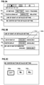
- FIG. 3A shows a setting menu screen related to shooting displayed on the EVF 29 or the display unit 28 .
- Setting items 301 to 304 are displayed on the menu screen.
- a setting item 301 indicates the AF method setting.
- the AF method setting includes “one point AF” which is for setting a position designated by the user to the AF position, and “face+tracking priority AF” which is a mode for detecting a subject (object) that is an object of shooting in a live view image, and in which the subject can be tracked and located at the AF position.
- a setting item 302 indicates the touch & drag AF setting.
- the touch & drag AF setting is a setting as to which of the above-described absolute position designation and relative position designation is used when the position index is moved using touch & drag.
- the setting item 303 indicates the line of sight function related setting. When the setting item 303 is selected, the screen changes to the screen shown in FIG. 3B .
- the setting item 304 indicates the setting related to the center button of the MC 65 . That is, the setting item 304 indicates a setting of what function is assigned to the center button. When the setting item 304 is selected, the screen changes to the screen shown in FIG. 3C .
- the EVF 29 or the display unit 28 displays setting items 305 to 307 .
- the setting item 305 indicates a setting for availability or unavailability of a line of sight function that receives the line of sight input (a line of sight AF setting).
- the setting item 306 indicates a setting of whether or not to display a pointer on the basis of the viewed position (a pointer display setting).
- the setting item 307 indicates availability or unavailability of a function (viewed position determination function) of moving (jumping) the AF frame on the basis of a detected viewed position when SW 1 is pressed.
- the line of sight function becomes available, and thus the position of the position index (AF frame) can be designated by a line of sight input.
- the line of sight function becomes unavailable, and thus the position of the position index (AF frame) cannot be designated by a line of sight input.
- the EVF 29 or the display unit 28 displays setting candidates 308 a to 308 c .
- the setting candidate 308 a is an option for setting (unavailable setting) that no special function is executed even if the center button of the MC 65 is pressed.
- the setting candidate 308 b is an option for setting on the center button a function of returning (moving) the position of the AF frame to the center on the screen.
- the setting candidate 308 c is an option for setting a function of executing AF on the center button. In the example shown in FIG. 3C , since a cursor surrounded by a thick frame indicates the setting candidate 308 a , a setting for disabling the function of the center button has been done.
- the digital camera 100 changes a position to which the AF frame is moved (displayed) when a predetermined operation is performed in a state in which the position of the AF frame that is the position index can be designated by the line of sight input and in a state in which the position of the AF frame cannot be designated by the line of sight input. This can improve operability for the user.
- the system control unit 50 Before the processing of this flowchart is started, first, when the power switch 72 is operated to switch power on, the system control unit 50 initializes flags and control variables, and then shooting a live view image in the image sensor 22 is started and the live view image is displayed on the display unit 28 . Further, on the basis of camera setting values, the system control unit 50 superimposes and displays information icons indicating the camera setting values on the live view image. Then, the processing of FIG. 4 starts. Also, the processing of the flowchart is realized by developing a program stored in the non-volatile memory 56 into the system memory 52 and executing it using the system control unit 50 .
- the system control unit 50 determines whether or not an operation of switching the line of sight function to be available or unavailable (an operation of changing the setting of the setting item 305 ) on the operation unit 70 has been performed. If the operation is performed, the process proceeds to S 402 , and if not, the process proceeds to S 403 . In S 402 , the system control unit 50 switches the line of sight function to be available or unavailable. The system control unit 50 records the setting contents of the switching results in the non-volatile memory 56 .
- the system control unit 50 determines whether or not an operation of switching a line of sight pointer display indicating a destination of the line of sight of the user to be available or unavailable (an operation of changing the setting of the setting item 306 ) on the operation unit 70 has been performed. If the operation is performed, the process proceeds to S 404 , and if not, the process proceeds to S 405 . In S 404 , the system control unit 50 switches the line of sight pointer display to be available or unavailable. The system control unit 50 records the setting contents of the switching results in the non-volatile memory 56 .
- the system control unit 50 determines whether or not an operation of switching the viewed position determination function to be available or unavailable (an operation of changing the setting of the setting item 307 ) has been performed.
- the viewed position determination function is a function of determination the viewed position in response to pressing of the first shutter switch 62 . If the operation is performed, the process proceeds to S 406 , and if not, the process proceeds to S 407 .
- the system control unit 50 switches the viewed position determination function to be available or unavailable.
- the system control unit 50 records the setting contents of the switching results in the non-volatile memory 56 .
- the system control unit 50 determines whether or not an operation of switching the touch & drag AF setting (an operation of changing the setting of the setting item 302 ) has been performed. If the operation is performed, the process proceeds to S 408 , and if not, the process proceeds to S 409 . In S 408 , the system control unit 50 switches the touch & drag AF setting. The system control unit 50 records the setting contents of the switching results in the non-volatile memory 56 .
- the system control unit 50 determines whether or not an operation of switching the AF method setting (an operation of changing the setting of the setting item 301 ) has been performed. If the operation is performed, the process proceeds to S 410 , and if not, the process proceeds to S 411 .
- the system control unit 50 switches the AF method setting. The system control unit 50 records the setting contents of the switching results in the non-volatile memory 56 .
- the system control unit 50 determines whether or not an operation of switching the function of the center button of the MC 65 (an operation of changing the setting of the setting item 304 ) has been performed. If the operation is performed, the process proceeds to S 412 , and if not, the process proceeds to S 413 .
- the system control unit 50 switches the function of the center button of the MC 65 .
- the system control unit 50 records the setting contents (information corresponding to any of the setting candidates 308 a to 308 c ) of the switching results in the non-volatile memory 56 .
- the system control unit 50 refers to the non-volatile memory 56 and determines whether or not the line of sight function is available. If the line of sight function is available, the process proceeds to S 414 , and if not, the process proceeds to S 416 .
- the system control unit 50 refers to the non-volatile memory 56 and determines whether or not the line of sight pointer display is available. If the line of sight pointer display is available, the process proceeds to S 415 , and if not, the process proceeds to S 416 .
- the system control unit 50 displays the line of sight pointer on the EVF 29 . Further, the line of sight pointer is displayed when the line of sight detecting unit 160 detects the line of sight input. Therefore, in a case in which the user is not in eye proximity to the eyepiece unit 16 and the display destination is the display unit 28 , the line of sight pointer is not displayed.
- FIG. 5C is an example of a screen in which the line of sight pointer display is performed on the EVF 29 .
- a one point AF frame 502 and a line of sight pointer 503 that is at a position based on the line of sight input are displayed to be superimposed on the live view image 501 .
- a display position of the line of sight pointer 503 moves to follow a viewed position (position of the line of sight input) detected by the line of sight detecting unit 160 .
- the reason why the user views the live view image is not limited to the case in which the user wants to designate the AF position. For this reason, although the line of sight pointer 503 moves to follow the viewed position, execution of AF at the position of the line of sight pointer 503 or update of a tracking target is not performed until an operation of determining the viewed position is performed.
- the system control unit 50 determines whether or not a direction-instructing operation has been performed on the MC 65 . If the direction-instructing operation is performed, the process proceeds to S 417 , and if not, the process proceeds to S 422 .
- the system control unit 50 refers to the non-volatile memory 56 and determines whether or not the AF method is “face+tracking priority AF”. If the AF method is “face+tracking priority AF”, the process proceeds to S 419 , and if not, the process proceeds to S 418 .
- the system control unit 50 moves the one point AF frame 502 in accordance with the direction-instructing operation on the MC 65 .
- the movement of the AF frame 502 in accordance with the direction-instructing operation on the MC 65 is a movement that does not depend on the viewed position (when the line of sight pointer 503 is displayed, its display position) while the direction-instructing operation on the MC 65 is performed even when the line of sight input is available.
- FIGS. 5A and 5B are screen examples of the EVF 29 or the display unit 28 when the system control unit 50 moves the one point AF frame 502 . From a state in which the one point AF frame 502 is displayed at a center of a screen as shown in FIG. 5A , for example, if instruction operations in a downwardly rightward direction are performed on the MC 65 several times, the one point AF frame 502 moves in the downwardly rightward direction of the screen as shown in FIG. 5B .
- the system control unit 50 determines whether or not a specific type of subject (a person's face, a person's eye, an animal, a vehicle, a building, etc.) is detected from the live view image captured by the image sensor 22 . If the specific type of subject is detected, the process proceeds to S 420 , and if not, the process proceeds to S 422 .
- the detection of the specific type of subject can be realized by the system control unit 50 interpreting (analyzing) the live view image captured by the image sensor 22 (subject recognition processing).
- the system control unit 50 determines whether or not there is one detected subject. If the number of detected subjects is one, the process proceeds to S 422 , and if not, the process proceeds to S 421 .
- FIGS. 5F and 5G are screen examples of the EVF 29 or the display unit 28 when determining (switching) the subject to be tracked.
- a face detection frame 505 and left and right icons 508 are displayed to be superimposed on the live view image 501 including subjects 504 a and 504 b .
- the face detection frame 505 and the left and right icons 508 are superimposed on the subject 504 b , and are set to track the subject 504 b .
- the left and right icons 508 indicate that the subject to be tracked (selected) can be switched by the MC 65 or the four-way key 74 . From the state of FIG.
- the system control unit 50 determines whether or not the center button of the MC 65 has been pressed. If the center button is pressed, the process proceeds to S 423 , and if not, the process proceeds to S 424 .
- the system control unit 50 executes processing (center button processing) in response to the pressing of the center button of the MC 65 . Also, the center button processing will be described later in detail with reference to the flowchart shown in FIG. 6 .
- the system control unit 50 determines whether or not a shooting operation (half-pressing and full-pressing of the shutter button 61 ) has been performed on the operation unit 70 . If the operation is performed, the process proceeds to S 425 , and if not, the process proceeds to S 426 .
- the system control unit 50 performs AF at the current position of the one point AF frame or the position of the tracking frame to perform shooting (not shooting of a live view image, but a series of processing steps until a main exposure is performed and images are recorded as image files on the recording medium 200 ). Therefore, in the present embodiment, it can be said that the tracking frame is the AF frame.
- the system control unit 50 determines whether or not another operation has been performed on the operation unit 70 . If the operation is performed, the processing proceeds to S 427 , and if not, the processing proceeds to S 428 .
- the system control unit 50 performs processing in response to the operation performed in S 426 .
- This processing includes, for example, video shooting in response to a start operation for video recording, an operation of moving an AE position, and the like.
- the system control unit 50 determines whether or not an end operation has been performed on the operation unit 70 . If the end operation is performed, the process of the flowchart ends, and if not, the process proceeds to S 401 .
- the system control unit 50 determines whether or not a function assigned to the center button of the MC 65 is a “function of returning the AF frame to the center of the screen” (the setting candidate 308 b ). If the function assigned to the center button is the “function of returning the AF frame to the center of the screen”, the process proceeds to S 603 , and if not, the process proceeds to S 602 .
- the system control unit 50 executes the function assigned to the center button of the MC 65 .
- the assigned function is “execution of AF” (the setting candidate 308 c )
- the system control unit 50 executes AF on the basis of the current AF method and the position of the AF frame (one point AF frame or tracking frame).
- the system control unit 50 determines whether or not the line of sight function is available. If the line of sight function is available, the process proceeds to S 604 , and if not, the process proceeds to S 610 .
- the system control unit 50 determines whether or not the line of sight input has been detected. If the line of sight input is detected, the process proceeds to S 605 , and if not, the process proceeds to S 610 .
- the system control unit 50 determines whether or not the AF method is “face+tracking priority AF”. If the AF method is “face+tracking priority AF”, the processing proceeds to S 607 , and if not, the processing proceeds to S 606 .
- the system control unit 50 displays (moves) the one point AF frame 502 at the position of the line of sight pointer 503 (the position at which the line of sight is detected).
- FIGS. 5C and 5D are examples of screens on the EVF 29 when the one point AF frame 502 is moved to the viewed position.
- the one point AF frame 502 and the line of sight pointer 503 are displayed to be superimposed on the live view image 501 .
- the one point AF frame 502 and the line of sight pointer 503 are displayed at positions apart from each other.
- the one point AF frame 502 moves to the position of the line of sight pointer 503 . Further, after that, when a direction-instructing operation is performed on the MC 65 , as shown in FIG. 5E , the one point AF frame 502 can be finely adjusted from the viewed position (S 416 to S 418 ).
- the movement of the AF frame 502 in response to the direction-instructing operation on the MC 65 is a movement that does not depend on the viewed position (when the line of sight pointer 503 is displayed, its display position) while the direction-instructing operation on the MC 65 is performed even when the line of sight input is available.
- the system control unit 50 determines whether or not the detected subject is being tracked. If the subject is being tracked, the process proceeds to S 609 , and if not, the process proceeds to S 608 .
- the system control unit 50 selects the subject at the viewed position and starts tracking of the subject.
- the system control unit 50 cancels tracking (a tracking state) for the subject. Here, when the tracking of the subject is canceled, the system control unit 50 hides the tracking frame.
- FIGS. 5J to 5O are examples of screens in the EVF 29 for tracking a subject using the line of sight when the AF method is “face+tracking priority AF”.
- the line of sight pointer 503 and the face detection frame 505 are displayed to be superimposed on the live view image 501 including the subject 504 .
- the line of sight pointer 503 moves in accordance with the viewed position.
- the system control unit 50 may hide the line of sight pointer 503 as shown in FIG. 5K and change the face detection frame 505 to a face detection frame 507 expressing adsorption. Further, in this case, the system control unit 50 may simply hide the line of sight pointer 503 and display the face detection frame 505 .
- the system control unit 50 displays the tracking frame 506 on the subject at the position of the line of sight pointer 503 as shown in FIG. 5L and starts tracking of the subject. Also, in this case, if the subject does not present at the position of the line of sight pointer 503 , the system control unit 50 does not display the tracking frame 506 and does not track the subject, but the one point AF frame 502 may be displayed at the position of the line of sight pointer 503 .
- the system control unit 50 may simply hide the line of sight pointer 503 and display the tracking frame 506 .
- the system control unit 50 displays the tracking frame 506 for the subject of the house as shown in FIG. 5O and starts tracking of the subject of the house.
- the display state of FIG. 5O is changed to the display state of FIG. 5J , FIG. 5K , or FIG. 5N (in a case in which the line of sight pointer is displayed).
- the display state of FIG. 5I is changed to the display state of FIG. 5H (in a case in which the line of sight pointer is not displayed).
- the system control unit 50 determines whether or not the AF method is “face+tracking priority AF”. If the AF method is “face+tracking priority AF”, the process proceeds to S 612 , and if not, the process proceeds to S 611 .
- the system control unit 50 displays (moves) the one point AF frame 502 at the center of the screen (in the middle of the screen) of the EVF 29 or the display unit 28 .
- the center button of the MC 65 is pressed in the display state as shown in FIG. 5B
- the display is updated in response thereto as shown in FIG. 5A
- the one point AF frame 502 moves to the center of the screen.
- the AF position can be reset to the center faster than performing the direction-instructing operation on the MC 65 .
- the reset to the center of the screen is movement to a position (center) that does not depend on the viewed position (line of sight input position).
- the system control unit 50 determines whether or not the detected subject is being tracked. If the tracking is in progress, the process proceeds to S 614 , and if not, the process proceeds to S 613 .
- the system control unit 50 selects a subject in the center of the screen of the EVF 29 or the display unit 28 and starts tracking of the subject.
- the system control unit 50 cancels tracking (tracking state) of the subject.
- FIGS. 5H and 5I are examples of screens for tracking a subject when the line of sight is not used.
- the live view image 501 is displayed and the subject is not being tracked.
- the system control unit 50 displays the tracking frame 506 on the subject at the center of the screen as shown in FIG. 5I and starts tracking of the subject. Also, if there is no trackable subject in the center of the screen when the center button of the MC 65 is pressed, the tracking frame 506 is not displayed and the subject is not tracked.
- the determination processing at the viewed position is performed instead of the processing of returning the AF frame to the center, thereby realizing improvement of operability.
- the MC 65 since the MC 65 has the means for jumping to the viewed position and the means for fine adjustment, the two means are disposed at positions physically close to each other, and thus quick operation can be realized.
- the present invention is not limited thereto.
- it may be an operation member capable of switching between a direction-instruction operation and an operation unrelated to a direction.
- a combination of a touch-move operation (a directional instruction) and a tap operation (an instruction having no relation to a direction) on the touch panel may be used, and a combination of a touch-move operation (a directional instruction) and a strong press (an instruction having no relation to a direction) on a pressure-sensitive touch panel may be used.
- a combination of a pair of a direction-instructing operation member and a button located at a position surrounded by them such as the four-way key 74 and the SET button 75 may be used.
- the four-way key 74 and the SET button 75 can be regarded as one operation member.
- the pair of direction-instructing operations may be performed not only by the four-way key 74 but also by a rotary operation member.
- the MC 65 is disposed at the position at which it is easily touched while holding the camera so that it can be easily operated at the time of shooting, but on the other hand, in the case of carrying the camera around, there is a concern of erroneous operation such as touching the camera unintentionally and changing the position of the AF frame. For this reason, in a default setting, a setting in which processing in response to an operation on the MC 65 is disabled during the shooting mode processing. However, if the line of sight function is available even in the disabled state, processing in response to an operation on the eight directions or on the center button of the MC 65 may be set to be available.
- system control unit 50 may be set such that the AF frame can be moved in response to the pressing of the center button if the line of sight function is available even though the movement of the AF frame in response to the pressing of the center button is unavailable if the line of sight function is unavailable.
- system control unit 50 may be performed by one piece of hardware, and a plurality of pieces of hardware (for example, a plurality of processors and circuits) may share the processing to control the entire apparatus.
- the present invention is not limited to this example and is applicable to any electronic device that can be operated by the line of sight input. That is, the present invention is applicable to a personal computer, a PDA, a mobile phone terminal, a portable image viewer, a print apparatus including a display, a digital photo frame, a music player, a game machine, an electronic book reader, and the like.
- the present invention is not limited to an imaging apparatus main body such as a digital camera, and may be also applicable to a control apparatus that communicates with an imaging apparatus (including a network camera) via a wired or wireless communication and remotely controls the imaging apparatus.
- the apparatus that remotely controls the imaging apparatus include apparatuses such as a smartphone, a tablet PC, and a desktop PC.
- the imaging apparatus can be controlled remotely by notifying the imaging apparatus of a command for performing various operations and settings from the control apparatus side on the basis of an operation performed on the control apparatus side and processing performed on the control apparatus side.
- a live view image captured by the imaging apparatus may be received via a wired or wireless communication and displayed on the control apparatus side.
- Embodiment(s) of the present invention can also be realized by a computer of a system or apparatus that reads out and executes computer executable instructions (e.g., one or more programs) recorded on a storage medium (which may also be referred to more fully as a ‘non-transitory computer-readable storage medium’) to perform the functions of one or more of the above-described embodiment(s) and/or that includes one or more circuits (e.g., application specific integrated circuit (ASIC)) for performing the functions of one or more of the above-described embodiment(s), and by a method performed by the computer of the system or apparatus by, for example, reading out and executing the computer executable instructions from the storage medium to perform the functions of one or more of the above-described embodiment(s) and/or controlling the one or more circuits to perform the functions of one or more of the above-described embodiment(s).
- computer executable instructions e.g., one or more programs
- a storage medium which may also be referred to more fully as a
- the computer may comprise one or more processors (e.g., central processing unit (CPU), micro processing unit (MPU)) and may include a network of separate computers or separate processors to read out and execute the computer executable instructions.
- the computer executable instructions may be provided to the computer, for example, from a network or the storage medium.
- the storage medium may include, for example, one or more of a hard disk, a random-access memory (RAM), a read only memory (ROM), a storage of distributed computing systems, an optical disk (such as a compact disc (CD), digital versatile disc (DVD), or Blu-ray Disc (BD)TM), a flash memory device, a memory card, and the like.
Landscapes
- Engineering & Computer Science (AREA)
- Multimedia (AREA)
- Signal Processing (AREA)
- General Engineering & Computer Science (AREA)
- Theoretical Computer Science (AREA)
- Human Computer Interaction (AREA)
- Physics & Mathematics (AREA)
- General Physics & Mathematics (AREA)
- Studio Devices (AREA)
- Indication In Cameras, And Counting Of Exposures (AREA)
- Position Input By Displaying (AREA)
- Automatic Focus Adjustment (AREA)
- Exposure Control For Cameras (AREA)
- Focusing (AREA)
- Viewfinders (AREA)
- Camera Bodies And Camera Details Or Accessories (AREA)
- User Interface Of Digital Computer (AREA)
Applications Claiming Priority (3)
| Application Number | Priority Date | Filing Date | Title |
|---|---|---|---|
| JP2019193317A JP7467071B2 (ja) | 2019-10-24 | 2019-10-24 | 電子機器、電子機器の制御方法、プログラム、記憶媒体 |
| JP2019-193317 | 2019-10-24 | ||
| JPJP2019-193317 | 2019-10-24 |
Publications (2)
| Publication Number | Publication Date |
|---|---|
| US20210127063A1 US20210127063A1 (en) | 2021-04-29 |
| US11233941B2 true US11233941B2 (en) | 2022-01-25 |
Family
ID=75586487
Family Applications (1)
| Application Number | Title | Priority Date | Filing Date |
|---|---|---|---|
| US17/078,590 Active US11233941B2 (en) | 2019-10-24 | 2020-10-23 | Electronic device that receives line of sight input, method of controlling electronic device, and non-transitory computer readable medium |
Country Status (2)
| Country | Link |
|---|---|
| US (1) | US11233941B2 (enExample) |
| JP (1) | JP7467071B2 (enExample) |
Cited By (1)
| Publication number | Priority date | Publication date | Assignee | Title |
|---|---|---|---|---|
| US11470239B2 (en) * | 2019-07-31 | 2022-10-11 | Canon Kabushiki Kaisha | Electronic device for receiving line of sight input, method of controlling electronic device, and non-transitory computer readable medium |
Families Citing this family (8)
| Publication number | Priority date | Publication date | Assignee | Title |
|---|---|---|---|---|
| JP7451162B2 (ja) * | 2019-12-13 | 2024-03-18 | キヤノン株式会社 | 撮像装置 |
| JP7606393B2 (ja) * | 2021-04-14 | 2024-12-25 | 株式会社三共 | 遊技機 |
| JP7606394B2 (ja) * | 2021-04-14 | 2024-12-25 | 株式会社三共 | 遊技機 |
| JP7716219B2 (ja) * | 2021-04-14 | 2025-07-31 | 株式会社三共 | 遊技機 |
| JP7611061B2 (ja) * | 2021-04-14 | 2025-01-09 | 株式会社三共 | 遊技機 |
| JP7739037B2 (ja) * | 2021-04-30 | 2025-09-16 | キヤノン株式会社 | 撮像装置及びその制御方法、並びにプログラム |
| JP7770822B2 (ja) * | 2021-09-06 | 2025-11-17 | キヤノン株式会社 | 電子機器及び制御方法 |
| JP2023077991A (ja) * | 2021-11-25 | 2023-06-06 | キヤノン株式会社 | 撮像装置及びその制御方法 |
Citations (13)
| Publication number | Priority date | Publication date | Assignee | Title |
|---|---|---|---|---|
| US20070018069A1 (en) * | 2005-07-06 | 2007-01-25 | Sony Corporation | Image pickup apparatus, control method, and program |
| US20120013786A1 (en) * | 2010-07-16 | 2012-01-19 | Canon Kabushiki Kaisha | Focus adjustment apparatus and method, and image capturing apparatus and control method thereof |
| US20130222301A1 (en) * | 2012-02-24 | 2013-08-29 | Samsung Electronics Co., Ltd. | Method and apparatus for moving contents in terminal |
| US20150022682A1 (en) * | 2013-07-22 | 2015-01-22 | Canon Kabushiki Kaisha | Optical device capable of selecting focus detection point, method of controlling the same, and storage medium |
| WO2015104884A1 (ja) | 2014-01-08 | 2015-07-16 | ソニー株式会社 | 情報処理システム、情報処理方法およびプログラム |
| US20170366743A1 (en) * | 2014-01-15 | 2017-12-21 | Samsung Electronics Co., Ltd. | Method for setting image capture conditions and electronic device performing the same |
| US20180220062A1 (en) * | 2017-01-30 | 2018-08-02 | Canon Kabushiki Kaisha | Image capture apparatus and control method for the same |
| US20180224723A1 (en) * | 2017-02-06 | 2018-08-09 | Canon Kabushiki Kaisha | Electronic apparatus, method for controlling the same, and storage medium |
| US20180234631A1 (en) * | 2017-02-14 | 2018-08-16 | Canon Kabushiki Kaisha | Imaging apparatus, method for controlling the same, and storage medium |
| US20180324351A1 (en) * | 2015-11-17 | 2018-11-08 | Sony Corporation | Control device, control method, and program |
| US20190020826A1 (en) * | 2017-07-13 | 2019-01-17 | Canon Kabushiki Kaisha | Control apparatus, image capturing apparatus, and non-transitory computer-readable storage medium |
| US20190146584A1 (en) * | 2017-11-15 | 2019-05-16 | Sony Interactive Entertainment Inc. | Line-of-sight detection apparatus |
| US10459190B2 (en) * | 2017-06-05 | 2019-10-29 | Olympus Corporation | Imaging apparatus, imaging method, and computer-readable recording medium |
Family Cites Families (7)
| Publication number | Priority date | Publication date | Assignee | Title |
|---|---|---|---|---|
| JPH05288982A (ja) * | 1992-04-09 | 1993-11-05 | Olympus Optical Co Ltd | 注視点選択装置 |
| JPH05333259A (ja) * | 1992-06-02 | 1993-12-17 | Canon Inc | 視線検出手段を有した光学装置 |
| JPH07283994A (ja) * | 1994-04-12 | 1995-10-27 | Canon Inc | 撮像装置 |
| JP2007133027A (ja) * | 2005-11-08 | 2007-05-31 | Canon Inc | 撮像装置 |
| JP2015028733A (ja) * | 2013-07-30 | 2015-02-12 | コニカミノルタ株式会社 | 操作装置および画像処理装置 |
| JP6260255B2 (ja) * | 2013-12-18 | 2018-01-17 | 株式会社デンソー | 表示制御装置およびプログラム |
| JP6991033B2 (ja) * | 2017-10-17 | 2022-01-12 | キヤノン株式会社 | 電子機器及びその制御方法 |
-
2019
- 2019-10-24 JP JP2019193317A patent/JP7467071B2/ja active Active
-
2020
- 2020-10-23 US US17/078,590 patent/US11233941B2/en active Active
Patent Citations (16)
| Publication number | Priority date | Publication date | Assignee | Title |
|---|---|---|---|---|
| US20070018069A1 (en) * | 2005-07-06 | 2007-01-25 | Sony Corporation | Image pickup apparatus, control method, and program |
| US20120013786A1 (en) * | 2010-07-16 | 2012-01-19 | Canon Kabushiki Kaisha | Focus adjustment apparatus and method, and image capturing apparatus and control method thereof |
| US20130222301A1 (en) * | 2012-02-24 | 2013-08-29 | Samsung Electronics Co., Ltd. | Method and apparatus for moving contents in terminal |
| US20150022682A1 (en) * | 2013-07-22 | 2015-01-22 | Canon Kabushiki Kaisha | Optical device capable of selecting focus detection point, method of controlling the same, and storage medium |
| US9445005B2 (en) * | 2013-07-22 | 2016-09-13 | Canon Kabushiki Kaisha | Optical device capable of selecting focus detection point, method of controlling the same, and storage medium |
| WO2015104884A1 (ja) | 2014-01-08 | 2015-07-16 | ソニー株式会社 | 情報処理システム、情報処理方法およびプログラム |
| US20170366743A1 (en) * | 2014-01-15 | 2017-12-21 | Samsung Electronics Co., Ltd. | Method for setting image capture conditions and electronic device performing the same |
| US20180324351A1 (en) * | 2015-11-17 | 2018-11-08 | Sony Corporation | Control device, control method, and program |
| US20180220062A1 (en) * | 2017-01-30 | 2018-08-02 | Canon Kabushiki Kaisha | Image capture apparatus and control method for the same |
| US20180224723A1 (en) * | 2017-02-06 | 2018-08-09 | Canon Kabushiki Kaisha | Electronic apparatus, method for controlling the same, and storage medium |
| US10527911B2 (en) * | 2017-02-06 | 2020-01-07 | Canon Kabushiki Kaisha | Electronic apparatus configured to select positions on a display unit by touch operation and control method thereof |
| US20180234631A1 (en) * | 2017-02-14 | 2018-08-16 | Canon Kabushiki Kaisha | Imaging apparatus, method for controlling the same, and storage medium |
| US10459190B2 (en) * | 2017-06-05 | 2019-10-29 | Olympus Corporation | Imaging apparatus, imaging method, and computer-readable recording medium |
| US20190020826A1 (en) * | 2017-07-13 | 2019-01-17 | Canon Kabushiki Kaisha | Control apparatus, image capturing apparatus, and non-transitory computer-readable storage medium |
| US10863079B2 (en) * | 2017-07-13 | 2020-12-08 | Canon Kabushiki Kaisha | Control apparatus, image capturing apparatus, and non-transitory computer-readable storage medium |
| US20190146584A1 (en) * | 2017-11-15 | 2019-05-16 | Sony Interactive Entertainment Inc. | Line-of-sight detection apparatus |
Cited By (1)
| Publication number | Priority date | Publication date | Assignee | Title |
|---|---|---|---|---|
| US11470239B2 (en) * | 2019-07-31 | 2022-10-11 | Canon Kabushiki Kaisha | Electronic device for receiving line of sight input, method of controlling electronic device, and non-transitory computer readable medium |
Also Published As
| Publication number | Publication date |
|---|---|
| JP2021068208A (ja) | 2021-04-30 |
| JP7467071B2 (ja) | 2024-04-15 |
| US20210127063A1 (en) | 2021-04-29 |
Similar Documents
| Publication | Publication Date | Title |
|---|---|---|
| US11233941B2 (en) | Electronic device that receives line of sight input, method of controlling electronic device, and non-transitory computer readable medium | |
| US11500458B2 (en) | Electronic apparatus, method for controlling the electronic apparatus, and storage medium | |
| US11175737B2 (en) | Electronic device for receiving line of sight input, method of controlling electronic device, and non-transitory computer readable medium | |
| CN112104809B (zh) | 电子装置、电子装置的控制方法及存储介质 | |
| US12120415B2 (en) | Electronic device, control method thereof, and recording medium | |
| US12457421B2 (en) | Electronic device, control method, and non-transitory computer readable medium | |
| US11240419B2 (en) | Electronic device that can execute function in accordance with line of sight of user, method of controlling electronic device, and non-transitory computer readable medium | |
| US20210037189A1 (en) | Electronic device for receiving line of sight input, method of controlling electronic device, and non-transitory computer readable medium | |
| US11843849B2 (en) | Electronic device, control method thereof, and recording medium | |
| US11442244B2 (en) | Imaging device | |
| JP2021145191A (ja) | 撮像装置およびその制御方法、プログラム、並びに記憶媒体 | |
| US11435648B2 (en) | Image capture apparatus and control method | |
| US11526264B2 (en) | Electronic apparatus for enlarging or reducing display object, method of controlling electronic apparatus, and non-transitory computer readable medium | |
| US20230018866A1 (en) | Electronic device that displays a plurality of display items on a display and method for controlling electronic device | |
| US11526208B2 (en) | Electronic device and method for controlling electronic device | |
| JP2021018634A (ja) | 電子機器およびその制御方法 | |
| US11538191B2 (en) | Electronic apparatus using calibration of a line of sight input, control method of electronic apparatus using calibration of a line of sight input, and non-transitory computer readable medium thereof | |
| JP7451255B2 (ja) | 電子機器及びその制御方法 | |
| JP2022095306A (ja) | 表示制御装置及びその制御方法 |
Legal Events
| Date | Code | Title | Description |
|---|---|---|---|
| FEPP | Fee payment procedure |
Free format text: ENTITY STATUS SET TO UNDISCOUNTED (ORIGINAL EVENT CODE: BIG.); ENTITY STATUS OF PATENT OWNER: LARGE ENTITY |
|
| AS | Assignment |
Owner name: CANON KABUSHIKI KAISHA, JAPAN Free format text: ASSIGNMENT OF ASSIGNORS INTEREST;ASSIGNOR:OGAWA, SEIJI;REEL/FRAME:055188/0919 Effective date: 20201228 |
|
| STPP | Information on status: patent application and granting procedure in general |
Free format text: DOCKETED NEW CASE - READY FOR EXAMINATION |
|
| STPP | Information on status: patent application and granting procedure in general |
Free format text: NOTICE OF ALLOWANCE MAILED -- APPLICATION RECEIVED IN OFFICE OF PUBLICATIONS |
|
| STPP | Information on status: patent application and granting procedure in general |
Free format text: PUBLICATIONS -- ISSUE FEE PAYMENT VERIFIED |
|
| STCF | Information on status: patent grant |
Free format text: PATENTED CASE |
|
| MAFP | Maintenance fee payment |
Free format text: PAYMENT OF MAINTENANCE FEE, 4TH YEAR, LARGE ENTITY (ORIGINAL EVENT CODE: M1551); ENTITY STATUS OF PATENT OWNER: LARGE ENTITY Year of fee payment: 4 |