US11230665B2 - Lighting system having reduced melanopic spectral content - Google Patents
Lighting system having reduced melanopic spectral content Download PDFInfo
- Publication number
- US11230665B2 US11230665B2 US16/332,319 US201716332319A US11230665B2 US 11230665 B2 US11230665 B2 US 11230665B2 US 201716332319 A US201716332319 A US 201716332319A US 11230665 B2 US11230665 B2 US 11230665B2
- Authority
- US
- United States
- Prior art keywords
- light
- emitting device
- wavelength
- emission spectrum
- light source
- Prior art date
- Legal status (The legal status is an assumption and is not a legal conclusion. Google has not performed a legal analysis and makes no representation as to the accuracy of the status listed.)
- Active, expires
Links
Images


Classifications
-
- C—CHEMISTRY; METALLURGY
- C09—DYES; PAINTS; POLISHES; NATURAL RESINS; ADHESIVES; COMPOSITIONS NOT OTHERWISE PROVIDED FOR; APPLICATIONS OF MATERIALS NOT OTHERWISE PROVIDED FOR
- C09K—MATERIALS FOR MISCELLANEOUS APPLICATIONS, NOT PROVIDED FOR ELSEWHERE
- C09K11/00—Luminescent, e.g. electroluminescent, chemiluminescent materials
- C09K11/08—Luminescent, e.g. electroluminescent, chemiluminescent materials containing inorganic luminescent materials
- C09K11/77—Luminescent, e.g. electroluminescent, chemiluminescent materials containing inorganic luminescent materials containing rare earth metals
- C09K11/7728—Luminescent, e.g. electroluminescent, chemiluminescent materials containing inorganic luminescent materials containing rare earth metals containing europium
- C09K11/7734—Aluminates
-
- H—ELECTRICITY
- H10—SEMICONDUCTOR DEVICES; ELECTRIC SOLID-STATE DEVICES NOT OTHERWISE PROVIDED FOR
- H10H—INORGANIC LIGHT-EMITTING SEMICONDUCTOR DEVICES HAVING POTENTIAL BARRIERS
- H10H20/00—Individual inorganic light-emitting semiconductor devices having potential barriers, e.g. light-emitting diodes [LED]
- H10H20/80—Constructional details
- H10H20/85—Packages
- H10H20/851—Wavelength conversion means
- H10H20/8511—Wavelength conversion means characterised by their material, e.g. binder
- H10H20/8512—Wavelength conversion materials
-
- A—HUMAN NECESSITIES
- A61—MEDICAL OR VETERINARY SCIENCE; HYGIENE
- A61M—DEVICES FOR INTRODUCING MEDIA INTO, OR ONTO, THE BODY; DEVICES FOR TRANSDUCING BODY MEDIA OR FOR TAKING MEDIA FROM THE BODY; DEVICES FOR PRODUCING OR ENDING SLEEP OR STUPOR
- A61M21/00—Other devices or methods to cause a change in the state of consciousness; Devices for producing or ending sleep by mechanical, optical, or acoustical means, e.g. for hypnosis
-
- C—CHEMISTRY; METALLURGY
- C09—DYES; PAINTS; POLISHES; NATURAL RESINS; ADHESIVES; COMPOSITIONS NOT OTHERWISE PROVIDED FOR; APPLICATIONS OF MATERIALS NOT OTHERWISE PROVIDED FOR
- C09K—MATERIALS FOR MISCELLANEOUS APPLICATIONS, NOT PROVIDED FOR ELSEWHERE
- C09K11/00—Luminescent, e.g. electroluminescent, chemiluminescent materials
- C09K11/08—Luminescent, e.g. electroluminescent, chemiluminescent materials containing inorganic luminescent materials
- C09K11/77—Luminescent, e.g. electroluminescent, chemiluminescent materials containing inorganic luminescent materials containing rare earth metals
- C09K11/7728—Luminescent, e.g. electroluminescent, chemiluminescent materials containing inorganic luminescent materials containing rare earth metals containing europium
- C09K11/77347—Silicon Nitrides or Silicon Oxynitrides
-
- C—CHEMISTRY; METALLURGY
- C09—DYES; PAINTS; POLISHES; NATURAL RESINS; ADHESIVES; COMPOSITIONS NOT OTHERWISE PROVIDED FOR; APPLICATIONS OF MATERIALS NOT OTHERWISE PROVIDED FOR
- C09K—MATERIALS FOR MISCELLANEOUS APPLICATIONS, NOT PROVIDED FOR ELSEWHERE
- C09K11/00—Luminescent, e.g. electroluminescent, chemiluminescent materials
- C09K11/08—Luminescent, e.g. electroluminescent, chemiluminescent materials containing inorganic luminescent materials
- C09K11/77—Luminescent, e.g. electroluminescent, chemiluminescent materials containing inorganic luminescent materials containing rare earth metals
- C09K11/7728—Luminescent, e.g. electroluminescent, chemiluminescent materials containing inorganic luminescent materials containing rare earth metals containing europium
- C09K11/77348—Silicon Aluminium Nitrides or Silicon Aluminium Oxynitrides
-
- F—MECHANICAL ENGINEERING; LIGHTING; HEATING; WEAPONS; BLASTING
- F21—LIGHTING
- F21K—NON-ELECTRIC LIGHT SOURCES USING LUMINESCENCE; LIGHT SOURCES USING ELECTROCHEMILUMINESCENCE; LIGHT SOURCES USING CHARGES OF COMBUSTIBLE MATERIAL; LIGHT SOURCES USING SEMICONDUCTOR DEVICES AS LIGHT-GENERATING ELEMENTS; LIGHT SOURCES NOT OTHERWISE PROVIDED FOR
- F21K9/00—Light sources using semiconductor devices as light-generating elements, e.g. using light-emitting diodes [LED] or lasers
- F21K9/60—Optical arrangements integrated in the light source, e.g. for improving the colour rendering index or the light extraction
- F21K9/64—Optical arrangements integrated in the light source, e.g. for improving the colour rendering index or the light extraction using wavelength conversion means distinct or spaced from the light-generating element, e.g. a remote phosphor layer
-
- F—MECHANICAL ENGINEERING; LIGHTING; HEATING; WEAPONS; BLASTING
- F21—LIGHTING
- F21V—FUNCTIONAL FEATURES OR DETAILS OF LIGHTING DEVICES OR SYSTEMS THEREOF; STRUCTURAL COMBINATIONS OF LIGHTING DEVICES WITH OTHER ARTICLES, NOT OTHERWISE PROVIDED FOR
- F21V23/00—Arrangement of electric circuit elements in or on lighting devices
- F21V23/003—Arrangement of electric circuit elements in or on lighting devices the elements being electronics drivers or controllers for operating the light source, e.g. for a LED array
-
- H01L27/156—
-
- H01L33/502—
-
- H01L33/505—
-
- H—ELECTRICITY
- H01—ELECTRIC ELEMENTS
- H01S—DEVICES USING THE PROCESS OF LIGHT AMPLIFICATION BY STIMULATED EMISSION OF RADIATION [LASER] TO AMPLIFY OR GENERATE LIGHT; DEVICES USING STIMULATED EMISSION OF ELECTROMAGNETIC RADIATION IN WAVE RANGES OTHER THAN OPTICAL
- H01S5/00—Semiconductor lasers
- H01S5/005—Optical components external to the laser cavity, specially adapted therefor, e.g. for homogenisation or merging of the beams or for manipulating laser pulses, e.g. pulse shaping
- H01S5/0087—Optical components external to the laser cavity, specially adapted therefor, e.g. for homogenisation or merging of the beams or for manipulating laser pulses, e.g. pulse shaping for illuminating phosphorescent or fluorescent materials, e.g. using optical arrangements specifically adapted for guiding or shaping laser beams illuminating these materials
-
- H—ELECTRICITY
- H05—ELECTRIC TECHNIQUES NOT OTHERWISE PROVIDED FOR
- H05B—ELECTRIC HEATING; ELECTRIC LIGHT SOURCES NOT OTHERWISE PROVIDED FOR; CIRCUIT ARRANGEMENTS FOR ELECTRIC LIGHT SOURCES, IN GENERAL
- H05B45/00—Circuit arrangements for operating light-emitting diodes [LED]
- H05B45/20—Controlling the colour of the light
-
- H—ELECTRICITY
- H10—SEMICONDUCTOR DEVICES; ELECTRIC SOLID-STATE DEVICES NOT OTHERWISE PROVIDED FOR
- H10H—INORGANIC LIGHT-EMITTING SEMICONDUCTOR DEVICES HAVING POTENTIAL BARRIERS
- H10H20/00—Individual inorganic light-emitting semiconductor devices having potential barriers, e.g. light-emitting diodes [LED]
- H10H20/80—Constructional details
- H10H20/85—Packages
- H10H20/851—Wavelength conversion means
- H10H20/8514—Wavelength conversion means characterised by their shape, e.g. plate or foil
-
- H—ELECTRICITY
- H10—SEMICONDUCTOR DEVICES; ELECTRIC SOLID-STATE DEVICES NOT OTHERWISE PROVIDED FOR
- H10H—INORGANIC LIGHT-EMITTING SEMICONDUCTOR DEVICES HAVING POTENTIAL BARRIERS
- H10H29/00—Integrated devices, or assemblies of multiple devices, comprising at least one light-emitting semiconductor element covered by group H10H20/00
- H10H29/10—Integrated devices comprising at least one light-emitting semiconductor component covered by group H10H20/00
- H10H29/14—Integrated devices comprising at least one light-emitting semiconductor component covered by group H10H20/00 comprising multiple light-emitting semiconductor components
- H10H29/142—Two-dimensional arrangements, e.g. asymmetric LED layout
-
- A—HUMAN NECESSITIES
- A61—MEDICAL OR VETERINARY SCIENCE; HYGIENE
- A61M—DEVICES FOR INTRODUCING MEDIA INTO, OR ONTO, THE BODY; DEVICES FOR TRANSDUCING BODY MEDIA OR FOR TAKING MEDIA FROM THE BODY; DEVICES FOR PRODUCING OR ENDING SLEEP OR STUPOR
- A61M21/00—Other devices or methods to cause a change in the state of consciousness; Devices for producing or ending sleep by mechanical, optical, or acoustical means, e.g. for hypnosis
- A61M2021/0005—Other devices or methods to cause a change in the state of consciousness; Devices for producing or ending sleep by mechanical, optical, or acoustical means, e.g. for hypnosis by the use of a particular sense, or stimulus
- A61M2021/0044—Other devices or methods to cause a change in the state of consciousness; Devices for producing or ending sleep by mechanical, optical, or acoustical means, e.g. for hypnosis by the use of a particular sense, or stimulus by the sight sense
-
- F—MECHANICAL ENGINEERING; LIGHTING; HEATING; WEAPONS; BLASTING
- F21—LIGHTING
- F21Y—INDEXING SCHEME ASSOCIATED WITH SUBCLASSES F21K, F21L, F21S and F21V, RELATING TO THE FORM OR THE KIND OF THE LIGHT SOURCES OR OF THE COLOUR OF THE LIGHT EMITTED
- F21Y2115/00—Light-generating elements of semiconductor light sources
- F21Y2115/10—Light-emitting diodes [LED]
-
- Y—GENERAL TAGGING OF NEW TECHNOLOGICAL DEVELOPMENTS; GENERAL TAGGING OF CROSS-SECTIONAL TECHNOLOGIES SPANNING OVER SEVERAL SECTIONS OF THE IPC; TECHNICAL SUBJECTS COVERED BY FORMER USPC CROSS-REFERENCE ART COLLECTIONS [XRACs] AND DIGESTS
- Y02—TECHNOLOGIES OR APPLICATIONS FOR MITIGATION OR ADAPTATION AGAINST CLIMATE CHANGE
- Y02B—CLIMATE CHANGE MITIGATION TECHNOLOGIES RELATED TO BUILDINGS, e.g. HOUSING, HOUSE APPLIANCES OR RELATED END-USER APPLICATIONS
- Y02B20/00—Energy efficient lighting technologies, e.g. halogen lamps or gas discharge lamps
Definitions
- the disclosures herein generally relate to a light-emitting device with an improved non-visual response.
- a light-emitting diode is a semiconductor light emitter used as a light source in a variety of applications, such as display lights, warning lights, indicator lights, or other applications where white or colored light is desired.
- the color of light produced by an LED is determined, at least in part, by the type of semiconducting material used in its manufacture.
- the emission spectrum i.e., intensity of light versus its wavelength
- the emission spectrum may be the result of a compromise between a preferred color point and color rendition (the effect of a light source on the color appearance of objects and an aspect of color quality) on the one hand, and (luminous) efficacy on the other hand, due to the limitations of practical emitter and converter materials.
- CCT cool-white and neutral-white correlated color temperatures
- CRI moderate color rendering index
- An example of a cool-white LED with moderate CRI is a 4000K/70 LED with CCT equal to 4000K and a CRI value of 70.
- the emission spectra associated with such existing LEDs as the 4000K/70 LED have significantly more blue spectral content than some of the incumbent technologies that they replace (e.g., high-pressure sodium lighting), which has caused recent concerns about their impact on human physiology, and in particular circadian rhythms.
- a disclosed light-emitting device may provide white light with a cyan gap coinciding with a melanopic sensitivity range and thus having reduced melanopic content.
- the disclosed light-emitting device may include a light source providing violet or blue light with a peak wavelength under 450 nanometers (nm) (e.g., 410-420 nm, 420-430 nm, 430-440 nm or 440-450 nm).
- the disclosed light-emitting device may include at least one down-converter coupled to and located downstream of the light source and configured with a long-wavelength onset to convert the spectrum of the violet or blue light to generate white light with a spectral power content in a 447-531 nm wavelength range that is less than or equal to 10% of a total spectral power content in a 380-780 nm wavelength range.
- the disclosed light-emitting device may provide white light with a correlated color temperature (CCT) of at least 2700 Kelvin (K).
- CCT correlated color temperature
- K Kelvin
- the at least one down-converter may be a nitride-based phosphor system with peak emission in an amber wavelength range.
- Examples materials for the nitride-based phosphor system include (Ba,Sr) 2 Si 5 N 8 :Eu (BSSN) and/or (Sr,Ca)SiAlN 3 :Eu (SCASN).
- the disclosed light-emitting device may be incorporated in a light engine system that further includes a control system that controls a drive current to the light-emitting device.
- FIG. 1 is a schematic diagram of an example light-emitting device, in accordance with the disclosures herein;
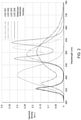
- FIG. 2 is a diagram of the spectra or spectral densities of several light-emitting devices configured to emit white light with reduced spectral content in the melanopic sensitivity range, as shown compared to the melanopic response function;
- FIG. 3 is a table showing spectral metrics for the light-emitting devices with spectra shown in FIG. 2 .
- the human circadian rhythm is a twenty-four hour cycle in the human physiological process and includes any biological process that displays an endogenous and entrainable oscillation.
- Entrainment is the interaction between circadian rhythms and the environment, such as the entrainment of circadian rhythms to the daily light-dark cycle determined by the earth's rotation.
- ipRGCs intrinsically photosensitive retinal ganglion cells
- light constricts the pupil, suppresses pineal melatonin production, increases heart rate and core body temperature, stimulates cortisol production, and acts as a neurophysiological stimulant.
- Empirical evidence has shown that these non-visual responses generally have a peak spectral sensitivity in the short-wavelength end of the visible spectrum. This correlates with the action spectrum for melanopsin, which is the photopigment (i.e., a pigment whose chemical state depends on its degree of illumination) in the eye expressed by the ipRGCs, and which peaks at a wavelength of 490 nm.
- the melanopic sensitivity range is 447-531 nm full width at half maximum (FWHM) (i.e., the width of the spectral density curve between points on the curve at which the spectral density reaches half its maximum value).
- the firing pattern of the ipRGCs is based not only on melanopsin phototransduction but also on inputs from rods and cones, due to their neurophysiological connections. Therefore, the spectral sensitivity of non-visual responses is generally more complex as it is affected by the total spectrum and illuminance (i.e., the amount of luminous flux per unit area) and may be different between specific physiological responses.
- Tools are available to calculate, for a given spectrum, the spectrally weighted irradiance (the flux of radiant energy per unit area) of the five human photopigments, which are well established. These tools can then be used as a starting point to study and quantify the ability of spectra to evoke non-visual responses.
- reducing the spectral content in the melanopic sensitivity range while maintaining a color point on the blackbody locus may involve moving to a deep-warm-white color.
- a deep-warm-white color LED is a 2200K/80 LED, which has 11% spectral power content in the melanopic range.
- a 2200K/80 LED is generally not desirable because of an undesirable color point (most applications specify light between 27000K and 4000K) and the much lower efficacy.
- Warm-white light sources need significant red to deep red spectral content to maintain good color rendering.
- the sensitivity of the human eye is relatively low and therefore the luminous efficacy (in units of lumens per Watt, lm/W) is low and inefficiencies are increased from emitting a spectrum where a large fraction of the emitted wavelengths are beyond the sensitivity of the human eye.
- a pc-LED with an emission spectrum that minimizes spectral content in the melanopic sensitivity range while still achieving a white color point with a CCT of 2700K or higher, allowing for high (luminous) efficacy.
- the disclosed pc-LED may be realized using a short-wavelength pump LED (e.g., a blue or violet LED) and a converter, coupled to and located above the short-wavelength pump LED, having a long-wavelength onset of the emission spectrum, thereby creating a cyan gap in the emitted spectrum coinciding with the melanopic range.
- An example of a converter is a phosphor layer or coating on or above the short-wavelength pump LED, such that the light (photons) generated by the LED travel through the phosphor layer.
- the disclosed pc-LED achieves a spectral power content in the melanopic range of approximately 5% while achieving a luminous efficacy of radiation (LER) that is improved by approximately 15% over a state-of-the-art 4000K/70 LED.
- LER luminous efficacy of radiation
- any other light source e.g., a laser diode
- converter quantum dot converter
- the disclosed light-emitting device is a violet or blue pc-LED (or laser diode) with a pump wavelength of 450 nm or less (e.g., 410-420 nm, 420-430 nm, 430-440 nm or 440-450 nm) and a total emission spectrum, once converted, that has a substantially white color point with a CCT of 2700K or higher, and a spectral power content in the 447-531 nm wavelength range of 10% or less of the total power between 380 nm and 780 nm.
- the disclosed light-emitting device may be an LED with a nitride-based phosphor system with peak emission in the amber wavelength range, which is approximately 570-600 nm.
- materials for the phosphor system may include, but is not limited to, (Ba,Sr) 2 Si 5 N 8 :Eu (“BSSN”), (Sr,Ca)SiAlN 3 :Eu (“SCASN”), a mixture of both BSSN and SCASN, and/or any phosphor with emission in the desired amber wavelength range.
- the disclosed LED may be a high-power flip-chip die and the phosphor may be integrated as a ceramic plate attached to the die.
- other pc-LED device architectures may similarly be employed.
- the disclosed light-emitting device may be incorporated in a light engine that also includes one or more light-emitters each with a cyan enhanced spectrum, and a control system that controls the drive current of the cyan depleted and cyan enhanced emitters.
- the control system may then be configured to suppress or evoke non-visual responses depending on application needs.
- FIG. 1 is a schematic diagram of an example light-emitting device 100 , in accordance with the disclosures herein.
- the light-emitting device 100 may be configured to provide white light 101 .
- the light-emitting device 100 may include a light source 102 configured to provide light source light 103 .
- the light source 102 may provide violet to blue light source light 103 , with a wavelength in the range of 400-460 nm (e.g., 410-450 nm).
- the light source 102 may be implemented as a pump LED, such as violet pump LED or a blue pump LED.
- the light source 102 may be high-power flip-chip die.
- the light-emitting device 100 may include a luminescent material element 104 .
- the luminescent material element 104 may include one or more converters, such as one or more narrow-band converters (e.g., quantum dot converters).
- the luminescent material element 104 may comprise down-converter(s) or down-converting material that converts high-energy photons provided by the light source 102 into lower-energy photons to constitute the rest of the spectrum.
- the luminescent material element 104 may be a nitride-based phosphor system and may consist of a phosphor material, such as any of the examples described herein.
- the luminescent material element 104 may be ceramic plate attached to the light source 102 .
- the luminescent material element 104 may be located downstream (in the direction of light emittance) of the light source 102 and in particular with respect to the light emitting surface 106 of the light source 102 .
- the material used in the luminescent material element 104 may be configured to absorb at least part of the light source light 103 (e.g., violet light or blue light) and may convert the light source light 103 into luminescent material light 105 .
- the luminescent material element 104 may be transmissive (i.e., allowing light to pass through) for at least part of the light source light 103 .
- the luminescent material element 104 may have waveguiding properties.
- the white light 101 emitted from the light-emitting device 100 may include at least some portion of the light source light 103 and at least some portion of the luminescent material light 105 .
- the luminescent material element 104 may include a luminescent material 110 , which provides the luminescent material light 105 .
- the luminescent material 110 is indicated as particles or regions within the luminescent material element 104 .
- the luminescent material 110 may be homogeneously distributed over the luminescent material element 104 .
- the luminescent material 110 may be consist of phosphor to provide a yellow light, and/or provide a broader combined emission spectrum extending into red light.
- the distance between the luminescent material element 104 and the light emitting surface 106 of the light source 102 is indicated by d 1 .
- the distance d 1 may be practically 0 mm (e.g., the luminescent material element 104 may be in physical contact with the light emitting surface 106 of the light source 102 , or separated by a transparent substrate or glue bond of only a few ⁇ m in thickness) or may be larger than 0 mm (e.g., 10 mm).
- the thickness d 2 of the luminescent material element 104 may be in the range of a 5 ⁇ m to 10 mm. The thickness d 2 may depend upon the type of application (e.g., thinner layer thicknesses for non-remote or vicinity applications, and larger layer thicknesses d 2 for remote applications).
- FIG. 2 is a diagram of the spectra or spectral densities (shown normalized in arbitrary units (a.u.)) of several light-emitting devices configured to emit white light with reduced spectral content in the melanopic sensitivity range, as shown compared to the melanopic response function (shown by a dashed line).
- Metrics for the spectra represented in FIG. 2 are given in FIG. 3 .
- the luminous efficacy of radiation (LER), measured in lumens per Watt (lm/W), is the ratio of luminous flux to power and provides a measure of how well a light source produces visible light.
- the CRI indicates, on a scale of 0-100, how accurately a given light source renders color when compared to a reference light source (CRI Ra refers to the average of the first eight indices defined in CRI).
- the light-emitting devices represented in FIG. 2 are: LED 201 (shown by a long dash/short dash line), which may be a state-of-the-art 4000K/70 LED; LED 202 (shown by a long dash/double short dash line), which may be an example 3000K pc-LED, as implemented in accordance with the disclosures herein; LED 203 (shown by a dotted line), which may be another example 3000K LED with further improved LER, as implemented in accordance with the disclosures herein; and LED 204 (shown by a solid line), which may be another example 3000K LED with improved CRI, as implemented in accordance with the disclosures herein.
- the spectral densities shown in FIG. 2 exhibit reduced melanopic illuminance (in the range of approximately 447-531 nm FWHM) at a given photopic illuminance.
- the example LEDs 202 , 203 and 204 implemented in accordance with the disclosures herein, have significantly higher LER (397 lm/W, 434 lm/W, and 382 lm/W, respectively) than the LER of the state-of-the-art 4000K/70 LED 201 (342 lm/W).
- the ceramic plate technology e.g., phosphor based
- the ceramic plate technology that may be used as a converter in the light-emitting device can reduce scattering compared to phosphor integration technologies using phosphor powder, which may further increase the overall luminous efficacy.
- the LED 203 and/or LED 204 may contain one or more narrow-band converters, for example quantum dot converters, to realize the respective desired spectrum shown in FIG. 2 .
- narrow-band converters for example quantum dot converters
- creating a cyan gap may desaturate cyan colors while oversaturating the violet-blue and green-yellow colors adjacent to the cyan gap.
- the impact on such saturation and desaturation on color rendering can be minimized and a CRI above 60 can be achieved while still maintaining minimal cyan content.
- the excellent color rendering at long wavelengths compensates for poorer color rendering of short wavelengths to achieve the acceptable overall CRI.
- FIG. 3 shows key spectral metrics for chromaticity, LER, color rendering (CRI) and melanopic spectral content for each of the LED light-emitter designs with spectra shown in FIG. 2 .
- the example LEDs 201 - 204 have small “Duv” values, which is the distance to the blackbody locus in CIE1976 color space, and thus indicate a white color for the example LEDs 201 - 204 .
- the example LEDs 202 , 203 and 204 implemented in accordance with the disclosures herein, have higher LER, and thus an improved luminous efficacy, than the LER of the state-of-the-art 4000K/70 LED 201 .
- TM-30 is a color rendering metric that consists of fidelity (TM-30 Rf), gamut (TM-30 Rg), and TM-30 color vector graphic showing saturation of individual colors.
- the melanopic spectral content may be represented by the fraction of radiometric power within the melanopic FWHM of 447-531 nm, or by the ratio of melanopic lux and photopic lux (m/p ratio). The latter more accurately reflects the weighting by the melanopic sensitivity curve.
Landscapes
- Chemical & Material Sciences (AREA)
- Engineering & Computer Science (AREA)
- Organic Chemistry (AREA)
- Materials Engineering (AREA)
- Inorganic Chemistry (AREA)
- Physics & Mathematics (AREA)
- Microelectronics & Electronic Packaging (AREA)
- General Engineering & Computer Science (AREA)
- Health & Medical Sciences (AREA)
- Optics & Photonics (AREA)
- Psychology (AREA)
- Anesthesiology (AREA)
- Animal Behavior & Ethology (AREA)
- General Health & Medical Sciences (AREA)
- Public Health (AREA)
- Veterinary Medicine (AREA)
- Hematology (AREA)
- Heart & Thoracic Surgery (AREA)
- Biomedical Technology (AREA)
- Life Sciences & Earth Sciences (AREA)
- Acoustics & Sound (AREA)
- Condensed Matter Physics & Semiconductors (AREA)
- General Physics & Mathematics (AREA)
- Electromagnetism (AREA)
- Led Device Packages (AREA)
- Luminescent Compositions (AREA)
- Non-Portable Lighting Devices Or Systems Thereof (AREA)
Abstract
Description
Claims (20)
Priority Applications (1)
| Application Number | Priority Date | Filing Date | Title |
|---|---|---|---|
| US16/332,319 US11230665B2 (en) | 2016-09-12 | 2017-09-12 | Lighting system having reduced melanopic spectral content |
Applications Claiming Priority (3)
| Application Number | Priority Date | Filing Date | Title |
|---|---|---|---|
| US201662393306P | 2016-09-12 | 2016-09-12 | |
| PCT/US2017/051170 WO2018049397A1 (en) | 2016-09-12 | 2017-09-12 | Lighting system having reduced melanopic spectral content |
| US16/332,319 US11230665B2 (en) | 2016-09-12 | 2017-09-12 | Lighting system having reduced melanopic spectral content |
Publications (2)
| Publication Number | Publication Date |
|---|---|
| US20190219234A1 US20190219234A1 (en) | 2019-07-18 |
| US11230665B2 true US11230665B2 (en) | 2022-01-25 |
Family
ID=59997436
Family Applications (2)
| Application Number | Title | Priority Date | Filing Date |
|---|---|---|---|
| US15/702,152 Active US10113700B2 (en) | 2016-09-12 | 2017-09-12 | Lighting system having reduced melanopic spectral content |
| US16/332,319 Active 2037-09-14 US11230665B2 (en) | 2016-09-12 | 2017-09-12 | Lighting system having reduced melanopic spectral content |
Family Applications Before (1)
| Application Number | Title | Priority Date | Filing Date |
|---|---|---|---|
| US15/702,152 Active US10113700B2 (en) | 2016-09-12 | 2017-09-12 | Lighting system having reduced melanopic spectral content |
Country Status (6)
| Country | Link |
|---|---|
| US (2) | US10113700B2 (en) |
| JP (1) | JP6883094B2 (en) |
| KR (1) | KR102253975B1 (en) |
| CN (1) | CN110024141B (en) |
| TW (1) | TWI756262B (en) |
| WO (1) | WO2018049397A1 (en) |
Families Citing this family (26)
| Publication number | Priority date | Publication date | Assignee | Title |
|---|---|---|---|---|
| US9410664B2 (en) | 2013-08-29 | 2016-08-09 | Soraa, Inc. | Circadian friendly LED light source |
| US10401683B2 (en) | 2015-01-14 | 2019-09-03 | Soraa, Inc. | Low blue light displays |
| US10837607B2 (en) * | 2017-09-26 | 2020-11-17 | Lumileds Llc | Light emitting device with improved warm-white color point |
| US10546843B2 (en) * | 2017-11-03 | 2020-01-28 | Ideal Industries Lighting Llc | White light emitting devices having high luminous efficiency and improved color rendering that include pass-through violet emissions |
| CN112088033B (en) | 2018-01-11 | 2024-05-03 | 生态照明公司 | Display lighting system with circadian effect |
| WO2019140309A1 (en) | 2018-01-11 | 2019-07-18 | Ecosense Lighting Inc. | Switchable systems for white light with high color rendering and biological effects |
| WO2019225247A1 (en) * | 2018-05-25 | 2019-11-28 | パナソニックIpマネジメント株式会社 | Daylighting control system, drive device, and drive method |
| WO2020043649A1 (en) * | 2018-08-31 | 2020-03-05 | Signify Holding B.V. | Cyan enriched white light |
| DE102018122283A1 (en) * | 2018-09-12 | 2020-03-12 | Osram Opto Semiconductors Gmbh | LIGHTING ARRANGEMENT |
| US12073775B2 (en) | 2018-11-08 | 2024-08-27 | Korrus, Inc. | Display lighting systems with bioactive lighting |
| US20220001200A1 (en) | 2018-11-08 | 2022-01-06 | Ecosense Lighting Inc. | Switchable bioactive lighting |
| US11783748B2 (en) | 2018-11-08 | 2023-10-10 | Korrus, Inc. | Display lighting systems with bioactive lighting |
| WO2020097596A1 (en) * | 2018-11-09 | 2020-05-14 | Li, Ying | Lighting device for horticulture |
| US11212890B2 (en) | 2019-01-25 | 2021-12-28 | Biological Innovation And Optimization Systems, Llc | Dual-mode spectral dimming lighting system |
| US10420184B1 (en) | 2019-01-25 | 2019-09-17 | Biological Innovation And Optimization Systems, Llc | Bio-dimming lighting system |
| US11145793B2 (en) * | 2019-05-09 | 2021-10-12 | Lumileds Llc | Light emitting diode with high melanopic spectral content |
| US10772169B1 (en) | 2019-05-28 | 2020-09-08 | Lumileds Llc | Wireless color tuning for constant-current driver |
| WO2021030272A1 (en) * | 2019-08-09 | 2021-02-18 | Ecosense Lighting Inc. | Led lighting channels having spectral power distribution characteristics and related multi-channel tunable white lighting systems |
| WO2021167100A1 (en) * | 2020-02-19 | 2021-08-26 | 京セラ株式会社 | Illumination device, illumination system, and illumination control method |
| JP2021163958A (en) * | 2020-03-31 | 2021-10-11 | 日亜化学工業株式会社 | Light emitting device and lighting equipment equipped with it |
| EP4130196A4 (en) * | 2020-03-31 | 2024-05-01 | Nichia Corporation | Light emission device and light fixture comprising same |
| US11982436B2 (en) | 2020-06-02 | 2024-05-14 | Signify Holding B.V. | Melanopic LED system with collimated white light and uncollimated cyan light |
| KR20220097816A (en) * | 2020-12-31 | 2022-07-08 | 삼성전자주식회사 | Led lighting apparatus |
| JP7706899B2 (en) | 2021-03-04 | 2025-07-14 | ソウル セミコンダクター カンパニー リミテッド | How to use a white light source and a white light source |
| WO2022209915A1 (en) * | 2021-03-31 | 2022-10-06 | 三井化学株式会社 | Optical element, glasses lens, autonomic nerve regulation method, and evaluation method for optical element |
| WO2023065536A1 (en) * | 2021-10-18 | 2023-04-27 | 佛山电器照明股份有限公司 | Rhythm spectrum modulation method |
Citations (16)
| Publication number | Priority date | Publication date | Assignee | Title |
|---|---|---|---|---|
| JP2007524119A (en) | 2004-01-15 | 2007-08-23 | ナノシス・インコーポレイテッド | Matrix doped with nanocrystals |
| US20090212698A1 (en) * | 2008-02-25 | 2009-08-27 | Bailey Edward E | Solid-state luminescent filament lamps |
| US20090281604A1 (en) | 2006-04-11 | 2009-11-12 | Koninklijke Philips Electronics N.V. | Controlling a photo-biological effect with light |
| US20110137757A1 (en) | 2008-06-26 | 2011-06-09 | Steven Paolini | Systems and Methods for Developing and Distributing Illumination Data Files |
| US20120019138A1 (en) | 2010-07-23 | 2012-01-26 | Maxik Fredric S | Led lamp for producing biologically-corrected light |
| US8251538B2 (en) | 2006-06-14 | 2012-08-28 | Koninklijke Philips Electronics N.V. | Lighting device |
| TW201307756A (en) | 2011-08-15 | 2013-02-16 | Appotronics Corp Ltd | Multicolor luminous device |
| US20140301062A1 (en) | 2009-09-18 | 2014-10-09 | Soraa, Inc. | Led lamps with improved quality of light |
| US20150062892A1 (en) * | 2013-08-29 | 2015-03-05 | Soraa, Inc. | Circadian friendly led light source |
| WO2015060701A1 (en) | 2013-10-22 | 2015-04-30 | Vilnius University | Photobiologically friendly phosphor converted light-emitting diode |
| US9024536B2 (en) | 2011-12-05 | 2015-05-05 | Biological Illumination, Llc | Tunable LED lamp for producing biologically-adjusted light and associated methods |
| US20150214444A1 (en) * | 2014-01-29 | 2015-07-30 | Nichia Corporation | Phosphor and light emitting device using the same |
| US20160116124A1 (en) | 2014-10-28 | 2016-04-28 | Soraa, Inc. | Light emitting diode device configured to change color during dimming |
| US20160377262A1 (en) * | 2010-02-03 | 2016-12-29 | Soraa, Inc. | System and method for providing color light sources in proximity to predetermined wavelength conversion structures |
| US20170368210A1 (en) * | 2016-06-24 | 2017-12-28 | Soraa, Inc. | Bactericidal light source with high quality of light |
| US20180128431A1 (en) | 2016-11-10 | 2018-05-10 | Energy Focus, Inc. | Led lamp utilizing optical filtering to counteract effects of color anomalous vision |
Family Cites Families (6)
| Publication number | Priority date | Publication date | Assignee | Title |
|---|---|---|---|---|
| US7361938B2 (en) | 2004-06-03 | 2008-04-22 | Philips Lumileds Lighting Company Llc | Luminescent ceramic for a light emitting device |
| US9039746B2 (en) | 2013-02-08 | 2015-05-26 | Cree, Inc. | Solid state light emitting devices including adjustable melatonin suppression effects |
| WO2015174322A1 (en) * | 2014-05-12 | 2015-11-19 | シャープ株式会社 | Light-emitting device and display apparatus |
| KR102544954B1 (en) | 2014-12-24 | 2023-06-20 | 루미리즈 홀딩 비.브이. | Phosphor conversion LED |
| CA3017104A1 (en) | 2015-03-09 | 2016-09-15 | Circadian Zirclight Inc. | Systems and methods for controlling environmental illumination |
| EP3271013B1 (en) | 2015-03-19 | 2018-08-22 | Philips Lighting Holding B.V. | Bio hue lamp |
-
2017
- 2017-09-12 KR KR1020197010397A patent/KR102253975B1/en active Active
- 2017-09-12 JP JP2019514001A patent/JP6883094B2/en active Active
- 2017-09-12 WO PCT/US2017/051170 patent/WO2018049397A1/en active Application Filing
- 2017-09-12 US US15/702,152 patent/US10113700B2/en active Active
- 2017-09-12 US US16/332,319 patent/US11230665B2/en active Active
- 2017-09-12 CN CN201780069765.2A patent/CN110024141B/en active Active
- 2017-09-12 TW TW106131180A patent/TWI756262B/en active
Patent Citations (19)
| Publication number | Priority date | Publication date | Assignee | Title |
|---|---|---|---|---|
| JP2007524119A (en) | 2004-01-15 | 2007-08-23 | ナノシス・インコーポレイテッド | Matrix doped with nanocrystals |
| US20090281604A1 (en) | 2006-04-11 | 2009-11-12 | Koninklijke Philips Electronics N.V. | Controlling a photo-biological effect with light |
| US8251538B2 (en) | 2006-06-14 | 2012-08-28 | Koninklijke Philips Electronics N.V. | Lighting device |
| US20090212698A1 (en) * | 2008-02-25 | 2009-08-27 | Bailey Edward E | Solid-state luminescent filament lamps |
| US20110137757A1 (en) | 2008-06-26 | 2011-06-09 | Steven Paolini | Systems and Methods for Developing and Distributing Illumination Data Files |
| US20140301062A1 (en) | 2009-09-18 | 2014-10-09 | Soraa, Inc. | Led lamps with improved quality of light |
| US20160377262A1 (en) * | 2010-02-03 | 2016-12-29 | Soraa, Inc. | System and method for providing color light sources in proximity to predetermined wavelength conversion structures |
| US20120019138A1 (en) | 2010-07-23 | 2012-01-26 | Maxik Fredric S | Led lamp for producing biologically-corrected light |
| TW201307756A (en) | 2011-08-15 | 2013-02-16 | Appotronics Corp Ltd | Multicolor luminous device |
| US9024536B2 (en) | 2011-12-05 | 2015-05-05 | Biological Illumination, Llc | Tunable LED lamp for producing biologically-adjusted light and associated methods |
| US20150062892A1 (en) * | 2013-08-29 | 2015-03-05 | Soraa, Inc. | Circadian friendly led light source |
| JP2015097196A (en) | 2013-08-29 | 2015-05-21 | ソラア インコーポレーテッドSoraa Inc. | Circadian friendly led light source |
| US9410664B2 (en) | 2013-08-29 | 2016-08-09 | Soraa, Inc. | Circadian friendly LED light source |
| WO2015060701A1 (en) | 2013-10-22 | 2015-04-30 | Vilnius University | Photobiologically friendly phosphor converted light-emitting diode |
| US20150214444A1 (en) * | 2014-01-29 | 2015-07-30 | Nichia Corporation | Phosphor and light emitting device using the same |
| JP2015163689A (en) | 2014-01-29 | 2015-09-10 | 日亜化学工業株式会社 | Phosphor and light emitting device using the same |
| US20160116124A1 (en) | 2014-10-28 | 2016-04-28 | Soraa, Inc. | Light emitting diode device configured to change color during dimming |
| US20170368210A1 (en) * | 2016-06-24 | 2017-12-28 | Soraa, Inc. | Bactericidal light source with high quality of light |
| US20180128431A1 (en) | 2016-11-10 | 2018-05-10 | Energy Focus, Inc. | Led lamp utilizing optical filtering to counteract effects of color anomalous vision |
Non-Patent Citations (2)
| Title |
|---|
| From the EPO as the ISA, International Search Report and Written Opinion, PCT/US2017/051170, dated Nov. 7, 2017, 10 pages. |
| International Search Report corresponding to PCT/US2017/051170, dated Nov. 7, 2017, 1 page. |
Also Published As
| Publication number | Publication date |
|---|---|
| US20190219234A1 (en) | 2019-07-18 |
| JP2019535129A (en) | 2019-12-05 |
| KR102253975B1 (en) | 2021-05-18 |
| CN110024141B (en) | 2022-02-15 |
| TW201821119A (en) | 2018-06-16 |
| JP6883094B2 (en) | 2021-06-09 |
| CN110024141A (en) | 2019-07-16 |
| WO2018049397A1 (en) | 2018-03-15 |
| TWI756262B (en) | 2022-03-01 |
| US20180073689A1 (en) | 2018-03-15 |
| US10113700B2 (en) | 2018-10-30 |
| KR20190047016A (en) | 2019-05-07 |
Similar Documents
| Publication | Publication Date | Title |
|---|---|---|
| US11230665B2 (en) | Lighting system having reduced melanopic spectral content | |
| US10837608B1 (en) | Full spectrum white light emitting devices | |
| KR102582473B1 (en) | Multi-channel lamp system and method with mixed spectrum | |
| JP6189217B2 (en) | White light source and white light source system using the same | |
| JP5622927B2 (en) | White light source | |
| US11574896B2 (en) | Full spectrum white light emitting devices | |
| US20160043288A1 (en) | Light-emitting diode module capable of reducing blue-light energy | |
| JP7274060B1 (en) | Melanopic light system with high CRI using cyan direct emitter | |
| WO2021007123A1 (en) | Full spectrum white light emitting devices | |
| JP5974394B2 (en) | White light emitting device and lighting apparatus using the same | |
| US11887973B2 (en) | Full spectrum white light emitting devices | |
| US12033990B2 (en) | Multi-color phosphor converted LED package with single cavity | |
| US20240325679A1 (en) | Low-blue light source | |
| CN118843763A (en) | Led filament with reduced optical crosstalk | |
| WO2020027783A1 (en) | Systems and methods for providing tunable warm white light | |
| CN108730779A (en) | A kind of adjustable color light source device | |
| JP2022070972A5 (en) | ||
| CN119816034A (en) | Full spectrum white light emitting device | |
| TW201304179A (en) | Apparatus and method for mixing LED light | |
| WO2019035832A1 (en) | Methods for generating tunable white light with high color rendering | |
| KR20140105902A (en) | Semiconductor light emitting device |
Legal Events
| Date | Code | Title | Description |
|---|---|---|---|
| FEPP | Fee payment procedure |
Free format text: ENTITY STATUS SET TO UNDISCOUNTED (ORIGINAL EVENT CODE: BIG.); ENTITY STATUS OF PATENT OWNER: LARGE ENTITY |
|
| STPP | Information on status: patent application and granting procedure in general |
Free format text: DOCKETED NEW CASE - READY FOR EXAMINATION |
|
| STPP | Information on status: patent application and granting procedure in general |
Free format text: NON FINAL ACTION MAILED |
|
| STPP | Information on status: patent application and granting procedure in general |
Free format text: FINAL REJECTION MAILED |
|
| STPP | Information on status: patent application and granting procedure in general |
Free format text: RESPONSE AFTER FINAL ACTION FORWARDED TO EXAMINER |
|
| STPP | Information on status: patent application and granting procedure in general |
Free format text: ADVISORY ACTION MAILED |
|
| STPP | Information on status: patent application and granting procedure in general |
Free format text: RESPONSE AFTER FINAL ACTION FORWARDED TO EXAMINER |
|
| STPP | Information on status: patent application and granting procedure in general |
Free format text: ADVISORY ACTION MAILED |
|
| STPP | Information on status: patent application and granting procedure in general |
Free format text: DOCKETED NEW CASE - READY FOR EXAMINATION |
|
| AS | Assignment |
Owner name: LUMILEDS LLC, CALIFORNIA Free format text: ASSIGNMENT OF ASSIGNORS INTEREST;ASSIGNORS:SOER, WOUTER A.;SHCHEKIN, OLEG B.;BECHTEL, HANS-HELMUT;SIGNING DATES FROM 20180222 TO 20180305;REEL/FRAME:057245/0286 |
|
| STPP | Information on status: patent application and granting procedure in general |
Free format text: AWAITING TC RESP., ISSUE FEE NOT PAID |
|
| STPP | Information on status: patent application and granting procedure in general |
Free format text: NOTICE OF ALLOWANCE MAILED -- APPLICATION RECEIVED IN OFFICE OF PUBLICATIONS |
|
| STPP | Information on status: patent application and granting procedure in general |
Free format text: PUBLICATIONS -- ISSUE FEE PAYMENT VERIFIED |
|
| STCF | Information on status: patent grant |
Free format text: PATENTED CASE |
|
| CC | Certificate of correction | ||
| AS | Assignment |
Owner name: DEUTSCHE BANK AG NEW YORK BRANCH, NEW YORK Free format text: PATENT SECURITY AGREEMENT;ASSIGNOR:LUMILEDS, LLC;REEL/FRAME:062114/0001 Effective date: 20221208 |
|
| AS | Assignment |
Owner name: SOUND POINT AGENCY LLC, NEW YORK Free format text: SECURITY INTEREST;ASSIGNORS:LUMILEDS LLC;LUMILEDS HOLDING B.V.;REEL/FRAME:062299/0338 Effective date: 20221230 |
|
| AS | Assignment |
Owner name: LUMILEDS HOLDING B.V., NETHERLANDS Free format text: RELEASE BY SECURED PARTY;ASSIGNOR:SOUND POINT AGENCY LLC;REEL/FRAME:070046/0001 Effective date: 20240731 Owner name: LUMILEDS LLC, CALIFORNIA Free format text: RELEASE BY SECURED PARTY;ASSIGNOR:SOUND POINT AGENCY LLC;REEL/FRAME:070046/0001 Effective date: 20240731 |
|
| AS | Assignment |
Owner name: LUMILEDS SINGAPORE PTE. LTD., SINGAPORE Free format text: ASSIGNMENT OF ASSIGNORS INTEREST;ASSIGNOR:LUMILEDS LLC;REEL/FRAME:071888/0086 Effective date: 20250708 |
|
| MAFP | Maintenance fee payment |
Free format text: PAYMENT OF MAINTENANCE FEE, 4TH YEAR, LARGE ENTITY (ORIGINAL EVENT CODE: M1551); ENTITY STATUS OF PATENT OWNER: LARGE ENTITY Year of fee payment: 4 |