US11229351B2 - Endoscope control unit with braking system - Google Patents
Endoscope control unit with braking system Download PDFInfo
- Publication number
- US11229351B2 US11229351B2 US16/542,942 US201916542942A US11229351B2 US 11229351 B2 US11229351 B2 US 11229351B2 US 201916542942 A US201916542942 A US 201916542942A US 11229351 B2 US11229351 B2 US 11229351B2
- Authority
- US
- United States
- Prior art keywords
- braking
- brake
- lid
- bushing
- shaft
- Prior art date
- Legal status (The legal status is an assumption and is not a legal conclusion. Google has not performed a legal analysis and makes no representation as to the accuracy of the status listed.)
- Active, expires
Links
Images


Classifications
-
- A—HUMAN NECESSITIES
- A61—MEDICAL OR VETERINARY SCIENCE; HYGIENE
- A61B—DIAGNOSIS; SURGERY; IDENTIFICATION
- A61B1/00—Instruments for performing medical examinations of the interior of cavities or tubes of the body by visual or photographical inspection, e.g. endoscopes; Illuminating arrangements therefor
- A61B1/005—Flexible endoscopes
- A61B1/0051—Flexible endoscopes with controlled bending of insertion part
- A61B1/0052—Constructional details of control elements, e.g. handles
-
- A—HUMAN NECESSITIES
- A61—MEDICAL OR VETERINARY SCIENCE; HYGIENE
- A61B—DIAGNOSIS; SURGERY; IDENTIFICATION
- A61B1/00—Instruments for performing medical examinations of the interior of cavities or tubes of the body by visual or photographical inspection, e.g. endoscopes; Illuminating arrangements therefor
- A61B1/00002—Operational features of endoscopes
- A61B1/00004—Operational features of endoscopes characterised by electronic signal processing
- A61B1/00006—Operational features of endoscopes characterised by electronic signal processing of control signals
-
- A—HUMAN NECESSITIES
- A61—MEDICAL OR VETERINARY SCIENCE; HYGIENE
- A61B—DIAGNOSIS; SURGERY; IDENTIFICATION
- A61B1/00—Instruments for performing medical examinations of the interior of cavities or tubes of the body by visual or photographical inspection, e.g. endoscopes; Illuminating arrangements therefor
- A61B1/00147—Holding or positioning arrangements
-
- A—HUMAN NECESSITIES
- A61—MEDICAL OR VETERINARY SCIENCE; HYGIENE
- A61B—DIAGNOSIS; SURGERY; IDENTIFICATION
- A61B1/00—Instruments for performing medical examinations of the interior of cavities or tubes of the body by visual or photographical inspection, e.g. endoscopes; Illuminating arrangements therefor
- A61B1/005—Flexible endoscopes
- A61B1/0051—Flexible endoscopes with controlled bending of insertion part
- A61B1/0057—Constructional details of force transmission elements, e.g. control wires
-
- A—HUMAN NECESSITIES
- A61—MEDICAL OR VETERINARY SCIENCE; HYGIENE
- A61B—DIAGNOSIS; SURGERY; IDENTIFICATION
- A61B1/00—Instruments for performing medical examinations of the interior of cavities or tubes of the body by visual or photographical inspection, e.g. endoscopes; Illuminating arrangements therefor
- A61B1/005—Flexible endoscopes
- A61B1/008—Articulations
-
- A—HUMAN NECESSITIES
- A61—MEDICAL OR VETERINARY SCIENCE; HYGIENE
- A61M—DEVICES FOR INTRODUCING MEDIA INTO, OR ONTO, THE BODY; DEVICES FOR TRANSDUCING BODY MEDIA OR FOR TAKING MEDIA FROM THE BODY; DEVICES FOR PRODUCING OR ENDING SLEEP OR STUPOR
- A61M25/00—Catheters; Hollow probes
- A61M25/01—Introducing, guiding, advancing, emplacing or holding catheters
- A61M25/0105—Steering means as part of the catheter or advancing means; Markers for positioning
- A61M25/0133—Tip steering devices
- A61M25/0136—Handles therefor
-
- A—HUMAN NECESSITIES
- A61—MEDICAL OR VETERINARY SCIENCE; HYGIENE
- A61M—DEVICES FOR INTRODUCING MEDIA INTO, OR ONTO, THE BODY; DEVICES FOR TRANSDUCING BODY MEDIA OR FOR TAKING MEDIA FROM THE BODY; DEVICES FOR PRODUCING OR ENDING SLEEP OR STUPOR
- A61M25/00—Catheters; Hollow probes
- A61M25/01—Introducing, guiding, advancing, emplacing or holding catheters
- A61M25/0105—Steering means as part of the catheter or advancing means; Markers for positioning
- A61M25/0133—Tip steering devices
- A61M25/0147—Tip steering devices with movable mechanical means, e.g. pull wires
-
- G—PHYSICS
- G02—OPTICS
- G02B—OPTICAL ELEMENTS, SYSTEMS OR APPARATUS
- G02B23/00—Telescopes, e.g. binoculars; Periscopes; Instruments for viewing the inside of hollow bodies; Viewfinders; Optical aiming or sighting devices
- G02B23/24—Instruments or systems for viewing the inside of hollow bodies, e.g. fibrescopes
- G02B23/2476—Non-optical details, e.g. housings, mountings, supports
-
- A—HUMAN NECESSITIES
- A61—MEDICAL OR VETERINARY SCIENCE; HYGIENE
- A61B—DIAGNOSIS; SURGERY; IDENTIFICATION
- A61B17/00—Surgical instruments, devices or methods, e.g. tourniquets
- A61B17/00234—Surgical instruments, devices or methods, e.g. tourniquets for minimally invasive surgery
- A61B2017/00292—Surgical instruments, devices or methods, e.g. tourniquets for minimally invasive surgery mounted on or guided by flexible, e.g. catheter-like, means
- A61B2017/003—Steerable
- A61B2017/00318—Steering mechanisms
- A61B2017/00323—Cables or rods
- A61B2017/00327—Cables or rods with actuating members moving in opposite directions
Definitions
- the present specification relates generally to endoscopes, and more specifically, to a control unit comprising a braking system for maneuvering the tip of an endoscope and fixing the tip at a desired position.
- An endoscope is a medical instrument used for examining and treating internal body parts such as the alimentary canals, airways, the gastrointestinal system, and other organ systems.
- Conventionally used endoscopes have at least a flexible tube carrying a fiber optic light guide for directing light from an external light source situated at a proximal end of the tube to a distal tip.
- most endoscopes are provided with one or more channels, through which medical devices, such as forceps, probes, and other tools, are passed.
- fluids such as water, saline, drugs, contrast material, dyes, or emulsifiers are often introduced or evacuated via the flexible tube.
- a plurality of channels, one each for introduction and suctioning of liquids, may be provided within the flexible tube.
- Endoscopes have attained great acceptance within the medical community since they provide a means for performing procedures with minimal patient trauma while enabling the physician to view the internal anatomy of the patient. Over the years, numerous endoscopes have been developed and categorized according to specific applications, such as cystoscopy, colonoscopy, laparoscopy, and upper GI endoscopy among others. Endoscopes are usually inserted into the body's natural orifices or through an incision in the skin.
- the distal end of an insertion tube is capable of being articulated by a steering mechanism that includes a pair of external control wheels coupled to steering cables mounted inside the insertion tube. Rotation of one of the control wheels produces an up or down deflection of the distal tip of the insertion tube while rotation of the second control wheel produces a left or right deflection of the insertion tube tip.
- a steering mechanism that includes a pair of external control wheels coupled to steering cables mounted inside the insertion tube.
- Rotation of one of the control wheels produces an up or down deflection of the distal tip of the insertion tube while rotation of the second control wheel produces a left or right deflection of the insertion tube tip.
- control wheels or knobs are locked through respective braking mechanisms, thereby causing the distal end of the insertion tube to be fixed in a desired position.
- German patent application DE 20 2011 109 769 UI discloses an endoscope having an articulation unit.
- the deflection of the articulation unit also called curvature device
- the distal end of the endoscope is effected by means of cables.
- two cables arranged opposite each other on the outer circumference of the articulation unit are connected to form a cable pair.
- the cable pairs are attached in such a way to cable drums that can be adjusted by rotary knobs so that the distal end of the articulation unit carries out a movement upwards or downwards (up/down; U-D) or a movement in a direction right or left (right/left; R-L).
- a locking device also called a brake, that prevents the cable drum(s) from rotating.
- a control unit for use with an endoscope for maneuvering the tip of a distal end of an endoscope insertion tube is provided.
- the endoscope tip is easily moved in up and down as well as right and left directions by using the control unit of the present specification.
- the control unit includes a braking system that allows for fixing the position of the endoscope tip.
- the present specification discloses a control unit providing a braking system for an articulation unit of endoscope, said control unit comprising: a first shaft having a first end and a second end, the first end being coupled with a first operating knob, the second end being coupled with a first cable drum and a first cable pair that are coupled with the articulation unit of the endoscope, wherein at least a portion of the first shaft in proximity to the first operating knob includes a space; a second hollow shaft having a first end and a second end, the first end being coupled with a second operating knob, the second end being coupled with a second cable drum and a second cable pair that are coupled with the articulation unit of the endoscope, wherein the first shaft is positioned within the second shaft; a brake knob rotatable about its center axis; a stationary sleeve arranged between the first and the second shafts; a spring supported by the first shaft in proximity to the first end of the first shaft; a pin extending into the space of the first shaft and coupled
- said pin includes at least two brake bodies.
- the predetermined direction may be a right/left (R/L) direction.
- the brake knob may be of concentric design and positioned above the first operating knob for braking the articulation unit in a predetermined direction.
- the pin is held in the second position by a latching mechanism.
- said latching mechanism comprises a control pin extending outwardly from said pin and a spiral groove having an upper portion and a lower portion with a recess formed in a wall of the first shaft.
- the control pin may be free to move within said spiral groove of said latching mechansim when said pin is in said first position.
- the control pin may be latched into said recess of said lower portion of said spiral groove when said pin is in said second position.
- a sealing element is provided between the first shaft and the first stationary sleeve.
- the present specification also discloses a control unit providing a braking system for an articulation unit of endoscope, said control unit comprising: a first shaft having a first end and a second end, the first end being coupled with a first operating knob, the second end being coupled with a first cable drum, a first cable pair, and the articulation unit of the endoscope, at least a portion of the first shaft in proximity of the first operating knob including a space; a second hollow shaft having a first end and a second end, the first end being coupled with a second operating knob, the second end being coupled with a second cable drum, a second cable pair, and the articulation unit of the endoscope, the first shaft is positioned within the second shaft; a brake disc having a central opening through which said second shaft extends, said brake disc being in physical contact with the second shaft; a stationary sleeve surrounding at least a portion of the second shaft; a brake base positioned below said brake disc, having a central opening through which said second shaft extends and comprising
- the predetermined direction may be an up/down (U/D) direction.
- the brake handle may be of concentric design and positioned below the second operating knob for braking the articulation unit in a predetermined direction.
- the brake brake base, lid, and bushing are supported by a housing surrounding the brake disc.
- the brake bushing comprises negative indentations on a surface for fitting into one or more positive indentations on a surface of the lid, compressing the brake bushing and the brake disc to the lid in the second position of the brake bushing.
- the negative indentations on the surface of the brake bushing are not aligned with the positive indentations on the surface of the lid and the brake disc is freely movable.
- an endoscope comprising a braking system for an articulation unit of the endoscope, said braking system comprising: a first shaft having a first end and a second end, the first end being coupled with a first operating knob, the second end being coupled with a first cable drum that is coupled with a first cable pair that is coupled with the articulation unit of the endoscope, at least a portion of the first shaft in proximity of the first operating knob having a space; a second hollow shaft having a first end and a second end, the first end being coupled with a second operating knob, the second end being coupled with a second cable drum that is coupled with a second cable pair that is coupled with the articulation unit of the endoscope, the first shaft is positioned within the second shaft; a right/left movement controller unit comprising: a brake knob rotatable about its center axis; a first stationary sleeve arranged between the first and the second shafts; a first spring being supported by the first shaft in proximity to the first end
- said braking system further comprises an up/down movement controller unit comprising: a brake disc having a central opening through which said second shaft extends, said brake disc being in physical contact with the second shaft; a second stationary sleeve surrounding at least a portion of the second shaft; a brake base positioned below said brake disc, having a central opening through which said second shaft extends and comprising a first control edge; a brake lid positioned above said brake base and said brake disc, coupled to said brake base, having a central opening through which said second shaft extends and comprising a second control edge; a second spring positioned between said brake base and said brake lid; a brake bushing positioned between said brake base and said brake lid and below said brake disc, having a central opening through which said second shaft extends and being movable vertically between first and second brake bushing positions; and a brake handle attached to said brake base for rotating said brake base and brake lid; wherein said brake bushing is movable from said first brake bushing position to said second brake bushing position by rotating said brake handle in
- the pin may be held in the second pin position by a latching mechanism.
- said latching mechanism comprises a control pin extending outwardly from said pin and a spiral groove having an upper portion and a lower portion with a recess formed in a wall of the first shaft.
- the control pin may be free to move within said spiral groove of said latching mechansim when said pin is in said first position and said control pin may be latched into said recess of said lower portion of said spiral groove when said pin is in said second position.
- a sealing element is provided between the first shaft and the first stationary sleeve.
- the brake bushing comprises negative indentations on a surface for fitting into one or more positive indentations on a surface of the lid, compressing the brake bushing and the brake disc to the lid in the second position of the brake bushing.
- the present specification also discloses a control unit providing a braking system for an articulation unit of endoscope, said control unit comprising: a first shaft having a first end and a second end, the first end being coupled with a first operating knob, the second end being coupled with a first cable drum and a first cable pair that are coupled with the articulation unit of the endoscope, wherein at least a portion of the first shaft in proximity to the first operating knob is hollow; a second hollow shaft having a first end and a second end, the first end being coupled with a second operating knob, the second end being coupled with a second cable drum and a second cable pair that are coupled with the articulation unit of the endoscope, wherein the first shaft is positioned within the second shaft; a brake knob rotatable about its center axis; a stationary sleeve arranged between the first and the second shafts; a spring supported by the first shaft in proximity to the first end of the first shaft; a pin extending into the hollow portion of the first shaft and coupled
- the predetermined direction is a right/left (R/L) direction.
- the brake knob is of concentric design and positioned above the first operating knob for braking the articulation unit in a predetermined direction.
- the pin is held in the second position by a latching mechanism.
- the latching mechanism comprises a control pin extending outwardly from said pin and a spiral groove having an upper portion and a lower portion with a recess formed in a wall of the first shaft.
- the control pin is free to move within said spiral groove of said latching mechanism when said pin is in said first position.
- the control pin is latched into said recess of said lower portion of said spiral groove when said pin is in said second position.
- a sealing element is provided between the first shaft and the first stationary sleeve.
- the present specification also discloses a control unit providing a braking system for an articulation unit of endoscope, said control unit comprising: a first shaft having a first end and a second end, the first end being coupled with a first operating knob, the second end being coupled with a first cable drum, a first cable pair, and the articulation unit of the endoscope, at least a portion of the first shaft in proximity of the first operating knob being hollow; a second hollow shaft having a first end and a second end, the first end being coupled with a second operating knob, the second end being coupled with a second cable drum, a second cable pair, and the articulation unit of the endoscope, the first shaft is positioned within the second shaft; a brake disc having a central opening through which said second shaft extends, said brake disc being in physical contact with the second shaft; a stationary sleeve surrounding at least a portion of the second shaft; a brake base positioned below said brake disc, having a central opening through which said second shaft extends and comprising a
- the predetermined direction is an up/down (U/D) direction.
- the brake handle is of concentric design and positioned below the second operating knob for braking the articulation unit in a predetermined direction.
- the brake brake base, lid, and bushing are supported by a housing surrounding the brake disc.
- the brake bushing comprises negative indentations on a surface for fitting into one or more positive indentations on a surface of the lid, compressing the brake bushing and the brake disc to the lid in the second position of the brake bushing.
- the negative indentations on the surface of the brake bushing are not aligned with the positive indentations on the surface of the lid and the brake disc is freely movable.
- an endoscope comprising a braking system for an articulation unit of the endoscope, said braking system comprising: a first shaft having a first end and a second end, the first end being coupled with a first operating knob, the second end being coupled with a first cable drum that is coupled with a first cable pair that is coupled with the articulation unit of the endoscope, at least a portion of the first shaft in proximity of the first operating knob being hollow; a second hollow shaft having a first end and a second end, the first end being coupled with a second operating knob, the second end being coupled with a second cable drum that is coupled with a second cable pair that is coupled with the articulation unit of the endoscope, the first shaft is positioned within the second shaft; a right/left movement controller unit comprising: a brake knob rotatable about its center axis; a first stationary sleeve arranged between the first and the second shafts; a first spring being supported by the first shaft in proximity to the first end;
- the pin is held in the second pin position by a latching mechanism.
- the latching mechanism comprises a control pin extending outwardly from said pin and a spiral groove having an upper portion and a lower portion with a recess formed in a wall of the first shaft.
- the control pin is free to move within said spiral groove of said latching mechanism when said pin is in said first position and said control pin is latched into said recess of said lower portion of said spiral groove when said pin is in said second position.
- a sealing element is provided between the first shaft and the first stationary sleeve.
- the brake bushing comprises negative indentations on a surface for fitting into one or more positive indentations on a surface of the lid, compressing the brake bushing and the brake disc to the lid in the second position of the brake bushing.
- the present specification describes a control unit providing a braking system for an articulation unit of an endoscope, said control unit comprising: a first shaft having a first end and a second end, the first end being coupled with a first operating knob, the second end being coupled with a first cable drum coupled with a first cable pair coupled with the articulation unit of the endoscope, at least a portion of the first shaft in proximity of the first operating knob being hollow; a second hollow shaft having a first end and a second end, the first end being coupled with a second operating knob, the second end being coupled with a second cable drum coupled with a second cable pair coupled with the articulation unit of the endoscope, the first shaft penetrating the second shaft; a first stationary sleeve arranged between the first and the second shafts; a brake body being radially displaceable in at least one radial opening made in a wall of the hollow portion of the first shaft; a spring being supported by the first shaft in proximity to the first end; and a
- the pin is mounted in the first shaft for countering the force of the spring.
- the pin is moved from the first position into the second position by one of a translation and a rotation motion.
- control unit further comprises a brake knob of concentric design positioned above the first operating knob for braking the articulation unit in a predetermined direction.
- the pin is held in the first position by a latching device comprising a control pin extending radially from the pin, the control pin being receivable in a spiral groove formed in a wall of the first shaft.
- a sealing element is provided between the first shaft and the first stationary sleeve.
- the present specification provides a control unit providing a braking system for an articulation unit of an endoscope, said control unit comprising: a first shaft having a first end and a second end, the first end being coupled with a first operating knob, the second end being coupled with a first cable drum coupled with a first cable pair coupled with the articulation unit of the endoscope, at least a portion of the first shaft in proximity of the first operating knob being hollow; a second hollow shaft having a first end and a second end, the first end being coupled with a second operating knob, the second end being coupled with a second cable drum coupled with a second cable pair coupled with the articulation unit of the endoscope, the first shaft penetrating the second shaft; a brake disc coupled with the second shaft; a stationary sleeve surrounding at least a portion of the second shaft, the stationary sleeve supporting a spring on a first control edge; a brake element comprising a second control edge being supported by the first control edge of the stationary slee
- control unit further comprises a brake knob of concentric design positioned above the second operating knob for braking the articulation unit in a predetermined direction.
- the brake element is supported by a housing surrounding the brake disc.
- the brake element comprises at least a brake bushing, a brake drum and a lid, the brake disc being positioned between the brake bushing and the lid, the brake bushing comprising negative indentations on a surface for fitting into one or more positive indentations on a surface of the lid compressing the brake bushing and the brake disc to the lid in the second position of the brake element.
- the negative indentations on the surface of the brake bushing are not aligned with the positive indentations on the surface of the lid and the brake disc is freely movable.
- control unit further comprises a brake handle being rotated from a first position to a second position for causing the brake element to move from the first position to the second position.
- FIG. 1 illustrates a perspective view of a distal end of a multi-viewing elements endoscope, in accordance with an embodiment of the present specification
- FIG. 2 illustrates a cross-sectional view of a bending section of a multi-viewing elements endoscope, in accordance with an embodiment of the present specification
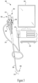
- FIG. 3 illustrates a multi-viewing elements endoscopy system, in accordance with an embodiment of the present specification
- FIG. 4A illustrates a cross-sectional view of a handle of an endoscope comprising a braking system, in accordance with an embodiment of the present specification
- FIG. 4B illustrates a close-up cross-sectional view of an alternative arrangement of a first shaft and a first stationary sleeve within a control unit, in accordance with an embodiment of the present specification
- FIG. 4C illustrates an enlarged cross-sectional view of the first shaft within the control unit depicted in FIG. 4B ;
- FIG. 4D illustrates a perspective view of the respective positions of three brake bodies within a first shaft, in accordance with some embodiments of the present specification
- FIG. 5A illustrates an embodiment of a latching mechanism incorporated in an endoscope braking system facilitating freewheeling and arrest operation for controlling the right-left movement of the endoscope tip, depicting a control pin in a first position;
- FIG. 5B illustrates the embodiment of the latching mechanism incorporated in an endoscope braking system of FIG. 5A , depicting the control pin in a second position;
- FIG. 6A illustrates cross-sectional side and top down views of one embodiment of a portion of a braking system for controlling an up-down (U-D) movement of an endoscope tip, depicting a brake handle in a first position;
- U-D up-down
- FIG. 6B illustrates cross-sectional side and top down views of the embodiment of a portion of a braking system for controlling an up-down (U-D) movement of an endoscope tip of FIG. 6A , depicting the brake handle in a second position;
- U-D up-down
- FIG. 6C illustrates cross-sectional side and top down views of one embodiment of a handle of an endoscope, depicting an up-down (U-D) braking system disengaged;
- FIG. 6D illustrates cross-sectional side and top down views of the embodiment of the handle of an endoscope of FIG. 6C , depicting the up-down (U-D) braking system engaged.
- the present specification discloses an endoscope having a tip section equipped with multiple viewing elements.
- a braking system for fixing a tip of the endoscope in a desired position is provided.
- the endoscope of the present specification comprises a handle from which an elongated shaft emerges.
- the elongated shaft terminates with a tip section which is turnable by way of a bending section.
- the endoscope comprises a plurality of steering cable eyes, positioned on the internal walls of the bending section. Through these eyes, steering cables are threaded to enable the maneuvering of the bending section comprising the tip of the endoscope.
- the handle is used for maneuvering the elongated shaft within a body cavity by means of one or more knobs which control the bending section.
- the braking system of the present specification ensures that a directional readjustment of right and left (or up and down) movement of the endoscope tip is possible. Further, the movement of the endoscope tip in the right-left direction or the up-down direction can be arrested using the braking system.
- a tip section 107 of the endoscope 100 includes therein a front-pointing viewing element 104 for capturing images through a hole in a distal end surface 106 of the tip section.
- a discrete front illuminator 108 which is, in an embodiment, a light-emitting diode (LED), is associated with front-pointing viewing element 104 and used for illuminating its field of view through another hole in distal end surface 106 .
- LED light-emitting diode
- a front fluid injector 110 is used for cleaning at least one of front-pointing viewing element 104 and discrete front illuminator 108 .
- front fluid injector 110 further includes a nozzle 110 e for directing fluid toward at least one of front-pointing viewing element 104 and discrete front illuminator 108 .
- Distal end surface 106 further includes a hole defining a working channel 112 , which may be a hollow tube configured for insertion of a surgical tool to operate on various tissues.
- a pathway fluid injector 114 defined by another hole in distal end surface 106 , is used for inflating and/or cleaning the body cavity into which endoscope 100 is inserted.
- Tip section 107 further comprises therein a side-pointing viewing element 116 used for capturing images through a hole in a cylindrical surface 105 of the tip section 107 .
- a discrete side illuminator 122 which is optionally similar to discrete front illuminator 108 , in one embodiment, is associated with side-pointing viewing element 116 and used for illuminating its field of view through another hole in cylindrical surface 105 .
- a side fluid injector 120 is used for cleaning at least one of side-pointing viewing element 116 and discrete side illuminator 122 .
- side fluid injector 120 further includes a nozzle 120 e for directing fluid toward at least one of side-pointing viewing element 116 and discrete side illuminator 122 .
- side fluid injector 120 and side-pointing viewing element 116 are located in a depression 118 in the cylindrical surface 105 .
- one or more discrete side illuminators may also be included in the depression, so that fluid injected from the side fluid injector reaches them.
- a side-pointing viewing element, one or more side illuminators and a side fluid injector may not be located in a depression, but rather be on essentially the same level as the cylindrical surface of the tip section. Further, in other embodiments, another side-pointing viewing element, one or more additional side illuminators, and another side fluid injector are positioned, within a depression or on the surface level, on another side or on the opposite side of the cylindrical surface from side pointing viewing element 116 .
- FIG. 2 shows a cross-sectional view of a bending section 200 of a multi-viewing elements endoscope, such as multi-viewing elements endoscope 100 of FIG. 1 .
- a plurality of steering cable eyes such as four eyes 208 , are positioned on the internal walls of bending section 200 . Through these eyes 208 , steering cables are threaded to enable the maneuvering of bending section 200 .
- Bending section 200 in an embodiment, comprises a working channel 202 , through which surgical tools are inserted, a fluid channel 206 , through which fluids and/or liquids are infused, and an electrical channel 204 with a plurality of electrical cables threaded through it, for transmitting video signals from the viewing elements and for supplying power to the viewing elements and the discrete illuminators.
- System 300 comprises a multi-viewing elements endoscope 302 .
- Multi-viewing elements endoscope 302 comprises a handle 304 from which an elongated shaft 306 emerges. Elongated shaft 306 terminates with a tip section 308 which is turnable by way of a bending section 310 .
- handle 304 is used for maneuvering elongated shaft 306 within a body cavity; the handle comprises one or more knobs and/or switches 305 which control bending section 310 as well as functions such as fluid injection and suction.
- Handle 304 further comprises a working channel opening 312 through which surgical tools are inserted.
- a utility cable 314 connects handle 304 and a controller 316 .
- Utility cable 314 comprises therein one or more fluid channels and one or more electrical channels.
- the electrical channel(s) comprises at least one data cable for receiving video signals from the front and side-pointing viewing elements, as well as at least one power cable for providing electrical power to the viewing elements and to the discrete illuminators.
- one or more input devices such as a keyboard 318 , is connected to controller 316 for the purpose of human interaction with the controller 316 .
- a display 320 is connected to controller 316 and configured to display images and/or video streams received from the viewing elements of multi-viewing elements endoscope 302 .
- FIG. 4A shows a cross section of an exemplary embodiment of a control unit 4010 for an endoscope.
- the control unit 4010 is incorporated into the handle of the endoscope.
- This example exhibits a locking or braking means for the movements right-left (R-L) as well as up-down (U-D).
- R-L right-left
- U-D up-down
- the control unit 4010 comprises a first shaft 4020 that is connected at its proximal end to a first operating knob 4030 . At its distal end, the shaft 4020 is connected to a first cable drum 4040 .
- the cable drum 4040 is attached to a first cable pair (not shown), which is further attached with an articulation unit (not shown) of the endoscope. As explained earlier, the deflection of the articulation unit can be controlled for manoeuvring and fixing the position of the endoscope tip.
- the first cable pair connected to the cable drum 4040 is arranged for moving the articulation unit in the direction R-L or U-D. If, for example, the first cable pair is arranged to provide a R-L movement, the corresponding movement of the articulation unit can be triggered by moving the first operating knob 4030 .
- At least a part of the first shaft 4020 is designed as a hollow shaft in the area of the first operating knob 4030 .
- at least one radial opening is provided in the wall of the hollow shaft, which is occupied by a brake body 4090 .
- the brake body 4090 can be shifted radially in the opening.
- a plurality of brake bodies 4090 is provided.
- a brake knob 4005 of concentric design is provided above the first operating knob 4030 .
- the brake knob 4005 is rotatable about its center axis.
- the braking system further comprises a first pin 4110 that extends into the hollow section of the first shaft 4020 .
- the first pin 4110 is mounted to counter the force of a first spring 4100 that is supported on the first shaft 4020 .
- the components are arranged relative to each other such that the first pin 4110 can be forced out of the hollow-shaft section by means of the first spring 4100 .
- the first pin 4110 further exhibits a tapered section 4115 that receives the brake body/bodies 4090 in a first position. This first position of the brake body 4090 is shown in FIG. 4A .
- the first pin 4110 can be moved from this first position into a second position by means of translation and/or rotation, counter to the force of the first spring 4100 that is supported on the first shaft 4020 .
- the first pin 4110 acts on the brake body 4090 in such a manner that it is partly forced downward through the opening of the shaft 4020 and is pressed against a first stationary sleeve 4080 that is arranged between the first shaft 4020 and a second shaft 4050 .
- This frictional connection between the brake body 4090 and the first stationary sleeve 4080 locks the first shaft 4020 , thus braking the articulation unit in the R-L direction. It would be appreciated that the setting of the articulation unit relative to the R-L direction can be readjusted or finally adjusted after braking by overcoming the friction of the brake body 4090 and the first stationary sleeve 4080 , wherein the level of the frictional force is predetermined by the pretension of the first spring 4100 that puts pressure on the first pin 4110 in an upward direction out of the hollow-shaft section.
- the first pin 4110 is held in the first position in a latching device that has to be overcome initially for the first pin 4110 to be brought into the second position. This allows the user operating the control unit to receive a touch-feedback on tightening and releasing the brake.
- FIG. 4B illustrates a close-up cross-sectional view of an alternative arrangement of a first shaft 4020 a and a first stationary sleeve 4080 a within a control unit 4010 a , in accordance with an embodiment of the present specification.
- FIG. 4C illustrates an expanded cross-sectional view of the first shaft 4020 a within the control unit 4010 a depicted in FIG. 4B .
- a first shaft 4020 a and a first stationary sleeve 4080 a arrangement are shown within control unit 4010 a .
- a proximal portion of first shaft 4020 a includes a space 4006 .
- space 4006 is configured to receive first pin 4110 a .
- the first pin 4110 a comprises an elongated member having an external surface area configured to be slidably received within space 4006 .
- First pin 4110 a is sized such that it is capable of rotating within space 4006 .
- first pin 4110 a further comprises a tapered section 4115 a that includes one or more pin openings 4002 a configured to receive brake body/bodies 4090 a in a first position.
- the section of the first pin including one or more pin openings is not tapered.
- FIG. 4B This first position of the brake body 4090 a is shown in FIG. 4B , wherein the braking mechanism is engaged.
- at least one radial shaft opening 4112 a is provided in the first shaft 4020 a , such that radial shaft opening 4112 a is aligned with pin opening 4002 a of pin 4110 a .
- radial shaft opening 4112 a is elongated and cylindrically shaped.
- the brake body 4090 a comprises an elongate member sized to fit within said radial shaft opening 4112 a .
- Brake body 4090 a may be perpendicularly aligned to the first shaft 4020 a and first pin 4110 a .
- Pin opening 4002 a may support the alignment of brake body 4090 a such that brake body 4090 a extends perpendicularly outwards from the first pin 4110 a .
- Brake body 4090 a can be shifted longitudinally and radially relative to the first stationary sleeve 4080 a.
- Rotational movement of the brake knob 4005 a in a first direction is translated into distal movement of the first pin 4110 a into space 4006 , resulting in the brake body/bodies 4090 a sliding within said radial shaft opening 4112 a and said pin opening 4002 a and shifting distally within said space 4006 .
- Rotational movement of the brake knob 4005 a in a second direction opposite said first direction moves allows the compression force of spring 4100 a to push said first pin 4110 a in a proximal direction, resulting in sliding movement and proximal movement of said brake body/bodies 4090 a away from said inner surface 4081 a , eliminating the contact between said brake body/bodies 4090 a and said sleeve 4080 a , thus disabling the braking mechanism.
- sleeve 4080 a is depicted in FIG. 4B as having a varying wall thickness, other embodiments are envisioned wherein sleeve 4080 a has a consistent wall thickness throughout its length, and wall thickness is not intended to contribute to the functioning of the braking mechanism.
- a plurality of brake bodies 4090 a is provided, each through a different shaft opening 4112 a and pin opening 4002 a .
- the central axis of any one of the three brake bodies 4090 a is positioned approximately 120 degrees from the central axis of the adjacent brake body 4090 a .
- FIG. 4D illustrates a perspective view of the respective positions of three brake bodies 4090 a within first shaft 4020 a , in accordance with some embodiments of the specification.
- Elongated brake bodies 4090 a extend radially outwards through pin openings 4002 a in the wall of first shaft 4020 a .
- the control unit includes two, three, or more brake bodies.
- brake body 4090 a is slightly elongated as compared to the brake body 4090 depicted in FIG. 4A .
- a width of the first shaft 4020 a is increased relative to a width of shaft 4020 of FIG. 4A to accommodate the longer brake bodies 4090 a .
- An elongated length 4004 of brake body 4090 a provides increased torque for braking.
- brake body 4090 may have a length in the range of 3-4 millimetres (mm).
- elongated brake body 4090 a may have a length between 4 to 10 mm, between 7 to 8 mm, or any other length in the range of 4 to 10 mm.
- Radial opening 4002 a within the wall of first shaft 4020 a extends along a thickness 4004 of wall of first shaft 4020 a .
- thickness 4004 must be sufficient to support the length of brake body 4090 a . Therefore, thickness 4004 may be similar to length of brake body 4090 a.
- FIGS. 5A and 5B illustrate a latching mechanism 5000 incorporated in the endoscope braking system for facilitating freewheeling and arrest operation for controlling the right-left movement of the endoscope tip, in accordance with an embodiment of the present specification.
- holding the first pin 5110 in the latching mechanism can be achieved by having a control pin 5113 that extends outwardly from an outer surface of the first pin 5110 .
- the control pin 5113 is received in a control section or groove 5114 that extends in a spiral form from a lower portion to an upper portion in the shaft 5020 and at the same time effects a rotation and a shift.
- the control section 5114 is formed as a guide introduced into the wall of the shaft 5020 .
- a recess 5115 is formed in the lower portion of the guide into which the control pin 5113 can latch on account of the force of the first spring and be pressed out again therefrom.
- FIGS. 5A and 5B illustrate a first and a second position of the control pin 5113 within the control section 5114 , respectively. Referring to FIG. 5A , the control pin 5113 is in the first position and free to move within the guide of the control section 5114 . When the control pin 5113 is in the first position, the first spring ( 4100 in FIG. 4 ) is relaxed, the shaft 5020 does not press against the first stationary sleeve ( 4080 in FIG.
- the control pin 5113 is in the second position, engaged within the recess 5115 of the control section 5114 .
- the first spring 4100 in FIG. 4
- the shaft 5020 is pressed against the first stationary sleeve ( 4080 in FIG. 4 )
- R-L braking is engaged.
- the control unit 4010 exhibits a second shaft 4050 that is connected at its proximal end to a second operating knob 4060 and at its distal end to a second cable drum 4070 for attaching a second cable pair (not shown) that is attached with the articulation unit (not shown).
- the cable pair that is connected to the second cable drum 4070 is designed to move the articulation unit in the direction U-D, such that a U-D movement of the articulation unit can be effected by moving the second operating knob 4060 .
- the second shaft 4050 is advantageously designed as a hollow shaft and the first shaft 4020 / 4020 a is positioned within, or penetrates, the second shaft 4050 , providing a concentric design. In various embodiments, a compact control unit is obtained due to this concentric design.
- the second operating knob 4060 exhibits a braking device wherein the second shaft 4050 is in contact with a brake disc 4120 .
- the brake disc 4120 can be fixed up to a predetermined desired degree by means of a frictional connection.
- At least a section of the second shaft 4050 is surrounded by a second stationary sleeve 4130 and a brake base 4075 (also seen in FIGS. 6A and 6B ) that exhibits a first control edge.
- a brake lid 4140 is provided that is mounted to counter the force of a second spring 4150 that is supported about the second stationary sleeve 4130 , and exhibits a second control edge that supports the second spring 4150 between itself and the first control edge of the base 4075 .
- a brake bushing 4195 is also positioned between the brake lid 4140 and brake base 4075 and can be brought from a first position into a second position by means of translation and/or rotation counter to the force of the spring 4150 that is supported on the second stationary sleeve 4130 .
- said translation and/or rotation is effectuated by rotation of a brake handle 4014 .
- the brake bushing 4195 in the first position does not produce any effect on the brake disc 4120
- the brake bushing 4195 exerts pressure on the brake disc 4120 and thus fixes the position of the second shaft 4050 .
- the braking process is particularly effective if the brake disc 4120 is clamped in between the brake lid 4140 and the second stationary sleeve 4130 , or if a further brake element is connected to it.
- This frictional connection between the brake disc 4120 and the brake lid 4140 and brake bushing 4195 locks the second shaft 4050 and thus the setting of the articulation unit in the U-D direction.
- the level of the frictional force is predetermined by the pretension of the second spring 4150 that presses the brake bushing 4195 against the brake disc 4120 .
- a sealing element exists between the first shaft 4020 / 4020 a and the first stationary sleeve 4080 / 4080 a . Also, since the brake lid 4140 is part of a housing that surrounds the brake disc 4120 , it is sealed using sealing means, so that both locking devices are protected against the ingress of moisture.
- control unit 4010 that is simple in design and watertight, and maintains a haptically recognisable separation between freewheeling and locking and is easy to operate.
- FIGS. 6A and 6B illustrate cross-sectional side views and top down views of a portion of the braking system of an endoscope causing a freewheeling and arrest operation of the endoscope tip in an up-down (U-D) direction, in accordance with an embodiment of the present specification.
- a brake bushing 6002 and a lid 6004 are shaped with negative indentations 6006 and positive indentations, or protrusions 6009 , respectively.
- a brake disc 6008 is positioned between the brake bushing 6002 and the lid 6004 and all the three parts are compressed by a second compression spring 6007 .
- a square head (not shown) connects the brake disc 6008 to a U-D control wheel, which enables the U-D movement of the endoscope tip.
- the square head is part of the U-D control wheel which fits into a square hole 6010 in the brake disc 6008 , operatively coupling the U-D control wheel and the brake disc 6008 .
- FIG. 6B illustrates the up-down braking system with the brake engaged.
- the brake handle 6014 includes a base 6015 which is screwed on to a brake drum 6016 and changes the position of the brake drum 6016 and lid 6004 relative to the brake bushing 6002 when rotated counter-clockwise.
- the protrusions 6009 slide into the negative indentations 6006 , the gap 6018 is eliminated and the brake bushing 6002 is compressed up to the lid 6004 by spring power of the second compression spring 6007 .
- a small gap 6018 between the brake disc 6008 and the lid 6004 is maintained during the freewheeling operation, allowing the brake disc 6008 to move freely.
- FIG. 6B the gap 6018 is eliminated and the brake disc 6008 is fixed to the lid 6004 when the braking effect is activated.
- FIG. 6C illustrates a cross-sectional side view and a top down view of a handle 6030 of an endoscope depicting one embodiment of an up-down (U-D) braking system disengaged.
- the brake handle 6014 is in its disengaged position and the protrusions of the lid are not aligned with the negative indentations 6006 of the bushing. In this configuration, the up-down control wheel 6012 is free to move.
- FIG. 6D illustrates a cross-sectional side view and a top down view of a handle 6030 of an endoscope depicting one embodiment of an up-down (U-D) braking system engaged.
- the brake handle 6014 has been rotated into its engaged position and the protrusions 6009 of the lid are snapped into the indentations of the bushing. In this configuration, the up-down control wheel 6012 is fixed.
- the U-D control wheel 6012 After the brake is actuated, it is still possible to move the U-D control wheel 6012 with slightly increased force and thus to bring the tip of a distal end of the endoscope into a desired position.
- the U-D knob in order to deactivate the braking effect and achieve the freewheeling operation, is rotated in a clockwise direction through a 40 degree angle and a force is applied, thereby causing the protrusions to snap out of the negative indentations.
- the present specification provides a braking system for use with an endoscope for maneuvering the tip of a distal end of an endoscope insertion tube.
- the endoscope tip may be easily moved in an up down as well as right left direction by using the braking system of the present specification.
- the braking system enables smooth transition between smooth directional readjustment of right and left (or up and down) movement of the insertion tube tip after applying brake for fixing the end position.
- the braking system provided is a watertight system that provides a complete separation between freewheeling and locking operations.
Abstract
Description
Claims (20)
Priority Applications (2)
| Application Number | Priority Date | Filing Date | Title |
|---|---|---|---|
| US16/542,942 US11229351B2 (en) | 2013-05-17 | 2019-08-16 | Endoscope control unit with braking system |
| US17/644,106 US11957311B2 (en) | 2021-12-14 | Endoscope control unit with braking system |
Applications Claiming Priority (6)
| Application Number | Priority Date | Filing Date | Title |
|---|---|---|---|
| US201361824634P | 2013-05-17 | 2013-05-17 | |
| US201361837108P | 2013-06-19 | 2013-06-19 | |
| US14/278,221 US20140343489A1 (en) | 2013-05-17 | 2014-05-15 | Endoscope Control Unit with Braking System |
| US14/835,996 US9949623B2 (en) | 2013-05-17 | 2015-08-26 | Endoscope control unit with braking system |
| US15/921,051 US10433715B2 (en) | 2013-05-17 | 2018-03-14 | Endoscope control unit with braking system |
| US16/542,942 US11229351B2 (en) | 2013-05-17 | 2019-08-16 | Endoscope control unit with braking system |
Related Parent Applications (1)
| Application Number | Title | Priority Date | Filing Date |
|---|---|---|---|
| US15/921,051 Continuation US10433715B2 (en) | 2013-05-17 | 2018-03-14 | Endoscope control unit with braking system |
Related Child Applications (1)
| Application Number | Title | Priority Date | Filing Date |
|---|---|---|---|
| US17/644,106 Continuation US11957311B2 (en) | 2021-12-14 | Endoscope control unit with braking system |
Publications (2)
| Publication Number | Publication Date |
|---|---|
| US20190365204A1 US20190365204A1 (en) | 2019-12-05 |
| US11229351B2 true US11229351B2 (en) | 2022-01-25 |
Family
ID=54835137
Family Applications (3)
| Application Number | Title | Priority Date | Filing Date |
|---|---|---|---|
| US14/835,996 Active 2034-06-19 US9949623B2 (en) | 2013-05-17 | 2015-08-26 | Endoscope control unit with braking system |
| US15/921,051 Active US10433715B2 (en) | 2013-05-17 | 2018-03-14 | Endoscope control unit with braking system |
| US16/542,942 Active 2034-08-05 US11229351B2 (en) | 2013-05-17 | 2019-08-16 | Endoscope control unit with braking system |
Family Applications Before (2)
| Application Number | Title | Priority Date | Filing Date |
|---|---|---|---|
| US14/835,996 Active 2034-06-19 US9949623B2 (en) | 2013-05-17 | 2015-08-26 | Endoscope control unit with braking system |
| US15/921,051 Active US10433715B2 (en) | 2013-05-17 | 2018-03-14 | Endoscope control unit with braking system |
Country Status (1)
| Country | Link |
|---|---|
| US (3) | US9949623B2 (en) |
Families Citing this family (46)
| Publication number | Priority date | Publication date | Assignee | Title |
|---|---|---|---|---|
| US9474440B2 (en) | 2009-06-18 | 2016-10-25 | Endochoice, Inc. | Endoscope tip position visual indicator and heat management system |
| US10524645B2 (en) | 2009-06-18 | 2020-01-07 | Endochoice, Inc. | Method and system for eliminating image motion blur in a multiple viewing elements endoscope |
| US10130246B2 (en) | 2009-06-18 | 2018-11-20 | Endochoice, Inc. | Systems and methods for regulating temperature and illumination intensity at the distal tip of an endoscope |
| US10663714B2 (en) | 2010-10-28 | 2020-05-26 | Endochoice, Inc. | Optical system for an endoscope |
| US9706908B2 (en) | 2010-10-28 | 2017-07-18 | Endochoice, Inc. | Image capture and video processing systems and methods for multiple viewing element endoscopes |
| US10517464B2 (en) | 2011-02-07 | 2019-12-31 | Endochoice, Inc. | Multi-element cover for a multi-camera endoscope |
| US10595714B2 (en) | 2013-03-28 | 2020-03-24 | Endochoice, Inc. | Multi-jet controller for an endoscope |
| US9636003B2 (en) | 2013-06-28 | 2017-05-02 | Endochoice, Inc. | Multi-jet distributor for an endoscope |
| JP6669647B2 (en) | 2013-05-07 | 2020-03-18 | エンドチョイス インコーポレイテッドEndochoice, Inc. | White balance correction device for use with endoscope and method of performing white balance correction |
| US9949623B2 (en) | 2013-05-17 | 2018-04-24 | Endochoice, Inc. | Endoscope control unit with braking system |
| US10064541B2 (en) | 2013-08-12 | 2018-09-04 | Endochoice, Inc. | Endoscope connector cover detection and warning system |
| US9943218B2 (en) | 2013-10-01 | 2018-04-17 | Endochoice, Inc. | Endoscope having a supply cable attached thereto |
| US9968242B2 (en) | 2013-12-18 | 2018-05-15 | Endochoice, Inc. | Suction control unit for an endoscope having two working channels |
| WO2015112747A2 (en) | 2014-01-22 | 2015-07-30 | Endochoice, Inc. | Image capture and video processing systems and methods for multiple viewing element endoscopes |
| US11234581B2 (en) | 2014-05-02 | 2022-02-01 | Endochoice, Inc. | Elevator for directing medical tool |
| EP3171752B1 (en) | 2014-07-21 | 2019-12-11 | EndoChoice, Inc. | Multi-focal, multi-camera endoscope systems |
| CN111990946A (en) | 2014-08-29 | 2020-11-27 | 恩多巧爱思股份有限公司 | System and method for varying the stiffness of an endoscope insertion tube |
| EP3235241B1 (en) | 2014-12-18 | 2023-09-06 | EndoChoice, Inc. | System for processing video images generated by a multiple viewing elements endoscope |
| WO2016112034A2 (en) | 2015-01-05 | 2016-07-14 | Endochoice, Inc. | Tubed manifold of a multiple viewing elements endoscope |
| US10376181B2 (en) | 2015-02-17 | 2019-08-13 | Endochoice, Inc. | System for detecting the location of an endoscopic device during a medical procedure |
| US10078207B2 (en) | 2015-03-18 | 2018-09-18 | Endochoice, Inc. | Systems and methods for image magnification using relative movement between an image sensor and a lens assembly |
| US10401611B2 (en) | 2015-04-27 | 2019-09-03 | Endochoice, Inc. | Endoscope with integrated measurement of distance to objects of interest |
| US10516865B2 (en) | 2015-05-17 | 2019-12-24 | Endochoice, Inc. | Endoscopic image enhancement using contrast limited adaptive histogram equalization (CLAHE) implemented in a processor |
| CN107613837B (en) * | 2015-06-02 | 2019-08-06 | 武汉佑康科技有限公司 | Self-locking angle-adjusting mechanism for endoscope |
| USD841159S1 (en) * | 2015-06-12 | 2019-02-19 | Fujifilm Corporation | Operating grip for endoscope |
| JP6845809B2 (en) * | 2015-08-11 | 2021-03-24 | ヒューマン エクステンションズ リミテッド | Control unit for flexible endoscopes |
| CN108430373B (en) | 2015-10-28 | 2022-05-27 | 安多卓思公司 | Apparatus and method for tracking the position of an endoscope within a patient |
| CN108697302B (en) | 2015-11-24 | 2021-07-27 | 安多卓思公司 | Disposable air/water and suction valve for endoscope |
| EP3419497B1 (en) | 2016-02-24 | 2022-06-01 | Endochoice, Inc. | Circuit board assembly for a multiple viewing element endoscope using cmos sensors |
| WO2017160792A1 (en) | 2016-03-14 | 2017-09-21 | Endochoice, Inc. | System and method for guiding and tracking a region of interest using an endoscope |
| US10993605B2 (en) | 2016-06-21 | 2021-05-04 | Endochoice, Inc. | Endoscope system with multiple connection interfaces to interface with different video data signal sources |
| US10588495B2 (en) | 2016-07-28 | 2020-03-17 | Cook Medical Technologies LL | Brake mechanism of a steerable catheter |
| WO2018088498A1 (en) * | 2016-11-10 | 2018-05-17 | 京セラオプテック株式会社 | Body cavity observation system, trocar device, and method of operating body cavity observation system |
| WO2018098465A1 (en) | 2016-11-28 | 2018-05-31 | Inventio, Inc. | Endoscope with separable, disposable shaft |
| US20220117466A1 (en) | 2018-11-30 | 2022-04-21 | Tso3 Inc. | Endoscopes With Improved Compatibility To Oxidative Processings And Methods For Manufacturing And Repairing The Same |
| CN111514422A (en) * | 2019-02-02 | 2020-08-11 | 李大庆 | Laryngeal mask operating assembly and mounting method and laryngeal mask |
| CN110384468B (en) * | 2019-06-04 | 2022-05-10 | 聚融医疗科技(杭州)有限公司 | Capsule endoscope |
| USD1018844S1 (en) | 2020-01-09 | 2024-03-19 | Adaptivendo Llc | Endoscope handle |
| EP3903662A1 (en) | 2020-04-30 | 2021-11-03 | Ambu A/S | An endoscope control system |
| US20210338050A1 (en) | 2020-04-30 | 2021-11-04 | Ambu A/S | Endoscope control system |
| EP4167892A1 (en) | 2020-06-19 | 2023-04-26 | Remedy Robotics, Inc. | Systems and methods for guidance of intraluminal devices within the vasculature |
| AU2022305235A1 (en) | 2021-07-01 | 2024-01-18 | Remedy Robotics, Inc. | Vision-based position and orientation determination for endovascular tools |
| US11707332B2 (en) | 2021-07-01 | 2023-07-25 | Remedy Robotics, Inc. | Image space control for endovascular tools |
| DE102021129717A1 (en) | 2021-11-15 | 2023-05-17 | Ambu A/S | Endoscope with adjustable braking mechanism |
| CN114176487A (en) * | 2021-12-07 | 2022-03-15 | 广州瑞派医疗器械有限责任公司 | Endoscope with a detachable handle |
| EP4306033A1 (en) * | 2022-07-13 | 2024-01-17 | Ambu A/S | Endoscope with cone brake |
Citations (336)
| Publication number | Priority date | Publication date | Assignee | Title |
|---|---|---|---|---|
| US4027697A (en) | 1975-11-19 | 1977-06-07 | Bonney Roland W | Rotary valve |
| US4084401A (en) | 1975-07-09 | 1978-04-18 | Hughes Aircraft Company | Digital watch with two buttons and improved setting and display control |
| US4402313A (en) | 1979-11-22 | 1983-09-06 | Olympus Optical Co., Ltd. | Endoscope light source device |
| US4461282A (en) | 1978-05-02 | 1984-07-24 | Kabushiki Kaisha Medos Kenkyusho | Mechanism for direction changing of endoscope top end |
| US4494549A (en) | 1981-05-21 | 1985-01-22 | Olympus Optical Co., Ltd. | Device for diagnosing body cavity interiors with supersonic waves |
| US4532918A (en) | 1983-10-07 | 1985-08-06 | Welch Allyn Inc. | Endoscope signal level control |
| US4588294A (en) | 1984-06-27 | 1986-05-13 | Warner-Lambert Technologies, Inc. | Searching and measuring endoscope |
| EP0202394A2 (en) | 1985-05-21 | 1986-11-26 | Dainichiseika Color & Chemicals Mfg. Co. Ltd. | Pigment composition |
| US4641635A (en) | 1984-08-15 | 1987-02-10 | Olympus Optical Co., Ltd. | Endoscope apparatus |
| US4727859A (en) | 1986-12-29 | 1988-03-01 | Welch Allyn, Inc. | Right angle detachable prism assembly for borescope |
| GB2196628A (en) | 1983-11-14 | 1988-05-05 | Dow Chemical Co | Intermediate substituted aniline derivatives |
| US4764801A (en) | 1985-10-08 | 1988-08-16 | Motorola Inc. | Poly-sidewall contact transistors |
| US4801792A (en) | 1986-03-22 | 1989-01-31 | Olympus Optical Co., Ltd. | Endoscope |
| US4825850A (en) | 1988-05-13 | 1989-05-02 | Opielab, Inc. | Contamination protection system for endoscope control handles |
| US4877314A (en) | 1987-05-25 | 1989-10-31 | Olympus Optical Co., Ltd. | Objective lens system for endoscopes |
| US4902115A (en) | 1986-09-22 | 1990-02-20 | Olympus Optical Co., Ltd. | Optical system for endoscopes |
| US4976522A (en) | 1988-05-02 | 1990-12-11 | Olympus Optical Co., Ltd. | Objective lens system for endoscopes |
| US4984878A (en) | 1988-09-29 | 1991-01-15 | Fuji Photo Optical Co., Ltd. | Ojective lens for endoscope |
| US5007406A (en) | 1988-11-04 | 1991-04-16 | Asahi Kogaku Kogyo Kabushiki Kaisha | Bending control device of endoscope |
| US5014685A (en) | 1988-07-13 | 1991-05-14 | Asahi Kogaku Kogyo Kabushiki Kaisha | Brake for bending control device of endoscope |
| US5193525A (en) | 1990-11-30 | 1993-03-16 | Vision Sciences | Antiglare tip in a sheath for an endoscope |
| US5224929A (en) | 1990-12-21 | 1993-07-06 | C. R. Bard, Inc. | Irrigation/aspiration cannula and valve assembly |
| US5298371A (en) | 1991-08-22 | 1994-03-29 | Fuji Photo Film Co., Ltd. | Method for processing a silver halide photographic light-sensitive material |
| US5359456A (en) | 1991-10-15 | 1994-10-25 | Olympus Optical Co., Ltd. | Objective lens system for endoscopes |
| US5395329A (en) | 1994-01-19 | 1995-03-07 | Daig Corporation | Control handle for steerable catheter |
| US5447148A (en) | 1993-07-08 | 1995-09-05 | Vision Sciences, Inc. | Endoscopic contamination protection system to facilitate cleaning of endoscopes |
| US5460167A (en) | 1993-03-04 | 1995-10-24 | Olympus Optical Co., Ltd. | Endoscope cover with channel |
| US5464007A (en) | 1994-02-23 | 1995-11-07 | Welch Allyn, Inc. | Fluid insensitive braking for an endoscope |
| US5489256A (en) | 1992-09-01 | 1996-02-06 | Adair; Edwin L. | Sterilizable endoscope with separable disposable tube assembly |
| US5518502A (en) | 1994-06-08 | 1996-05-21 | The United States Surgical Corporation | Compositions, methods and apparatus for inhibiting fogging of endoscope lenses |
| US5547457A (en) | 1993-01-22 | 1996-08-20 | Olympus Optical Co., Ltd. | Objective optical system for endoscopes |
| US5575755A (en) | 1994-02-23 | 1996-11-19 | Welch Allyn, Inc. | Fluid insensitive braking for an endoscope |
| US5587839A (en) | 1994-10-18 | 1996-12-24 | Fuji Photo Optical Co., Ltd. | Objective lens system for endoscope |
| US5630782A (en) | 1992-09-01 | 1997-05-20 | Adair; Edwin L. | Sterilizable endoscope with separable auxiliary assembly |
| US5662588A (en) | 1994-05-31 | 1997-09-02 | Olympus Optical Co., Ltd. | Endoscope apparatus |
| US5674182A (en) | 1993-02-26 | 1997-10-07 | Olympus Optical Co., Ltd. | Endoscope system including endoscope and protection cover |
| US5685823A (en) | 1994-03-30 | 1997-11-11 | Asahi Kogaku Kogyo Kabushiki Kaisha | End structure of endoscope |
| US5702347A (en) | 1993-01-27 | 1997-12-30 | Olympus Optical Co., Ltd. | Endoscope system including endoscope and disposable protection cover |
| US5707344A (en) | 1993-05-07 | 1998-01-13 | Olympus Optical Co., Ltd. | Endoscope |
| JPH1043129A (en) | 1996-08-02 | 1998-02-17 | Olympus Optical Co Ltd | Endoscope |
| US5725477A (en) | 1993-11-18 | 1998-03-10 | Asahi Kogaku Kogyo Kabushiki Kaisha | Front end structure of endoscope |
| US5725474A (en) | 1993-11-26 | 1998-03-10 | Asahi Kogaku Kogyo Kabushiki Kaisha | Front end structure of endoscope |
| US5725478A (en) | 1996-03-14 | 1998-03-10 | Saad; Saad A. | Methods and apparatus for providing suction and/or irrigation in a rigid endoscope while maintaining visual contact with a target area through the endoscope |
| US5725476A (en) | 1993-11-18 | 1998-03-10 | Asahi Kogaku Kogyo Kabushiki Kaisha | Front end structure of endoscope |
| US5777797A (en) | 1995-09-11 | 1998-07-07 | Fuji Photo Optical Co., Ltd. | Objective lens system for endoscopes having an image transfer optical fiber bundle |
| US5782751A (en) | 1994-05-26 | 1998-07-21 | Asahi Kogaku Kogyo Kabushiki Kaisha | Side view endoscope |
| JPH10239740A (en) | 1997-02-28 | 1998-09-11 | Toshiba Corp | Endoscope device |
| US5810715A (en) | 1995-09-29 | 1998-09-22 | Olympus Optical Co., Ltd. | Endoscope provided with function of being locked to flexibility of insertion part which is set by flexibility modifying operation member |
| US5836894A (en) | 1992-12-21 | 1998-11-17 | Artann Laboratories | Apparatus for measuring mechanical parameters of the prostate and for imaging the prostate using such parameters |
| US5860913A (en) | 1996-05-16 | 1999-01-19 | Olympus Optical Co., Ltd. | Endoscope whose distal cover can be freely detachably attached to main distal part thereof with high positioning precision |
| US5870234A (en) | 1996-09-06 | 1999-02-09 | Jos. Schneider Optische Werke Kreuznach Gmbh & Co. Kg | Compact wide-angle lens |
| JPH11137512A (en) | 1997-11-07 | 1999-05-25 | Toshiba Corp | Endoscopic equipment |
| US5916148A (en) | 1995-06-29 | 1999-06-29 | Olympus Optical Co., Ltd. | Objective optical system for endoscopes |
| US5940126A (en) | 1994-10-25 | 1999-08-17 | Kabushiki Kaisha Toshiba | Multiple image video camera apparatus |
| US6095970A (en) | 1997-02-19 | 2000-08-01 | Asahi Kogaku Kogyo Kabushiki Kaisha | Endoscope |
| US6117068A (en) | 1995-10-19 | 2000-09-12 | Elite Genetics, Inc | Artificial insemination system |
| US6181481B1 (en) | 1998-11-30 | 2001-01-30 | Fuji Photo Optical Co., Ltd. | Objective lens for endoscope |
| US6196967B1 (en) | 1998-03-18 | 2001-03-06 | Linvatec Corporation | Arthroscopic component joining system |
| CA2297886A1 (en) | 1999-12-08 | 2001-06-08 | Paccar Inc. | Extendable sleeper for a truck |
| US6261226B1 (en) | 1994-03-30 | 2001-07-17 | Medical Media Systems | Electronically Steerable Endoscope |
| US6277064B1 (en) | 1997-12-30 | 2001-08-21 | Inbae Yoon | Surgical instrument with rotatably mounted offset endoscope |
| US20010036322A1 (en) | 2000-03-10 | 2001-11-01 | Bloomfield John F. | Image processing system using an array processor |
| US20020017515A1 (en) | 2000-08-11 | 2002-02-14 | Asahi Kogaku Kogyo Kabushiki Kaisha | Method of manufacturing treatment instrument of endoscope |
| US6359674B1 (en) | 1999-06-08 | 2002-03-19 | Olympus Optical Co., Ltd. | Liquid crystal lens, liquid crystal lens unit, and liquid crystal lens assembly |
| US6375610B2 (en) | 1997-01-23 | 2002-04-23 | Fairmont Medical Products Pty. Ltd. | Endoscopic drape |
| US20020047897A1 (en) | 1999-12-17 | 2002-04-25 | Asahi Kogaku Kogyo Kabushiki Kaisha | Electronic endoscope selector |
| US6402738B1 (en) | 1999-02-04 | 2002-06-11 | Asahi Kogaku Kogyo Kabushiki Kaisha | Wire connection structure for endoscope |
| US20020087047A1 (en) | 1999-09-13 | 2002-07-04 | Visionscope, Inc. | Miniature endoscope system |
| US6419626B1 (en) | 1998-08-12 | 2002-07-16 | Inbae Yoon | Surgical instrument endoscope with CMOS image sensor and physical parameter sensor |
| US20020109774A1 (en) | 2001-01-16 | 2002-08-15 | Gavriel Meron | System and method for wide field imaging of body lumens |
| US20020161281A1 (en) | 2000-04-03 | 2002-10-31 | Ross Jaffe | Endoscope having a guide tube |
| US6476851B1 (en) | 1996-12-27 | 2002-11-05 | Olympus Optical Co., Ltd. | Electronic endoscope |
| US20020172498A1 (en) | 2001-05-18 | 2002-11-21 | Pentax Precision Instrument Corp. | Computer-based video recording and management system for medical diagnostic equipment |
| US20020183591A1 (en) | 2001-02-06 | 2002-12-05 | Nobuyuki Matsuura | Endoscopic system and method for positioning an indwelling tube |
| US20030030918A1 (en) | 2001-05-14 | 2003-02-13 | Asahi Kogaku Kogyo Kabushiki Kaisha | Endoscope objective optical system |
| US20030063398A1 (en) | 2001-09-28 | 2003-04-03 | Fuji Photo Optical Co., Ltd. | Electronic endoscope eliminating influence of light distribution in optical zooming |
| US20030076411A1 (en) | 2001-10-01 | 2003-04-24 | Pentax Corporation | Electronic endoscope with light-amount adjustment apparatus |
| US20030083552A1 (en) | 2001-10-19 | 2003-05-01 | Visionscope, Inc. | Miniature endoscope with imaging fiber system |
| US20030128893A1 (en) | 2001-11-19 | 2003-07-10 | Alfio Castorina | Method for merging digital images to obtain a high dynamic range digital image |
| US20030153897A1 (en) | 2002-02-12 | 2003-08-14 | Russo Ronald D. | Closed system drainage and infusion connector valve |
| US20030187328A1 (en) | 2002-03-29 | 2003-10-02 | Fuji Photo Optical Co., Ltd. | Endoscopic manual control knob, and a method for manufacturing same |
| US6638214B2 (en) | 2000-08-02 | 2003-10-28 | Fuji Photo Optical Co., Ltd. | Observation window washing device of endoscope |
| US6673012B2 (en) | 2000-04-19 | 2004-01-06 | Pentax Corporation | Control device for an endoscope |
| US20040015054A1 (en) | 2002-07-05 | 2004-01-22 | Kazuhiko Hino | Bending control mechanism for endoscope |
| US20040046865A1 (en) | 2001-05-16 | 2004-03-11 | Olympus Optical Co., Ltd. | Endoscope device, endoscope and image processing device for endoscope |
| US6712760B2 (en) | 2000-04-10 | 2004-03-30 | Pentax Corporation | Television device of portable endoscope |
| US20040061780A1 (en) | 2002-09-13 | 2004-04-01 | Huffman David A. | Solid-state video surveillance system |
| US20040106850A1 (en) | 2002-11-27 | 2004-06-03 | Olympus Corporation | Endoscope apparatus |
| US20040133072A1 (en) | 2002-09-13 | 2004-07-08 | Kennedy Bruce L. | Video recording and image capture device |
| US20040138532A1 (en) | 2001-05-20 | 2004-07-15 | Arkady Glukhovsky | Method for in vivo imaging of an unmodified gastrointestinal tract |
| US20040158129A1 (en) | 2003-02-10 | 2004-08-12 | Pentax Corporation | Endoscope |
| US20040160682A1 (en) | 2003-02-14 | 2004-08-19 | Hitoshi Miyano | Endoscope objective lens |
| US20040190159A1 (en) | 2003-03-28 | 2004-09-30 | Naoki Hasegawa | Endoscope image pickup unit for picking up magnified images of an object, a focus adjustment apparatus and method, and a focus range check apparatus and method for the same |
| JP2004313806A (en) * | 2004-08-04 | 2004-11-11 | Olympus Corp | Endoscope apparatus |
| US20040249247A1 (en) | 2003-05-01 | 2004-12-09 | Iddan Gavriel J. | Endoscope with panoramic view |
| US6832984B2 (en) | 1997-08-21 | 2004-12-21 | Paul Stelzer | Minimally invasive surgery device |
| US20050018042A1 (en) | 2003-01-07 | 2005-01-27 | Jean Rovegno | Video processor for endoscopy |
| US20050020876A1 (en) | 2000-04-20 | 2005-01-27 | Olympus Corporation | Operation microscope |
| US20050038317A1 (en) | 2004-10-11 | 2005-02-17 | Nitesh Ratnakar | Dual View Endoscope |
| US20050047134A1 (en) | 1997-08-26 | 2005-03-03 | Color Kinetics | Controlled lighting methods and apparatus |
| US20050090709A1 (en) | 2003-09-23 | 2005-04-28 | Olympus Corporation | Endoscope suitable to body cavity |
| US6888119B2 (en) | 2001-03-12 | 2005-05-03 | Olympus Corporation | Light scanning probe apparatus using light of low coherence |
| US20050119527A1 (en) | 2003-04-01 | 2005-06-02 | Scimed Life Systems, Inc. | Force feedback control system for video endoscope |
| JP2005253543A (en) | 2004-03-10 | 2005-09-22 | Pentax Corp | Water duct for endoscope |
| US20050234296A1 (en) | 2004-04-14 | 2005-10-20 | Usgi Medical Inc. | Method and apparatus for obtaining endoluminal access |
| US20050234347A1 (en) | 2004-03-29 | 2005-10-20 | Fujinon Corporation | Puncture-type endoscopic probe |
| US20050251127A1 (en) | 2003-10-15 | 2005-11-10 | Jared Brosch | Miniature ultrasonic transducer with focusing lens for intracardiac and intracavity applications |
| US20050272975A1 (en) | 2004-03-23 | 2005-12-08 | Mcweeney John O | In-vivo visualization system |
| US20050283048A1 (en) | 2001-10-19 | 2005-12-22 | Visionscope, Llc | Portable imaging system employing a miniature endoscope |
| JP2006025888A (en) | 2004-07-12 | 2006-02-02 | Forte Grow Medical Kk | Endoscope tube for water supply |
| US20060047184A1 (en) | 2004-08-26 | 2006-03-02 | Scimed Life Systems, Inc. | Endoscope having auto-insufflation and exsufflation |
| JP2006068109A (en) | 2004-08-31 | 2006-03-16 | Nagoya Institute Of Technology | Spherical capsule type omnidirectional endoscope |
| US20060063976A1 (en) | 2004-09-03 | 2006-03-23 | Sightline Technologies Ltd. | Optical head for endoscope |
| US20060069314A1 (en) | 2004-09-24 | 2006-03-30 | Mina Farr | Solid state illumination for endoscopy |
| US20060114986A1 (en) | 2004-09-30 | 2006-06-01 | Knapp Keith N Ii | Adapter for use with digital imaging medical device |
| US20060149129A1 (en) | 2005-01-05 | 2006-07-06 | Watts H D | Catheter with multiple visual elements |
| WO2006073676A1 (en) | 2004-12-30 | 2006-07-13 | Avantis Medical Systems, Inc. | Disposable multi-lumen catheter/sheath with reusable stylet/endoscope |
| US20060173245A1 (en) | 2005-01-28 | 2006-08-03 | Stryker Corporation | Disposable attachable light source unit for an endoscope |
| US20060171693A1 (en) | 2005-01-28 | 2006-08-03 | Stryker Corporation | Endoscope with integrated light source |
| EP1690497A1 (en) | 2003-12-02 | 2006-08-16 | Olympus Corporation | Ultrasonographic device |
| US20060184037A1 (en) | 2004-11-30 | 2006-08-17 | Can Ince | Pulsed lighting imaging systems and methods |
| US20060183975A1 (en) | 2004-04-14 | 2006-08-17 | Usgi Medical, Inc. | Methods and apparatus for performing endoluminal procedures |
| US20060189845A1 (en) | 2004-04-14 | 2006-08-24 | Usgi Medical Inc. | Methods and apparaus for off-axis visualization |
| US20060215406A1 (en) | 2005-02-18 | 2006-09-28 | William Thrailkill | Medical diagnostic instrument with highly efficient, tunable light emitting diode light source |
| US20060252994A1 (en) | 2005-05-06 | 2006-11-09 | Nitesh Ratnakar | Next Generation Colonoscope |
| US20060264704A1 (en) | 2004-01-19 | 2006-11-23 | Olympus Corporation | Capsule-type medical apparatus |
| US20060293556A1 (en) | 2005-05-16 | 2006-12-28 | Garner David M | Endoscope with remote control module or camera |
| US20070015989A1 (en) | 2005-07-01 | 2007-01-18 | Avantis Medical Systems, Inc. | Endoscope Image Recognition System and Method |
| US20070049803A1 (en) | 2004-04-27 | 2007-03-01 | Hiroki Moriyama | Endoscope and endoscope system |
| US20070055100A1 (en) | 2004-05-14 | 2007-03-08 | Takayuki Kato | Endoscope and endoscope apparatus |
| US20070079029A1 (en) | 2005-09-30 | 2007-04-05 | Symbol Technologies, Inc. | Processing image data from multiple sources |
| US20070088193A1 (en) | 2004-05-24 | 2007-04-19 | Koji Omori | Light source device for endoscope |
| US20070106119A1 (en) | 2005-06-29 | 2007-05-10 | Yasuo Hirata | Endoscope |
| US20070142711A1 (en) | 2005-12-13 | 2007-06-21 | Lex Bayer | Detachable Imaging Device, Endoscope Having A Detachable Imaging Device, And Method of Configuring Such An Endoscope |
| US20070162095A1 (en) | 2006-01-06 | 2007-07-12 | Ezc Medical Llc | Modular visualization stylet apparatus and methods of use |
| US20070167681A1 (en) | 2001-10-19 | 2007-07-19 | Gill Thomas J | Portable imaging system employing a miniature endoscope |
| US20070177009A1 (en) | 2005-01-05 | 2007-08-02 | Avantis Medical Systems, Inc. | Endoscope assembly with a polarizing filter |
| US20070177008A1 (en) | 2005-01-05 | 2007-08-02 | Avantis Medical, Inc. | Endoscope with an imaging catheter assembly and method of configuring an endoscope |
| WO2007087421A2 (en) | 2006-01-23 | 2007-08-02 | Avantis Medical Systems, Inc. | Endoscope |
| WO2007092636A2 (en) | 2006-02-09 | 2007-08-16 | Avantis Medical Systems, Inc. | Endoscope assembly with a polarizing filter |
| WO2007092533A2 (en) | 2006-02-06 | 2007-08-16 | Avantis Medical Systems, Inc. | Endoscope with an imaging catheter assembly and method of configuring an endoscope |
| US20070188427A1 (en) | 1997-12-17 | 2007-08-16 | Color Kinetics Incorporated | Organic light emitting diode methods and apparatus |
| US20070197875A1 (en) | 2003-11-14 | 2007-08-23 | Osaka Shoji | Endoscope device and imaging method using the same |
| US20070203396A1 (en) | 2006-02-28 | 2007-08-30 | Mccutcheon John G | Endoscopic Tool |
| US20070206945A1 (en) | 2006-03-01 | 2007-09-06 | Delorme David M | Method and apparatus for panoramic imaging |
| US20070213591A1 (en) | 2005-09-06 | 2007-09-13 | Stryker Gi Ltd. | Disposable Cap for Endoscope |
| US20070229656A1 (en) | 2006-03-27 | 2007-10-04 | Semion Khait | Battery contacts for an in-vivo imaging device |
| US20070244353A1 (en) | 2006-04-13 | 2007-10-18 | Larsen Dane M | Resectoscopic Device And Method |
| US20070244354A1 (en) | 2006-04-18 | 2007-10-18 | Avantis Medical Systems, Inc. | Vibratory Device, Endoscope Having Such A Device, Method For Configuring An Endoscope, And Method Of Reducing Looping Of An Endoscope. |
| US20070247867A1 (en) | 2006-04-21 | 2007-10-25 | Sunoptic Technologies Llc | Portable LED Light Source for an Endoscope or Boroscope |
| US20070265492A1 (en) | 2004-06-07 | 2007-11-15 | Elazar Sonnenschein | Multipurpose Endoscopy Suite |
| US20070270642A1 (en) | 2006-05-19 | 2007-11-22 | Avantis Medical Systems, Inc. | System and method for producing and improving images |
| US20070293720A1 (en) | 2005-01-05 | 2007-12-20 | Avantis Medical Systems, Inc. | Endoscope assembly and method of viewing an area inside a cavity |
| US20080021274A1 (en) | 2005-01-05 | 2008-01-24 | Avantis Medical Systems, Inc. | Endoscopic medical device with locking mechanism and method |
| US20080025413A1 (en) | 2006-07-28 | 2008-01-31 | John Apostolopoulos | Selecting bit rates for encoding multiple data streams |
| WO2008015164A1 (en) | 2006-08-01 | 2008-02-07 | Varioptic | Liquid lens with four liquids |
| US20080036864A1 (en) | 2006-08-09 | 2008-02-14 | Mccubbrey David | System and method for capturing and transmitting image data streams |
| US20080045797A1 (en) | 2004-07-02 | 2008-02-21 | Osaka University | Endoscope Attachment And Endoscope |
| US20080058601A1 (en) | 2004-01-19 | 2008-03-06 | Olympus Corporation | Endoscopic imaging apparatus and capsule-type endoscope |
| US20080071290A1 (en) | 2006-06-13 | 2008-03-20 | Intuitive Surgical, Inc. | Minimally invasive surgery instrument assembly with reduced cross section |
| US20080130108A1 (en) | 2005-01-05 | 2008-06-05 | Avantis Medical Systems, Inc. | Endoscope assembly with a polarizing filter |
| US20080151070A1 (en) | 2006-12-26 | 2008-06-26 | Canon Kabushiki Kaisha | Image capture and display control apparatus, image capture and display control method, and image capture and display system |
| US20080161646A1 (en) | 2006-01-30 | 2008-07-03 | New Wave Surgical Corp. | Device For White Balancing And Appying An Anti-Fog Agent To Medical Videoscopes Prior To Medical Procedures |
| US20080167529A1 (en) | 2005-03-15 | 2008-07-10 | Takashi Otawara | Endoscope Insertion Portion |
| US20080163652A1 (en) | 2007-01-04 | 2008-07-10 | Leonid Shatskin | Safing lock mechanism |
| US20080177139A1 (en) | 2007-01-19 | 2008-07-24 | Brian Courtney | Medical imaging probe with rotary encoder |
| US20080183043A1 (en) | 2007-01-30 | 2008-07-31 | Fraunhofer-Gesellschaft Zur Forderung Der Angewandten Forschung E.V. | Illumination apparatus for an image sensing means at the distal end of an endoscope |
| US20080183034A1 (en) | 2007-01-31 | 2008-07-31 | Stryker Gi Ltd. | Endoscope Stand |
| US20080221388A1 (en) | 2007-03-09 | 2008-09-11 | University Of Washington | Side viewing optical fiber endoscope |
| US7435218B2 (en) | 2001-04-27 | 2008-10-14 | Storz Endoskop Gmbh | Optical instrument, in particular an endoscope, having an interchangeable head |
| US20080253686A1 (en) | 2007-04-10 | 2008-10-16 | Avantis Medical Systems, Inc. | Method and Device for Examining or Imaging an Interior Surface of a Cavity |
| US20080262312A1 (en) | 2007-04-17 | 2008-10-23 | University Of Washington | Shadowing pipe mosaicing algorithms with application to esophageal endoscopy |
| EP1986541A2 (en) | 2006-01-23 | 2008-11-05 | Avantis Medical Systems, Inc. | Endoscope |
| US20080275298A1 (en) | 2004-10-11 | 2008-11-06 | Novation Science, Llc | Dual View Endoscope |
| US20080303898A1 (en) | 2007-06-06 | 2008-12-11 | Olympus Medical Systems Corp. | Endoscopic image processing apparatus |
| US20090005643A1 (en) | 2007-06-27 | 2009-01-01 | Syntheon Llc | Torque-transmitting, variably-flexible, locking insertion device and method for operating the insertion device |
| US20090023998A1 (en) | 2007-07-17 | 2009-01-22 | Nitesh Ratnakar | Rear view endoscope sheath |
| US20090030275A1 (en) | 2005-09-28 | 2009-01-29 | Imperial Innovations Limited | Imaging System |
| WO2009015396A2 (en) | 2007-07-26 | 2009-01-29 | Avantis Medical Systems, Inc. | Endoscope system |
| US20090054790A1 (en) | 2006-02-23 | 2009-02-26 | Jurgen Czaniera | Method and Arrangement for Generating a Signal which Corresponds to the Degree of Opening of the Vocal Folds of the Larynx |
| US20090062615A1 (en) | 2007-08-31 | 2009-03-05 | Koji Yamaya | Endoscope with focal length varying function |
| US20090086017A1 (en) | 2007-09-27 | 2009-04-02 | Hitoshi Miyano | Imaging optical system and endoscope imaging apparatus |
| WO2009049322A2 (en) | 2007-10-11 | 2009-04-16 | Avantis Medical Systems, Inc. | Endoscope assembly comprising retrograde viewing imaging device and instrument channel |
| WO2009049324A1 (en) | 2007-10-11 | 2009-04-16 | Avantis Medical Systems, Inc. | Method and device for reducing the fixed pattern noise of a digital image |
| US20090135245A1 (en) | 2007-11-27 | 2009-05-28 | Jiafu Luo | Camera system with multiple pixel arrays on a chip |
| US20090137875A1 (en) | 2005-09-22 | 2009-05-28 | Hideya Kitagawa | Endoscope insertion portion |
| US20090143647A1 (en) | 2007-12-03 | 2009-06-04 | Olympus Medical Systems Corp. | Medical appliance, endoscope overtube, and endoscope apparatus |
| US20090147076A1 (en) | 2007-12-10 | 2009-06-11 | Hasan Ertas | Wide angle HDTV endoscope |
| US20090182917A1 (en) | 2008-01-15 | 2009-07-16 | Kim Jechan | System having capability for daisy-chained serial distribution of video display data |
| US20090216084A1 (en) | 2008-02-26 | 2009-08-27 | Kenji Yamane | Endoscopic aspiration device |
| US20090231419A1 (en) | 2007-02-06 | 2009-09-17 | Avantis Medical Systems, Inc. | Endoscope Assembly and Method of Performing a Medical Procedure |
| US20090234183A1 (en) | 2008-03-11 | 2009-09-17 | Kazunori Abe | Endoscope system and method for inspecting electronic endoscope |
| US20090253966A1 (en) | 2005-05-11 | 2009-10-08 | Hironobu Ichimura | Distal end portion of endoscope |
| US20090287192A1 (en) | 2005-04-01 | 2009-11-19 | Vivenzio Robert L | Medical diagnostic instrument having portable illuminator |
| US20090287188A1 (en) | 2008-05-13 | 2009-11-19 | Boston Scientific Scimed, Inc. | Steering system with locking mechanism |
| US20090299144A1 (en) | 2006-11-24 | 2009-12-03 | Olympus Medical Systems Corp. | Capsule endoscope |
| US20100010309A1 (en) | 2008-07-14 | 2010-01-14 | Olympus Corporation | Endoscope bend tube and endoscope including the bend tube |
| US20100016673A1 (en) | 2008-02-12 | 2010-01-21 | Innurvation, Inc. | Ingestible Endoscopic Optical Scanning Device |
| US20100053312A1 (en) | 2006-11-28 | 2010-03-04 | Olympus Corporation | Endoscope apparatus |
| US20100073470A1 (en) | 2008-09-22 | 2010-03-25 | Fujifilm Corporation | Imaging apparatus and endoscope |
| US20100076268A1 (en) | 2008-09-19 | 2010-03-25 | Olympus Medical Systems Corp. | Endoscope for oblique viewing |
| US20100073948A1 (en) | 2008-09-24 | 2010-03-25 | Code 3, Inc. | Light bar |
| US7701650B2 (en) | 2007-08-23 | 2010-04-20 | Hon Hai Precision Industry Co., Ltd. | Wide-angle lens module and endoscope |
| US7713246B2 (en) | 2002-10-28 | 2010-05-11 | Covidien Ag | Automatic valve |
| US20100123950A1 (en) | 2008-11-19 | 2010-05-20 | Olympus Corporation | Objective optical system |
| US20100130822A1 (en) | 2007-06-22 | 2010-05-27 | Olympus Medical Systems Corp. | Capsule-type medical device and method of monitoring esophagus inside and stomach inside, method of monitoring stomach inside and method of washing stomach using the same |
| US20100141763A1 (en) | 2008-12-04 | 2010-06-10 | Masaya Itoh | Video monitoring system |
| US20100160729A1 (en) | 2008-12-19 | 2010-06-24 | Smith Paul J | Systems and methods for directing instruments to varying positions at the distal end of a guide tube |
| US7746572B2 (en) | 2007-08-21 | 2010-06-29 | Fujinon Corporation | Imaging lens and image pickup apparatus |
| US20100174144A1 (en) | 2007-06-08 | 2010-07-08 | Thomas Hsu | Devices and methods for removal of debris from the objective lens of an endoscope |
| JP2010178766A (en) | 2009-02-03 | 2010-08-19 | Hoya Corp | Endoscope for treatment |
| US20100231702A1 (en) | 2007-09-28 | 2010-09-16 | Fujifilm Corporation | Image pickup device and endoscope provided with image pickup device |
| US20100249513A1 (en) | 2009-03-31 | 2010-09-30 | Jay Tydlaska | Laryngoscope and system |
| US20100245653A1 (en) | 2008-01-14 | 2010-09-30 | Integrated Medical Systems International, Inc. | Endoscope Objective Lens and Method of Assembly |
| US7813047B2 (en) | 2006-12-15 | 2010-10-12 | Hand Held Products, Inc. | Apparatus and method comprising deformable lens element |
| US20100280322A1 (en) | 2008-06-04 | 2010-11-04 | Fujifilm Corporation | Illumination device for use in endoscope |
| US7828725B2 (en) | 2006-04-26 | 2010-11-09 | Hoya Corporation | Bent state holding mechanism of an endoscope |
| US7830148B2 (en) | 2007-09-12 | 2010-11-09 | Hitachi, Ltd. | NMR sample tube |
| US20100296178A1 (en) | 2006-05-05 | 2010-11-25 | Magalie Genet | Miniaturized optical head with high spatial resolution and high sensitivity, especially for fibred confocal fluorescence imaging |
| WO2010146587A1 (en) | 2009-06-18 | 2010-12-23 | Peer Medical Ltd. | Multi-camera endoscope |
| US20110034769A1 (en) | 1997-10-06 | 2011-02-10 | Micro-Imaging Solutions Llc | Reduced area imaging device incorporated within wireless endoscopic devices |
| US20110063427A1 (en) | 2008-03-18 | 2011-03-17 | Novadaq Technologies Inc. | Imaging system for combined full-color reflectance and near-infrared imaging |
| US7927272B2 (en) | 2006-08-04 | 2011-04-19 | Avantis Medical Systems, Inc. | Surgical port with embedded imaging device |
| DE202010016900U1 (en) | 2010-12-22 | 2011-05-19 | Peer Medical Ltd. | Multi-camera endoscope |
| US20110140003A1 (en) | 2009-12-16 | 2011-06-16 | Gerd Beck | Test apparatus for an optical investigation system |
| US7967745B2 (en) | 2006-09-28 | 2011-06-28 | Given Imaging, Ltd. | In vivo imaging device and method of manufacture thereof |
| US20110160530A1 (en) | 2004-10-11 | 2011-06-30 | Nitesh Ratnakar | Next Generation Endoscope |
| US7978462B2 (en) | 2008-05-09 | 2011-07-12 | Fujitsu Ten Limited | Electronic apparatus |
| US20110168831A1 (en) | 2005-12-14 | 2011-07-14 | Sca Hygiene Products Ab | Dispenser loading arrangement and method of loading a dispenser |
| US20110184243A1 (en) | 2009-12-22 | 2011-07-28 | Integrated Endoscopy, Inc. | Endoscope with different color light sources |
| US20110211267A1 (en) | 2009-04-16 | 2011-09-01 | Hideyasu Takato | Objective optical system |
| US20110282144A1 (en) | 2008-11-17 | 2011-11-17 | Mayo Foundation For Medical Education And Research | Diagnostic capsules, delivery/retrieval systems, kits and methods |
| US20110292258A1 (en) | 2010-05-28 | 2011-12-01 | C2Cure, Inc. | Two sensor imaging systems |
| US20120040305A1 (en) | 2008-09-24 | 2012-02-16 | Denstply International Inc. | Imaging device for dental instruments and methods for intra-oral viewing |
| US20120053407A1 (en) | 2009-06-18 | 2012-03-01 | Peer Medical Ltd. | Multi-camera endoscope |
| US20120050606A1 (en) | 2010-08-31 | 2012-03-01 | University Of Southern California | Illumination sphere with intelligent led lighting units in scalable daisy chain with interchangeable filters |
| US20120057251A1 (en) | 2009-12-11 | 2012-03-08 | Hideyasu Takato | Objective optical system |
| US20120065468A1 (en) | 2009-06-18 | 2012-03-15 | Peer Medical Ltd. | Multi-viewing element endoscope |
| US8137399B2 (en) | 2005-04-11 | 2012-03-20 | Vision Solutions Technologies, Inc. | Implantable prismatic device, and related methods and systems |
| WO2012038958A2 (en) | 2010-09-20 | 2012-03-29 | Peermedical Ltd. | Multi-camera endoscope having fluid channels |
| US20120076425A1 (en) | 2004-09-15 | 2012-03-29 | Adobe Systems Incorporated | Locating a Feature in a Digital Image |
| WO2012056453A2 (en) | 2010-10-28 | 2012-05-03 | Peermedical Ltd. | Optical systems for multi-sensor endoscopes |
| WO2012075153A2 (en) | 2010-12-03 | 2012-06-07 | Research Triangle Institute | Ultrasound device, and associated cable assembly |
| WO2012077116A1 (en) | 2010-12-09 | 2012-06-14 | Peermedical Ltd. | Flexible electronic circuit board for a multi-camera endoscope |
| WO2012077117A1 (en) | 2010-12-09 | 2012-06-14 | Peermedical Ltd. | Flexible electronic circuit board multi-camera endoscope |
| WO2012096102A1 (en) | 2011-01-14 | 2012-07-19 | コニカミノルタオプト株式会社 | Probe, optical measurement system, provision method, and packaged article for diagnosis purposes |
| JP2012135432A (en) | 2010-12-27 | 2012-07-19 | Fujifilm Corp | Endoscope |
| US20120209289A1 (en) | 2011-02-15 | 2012-08-16 | Intuitive Surgical Operations, Inc. | Seals and sealing methods for a surgical instrument having an articulated end effector actuated by a drive shaft |
| US20120212830A1 (en) | 2011-02-23 | 2012-08-23 | Qioptiq Photonics GmbH | Nonpolarizing beam splitter |
| US20120220832A1 (en) | 2010-01-13 | 2012-08-30 | Olympus Medical Systems Corp. | Endoscope bending device |
| US8262558B2 (en) | 2007-01-19 | 2012-09-11 | Olympus Medical Systems Corp | Treatment tool |
| US20120232343A1 (en) | 2011-03-07 | 2012-09-13 | Peer Medical Ltd. | Multi camera endoscope assembly having multiple working channels |
| US20120232340A1 (en) | 2011-03-07 | 2012-09-13 | Peer Medical Ltd. | Multi camera endoscope having a side service channel |
| WO2012120507A1 (en) | 2011-02-07 | 2012-09-13 | Peermedical Ltd. | Multi-element cover for a multi-camera endoscope |
| US20120229615A1 (en) | 2011-03-07 | 2012-09-13 | Peer Medical Ltd. | Endoscope circuit board assembly |
| US20120253121A1 (en) | 2011-03-31 | 2012-10-04 | Ryou Kitano | Electronic endoscope |
| US8300325B2 (en) | 2010-04-07 | 2012-10-30 | Olympus Medical Systems Corp. | Objective lens and endoscope using the same |
| US20120277535A1 (en) * | 2010-11-25 | 2012-11-01 | Olympus Medical Systems Corp. | Bending operation device for endoscope and the endoscope |
| US20130053646A1 (en) | 2011-08-29 | 2013-02-28 | Hiroaki Yamamoto | Endoscope diagnostic apparatus |
| US20130057724A1 (en) | 2011-08-26 | 2013-03-07 | Hiroyuki Miyahara | Imaging element and imaging apparatus |
| US20130066297A1 (en) | 2010-01-11 | 2013-03-14 | Motus Gi Medical Technologies Ltd. | Systems and methods for cleaning body cavities and for endoscopic steering |
| US20130085329A1 (en) | 2009-03-31 | 2013-04-04 | Intuitive Surgical Operations, Inc. | Three-dimensional target devices, assemblies and methods for calibrating an endoscopic camera |
| US20130109916A1 (en) | 2009-06-18 | 2013-05-02 | Peer Medical Ltd. | Multi-camera endoscope |
| US8447132B1 (en) | 2009-12-09 | 2013-05-21 | CSR Technology, Inc. | Dynamic range correction based on image content |
| US20130131447A1 (en) | 2011-11-21 | 2013-05-23 | Christopher A. Benning | Endoscopic system for optimized visualization |
| US20130137930A1 (en) | 2011-11-28 | 2013-05-30 | Samsung Electronics Co., Ltd | Objective lens for endoscopic device, actuator for focusing, and endoscopic system |
| CA2798716A1 (en) | 2011-12-13 | 2013-06-13 | Peermedical Ltd. | Removable tip endoscope |
| JP2013116277A (en) | 2011-12-05 | 2013-06-13 | Hoya Corp | Electronic endoscope, white balance adjustment method, electronic endoscope system, and white balance adjustment tool |
| US20130150671A1 (en) | 2011-12-13 | 2013-06-13 | Peer Medical Ltd. | Rotatable connector for an endoscope |
| US20130169843A1 (en) | 2010-09-30 | 2013-07-04 | Olympus Medical Systems Corp. | Image pickup apparatus |
| US20130197309A1 (en) | 2012-01-31 | 2013-08-01 | Olympus Medical Systems Corp. | Endoscope |
| US20130197556A1 (en) | 2006-03-23 | 2013-08-01 | Ethicon Endo-Surgery, Inc. | Articulatable surgical device with rotary driven cutting member |
| US20130222640A1 (en) | 2012-02-27 | 2013-08-29 | Samsung Electronics Co., Ltd. | Moving image shooting apparatus and method of using a camera device |
| US20130264465A1 (en) | 2011-11-14 | 2013-10-10 | Omnivision Technologies, Inc. | Shared terminal of an image sensor system for transferring image data and control signals |
| US20130267778A1 (en) | 2012-04-04 | 2013-10-10 | Henke-Sass, Wolf Gmbh | Protective sleeve for an endoscope having an endoscope tube |
| US20130281925A1 (en) | 2012-04-19 | 2013-10-24 | Medtronic Ablation Frontiers Llc | Catheter deflection anchor |
| US20130303979A1 (en) | 2010-11-26 | 2013-11-14 | Universitat Bern Verwaltungsdirektion | Suction and irrigation device |
| US20130317295A1 (en) | 2006-12-29 | 2013-11-28 | GE Inspection Technologies | Light assembly for remote visual inspection apparatus |
| US20140031627A1 (en) | 2012-07-24 | 2014-01-30 | Charles Jacobs | Connector for Use with Endoscope |
| US8672836B2 (en) | 2007-01-31 | 2014-03-18 | The Penn State Research Foundation | Method and apparatus for continuous guidance of endoscopy |
| WO2014061023A1 (en) | 2012-10-18 | 2014-04-24 | Endochoice Innovation Center Ltd. | Multi-camera endoscope |
| US20140213850A1 (en) | 2009-06-18 | 2014-07-31 | Endochoice Inc. | Compact Multi-Viewing Element Endoscope System |
| US20140225998A1 (en) | 2011-11-14 | 2014-08-14 | Omnivision Technologies, Inc. | Synchronization of image acquisition in multiple image sensors with a synchronization clock signal |
| US20140276207A1 (en) | 2010-10-25 | 2014-09-18 | Endosee Corporation | Method and appartus for hysteroscopy and endometrial biopsy |
| US20140296643A1 (en) | 2009-06-18 | 2014-10-02 | Endochoice, Inc. | Image Capture Assembly for Use in a Multi-Viewing Elements Endoscope |
| WO2014160983A2 (en) | 2013-03-28 | 2014-10-02 | Endochoice, Inc. | Compact multi-viewing element endoscope system |
| US20140296628A1 (en) | 2009-06-18 | 2014-10-02 | Endochoice, Inc. | Endoscope Tip Position Visual Indicator and Heat Management System |
| US20140296866A1 (en) | 2009-06-18 | 2014-10-02 | Endochoice, Inc. | Multiple Viewing Elements Endoscope Having Two Front Service Channels |
| US20140309495A1 (en) | 2009-06-18 | 2014-10-16 | Endochoice, Inc. | Multiple Viewing Elements Endoscope System With Modular Imaging Units |
| US20140316198A1 (en) | 2009-06-18 | 2014-10-23 | Endochoice, Inc. | Circuit Board Assembly of a Multiple Viewing Elements Endoscope |
| US20140316204A1 (en) | 2013-03-28 | 2014-10-23 | Endochoice Inc. | Removably Attachable Endoscopic Water Bottle Assembly and A Flushing Adaptor Thereof |
| US8872006B1 (en) | 2009-06-23 | 2014-10-28 | Pioneer Hi Bred International Inc | Maize variety inbred PH11V8 |
| US20140320617A1 (en) | 2013-04-29 | 2014-10-30 | Endochoice Inc. | Video Processing In A Compact Multi-Viewing Element Endoscope System |
| WO2014183012A1 (en) | 2013-05-09 | 2014-11-13 | Endochoice, Inc. | Operational interface in a multi-viewing elements endoscope |
| US20140333742A1 (en) | 2013-05-07 | 2014-11-13 | Endochoice, Inc. | White Balance Enclosure for Use with a Multi-Viewing Elements Endoscope |
| US20140333743A1 (en) | 2010-09-20 | 2014-11-13 | Endochoice, Inc. | Operational Interface in a Multi-Viewing Element Endoscope |
| WO2014182728A2 (en) | 2013-05-06 | 2014-11-13 | Endochoice, Inc. | Image capture assembly for use in a multi-viewing elements endoscope |
| WO2014186521A1 (en) | 2013-05-17 | 2014-11-20 | Endochoice, Inc | Multiple viewing elements endoscope having two front service channels |
| US20140343361A1 (en) | 2013-05-16 | 2014-11-20 | Endochoice, Inc. | Tip Protector for a Multi-Viewing Elements Endoscope |
| US20140343358A1 (en) | 2013-05-17 | 2014-11-20 | Avantis Medical Systems, Inc. | Secondary imaging endoscopic device |
| WO2014186230A1 (en) | 2013-05-13 | 2014-11-20 | Endochoice, Inc. | An endoscope tip position visual indicator and heat management system |
| WO2014186525A1 (en) | 2013-05-17 | 2014-11-20 | Endochoice, Inc. | Interface unit in a multiple viewing elements endoscope system |
| WO2014186519A2 (en) | 2013-05-17 | 2014-11-20 | Endochoice, Inc. | Endoscope control unit with braking system |
| US20140364691A1 (en) | 2013-03-28 | 2014-12-11 | Endochoice, Inc. | Circuit Board Assembly of A Multiple Viewing Elements Endoscope |
| US20140364694A1 (en) | 2013-03-28 | 2014-12-11 | Endochoice, Inc. | Manifold For A Multiple Viewing Elements Endoscope |
| US20140364692A1 (en) | 2013-03-28 | 2014-12-11 | Endochoice, Inc. | Fluid Distribution Device For A Multiple Viewing Elements Endoscope |
| WO2014210516A2 (en) | 2013-06-28 | 2014-12-31 | Endochoice, Inc. | Multiple viewing elements endoscope system with modular imaging units |
| US20150005581A1 (en) | 2013-06-28 | 2015-01-01 | Endochoice, Inc. | Multi-Jet Distributor For An Endoscope |
| WO2015002847A2 (en) | 2013-07-01 | 2015-01-08 | Endochoice, Inc. | Circuit board assembly of a multiple viewing elements endoscope |
| US20150045614A1 (en) | 2013-08-12 | 2015-02-12 | Endochoice Inc. | Endoscope Connector Cover Detection and Warning System |
| US20150057500A1 (en) | 2013-08-26 | 2015-02-26 | Endochoice Inc. | System for Connecting and Disconnecting A Main Connector and A Main Control Unit of An Endoscope |
| US20150094536A1 (en) | 2013-10-01 | 2015-04-02 | Endochoice, Inc. | Endoscope Having a Supply Cable Attached Thereto |
| WO2015047631A1 (en) | 2013-09-24 | 2015-04-02 | Endochoice, Inc. | Circuit board assembly of a multiple viewing elements endoscope |
| US20150099926A1 (en) | 2013-10-03 | 2015-04-09 | Endochoice, Inc. | Endoscope with Integrated Sensors |
| WO2015050829A1 (en) | 2013-10-01 | 2015-04-09 | Endochoice, Inc. | Endoscope having a supply cable attached thereto |
| US20150105618A1 (en) | 2011-03-07 | 2015-04-16 | Peer Medical Ltd. | Camera Assembly for Medical Probes |
| WO2015084442A1 (en) | 2013-12-02 | 2015-06-11 | Endochoice, Inc. | Fluid distribution device for a viewing endoscope |
| WO2015095481A1 (en) | 2013-12-18 | 2015-06-25 | Endochoice, Inc. | Suction control for endoscopes having two working channels |
| US20150201827A1 (en) | 2010-10-28 | 2015-07-23 | Endochoice, Inc. | Image Capture and Video Processing Systems and Methods for Multiple Viewing Element Endoscopes |
| US20150208900A1 (en) | 2010-09-20 | 2015-07-30 | Endochoice, Inc. | Interface Unit In A Multiple Viewing Elements Endoscope System |
| WO2015112899A1 (en) | 2014-01-25 | 2015-07-30 | Endochoice, Inc. | Method and system for eliminating image motion blur in a multiple viewing elements endoscope |
| WO2015112747A2 (en) | 2014-01-22 | 2015-07-30 | Endochoice, Inc. | Image capture and video processing systems and methods for multiple viewing element endoscopes |
| US20150208909A1 (en) | 2009-06-18 | 2015-07-30 | Endochoice, Inc. | Method and System for Eliminating Image Motion Blur in A Multiple Viewing Elements Endoscope |
| US20150230698A1 (en) | 2000-07-14 | 2015-08-20 | Novadaq Technologies Inc. | Compact Fluorescence Endoscopy Video System |
| WO2015134060A1 (en) | 2014-03-04 | 2015-09-11 | Endochoice, Inc. | Manifold for a multiple viewing elements endoscope |
| WO2015168664A1 (en) | 2014-05-02 | 2015-11-05 | Endochoice, Inc. | Stopper for the cables of a bending section of an endoscope |
| WO2015168066A1 (en) | 2014-05-01 | 2015-11-05 | Endochoice, Inc. | System and method of scanning a body cavity using a multiple viewing elements endoscope |
| US20150313450A1 (en) | 2013-05-17 | 2015-11-05 | Endochoice, Inc. | Stopper for the Cables of a Bending Section of An Endoscope |
| US20150313451A1 (en) | 2014-05-02 | 2015-11-05 | Endochoice, Inc. | Elevator for Directing Medical Tool |
| WO2015171732A1 (en) | 2014-05-07 | 2015-11-12 | Endochoice, Inc. | Endoscope illumination with multiple viewing elements and illuminators |
| US20150320300A1 (en) | 2010-10-28 | 2015-11-12 | Endochoice, Inc. | Systems and Methods of Distributing Illumination for Multiple Viewing Element and Multiple Illuminator Endoscopes |
| US20150359415A1 (en) | 2013-05-17 | 2015-12-17 | Endochoice, Inc. | Endoscope Control Unit with Braking System |
| US20150374206A1 (en) | 2014-06-26 | 2015-12-31 | Endochoice, Inc. | Methods and Systems for Managing Information Generated From and Transmitted To An Endoscopic System |
| US20160015258A1 (en) | 2014-07-21 | 2016-01-21 | Endochoice, Inc. | Multi-Focal, Multi-Camera Endoscope Systems |
| WO2016033403A1 (en) | 2014-08-29 | 2016-03-03 | Endochoice, Inc. | Systems and methods for varying stiffness of an endoscopic insertion tube |
| US20190069713A1 (en) | 2016-03-09 | 2019-03-07 | Koninklijke Douwe Egberts B.V. | Assembly and method for frothing fluid |
Family Cites Families (9)
| Publication number | Priority date | Publication date | Assignee | Title |
|---|---|---|---|---|
| JPS60263916A (en) | 1984-06-13 | 1985-12-27 | Olympus Optical Co Ltd | Retrofocus type varifocal objective lens for endoscope |
| JPH0827429B2 (en) | 1991-03-04 | 1996-03-21 | オリンパス光学工業株式会社 | Objective lens for endoscope |
| JPH1033465A (en) * | 1996-07-25 | 1998-02-10 | Fuji Photo Optical Co Ltd | Structure of operating angle of endoscope |
| EP1009283A1 (en) | 1997-08-28 | 2000-06-21 | Qualia Computing, Inc. | Method and system for automated detection of clustered microcalcifications from digital mammograms |
| US7015950B1 (en) | 1999-05-11 | 2006-03-21 | Pryor Timothy R | Picture taking method and apparatus |
| US7976462B2 (en) | 2004-04-06 | 2011-07-12 | Integrated Endoscopy, Inc. | Endoscope designs and methods of manufacture |
| US7630148B1 (en) | 2008-06-11 | 2009-12-08 | Ge Inspection Technologies, Lp | System for providing zoom, focus and aperture control in a video inspection device |
| JP5435916B2 (en) | 2008-09-18 | 2014-03-05 | 富士フイルム株式会社 | Electronic endoscope system |
| US20110169931A1 (en) | 2010-01-12 | 2011-07-14 | Amit Pascal | In-vivo imaging device with double field of view and method for use |
-
2015
- 2015-08-26 US US14/835,996 patent/US9949623B2/en active Active
-
2018
- 2018-03-14 US US15/921,051 patent/US10433715B2/en active Active
-
2019
- 2019-08-16 US US16/542,942 patent/US11229351B2/en active Active
Patent Citations (457)
| Publication number | Priority date | Publication date | Assignee | Title |
|---|---|---|---|---|
| US4084401A (en) | 1975-07-09 | 1978-04-18 | Hughes Aircraft Company | Digital watch with two buttons and improved setting and display control |
| US4027697A (en) | 1975-11-19 | 1977-06-07 | Bonney Roland W | Rotary valve |
| US4461282A (en) | 1978-05-02 | 1984-07-24 | Kabushiki Kaisha Medos Kenkyusho | Mechanism for direction changing of endoscope top end |
| US4402313A (en) | 1979-11-22 | 1983-09-06 | Olympus Optical Co., Ltd. | Endoscope light source device |
| US4494549A (en) | 1981-05-21 | 1985-01-22 | Olympus Optical Co., Ltd. | Device for diagnosing body cavity interiors with supersonic waves |
| US4532918A (en) | 1983-10-07 | 1985-08-06 | Welch Allyn Inc. | Endoscope signal level control |
| GB2196628A (en) | 1983-11-14 | 1988-05-05 | Dow Chemical Co | Intermediate substituted aniline derivatives |
| US4588294A (en) | 1984-06-27 | 1986-05-13 | Warner-Lambert Technologies, Inc. | Searching and measuring endoscope |
| US4641635A (en) | 1984-08-15 | 1987-02-10 | Olympus Optical Co., Ltd. | Endoscope apparatus |
| EP0202394A2 (en) | 1985-05-21 | 1986-11-26 | Dainichiseika Color & Chemicals Mfg. Co. Ltd. | Pigment composition |
| US4764801A (en) | 1985-10-08 | 1988-08-16 | Motorola Inc. | Poly-sidewall contact transistors |
| US4801792A (en) | 1986-03-22 | 1989-01-31 | Olympus Optical Co., Ltd. | Endoscope |
| US4902115A (en) | 1986-09-22 | 1990-02-20 | Olympus Optical Co., Ltd. | Optical system for endoscopes |
| US4727859A (en) | 1986-12-29 | 1988-03-01 | Welch Allyn, Inc. | Right angle detachable prism assembly for borescope |
| US4877314A (en) | 1987-05-25 | 1989-10-31 | Olympus Optical Co., Ltd. | Objective lens system for endoscopes |
| US4976522A (en) | 1988-05-02 | 1990-12-11 | Olympus Optical Co., Ltd. | Objective lens system for endoscopes |
| US4825850A (en) | 1988-05-13 | 1989-05-02 | Opielab, Inc. | Contamination protection system for endoscope control handles |
| US5014685A (en) | 1988-07-13 | 1991-05-14 | Asahi Kogaku Kogyo Kabushiki Kaisha | Brake for bending control device of endoscope |
| US4984878A (en) | 1988-09-29 | 1991-01-15 | Fuji Photo Optical Co., Ltd. | Ojective lens for endoscope |
| US5007406A (en) | 1988-11-04 | 1991-04-16 | Asahi Kogaku Kogyo Kabushiki Kaisha | Bending control device of endoscope |
| US5193525A (en) | 1990-11-30 | 1993-03-16 | Vision Sciences | Antiglare tip in a sheath for an endoscope |
| US5224929A (en) | 1990-12-21 | 1993-07-06 | C. R. Bard, Inc. | Irrigation/aspiration cannula and valve assembly |
| US5298371A (en) | 1991-08-22 | 1994-03-29 | Fuji Photo Film Co., Ltd. | Method for processing a silver halide photographic light-sensitive material |
| US5359456A (en) | 1991-10-15 | 1994-10-25 | Olympus Optical Co., Ltd. | Objective lens system for endoscopes |
| US5630782A (en) | 1992-09-01 | 1997-05-20 | Adair; Edwin L. | Sterilizable endoscope with separable auxiliary assembly |
| US5489256A (en) | 1992-09-01 | 1996-02-06 | Adair; Edwin L. | Sterilizable endoscope with separable disposable tube assembly |
| US5836894A (en) | 1992-12-21 | 1998-11-17 | Artann Laboratories | Apparatus for measuring mechanical parameters of the prostate and for imaging the prostate using such parameters |
| US5547457A (en) | 1993-01-22 | 1996-08-20 | Olympus Optical Co., Ltd. | Objective optical system for endoscopes |
| US5702347A (en) | 1993-01-27 | 1997-12-30 | Olympus Optical Co., Ltd. | Endoscope system including endoscope and disposable protection cover |
| US5674182A (en) | 1993-02-26 | 1997-10-07 | Olympus Optical Co., Ltd. | Endoscope system including endoscope and protection cover |
| US5460167A (en) | 1993-03-04 | 1995-10-24 | Olympus Optical Co., Ltd. | Endoscope cover with channel |
| US5707344A (en) | 1993-05-07 | 1998-01-13 | Olympus Optical Co., Ltd. | Endoscope |
| US5518501A (en) | 1993-07-08 | 1996-05-21 | Vision-Sciences, Inc. | Endoscopic contamination protection system to facilitate cleaning of endoscopes |
| US5447148A (en) | 1993-07-08 | 1995-09-05 | Vision Sciences, Inc. | Endoscopic contamination protection system to facilitate cleaning of endoscopes |
| US5725477A (en) | 1993-11-18 | 1998-03-10 | Asahi Kogaku Kogyo Kabushiki Kaisha | Front end structure of endoscope |
| US5725476A (en) | 1993-11-18 | 1998-03-10 | Asahi Kogaku Kogyo Kabushiki Kaisha | Front end structure of endoscope |
| US5725474A (en) | 1993-11-26 | 1998-03-10 | Asahi Kogaku Kogyo Kabushiki Kaisha | Front end structure of endoscope |
| US5395329A (en) | 1994-01-19 | 1995-03-07 | Daig Corporation | Control handle for steerable catheter |
| US5464007A (en) | 1994-02-23 | 1995-11-07 | Welch Allyn, Inc. | Fluid insensitive braking for an endoscope |
| US5575755A (en) | 1994-02-23 | 1996-11-19 | Welch Allyn, Inc. | Fluid insensitive braking for an endoscope |
| US6261226B1 (en) | 1994-03-30 | 2001-07-17 | Medical Media Systems | Electronically Steerable Endoscope |
| US5685823A (en) | 1994-03-30 | 1997-11-11 | Asahi Kogaku Kogyo Kabushiki Kaisha | End structure of endoscope |
| US5782751A (en) | 1994-05-26 | 1998-07-21 | Asahi Kogaku Kogyo Kabushiki Kaisha | Side view endoscope |
| US5662588A (en) | 1994-05-31 | 1997-09-02 | Olympus Optical Co., Ltd. | Endoscope apparatus |
| US5518502A (en) | 1994-06-08 | 1996-05-21 | The United States Surgical Corporation | Compositions, methods and apparatus for inhibiting fogging of endoscope lenses |
| US5587839A (en) | 1994-10-18 | 1996-12-24 | Fuji Photo Optical Co., Ltd. | Objective lens system for endoscope |
| US5940126A (en) | 1994-10-25 | 1999-08-17 | Kabushiki Kaisha Toshiba | Multiple image video camera apparatus |
| US5916148A (en) | 1995-06-29 | 1999-06-29 | Olympus Optical Co., Ltd. | Objective optical system for endoscopes |
| US5777797A (en) | 1995-09-11 | 1998-07-07 | Fuji Photo Optical Co., Ltd. | Objective lens system for endoscopes having an image transfer optical fiber bundle |
| US5810715A (en) | 1995-09-29 | 1998-09-22 | Olympus Optical Co., Ltd. | Endoscope provided with function of being locked to flexibility of insertion part which is set by flexibility modifying operation member |
| US6117068A (en) | 1995-10-19 | 2000-09-12 | Elite Genetics, Inc | Artificial insemination system |
| US5725478A (en) | 1996-03-14 | 1998-03-10 | Saad; Saad A. | Methods and apparatus for providing suction and/or irrigation in a rigid endoscope while maintaining visual contact with a target area through the endoscope |
| US5860913A (en) | 1996-05-16 | 1999-01-19 | Olympus Optical Co., Ltd. | Endoscope whose distal cover can be freely detachably attached to main distal part thereof with high positioning precision |
| JPH1043129A (en) | 1996-08-02 | 1998-02-17 | Olympus Optical Co Ltd | Endoscope |
| US5870234A (en) | 1996-09-06 | 1999-02-09 | Jos. Schneider Optische Werke Kreuznach Gmbh & Co. Kg | Compact wide-angle lens |
| US6476851B1 (en) | 1996-12-27 | 2002-11-05 | Olympus Optical Co., Ltd. | Electronic endoscope |
| US6375610B2 (en) | 1997-01-23 | 2002-04-23 | Fairmont Medical Products Pty. Ltd. | Endoscopic drape |
| US6095970A (en) | 1997-02-19 | 2000-08-01 | Asahi Kogaku Kogyo Kabushiki Kaisha | Endoscope |
| JPH10239740A (en) | 1997-02-28 | 1998-09-11 | Toshiba Corp | Endoscope device |
| US6832984B2 (en) | 1997-08-21 | 2004-12-21 | Paul Stelzer | Minimally invasive surgery device |
| US20050096501A1 (en) | 1997-08-21 | 2005-05-05 | Paul Stelzer | Minimally invasive surgery device |
| US20050047134A1 (en) | 1997-08-26 | 2005-03-03 | Color Kinetics | Controlled lighting methods and apparatus |
| US20110034769A1 (en) | 1997-10-06 | 2011-02-10 | Micro-Imaging Solutions Llc | Reduced area imaging device incorporated within wireless endoscopic devices |
| JPH11137512A (en) | 1997-11-07 | 1999-05-25 | Toshiba Corp | Endoscopic equipment |
| US20070188427A1 (en) | 1997-12-17 | 2007-08-16 | Color Kinetics Incorporated | Organic light emitting diode methods and apparatus |
| US6277064B1 (en) | 1997-12-30 | 2001-08-21 | Inbae Yoon | Surgical instrument with rotatably mounted offset endoscope |
| US6196967B1 (en) | 1998-03-18 | 2001-03-06 | Linvatec Corporation | Arthroscopic component joining system |
| US6419626B1 (en) | 1998-08-12 | 2002-07-16 | Inbae Yoon | Surgical instrument endoscope with CMOS image sensor and physical parameter sensor |
| US6181481B1 (en) | 1998-11-30 | 2001-01-30 | Fuji Photo Optical Co., Ltd. | Objective lens for endoscope |
| US6402738B1 (en) | 1999-02-04 | 2002-06-11 | Asahi Kogaku Kogyo Kabushiki Kaisha | Wire connection structure for endoscope |
| US6359674B1 (en) | 1999-06-08 | 2002-03-19 | Olympus Optical Co., Ltd. | Liquid crystal lens, liquid crystal lens unit, and liquid crystal lens assembly |
| US20020087047A1 (en) | 1999-09-13 | 2002-07-04 | Visionscope, Inc. | Miniature endoscope system |
| CA2297886A1 (en) | 1999-12-08 | 2001-06-08 | Paccar Inc. | Extendable sleeper for a truck |
| US20020047897A1 (en) | 1999-12-17 | 2002-04-25 | Asahi Kogaku Kogyo Kabushiki Kaisha | Electronic endoscope selector |
| US20010036322A1 (en) | 2000-03-10 | 2001-11-01 | Bloomfield John F. | Image processing system using an array processor |
| US20020161281A1 (en) | 2000-04-03 | 2002-10-31 | Ross Jaffe | Endoscope having a guide tube |
| US6712760B2 (en) | 2000-04-10 | 2004-03-30 | Pentax Corporation | Television device of portable endoscope |
| US6673012B2 (en) | 2000-04-19 | 2004-01-06 | Pentax Corporation | Control device for an endoscope |
| US20050020876A1 (en) | 2000-04-20 | 2005-01-27 | Olympus Corporation | Operation microscope |
| US20150230698A1 (en) | 2000-07-14 | 2015-08-20 | Novadaq Technologies Inc. | Compact Fluorescence Endoscopy Video System |
| US6638214B2 (en) | 2000-08-02 | 2003-10-28 | Fuji Photo Optical Co., Ltd. | Observation window washing device of endoscope |
| US20020017515A1 (en) | 2000-08-11 | 2002-02-14 | Asahi Kogaku Kogyo Kabushiki Kaisha | Method of manufacturing treatment instrument of endoscope |
| US20020109774A1 (en) | 2001-01-16 | 2002-08-15 | Gavriel Meron | System and method for wide field imaging of body lumens |
| US20020183591A1 (en) | 2001-02-06 | 2002-12-05 | Nobuyuki Matsuura | Endoscopic system and method for positioning an indwelling tube |
| US6888119B2 (en) | 2001-03-12 | 2005-05-03 | Olympus Corporation | Light scanning probe apparatus using light of low coherence |
| US7435218B2 (en) | 2001-04-27 | 2008-10-14 | Storz Endoskop Gmbh | Optical instrument, in particular an endoscope, having an interchangeable head |
| US20030030918A1 (en) | 2001-05-14 | 2003-02-13 | Asahi Kogaku Kogyo Kabushiki Kaisha | Endoscope objective optical system |
| US20040046865A1 (en) | 2001-05-16 | 2004-03-11 | Olympus Optical Co., Ltd. | Endoscope device, endoscope and image processing device for endoscope |
| US20020172498A1 (en) | 2001-05-18 | 2002-11-21 | Pentax Precision Instrument Corp. | Computer-based video recording and management system for medical diagnostic equipment |
| US20040138532A1 (en) | 2001-05-20 | 2004-07-15 | Arkady Glukhovsky | Method for in vivo imaging of an unmodified gastrointestinal tract |
| US20030063398A1 (en) | 2001-09-28 | 2003-04-03 | Fuji Photo Optical Co., Ltd. | Electronic endoscope eliminating influence of light distribution in optical zooming |
| US20030076411A1 (en) | 2001-10-01 | 2003-04-24 | Pentax Corporation | Electronic endoscope with light-amount adjustment apparatus |
| US20030083552A1 (en) | 2001-10-19 | 2003-05-01 | Visionscope, Inc. | Miniature endoscope with imaging fiber system |
| US20070167681A1 (en) | 2001-10-19 | 2007-07-19 | Gill Thomas J | Portable imaging system employing a miniature endoscope |
| US20050283048A1 (en) | 2001-10-19 | 2005-12-22 | Visionscope, Llc | Portable imaging system employing a miniature endoscope |
| US20030128893A1 (en) | 2001-11-19 | 2003-07-10 | Alfio Castorina | Method for merging digital images to obtain a high dynamic range digital image |
| US20030153897A1 (en) | 2002-02-12 | 2003-08-14 | Russo Ronald D. | Closed system drainage and infusion connector valve |
| US20050283049A1 (en) | 2002-03-29 | 2005-12-22 | Hidetoshi Seki | Endoscopic manual control knob, and a method for manufacturing same |
| US20030187328A1 (en) | 2002-03-29 | 2003-10-02 | Fuji Photo Optical Co., Ltd. | Endoscopic manual control knob, and a method for manufacturing same |
| US20040015054A1 (en) | 2002-07-05 | 2004-01-22 | Kazuhiko Hino | Bending control mechanism for endoscope |
| US20040061780A1 (en) | 2002-09-13 | 2004-04-01 | Huffman David A. | Solid-state video surveillance system |
| US20040133072A1 (en) | 2002-09-13 | 2004-07-08 | Kennedy Bruce L. | Video recording and image capture device |
| US7713246B2 (en) | 2002-10-28 | 2010-05-11 | Covidien Ag | Automatic valve |
| US20040106850A1 (en) | 2002-11-27 | 2004-06-03 | Olympus Corporation | Endoscope apparatus |
| US20050018042A1 (en) | 2003-01-07 | 2005-01-27 | Jean Rovegno | Video processor for endoscopy |
| US20040158129A1 (en) | 2003-02-10 | 2004-08-12 | Pentax Corporation | Endoscope |
| US20040160682A1 (en) | 2003-02-14 | 2004-08-19 | Hitoshi Miyano | Endoscope objective lens |
| US20040190159A1 (en) | 2003-03-28 | 2004-09-30 | Naoki Hasegawa | Endoscope image pickup unit for picking up magnified images of an object, a focus adjustment apparatus and method, and a focus range check apparatus and method for the same |
| US20050119527A1 (en) | 2003-04-01 | 2005-06-02 | Scimed Life Systems, Inc. | Force feedback control system for video endoscope |
| US20040249247A1 (en) | 2003-05-01 | 2004-12-09 | Iddan Gavriel J. | Endoscope with panoramic view |
| US20050090709A1 (en) | 2003-09-23 | 2005-04-28 | Olympus Corporation | Endoscope suitable to body cavity |
| US20050251127A1 (en) | 2003-10-15 | 2005-11-10 | Jared Brosch | Miniature ultrasonic transducer with focusing lens for intracardiac and intracavity applications |
| US20070197875A1 (en) | 2003-11-14 | 2007-08-23 | Osaka Shoji | Endoscope device and imaging method using the same |
| EP1690497A1 (en) | 2003-12-02 | 2006-08-16 | Olympus Corporation | Ultrasonographic device |
| US20080058601A1 (en) | 2004-01-19 | 2008-03-06 | Olympus Corporation | Endoscopic imaging apparatus and capsule-type endoscope |
| US20060264704A1 (en) | 2004-01-19 | 2006-11-23 | Olympus Corporation | Capsule-type medical apparatus |
| JP2005253543A (en) | 2004-03-10 | 2005-09-22 | Pentax Corp | Water duct for endoscope |
| US20050272975A1 (en) | 2004-03-23 | 2005-12-08 | Mcweeney John O | In-vivo visualization system |
| US20050234347A1 (en) | 2004-03-29 | 2005-10-20 | Fujinon Corporation | Puncture-type endoscopic probe |
| US20060183975A1 (en) | 2004-04-14 | 2006-08-17 | Usgi Medical, Inc. | Methods and apparatus for performing endoluminal procedures |
| US20060189845A1 (en) | 2004-04-14 | 2006-08-24 | Usgi Medical Inc. | Methods and apparaus for off-axis visualization |
| US20050234296A1 (en) | 2004-04-14 | 2005-10-20 | Usgi Medical Inc. | Method and apparatus for obtaining endoluminal access |
| US20070049803A1 (en) | 2004-04-27 | 2007-03-01 | Hiroki Moriyama | Endoscope and endoscope system |
| US20070055100A1 (en) | 2004-05-14 | 2007-03-08 | Takayuki Kato | Endoscope and endoscope apparatus |
| US20070088193A1 (en) | 2004-05-24 | 2007-04-19 | Koji Omori | Light source device for endoscope |
| US20070265492A1 (en) | 2004-06-07 | 2007-11-15 | Elazar Sonnenschein | Multipurpose Endoscopy Suite |
| US20080045797A1 (en) | 2004-07-02 | 2008-02-21 | Osaka University | Endoscope Attachment And Endoscope |
| JP2006025888A (en) | 2004-07-12 | 2006-02-02 | Forte Grow Medical Kk | Endoscope tube for water supply |
| JP2004313806A (en) * | 2004-08-04 | 2004-11-11 | Olympus Corp | Endoscope apparatus |
| US20060047184A1 (en) | 2004-08-26 | 2006-03-02 | Scimed Life Systems, Inc. | Endoscope having auto-insufflation and exsufflation |
| JP2006068109A (en) | 2004-08-31 | 2006-03-16 | Nagoya Institute Of Technology | Spherical capsule type omnidirectional endoscope |
| US8449457B2 (en) | 2004-09-03 | 2013-05-28 | Stryker Gi Services C.V. | Optical head for endoscope |
| US20060063976A1 (en) | 2004-09-03 | 2006-03-23 | Sightline Technologies Ltd. | Optical head for endoscope |
| US20120076425A1 (en) | 2004-09-15 | 2012-03-29 | Adobe Systems Incorporated | Locating a Feature in a Digital Image |
| US20060069314A1 (en) | 2004-09-24 | 2006-03-30 | Mina Farr | Solid state illumination for endoscopy |
| US20060114986A1 (en) | 2004-09-30 | 2006-06-01 | Knapp Keith N Ii | Adapter for use with digital imaging medical device |
| US20080275298A1 (en) | 2004-10-11 | 2008-11-06 | Novation Science, Llc | Dual View Endoscope |
| US20150164308A1 (en) | 2004-10-11 | 2015-06-18 | Nitesh Ratnakar | Dual view endoscope |
| US20140107418A1 (en) | 2004-10-11 | 2014-04-17 | Nitesh Ratnakar | Dual view endoscope |
| US8715168B2 (en) | 2004-10-11 | 2014-05-06 | Nitesh Ratnakar | Dual view endoscope |
| US20050038317A1 (en) | 2004-10-11 | 2005-02-17 | Nitesh Ratnakar | Dual View Endoscope |
| US20110160530A1 (en) | 2004-10-11 | 2011-06-30 | Nitesh Ratnakar | Next Generation Endoscope |
| US8585584B2 (en) | 2004-10-11 | 2013-11-19 | Nitesh Ratnakar | Dual view endoscope |
| US20060184037A1 (en) | 2004-11-30 | 2006-08-17 | Can Ince | Pulsed lighting imaging systems and methods |
| WO2006073676A1 (en) | 2004-12-30 | 2006-07-13 | Avantis Medical Systems, Inc. | Disposable multi-lumen catheter/sheath with reusable stylet/endoscope |
| US20070177008A1 (en) | 2005-01-05 | 2007-08-02 | Avantis Medical, Inc. | Endoscope with an imaging catheter assembly and method of configuring an endoscope |
| US20060149129A1 (en) | 2005-01-05 | 2006-07-06 | Watts H D | Catheter with multiple visual elements |
| US20080021274A1 (en) | 2005-01-05 | 2008-01-24 | Avantis Medical Systems, Inc. | Endoscopic medical device with locking mechanism and method |
| US20070293720A1 (en) | 2005-01-05 | 2007-12-20 | Avantis Medical Systems, Inc. | Endoscope assembly and method of viewing an area inside a cavity |
| US20070177009A1 (en) | 2005-01-05 | 2007-08-02 | Avantis Medical Systems, Inc. | Endoscope assembly with a polarizing filter |
| US8797392B2 (en) | 2005-01-05 | 2014-08-05 | Avantis Medical Sytems, Inc. | Endoscope assembly with a polarizing filter |
| US20140336459A1 (en) | 2005-01-05 | 2014-11-13 | Avantis Medical Systems, Inc. | Endoscope assembly with a polarizing filter |
| EP1835844A1 (en) | 2005-01-05 | 2007-09-26 | Avantis Medical System, Inc. | Catheter with multiple visual elements |
| US20080130108A1 (en) | 2005-01-05 | 2008-06-05 | Avantis Medical Systems, Inc. | Endoscope assembly with a polarizing filter |
| WO2006073725A1 (en) | 2005-01-05 | 2006-07-13 | Avantis Medical Systems, Inc. | Catheter with multiple visual elements |
| US8289381B2 (en) | 2005-01-05 | 2012-10-16 | Avantis Medical Systems, Inc. | Endoscope with an imaging catheter assembly and method of configuring an endoscope |
| US20060171693A1 (en) | 2005-01-28 | 2006-08-03 | Stryker Corporation | Endoscope with integrated light source |
| US20060173245A1 (en) | 2005-01-28 | 2006-08-03 | Stryker Corporation | Disposable attachable light source unit for an endoscope |
| US20060215406A1 (en) | 2005-02-18 | 2006-09-28 | William Thrailkill | Medical diagnostic instrument with highly efficient, tunable light emitting diode light source |
| US20080167529A1 (en) | 2005-03-15 | 2008-07-10 | Takashi Otawara | Endoscope Insertion Portion |
| US20090287192A1 (en) | 2005-04-01 | 2009-11-19 | Vivenzio Robert L | Medical diagnostic instrument having portable illuminator |
| US8137399B2 (en) | 2005-04-11 | 2012-03-20 | Vision Solutions Technologies, Inc. | Implantable prismatic device, and related methods and systems |
| US20060252994A1 (en) | 2005-05-06 | 2006-11-09 | Nitesh Ratnakar | Next Generation Colonoscope |
| US7621869B2 (en) | 2005-05-06 | 2009-11-24 | Nitesh Ratnakar | Next generation colonoscope |
| US20090253966A1 (en) | 2005-05-11 | 2009-10-08 | Hironobu Ichimura | Distal end portion of endoscope |
| US20060293556A1 (en) | 2005-05-16 | 2006-12-28 | Garner David M | Endoscope with remote control module or camera |
| US20070106119A1 (en) | 2005-06-29 | 2007-05-10 | Yasuo Hirata | Endoscope |
| US20070015989A1 (en) | 2005-07-01 | 2007-01-18 | Avantis Medical Systems, Inc. | Endoscope Image Recognition System and Method |
| US20070213591A1 (en) | 2005-09-06 | 2007-09-13 | Stryker Gi Ltd. | Disposable Cap for Endoscope |
| US20090137875A1 (en) | 2005-09-22 | 2009-05-28 | Hideya Kitagawa | Endoscope insertion portion |
| US20090030275A1 (en) | 2005-09-28 | 2009-01-29 | Imperial Innovations Limited | Imaging System |
| US20070079029A1 (en) | 2005-09-30 | 2007-04-05 | Symbol Technologies, Inc. | Processing image data from multiple sources |
| EP1968425A2 (en) | 2005-12-13 | 2008-09-17 | Avantis Medical Systems, Inc. | Detachable imaging device, endoscope having a detachable imaging device, and method of configuring such an endoscope |
| US8182422B2 (en) | 2005-12-13 | 2012-05-22 | Avantis Medical Systems, Inc. | Endoscope having detachable imaging device and method of using |
| EP2457493A1 (en) | 2005-12-13 | 2012-05-30 | Avantis Medical Systems, Inc. | Detachable imaging device, endoscope having a detachable imaging device, and method of configuring such an endoscope |
| WO2007070644A2 (en) | 2005-12-13 | 2007-06-21 | Avantis Medical Systems, Inc. | Detachable imaging device, endoscope having a detachable imaging device, and method of configuring such an endoscope |
| US20070142711A1 (en) | 2005-12-13 | 2007-06-21 | Lex Bayer | Detachable Imaging Device, Endoscope Having A Detachable Imaging Device, And Method of Configuring Such An Endoscope |
| US20150223676A1 (en) | 2005-12-13 | 2015-08-13 | Avantis Medical Systems, Inc. | Detachable imaging device, endoscope having a detachable imaging device, and method of configuring such an endoscope |
| JP2013230383A (en) | 2005-12-13 | 2013-11-14 | Avantis Medical Systems Inc | Detachable imaging device |
| EP2457492A1 (en) | 2005-12-13 | 2012-05-30 | Avantis Medical Systems, Inc. | Detachable imaging device, endoscope having a detachable imaging device, and method of configuring such an endoscope |
| US20140018624A1 (en) | 2005-12-13 | 2014-01-16 | Avantis Medical Systems, Inc. | Detachable imaging device, endoscope having a detachable imaging device, and method of configuring such an endoscope |
| US20120209071A1 (en) | 2005-12-13 | 2012-08-16 | Avantis Medical Sytems, Inc. | Detachable imaging device, endoscope having a detachable imaging device, and method of configuring such an endoscope |
| US20110168831A1 (en) | 2005-12-14 | 2011-07-14 | Sca Hygiene Products Ab | Dispenser loading arrangement and method of loading a dispenser |
| US20070162095A1 (en) | 2006-01-06 | 2007-07-12 | Ezc Medical Llc | Modular visualization stylet apparatus and methods of use |
| EP1986541A2 (en) | 2006-01-23 | 2008-11-05 | Avantis Medical Systems, Inc. | Endoscope |
| US8235887B2 (en) | 2006-01-23 | 2012-08-07 | Avantis Medical Systems, Inc. | Endoscope assembly with retroscope |
| JP2013208459A (en) | 2006-01-23 | 2013-10-10 | Avantis Medical Systems Inc | Endoscope |
| US20130116506A1 (en) | 2006-01-23 | 2013-05-09 | Avantis Medical Systems, Inc. | Endoscope |
| WO2007087421A2 (en) | 2006-01-23 | 2007-08-02 | Avantis Medical Systems, Inc. | Endoscope |
| US20070185384A1 (en) | 2006-01-23 | 2007-08-09 | Avantis Medical Systems, Inc. | Endoscope |
| US20080161646A1 (en) | 2006-01-30 | 2008-07-03 | New Wave Surgical Corp. | Device For White Balancing And Appying An Anti-Fog Agent To Medical Videoscopes Prior To Medical Procedures |
| EP1988812A2 (en) | 2006-02-06 | 2008-11-12 | Avantis Medical Systems, Inc. | Endoscope with an imaging catheter assembly and method of configuring an endoscope |
| WO2007092533A2 (en) | 2006-02-06 | 2007-08-16 | Avantis Medical Systems, Inc. | Endoscope with an imaging catheter assembly and method of configuring an endoscope |
| WO2007092636A2 (en) | 2006-02-09 | 2007-08-16 | Avantis Medical Systems, Inc. | Endoscope assembly with a polarizing filter |
| JP2013215582A (en) | 2006-02-09 | 2013-10-24 | Avantis Medical Systems Inc | Endoscope assembly with polarizing filter |
| EP2520218A1 (en) | 2006-02-09 | 2012-11-07 | Avantis Medical Systems, Inc. | Endoscope assembly with a polarizing filter |
| EP1988813A2 (en) | 2006-02-09 | 2008-11-12 | Avantis Medical Systems, Inc. | Endoscope assembly with a polarizing filter |
| US20090054790A1 (en) | 2006-02-23 | 2009-02-26 | Jurgen Czaniera | Method and Arrangement for Generating a Signal which Corresponds to the Degree of Opening of the Vocal Folds of the Larynx |
| US20070203396A1 (en) | 2006-02-28 | 2007-08-30 | Mccutcheon John G | Endoscopic Tool |
| US20070206945A1 (en) | 2006-03-01 | 2007-09-06 | Delorme David M | Method and apparatus for panoramic imaging |
| US20130197556A1 (en) | 2006-03-23 | 2013-08-01 | Ethicon Endo-Surgery, Inc. | Articulatable surgical device with rotary driven cutting member |
| US20070229656A1 (en) | 2006-03-27 | 2007-10-04 | Semion Khait | Battery contacts for an in-vivo imaging device |
| US20070244353A1 (en) | 2006-04-13 | 2007-10-18 | Larsen Dane M | Resectoscopic Device And Method |
| US20070244354A1 (en) | 2006-04-18 | 2007-10-18 | Avantis Medical Systems, Inc. | Vibratory Device, Endoscope Having Such A Device, Method For Configuring An Endoscope, And Method Of Reducing Looping Of An Endoscope. |
| US8287446B2 (en) | 2006-04-18 | 2012-10-16 | Avantis Medical Systems, Inc. | Vibratory device, endoscope having such a device, method for configuring an endoscope, and method of reducing looping of an endoscope |
| US20070247867A1 (en) | 2006-04-21 | 2007-10-25 | Sunoptic Technologies Llc | Portable LED Light Source for an Endoscope or Boroscope |
| US7828725B2 (en) | 2006-04-26 | 2010-11-09 | Hoya Corporation | Bent state holding mechanism of an endoscope |
| US20100296178A1 (en) | 2006-05-05 | 2010-11-25 | Magalie Genet | Miniaturized optical head with high spatial resolution and high sensitivity, especially for fibred confocal fluorescence imaging |
| US20140046136A1 (en) | 2006-05-19 | 2014-02-13 | Avantis Medical Systems, Inc. | Device and method for reducing effects of video artifacts |
| US20070270642A1 (en) | 2006-05-19 | 2007-11-22 | Avantis Medical Systems, Inc. | System and method for producing and improving images |
| EP2023795A2 (en) | 2006-05-19 | 2009-02-18 | Avantis Medical Systems, Inc. | Device and method for reducing effects of video artifacts |
| WO2007136879A2 (en) | 2006-05-19 | 2007-11-29 | Avantis Medical Systems, Inc. | System and method for producing and improving images |
| US20070279486A1 (en) | 2006-05-19 | 2007-12-06 | Avantis Medical Systems, Inc. | Device and method for reducing effects of video artifacts |
| US8310530B2 (en) | 2006-05-19 | 2012-11-13 | Avantis Medical Systems, Inc. | Device and method for reducing effects of video artifacts |
| US8587645B2 (en) | 2006-05-19 | 2013-11-19 | Avantis Medical Systems, Inc. | Device and method for reducing effects of video artifacts |
| WO2007136859A2 (en) | 2006-05-19 | 2007-11-29 | Avantis Medical Systems, Inc. | Device and method for reducing effects of video artifacts |
| US20120224026A1 (en) | 2006-05-19 | 2012-09-06 | Avantis Medical Systems, Inc. | System and method for producing and improving images |
| US20080071290A1 (en) | 2006-06-13 | 2008-03-20 | Intuitive Surgical, Inc. | Minimally invasive surgery instrument assembly with reduced cross section |
| US20080025413A1 (en) | 2006-07-28 | 2008-01-31 | John Apostolopoulos | Selecting bit rates for encoding multiple data streams |
| WO2008015164A1 (en) | 2006-08-01 | 2008-02-07 | Varioptic | Liquid lens with four liquids |
| US7927272B2 (en) | 2006-08-04 | 2011-04-19 | Avantis Medical Systems, Inc. | Surgical port with embedded imaging device |
| US20110160535A1 (en) | 2006-08-04 | 2011-06-30 | Avantis Medical Systems, Inc. | Surgical access port with embedded imaging device |
| US20080036864A1 (en) | 2006-08-09 | 2008-02-14 | Mccubbrey David | System and method for capturing and transmitting image data streams |
| US7967745B2 (en) | 2006-09-28 | 2011-06-28 | Given Imaging, Ltd. | In vivo imaging device and method of manufacture thereof |
| US20090299144A1 (en) | 2006-11-24 | 2009-12-03 | Olympus Medical Systems Corp. | Capsule endoscope |
| US20100053312A1 (en) | 2006-11-28 | 2010-03-04 | Olympus Corporation | Endoscope apparatus |
| US7813047B2 (en) | 2006-12-15 | 2010-10-12 | Hand Held Products, Inc. | Apparatus and method comprising deformable lens element |
| US20080151070A1 (en) | 2006-12-26 | 2008-06-26 | Canon Kabushiki Kaisha | Image capture and display control apparatus, image capture and display control method, and image capture and display system |
| US20130317295A1 (en) | 2006-12-29 | 2013-11-28 | GE Inspection Technologies | Light assembly for remote visual inspection apparatus |
| US20080163652A1 (en) | 2007-01-04 | 2008-07-10 | Leonid Shatskin | Safing lock mechanism |
| US20080177139A1 (en) | 2007-01-19 | 2008-07-24 | Brian Courtney | Medical imaging probe with rotary encoder |
| US8262558B2 (en) | 2007-01-19 | 2012-09-11 | Olympus Medical Systems Corp | Treatment tool |
| US20080183043A1 (en) | 2007-01-30 | 2008-07-31 | Fraunhofer-Gesellschaft Zur Forderung Der Angewandten Forschung E.V. | Illumination apparatus for an image sensing means at the distal end of an endoscope |
| US8672836B2 (en) | 2007-01-31 | 2014-03-18 | The Penn State Research Foundation | Method and apparatus for continuous guidance of endoscopy |
| US20080183034A1 (en) | 2007-01-31 | 2008-07-31 | Stryker Gi Ltd. | Endoscope Stand |
| US20090231419A1 (en) | 2007-02-06 | 2009-09-17 | Avantis Medical Systems, Inc. | Endoscope Assembly and Method of Performing a Medical Procedure |
| US20080221388A1 (en) | 2007-03-09 | 2008-09-11 | University Of Washington | Side viewing optical fiber endoscope |
| US8064666B2 (en) | 2007-04-10 | 2011-11-22 | Avantis Medical Systems, Inc. | Method and device for examining or imaging an interior surface of a cavity |
| US20120300999A1 (en) | 2007-04-10 | 2012-11-29 | Avantis Medical Systems, Inc. | Method and device for examining or imaging an interior surface of a cavity |
| US9044185B2 (en) | 2007-04-10 | 2015-06-02 | Avantis Medical Systems, Inc. | Method and device for examining or imaging an interior surface of a cavity |
| US20080253686A1 (en) | 2007-04-10 | 2008-10-16 | Avantis Medical Systems, Inc. | Method and Device for Examining or Imaging an Interior Surface of a Cavity |
| US20080262312A1 (en) | 2007-04-17 | 2008-10-23 | University Of Washington | Shadowing pipe mosaicing algorithms with application to esophageal endoscopy |
| US20080303898A1 (en) | 2007-06-06 | 2008-12-11 | Olympus Medical Systems Corp. | Endoscopic image processing apparatus |
| US20100174144A1 (en) | 2007-06-08 | 2010-07-08 | Thomas Hsu | Devices and methods for removal of debris from the objective lens of an endoscope |
| US20100130822A1 (en) | 2007-06-22 | 2010-05-27 | Olympus Medical Systems Corp. | Capsule-type medical device and method of monitoring esophagus inside and stomach inside, method of monitoring stomach inside and method of washing stomach using the same |
| US20090005643A1 (en) | 2007-06-27 | 2009-01-01 | Syntheon Llc | Torque-transmitting, variably-flexible, locking insertion device and method for operating the insertion device |
| US20090023998A1 (en) | 2007-07-17 | 2009-01-22 | Nitesh Ratnakar | Rear view endoscope sheath |
| EP2190341A2 (en) | 2007-07-26 | 2010-06-02 | Avantis Medical Systems, Inc. | Endoscope system |
| WO2009014895A1 (en) | 2007-07-26 | 2009-01-29 | Avantis Medical Systems, Inc. | Endoscope assembly and method of viewing an area inside a cavity |
| WO2009015396A2 (en) | 2007-07-26 | 2009-01-29 | Avantis Medical Systems, Inc. | Endoscope system |
| US7746572B2 (en) | 2007-08-21 | 2010-06-29 | Fujinon Corporation | Imaging lens and image pickup apparatus |
| US7701650B2 (en) | 2007-08-23 | 2010-04-20 | Hon Hai Precision Industry Co., Ltd. | Wide-angle lens module and endoscope |
| US20090062615A1 (en) | 2007-08-31 | 2009-03-05 | Koji Yamaya | Endoscope with focal length varying function |
| US7830148B2 (en) | 2007-09-12 | 2010-11-09 | Hitachi, Ltd. | NMR sample tube |
| US20090086017A1 (en) | 2007-09-27 | 2009-04-02 | Hitoshi Miyano | Imaging optical system and endoscope imaging apparatus |
| US20100231702A1 (en) | 2007-09-28 | 2010-09-16 | Fujifilm Corporation | Image pickup device and endoscope provided with image pickup device |
| WO2009049322A2 (en) | 2007-10-11 | 2009-04-16 | Avantis Medical Systems, Inc. | Endoscope assembly comprising retrograde viewing imaging device and instrument channel |
| EP2211683A2 (en) | 2007-10-11 | 2010-08-04 | Avantis Medical Systems, Inc. | Endoscope assembly comprising retrograde viewing imaging device and instrument channel |
| WO2009049324A1 (en) | 2007-10-11 | 2009-04-16 | Avantis Medical Systems, Inc. | Method and device for reducing the fixed pattern noise of a digital image |
| US20090213211A1 (en) | 2007-10-11 | 2009-08-27 | Avantis Medical Systems, Inc. | Method and Device for Reducing the Fixed Pattern Noise of a Digital Image |
| WO2009062179A1 (en) | 2007-11-10 | 2009-05-14 | Avantis Medical Systems, Inc. | Endoscope assembly with a polarizing filter |
| US20090135245A1 (en) | 2007-11-27 | 2009-05-28 | Jiafu Luo | Camera system with multiple pixel arrays on a chip |
| US20090143647A1 (en) | 2007-12-03 | 2009-06-04 | Olympus Medical Systems Corp. | Medical appliance, endoscope overtube, and endoscope apparatus |
| US20090147076A1 (en) | 2007-12-10 | 2009-06-11 | Hasan Ertas | Wide angle HDTV endoscope |
| US20100245653A1 (en) | 2008-01-14 | 2010-09-30 | Integrated Medical Systems International, Inc. | Endoscope Objective Lens and Method of Assembly |
| US20090182917A1 (en) | 2008-01-15 | 2009-07-16 | Kim Jechan | System having capability for daisy-chained serial distribution of video display data |
| US20100016673A1 (en) | 2008-02-12 | 2010-01-21 | Innurvation, Inc. | Ingestible Endoscopic Optical Scanning Device |
| US20090216084A1 (en) | 2008-02-26 | 2009-08-27 | Kenji Yamane | Endoscopic aspiration device |
| US20090234183A1 (en) | 2008-03-11 | 2009-09-17 | Kazunori Abe | Endoscope system and method for inspecting electronic endoscope |
| US20110063427A1 (en) | 2008-03-18 | 2011-03-17 | Novadaq Technologies Inc. | Imaging system for combined full-color reflectance and near-infrared imaging |
| US7978462B2 (en) | 2008-05-09 | 2011-07-12 | Fujitsu Ten Limited | Electronic apparatus |
| US20090287188A1 (en) | 2008-05-13 | 2009-11-19 | Boston Scientific Scimed, Inc. | Steering system with locking mechanism |
| US20100280322A1 (en) | 2008-06-04 | 2010-11-04 | Fujifilm Corporation | Illumination device for use in endoscope |
| US20100010309A1 (en) | 2008-07-14 | 2010-01-14 | Olympus Corporation | Endoscope bend tube and endoscope including the bend tube |
| US20100076268A1 (en) | 2008-09-19 | 2010-03-25 | Olympus Medical Systems Corp. | Endoscope for oblique viewing |
| US20100073470A1 (en) | 2008-09-22 | 2010-03-25 | Fujifilm Corporation | Imaging apparatus and endoscope |
| US20120040305A1 (en) | 2008-09-24 | 2012-02-16 | Denstply International Inc. | Imaging device for dental instruments and methods for intra-oral viewing |
| US20100073948A1 (en) | 2008-09-24 | 2010-03-25 | Code 3, Inc. | Light bar |
| US20110282144A1 (en) | 2008-11-17 | 2011-11-17 | Mayo Foundation For Medical Education And Research | Diagnostic capsules, delivery/retrieval systems, kits and methods |
| US20100123950A1 (en) | 2008-11-19 | 2010-05-20 | Olympus Corporation | Objective optical system |
| US20100141763A1 (en) | 2008-12-04 | 2010-06-10 | Masaya Itoh | Video monitoring system |
| US20100160729A1 (en) | 2008-12-19 | 2010-06-24 | Smith Paul J | Systems and methods for directing instruments to varying positions at the distal end of a guide tube |
| JP2010178766A (en) | 2009-02-03 | 2010-08-19 | Hoya Corp | Endoscope for treatment |
| US20130085329A1 (en) | 2009-03-31 | 2013-04-04 | Intuitive Surgical Operations, Inc. | Three-dimensional target devices, assemblies and methods for calibrating an endoscopic camera |
| US20100249513A1 (en) | 2009-03-31 | 2010-09-30 | Jay Tydlaska | Laryngoscope and system |
| US20110211267A1 (en) | 2009-04-16 | 2011-09-01 | Hideyasu Takato | Objective optical system |
| CA2765559A1 (en) | 2009-06-18 | 2010-12-23 | Peer Medical Ltd. | Multi-camera endoscope |
| US20150208909A1 (en) | 2009-06-18 | 2015-07-30 | Endochoice, Inc. | Method and System for Eliminating Image Motion Blur in A Multiple Viewing Elements Endoscope |
| US20110263938A1 (en) | 2009-06-18 | 2011-10-27 | Avi Levy | Multi-camera endoscope |
| US20140316198A1 (en) | 2009-06-18 | 2014-10-23 | Endochoice, Inc. | Circuit Board Assembly of a Multiple Viewing Elements Endoscope |
| US20120053407A1 (en) | 2009-06-18 | 2012-03-01 | Peer Medical Ltd. | Multi-camera endoscope |
| US20140296643A1 (en) | 2009-06-18 | 2014-10-02 | Endochoice, Inc. | Image Capture Assembly for Use in a Multi-Viewing Elements Endoscope |
| US9101268B2 (en) | 2009-06-18 | 2015-08-11 | Endochoice Innovation Center Ltd. | Multi-camera endoscope |
| US20140309495A1 (en) | 2009-06-18 | 2014-10-16 | Endochoice, Inc. | Multiple Viewing Elements Endoscope System With Modular Imaging Units |
| US20140213850A1 (en) | 2009-06-18 | 2014-07-31 | Endochoice Inc. | Compact Multi-Viewing Element Endoscope System |
| US20140296866A1 (en) | 2009-06-18 | 2014-10-02 | Endochoice, Inc. | Multiple Viewing Elements Endoscope Having Two Front Service Channels |
| US20160015257A1 (en) | 2009-06-18 | 2016-01-21 | Endochoice Innovation Center Ltd. | Multi-Camera Endoscope |
| WO2010146587A1 (en) | 2009-06-18 | 2010-12-23 | Peer Medical Ltd. | Multi-camera endoscope |
| EP2865322A1 (en) | 2009-06-18 | 2015-04-29 | EndoChoice Innovation Center Ltd. | Multi-camera endoscope |
| US20120065468A1 (en) | 2009-06-18 | 2012-03-15 | Peer Medical Ltd. | Multi-viewing element endoscope |
| US20140296628A1 (en) | 2009-06-18 | 2014-10-02 | Endochoice, Inc. | Endoscope Tip Position Visual Indicator and Heat Management System |
| US20130109916A1 (en) | 2009-06-18 | 2013-05-02 | Peer Medical Ltd. | Multi-camera endoscope |
| EP2442706A1 (en) | 2009-06-18 | 2012-04-25 | Peer Medical Ltd. | Multi-camera endoscope |
| US8872006B1 (en) | 2009-06-23 | 2014-10-28 | Pioneer Hi Bred International Inc | Maize variety inbred PH11V8 |
| US8447132B1 (en) | 2009-12-09 | 2013-05-21 | CSR Technology, Inc. | Dynamic range correction based on image content |
| US20120057251A1 (en) | 2009-12-11 | 2012-03-08 | Hideyasu Takato | Objective optical system |
| US20110140003A1 (en) | 2009-12-16 | 2011-06-16 | Gerd Beck | Test apparatus for an optical investigation system |
| US20110184243A1 (en) | 2009-12-22 | 2011-07-28 | Integrated Endoscopy, Inc. | Endoscope with different color light sources |
| US20130066297A1 (en) | 2010-01-11 | 2013-03-14 | Motus Gi Medical Technologies Ltd. | Systems and methods for cleaning body cavities and for endoscopic steering |
| US20120220832A1 (en) | 2010-01-13 | 2012-08-30 | Olympus Medical Systems Corp. | Endoscope bending device |
| US8300325B2 (en) | 2010-04-07 | 2012-10-30 | Olympus Medical Systems Corp. | Objective lens and endoscope using the same |
| US20110292258A1 (en) | 2010-05-28 | 2011-12-01 | C2Cure, Inc. | Two sensor imaging systems |
| US20120050606A1 (en) | 2010-08-31 | 2012-03-01 | University Of Southern California | Illumination sphere with intelligent led lighting units in scalable daisy chain with interchangeable filters |
| CA2812097A1 (en) | 2010-09-20 | 2012-03-29 | Peermedical Ltd. | Multi-camera endoscope having fluid channels |
| US20130172676A1 (en) | 2010-09-20 | 2013-07-04 | Peer Medical Ltd. | Multi-camera endoscope having fluid channels |
| WO2012038958A2 (en) | 2010-09-20 | 2012-03-29 | Peermedical Ltd. | Multi-camera endoscope having fluid channels |
| EP2618718A2 (en) | 2010-09-20 | 2013-07-31 | Peer Medical Ltd. | Multi-camera endoscope having fluid channels |
| US20150208900A1 (en) | 2010-09-20 | 2015-07-30 | Endochoice, Inc. | Interface Unit In A Multiple Viewing Elements Endoscope System |
| US20140333743A1 (en) | 2010-09-20 | 2014-11-13 | Endochoice, Inc. | Operational Interface in a Multi-Viewing Element Endoscope |
| US20130169843A1 (en) | 2010-09-30 | 2013-07-04 | Olympus Medical Systems Corp. | Image pickup apparatus |
| US20140276207A1 (en) | 2010-10-25 | 2014-09-18 | Endosee Corporation | Method and appartus for hysteroscopy and endometrial biopsy |
| US20130296649A1 (en) | 2010-10-28 | 2013-11-07 | Peer Medical Ltd. | Optical Systems for Multi-Sensor Endoscopes |
| US20150201827A1 (en) | 2010-10-28 | 2015-07-23 | Endochoice, Inc. | Image Capture and Video Processing Systems and Methods for Multiple Viewing Element Endoscopes |
| EP2635932A2 (en) | 2010-10-28 | 2013-09-11 | Peer Medical Ltd. | Optical systems for multi-sensor endoscopes |
| WO2012056453A2 (en) | 2010-10-28 | 2012-05-03 | Peermedical Ltd. | Optical systems for multi-sensor endoscopes |
| JP2013542467A (en) | 2010-10-28 | 2013-11-21 | エンドチョイス イノベーション センター リミテッド | Optical system for multi-sensor endoscope |
| CN103403605A (en) | 2010-10-28 | 2013-11-20 | 恩多巧爱思创新中心有限公司 | Optical systems for multi-sensor endoscopes |
| US20150320300A1 (en) | 2010-10-28 | 2015-11-12 | Endochoice, Inc. | Systems and Methods of Distributing Illumination for Multiple Viewing Element and Multiple Illuminator Endoscopes |
| US20120277535A1 (en) * | 2010-11-25 | 2012-11-01 | Olympus Medical Systems Corp. | Bending operation device for endoscope and the endoscope |
| US20130303979A1 (en) | 2010-11-26 | 2013-11-14 | Universitat Bern Verwaltungsdirektion | Suction and irrigation device |
| WO2012075153A2 (en) | 2010-12-03 | 2012-06-07 | Research Triangle Institute | Ultrasound device, and associated cable assembly |
| EP2648602A1 (en) | 2010-12-09 | 2013-10-16 | Peer Medical Ltd. | Flexible electronic circuit board multi-camera endoscope |
| WO2012077116A1 (en) | 2010-12-09 | 2012-06-14 | Peermedical Ltd. | Flexible electronic circuit board for a multi-camera endoscope |
| US20130274551A1 (en) | 2010-12-09 | 2013-10-17 | Endochoice, Inc. | Fluid Channeling Component of a Multi-Camera Endoscope |
| WO2012077117A1 (en) | 2010-12-09 | 2012-06-14 | Peermedical Ltd. | Flexible electronic circuit board multi-camera endoscope |
| US20130271588A1 (en) | 2010-12-09 | 2013-10-17 | Yaniv Kirma | Flexible Electronic Circuit Board for a Multi-Camera Endoscope |
| US9320419B2 (en) | 2010-12-09 | 2016-04-26 | Endochoice Innovation Center Ltd. | Fluid channeling component of a multi-camera endoscope |
| EP2649648A1 (en) | 2010-12-09 | 2013-10-16 | Peer Medical Ltd. | Flexible electronic circuit board for a multi-camera endoscope |
| CN103348470A (en) | 2010-12-09 | 2013-10-09 | 恩多巧爱思创新中心有限公司 | Flexible electronic circuit board for a multi-camera endoscope |
| JP2013544617A (en) | 2010-12-09 | 2013-12-19 | エンドチョイス イノベーション センター リミテッド | Flexible electronic circuit board for multi-camera endoscope |
| DE202010016900U1 (en) | 2010-12-22 | 2011-05-19 | Peer Medical Ltd. | Multi-camera endoscope |
| JP2012135432A (en) | 2010-12-27 | 2012-07-19 | Fujifilm Corp | Endoscope |
| WO2012096102A1 (en) | 2011-01-14 | 2012-07-19 | コニカミノルタオプト株式会社 | Probe, optical measurement system, provision method, and packaged article for diagnosis purposes |
| EP2672878A1 (en) | 2011-02-07 | 2013-12-18 | Endochoice Innovation Center Ltd. | Multi-element cover for a multi-camera endoscope |
| US9101266B2 (en) | 2011-02-07 | 2015-08-11 | Endochoice Innovation Center Ltd. | Multi-element cover for a multi-camera endoscope |
| US20150305601A1 (en) | 2011-02-07 | 2015-10-29 | Endochoice Innovation Center Ltd. | Multi-Element Cover for a Multi-Camera Endoscope |
| WO2012120507A1 (en) | 2011-02-07 | 2012-09-13 | Peermedical Ltd. | Multi-element cover for a multi-camera endoscope |
| CN103491854A (en) | 2011-02-07 | 2014-01-01 | 恩多卓斯创新中心有限公司 | Multi-element cover for a multi-camera endoscope |
| US20140148644A1 (en) | 2011-02-07 | 2014-05-29 | Endo Choice Innovation Center Ltd. | Multi-Element Cover for a Multi-Camera Endoscope |
| US20120209289A1 (en) | 2011-02-15 | 2012-08-16 | Intuitive Surgical Operations, Inc. | Seals and sealing methods for a surgical instrument having an articulated end effector actuated by a drive shaft |
| US20120212830A1 (en) | 2011-02-23 | 2012-08-23 | Qioptiq Photonics GmbH | Nonpolarizing beam splitter |
| US20120232340A1 (en) | 2011-03-07 | 2012-09-13 | Peer Medical Ltd. | Multi camera endoscope having a side service channel |
| US20120232343A1 (en) | 2011-03-07 | 2012-09-13 | Peer Medical Ltd. | Multi camera endoscope assembly having multiple working channels |
| US20150342446A1 (en) | 2011-03-07 | 2015-12-03 | Endochoice Innovation Center Ltd. | Multi Camera Endoscope Assembly Having Multiple Working Channels |
| US20120229615A1 (en) | 2011-03-07 | 2012-09-13 | Peer Medical Ltd. | Endoscope circuit board assembly |
| US9101287B2 (en) | 2011-03-07 | 2015-08-11 | Endochoice Innovation Center Ltd. | Multi camera endoscope assembly having multiple working channels |
| US8926502B2 (en) | 2011-03-07 | 2015-01-06 | Endochoice, Inc. | Multi camera endoscope having a side service channel |
| US20150196190A1 (en) | 2011-03-07 | 2015-07-16 | Endochoice, Inc. | Multi Camera Endoscope Having a Side Service Channel |
| US20150105618A1 (en) | 2011-03-07 | 2015-04-16 | Peer Medical Ltd. | Camera Assembly for Medical Probes |
| US20120253121A1 (en) | 2011-03-31 | 2012-10-04 | Ryou Kitano | Electronic endoscope |
| EP2736400A1 (en) | 2011-07-26 | 2014-06-04 | Endochoice Innovation Center Ltd. | Multi-camera endoscope |
| WO2013014673A1 (en) | 2011-07-26 | 2013-01-31 | Peermedical Ltd. | Multi-camera endoscope |
| CN103702604A (en) | 2011-07-26 | 2014-04-02 | 恩多卓斯创新中心有限公司 | Multi-camera endoscope |
| JP2014524819A (en) | 2011-07-26 | 2014-09-25 | エンドチョイス イノベーション センター リミテッド | Multi-camera endoscope |
| CN103732120A (en) | 2011-08-18 | 2014-04-16 | 恩多卓斯创新中心有限公司 | Multi-viewing element endoscope |
| JP2014524303A (en) | 2011-08-18 | 2014-09-22 | エンドチョイス イノベーション センター リミテッド | Multiple observation element endoscope |
| EP2744390A1 (en) | 2011-08-18 | 2014-06-25 | Endochoice Innovation Center Ltd. | Multi-viewing element endoscope |
| WO2013024476A1 (en) | 2011-08-18 | 2013-02-21 | Peermedical Ltd. | Multi-viewing element endoscope |
| US20130057724A1 (en) | 2011-08-26 | 2013-03-07 | Hiroyuki Miyahara | Imaging element and imaging apparatus |
| US20130053646A1 (en) | 2011-08-29 | 2013-02-28 | Hiroaki Yamamoto | Endoscope diagnostic apparatus |
| US20130264465A1 (en) | 2011-11-14 | 2013-10-10 | Omnivision Technologies, Inc. | Shared terminal of an image sensor system for transferring image data and control signals |
| US20140225998A1 (en) | 2011-11-14 | 2014-08-14 | Omnivision Technologies, Inc. | Synchronization of image acquisition in multiple image sensors with a synchronization clock signal |
| US20130131447A1 (en) | 2011-11-21 | 2013-05-23 | Christopher A. Benning | Endoscopic system for optimized visualization |
| US20130137930A1 (en) | 2011-11-28 | 2013-05-30 | Samsung Electronics Co., Ltd | Objective lens for endoscopic device, actuator for focusing, and endoscopic system |
| JP2013116277A (en) | 2011-12-05 | 2013-06-13 | Hoya Corp | Electronic endoscope, white balance adjustment method, electronic endoscope system, and white balance adjustment tool |
| JP2013123648A (en) | 2011-12-13 | 2013-06-24 | Peer Medical Ltd | Rotatable connector for endoscope |
| CA2798716A1 (en) | 2011-12-13 | 2013-06-13 | Peermedical Ltd. | Removable tip endoscope |
| US20130150671A1 (en) | 2011-12-13 | 2013-06-13 | Peer Medical Ltd. | Rotatable connector for an endoscope |
| CA2798729A1 (en) | 2011-12-13 | 2013-06-13 | Peermedical Ltd. | Rotatable connector for an endoscope |
| EP2604175A1 (en) | 2011-12-13 | 2013-06-19 | Peer Medical Ltd. | Removable tip endoscope |
| US9314147B2 (en) | 2011-12-13 | 2016-04-19 | Endochoice Innovation Center Ltd. | Rotatable connector for an endoscope |
| JP2013123647A (en) | 2011-12-13 | 2013-06-24 | Peer Medical Ltd | Endoscope with removable distal end |
| US20130172670A1 (en) | 2011-12-13 | 2013-07-04 | Peer Medical Ltd. | Removable tip endoscope |
| US20130197309A1 (en) | 2012-01-31 | 2013-08-01 | Olympus Medical Systems Corp. | Endoscope |
| US20130222640A1 (en) | 2012-02-27 | 2013-08-29 | Samsung Electronics Co., Ltd. | Moving image shooting apparatus and method of using a camera device |
| US20130267778A1 (en) | 2012-04-04 | 2013-10-10 | Henke-Sass, Wolf Gmbh | Protective sleeve for an endoscope having an endoscope tube |
| US20130281925A1 (en) | 2012-04-19 | 2013-10-24 | Medtronic Ablation Frontiers Llc | Catheter deflection anchor |
| US20140031627A1 (en) | 2012-07-24 | 2014-01-30 | Charles Jacobs | Connector for Use with Endoscope |
| JP2015533300A (en) | 2012-10-18 | 2015-11-24 | エンドチョイス イノベーション センター リミテッド | Multi-camera endoscope |
| CN104717916A (en) | 2012-10-18 | 2015-06-17 | 恩多卓斯创新中心有限公司 | Multi-camera endoscope |
| EP2908714A1 (en) | 2012-10-18 | 2015-08-26 | EndoChoice Innovation Center Ltd. | Multi-camera endoscope |
| WO2014061023A1 (en) | 2012-10-18 | 2014-04-24 | Endochoice Innovation Center Ltd. | Multi-camera endoscope |
| CN105246393A (en) | 2013-03-28 | 2016-01-13 | 恩多巧爱思股份有限公司 | Batch dishwasher and method for operating a batch dishwasher |
| EP2979123A2 (en) | 2013-03-28 | 2016-02-03 | EndoChoice, Inc. | Compact multi-viewing element endoscope system |
| US20140316204A1 (en) | 2013-03-28 | 2014-10-23 | Endochoice Inc. | Removably Attachable Endoscopic Water Bottle Assembly and A Flushing Adaptor Thereof |
| WO2014160983A2 (en) | 2013-03-28 | 2014-10-02 | Endochoice, Inc. | Compact multi-viewing element endoscope system |
| US20140364691A1 (en) | 2013-03-28 | 2014-12-11 | Endochoice, Inc. | Circuit Board Assembly of A Multiple Viewing Elements Endoscope |
| US20140364694A1 (en) | 2013-03-28 | 2014-12-11 | Endochoice, Inc. | Manifold For A Multiple Viewing Elements Endoscope |
| US20140364692A1 (en) | 2013-03-28 | 2014-12-11 | Endochoice, Inc. | Fluid Distribution Device For A Multiple Viewing Elements Endoscope |
| CN105324066A (en) | 2013-04-29 | 2016-02-10 | 恩多巧爱思股份有限公司 | Video processing in a compact multi-viewing element endoscope system |
| US20140320617A1 (en) | 2013-04-29 | 2014-10-30 | Endochoice Inc. | Video Processing In A Compact Multi-Viewing Element Endoscope System |
| WO2014179236A1 (en) | 2013-04-29 | 2014-11-06 | Endochoice, Inc. | Video processing in a compact multi-viewing element endoscope system |
| EP2991537A1 (en) | 2013-04-29 | 2016-03-09 | EndoChoice, Inc. | Video processing in a compact multi-viewing element endoscope system |
| EP2994032A2 (en) | 2013-05-06 | 2016-03-16 | EndoChoice, Inc. | Image capture assembly for multi-viewing elements endoscope |
| CN105338875A (en) | 2013-05-06 | 2016-02-17 | 恩多巧爱思股份有限公司 | Image capture assembly for multi-viewing elements endoscope |
| WO2014182728A2 (en) | 2013-05-06 | 2014-11-13 | Endochoice, Inc. | Image capture assembly for use in a multi-viewing elements endoscope |
| US20140333742A1 (en) | 2013-05-07 | 2014-11-13 | Endochoice, Inc. | White Balance Enclosure for Use with a Multi-Viewing Elements Endoscope |
| CN105358043A (en) | 2013-05-07 | 2016-02-24 | 恩多巧爱思股份有限公司 | White balance enclosure for use with a multi-viewing elements endoscope |
| EP2994034A1 (en) | 2013-05-07 | 2016-03-16 | EndoChoice, Inc. | White balance enclosed for use with a multi-viewing elements endoscope |
| EP2994033A1 (en) | 2013-05-09 | 2016-03-16 | EndoChoice, Inc. | Operational interface in a multi-viewing elements endoscope |
| WO2014183012A1 (en) | 2013-05-09 | 2014-11-13 | Endochoice, Inc. | Operational interface in a multi-viewing elements endoscope |
| CN105324065A (en) | 2013-05-09 | 2016-02-10 | 恩多巧爱思股份有限公司 | Operational interface in a multi-viewing elements endoscope |
| WO2014186230A1 (en) | 2013-05-13 | 2014-11-20 | Endochoice, Inc. | An endoscope tip position visual indicator and heat management system |
| EP2996621A1 (en) | 2013-05-13 | 2016-03-23 | EndoChoice, Inc. | An endoscope tip position visual indicator and heat management system |
| CN105358042A (en) | 2013-05-13 | 2016-02-24 | 恩多巧爱思股份有限公司 | An endoscope tip position visual indicator and heat management system |
| US20140343361A1 (en) | 2013-05-16 | 2014-11-20 | Endochoice, Inc. | Tip Protector for a Multi-Viewing Elements Endoscope |
| CN105407788A (en) | 2013-05-17 | 2016-03-16 | 恩多巧爱思股份有限公司 | Interface unit in a multiple viewing elements endoscope system |
| WO2014186525A1 (en) | 2013-05-17 | 2014-11-20 | Endochoice, Inc. | Interface unit in a multiple viewing elements endoscope system |
| US20140343358A1 (en) | 2013-05-17 | 2014-11-20 | Avantis Medical Systems, Inc. | Secondary imaging endoscopic device |
| US20150359415A1 (en) | 2013-05-17 | 2015-12-17 | Endochoice, Inc. | Endoscope Control Unit with Braking System |
| EP2996541A1 (en) | 2013-05-17 | 2016-03-23 | EndoChoice, Inc. | Interface unit in a multiple viewing elements endoscope system |
| EP2996536A2 (en) | 2013-05-17 | 2016-03-23 | EndoChoice, Inc. | Endoscope control unit with braking system |
| EP2996542A1 (en) | 2013-05-17 | 2016-03-23 | EndoChoice, Inc. | Multiple viewing elements endoscope having two front service channels |
| US20150313450A1 (en) | 2013-05-17 | 2015-11-05 | Endochoice, Inc. | Stopper for the Cables of a Bending Section of An Endoscope |
| WO2014186775A1 (en) | 2013-05-17 | 2014-11-20 | Avantis Medical Systems, Inc. | Secondary imaging endoscopic device |
| WO2014186519A2 (en) | 2013-05-17 | 2014-11-20 | Endochoice, Inc. | Endoscope control unit with braking system |
| US20140343489A1 (en) | 2013-05-17 | 2014-11-20 | Endochoice, Inc. | Endoscope Control Unit with Braking System |
| WO2014186521A1 (en) | 2013-05-17 | 2014-11-20 | Endochoice, Inc | Multiple viewing elements endoscope having two front service channels |
| CN105377106A (en) | 2013-05-17 | 2016-03-02 | 恩多巧爱思股份有限公司 | Endoscope control unit with braking system |
| US20150005581A1 (en) | 2013-06-28 | 2015-01-01 | Endochoice, Inc. | Multi-Jet Distributor For An Endoscope |
| WO2014210516A2 (en) | 2013-06-28 | 2014-12-31 | Endochoice, Inc. | Multiple viewing elements endoscope system with modular imaging units |
| WO2015002847A2 (en) | 2013-07-01 | 2015-01-08 | Endochoice, Inc. | Circuit board assembly of a multiple viewing elements endoscope |
| US20150045614A1 (en) | 2013-08-12 | 2015-02-12 | Endochoice Inc. | Endoscope Connector Cover Detection and Warning System |
| US20150057500A1 (en) | 2013-08-26 | 2015-02-26 | Endochoice Inc. | System for Connecting and Disconnecting A Main Connector and A Main Control Unit of An Endoscope |
| WO2015047631A1 (en) | 2013-09-24 | 2015-04-02 | Endochoice, Inc. | Circuit board assembly of a multiple viewing elements endoscope |
| WO2015050829A1 (en) | 2013-10-01 | 2015-04-09 | Endochoice, Inc. | Endoscope having a supply cable attached thereto |
| US20150094536A1 (en) | 2013-10-01 | 2015-04-02 | Endochoice, Inc. | Endoscope Having a Supply Cable Attached Thereto |
| US20150099925A1 (en) | 2013-10-03 | 2015-04-09 | Endochoice, Inc. | Endoscope with Integrated Sensors |
| US20150099926A1 (en) | 2013-10-03 | 2015-04-09 | Endochoice, Inc. | Endoscope with Integrated Sensors |
| WO2015084442A1 (en) | 2013-12-02 | 2015-06-11 | Endochoice, Inc. | Fluid distribution device for a viewing endoscope |
| WO2015095481A1 (en) | 2013-12-18 | 2015-06-25 | Endochoice, Inc. | Suction control for endoscopes having two working channels |
| US20150182105A1 (en) | 2013-12-18 | 2015-07-02 | Endochoice, Inc. | Suction Control Unit For An Endoscope Having Two Working Channels |
| WO2015112747A2 (en) | 2014-01-22 | 2015-07-30 | Endochoice, Inc. | Image capture and video processing systems and methods for multiple viewing element endoscopes |
| WO2015112899A1 (en) | 2014-01-25 | 2015-07-30 | Endochoice, Inc. | Method and system for eliminating image motion blur in a multiple viewing elements endoscope |
| WO2015134060A1 (en) | 2014-03-04 | 2015-09-11 | Endochoice, Inc. | Manifold for a multiple viewing elements endoscope |
| WO2015168066A1 (en) | 2014-05-01 | 2015-11-05 | Endochoice, Inc. | System and method of scanning a body cavity using a multiple viewing elements endoscope |
| US20150313445A1 (en) | 2014-05-01 | 2015-11-05 | Endochoice, Inc. | System and Method of Scanning a Body Cavity Using a Multiple Viewing Elements Endoscope |
| US20150313451A1 (en) | 2014-05-02 | 2015-11-05 | Endochoice, Inc. | Elevator for Directing Medical Tool |
| WO2015168664A1 (en) | 2014-05-02 | 2015-11-05 | Endochoice, Inc. | Stopper for the cables of a bending section of an endoscope |
| WO2015175246A1 (en) | 2014-05-02 | 2015-11-19 | Endochoice, Inc. | Stopper for the cables of a bending section of an endoscope |
| WO2015171732A1 (en) | 2014-05-07 | 2015-11-12 | Endochoice, Inc. | Endoscope illumination with multiple viewing elements and illuminators |
| US20150374206A1 (en) | 2014-06-26 | 2015-12-31 | Endochoice, Inc. | Methods and Systems for Managing Information Generated From and Transmitted To An Endoscopic System |
| US20160015258A1 (en) | 2014-07-21 | 2016-01-21 | Endochoice, Inc. | Multi-Focal, Multi-Camera Endoscope Systems |
| WO2016014581A1 (en) | 2014-07-21 | 2016-01-28 | Endochoice, Inc. | Multi-focal, multi-camera endoscope systems |
| WO2016033403A1 (en) | 2014-08-29 | 2016-03-03 | Endochoice, Inc. | Systems and methods for varying stiffness of an endoscopic insertion tube |
| US20160058268A1 (en) | 2014-08-29 | 2016-03-03 | Endochoice, Inc. | Systems and Methods for Varying Stiffness of An Endoscopic Insertion Tube |
| US20190069713A1 (en) | 2016-03-09 | 2019-03-07 | Koninklijke Douwe Egberts B.V. | Assembly and method for frothing fluid |
Non-Patent Citations (25)
| Title |
|---|
| Corrected Notice of Allowance dated Apr. 13, 2016 for U.S. Appl. No. 13/680,646. |
| International Search Report for PCT/US14/37004, dated Sep. 25, 2014. |
| International Search Report for PCT/US14/38094, dated Nov. 6, 2014. |
| International Search Report for PCT/US2014/037526, dated Oct. 16, 2014. |
| International Search Report for PCT/US2014/071085, dated Mar. 27, 2015. |
| International Search Report for PCT/US2014/58143, dated Jan. 21, 2015. |
| International Search Report for PCT/US2015/012506, dated Dec. 11, 2015. |
| International Search Report for PCT/US2015/012751, dated Jun. 26, 2015. |
| International Search Report for PCT/US2015/027902, dated Jul. 23, 2015. |
| International Search Report for PCT/US2015/28962, dated Jul. 28, 2015. |
| International Search Report for PCT/US2015/29421, dated Aug. 7, 2015. |
| International Search Report for PCT/US2015/41396, dated Sep. 29, 2015. |
| International Search Report for PCT/US2015/47334, dated Dec. 28, 2015. |
| International Search Report for PCT/US2015/6548, dated Feb. 26, 2016. |
| International Search Report for PCT/US2015/66486, dated Dec. 17, 2015. |
| Notice of Allowance dated Mar. 28. 2016 for U.S. Appl. No. 13/413,059. |
| Notice of Allowance dated Mar. 29, 2016 for U.S. Appl. No. 13/680,646. |
| Office Action dated Feb. 26, 2016 for U.S. Appl. No. 14/274,323. |
| Office Action dated Feb. 4, 2016 for U.S. Appl. No. 14/271,234. |
| Office Action dated Mar. 23, 2016 for U.S. Appl. No. 13/713,449. |
| Office Action dated Mar. 24, 2016 for U.S. Appl. No. 13/212,627. |
| Office Action dated Mar. 28, 2016 for U.S. Appl. No. 13/119,032. |
| Office Action dated May 25, 2016 for U.S. Appl. No. 14/271,234. |
| Office Action dated May 5, 2016 for U.S. Appl. No. 14/278,338. |
| Office Action dated May 6, 2016 for U.S. Appl. No. 14/263,896. |
Also Published As
| Publication number | Publication date |
|---|---|
| US10433715B2 (en) | 2019-10-08 |
| US20190365204A1 (en) | 2019-12-05 |
| US20180199796A1 (en) | 2018-07-19 |
| US20150359415A1 (en) | 2015-12-17 |
| US9949623B2 (en) | 2018-04-24 |
| US20220104689A1 (en) | 2022-04-07 |
Similar Documents
| Publication | Publication Date | Title |
|---|---|---|
| US11229351B2 (en) | Endoscope control unit with braking system | |
| US20140343489A1 (en) | Endoscope Control Unit with Braking System | |
| US20150313450A1 (en) | Stopper for the Cables of a Bending Section of An Endoscope | |
| WO2015168664A1 (en) | Stopper for the cables of a bending section of an endoscope | |
| US10028643B2 (en) | Endoscope apparatus | |
| US10076317B2 (en) | Endoscope apparatus | |
| US20190059700A1 (en) | Endoscope | |
| CN108601604B (en) | Control device for surgical instrument | |
| JP6258223B2 (en) | Medical device with modular controller | |
| US20180098687A1 (en) | Control unit for a flexible endoscope | |
| EP3155955A1 (en) | Endoscope cap with separable arms | |
| US11006936B2 (en) | Control assemblies for medical devices and related methods of use | |
| TW201944956A (en) | Endocranial endoscope | |
| US11957311B2 (en) | Endoscope control unit with braking system | |
| US20170303953A1 (en) | Surgical Instruments with Selectively Rotating Handles | |
| WO2016002835A1 (en) | Medical puncture device | |
| JP2022540883A (en) | Endoscopic Tool Stabilization and Related Uses | |
| WO2018034080A1 (en) | Advancing/retracting assistance tool for treatment tool and endoscopic system | |
| CN117503027A (en) | Endoscope and operating handle thereof | |
| JP2023081528A (en) | Medical care device | |
| CN117695057A (en) | Control system for conveying interventional device | |
| WO2016052546A1 (en) | Endoscopic surgical device and mantle tube |
Legal Events
| Date | Code | Title | Description |
|---|---|---|---|
| FEPP | Fee payment procedure |
Free format text: ENTITY STATUS SET TO UNDISCOUNTED (ORIGINAL EVENT CODE: BIG.); ENTITY STATUS OF PATENT OWNER: LARGE ENTITY |
|
| STPP | Information on status: patent application and granting procedure in general |
Free format text: DOCKETED NEW CASE - READY FOR EXAMINATION |
|
| STPP | Information on status: patent application and granting procedure in general |
Free format text: NON FINAL ACTION MAILED |
|
| STPP | Information on status: patent application and granting procedure in general |
Free format text: RESPONSE TO NON-FINAL OFFICE ACTION ENTERED AND FORWARDED TO EXAMINER |
|
| STPP | Information on status: patent application and granting procedure in general |
Free format text: NOTICE OF ALLOWANCE MAILED -- APPLICATION RECEIVED IN OFFICE OF PUBLICATIONS |
|
| STPP | Information on status: patent application and granting procedure in general |
Free format text: PUBLICATIONS -- ISSUE FEE PAYMENT VERIFIED |
|
| STCF | Information on status: patent grant |
Free format text: PATENTED CASE |