EP3171752B1 - Multi-focal, multi-camera endoscope systems - Google Patents
Multi-focal, multi-camera endoscope systems Download PDFInfo
- Publication number
- EP3171752B1 EP3171752B1 EP15825231.2A EP15825231A EP3171752B1 EP 3171752 B1 EP3171752 B1 EP 3171752B1 EP 15825231 A EP15825231 A EP 15825231A EP 3171752 B1 EP3171752 B1 EP 3171752B1
- Authority
- EP
- European Patent Office
- Prior art keywords
- pointing
- optical assembly
- image
- working distance
- lens
- Prior art date
- Legal status (The legal status is an assumption and is not a legal conclusion. Google has not performed a legal analysis and makes no representation as to the accuracy of the status listed.)
- Active
Links
- 230000003287 optical effect Effects 0.000 claims description 426
- 238000005286 illumination Methods 0.000 claims description 97
- 238000012545 processing Methods 0.000 claims description 18
- HLXZNVUGXRDIFK-UHFFFAOYSA-N nickel titanium Chemical compound [Ti].[Ti].[Ti].[Ti].[Ti].[Ti].[Ti].[Ti].[Ti].[Ti].[Ti].[Ni].[Ni].[Ni].[Ni].[Ni].[Ni].[Ni].[Ni].[Ni].[Ni].[Ni].[Ni].[Ni].[Ni] HLXZNVUGXRDIFK-UHFFFAOYSA-N 0.000 claims description 5
- 229910001000 nickel titanium Inorganic materials 0.000 claims description 5
- 230000000712 assembly Effects 0.000 description 102
- 238000000429 assembly Methods 0.000 description 102
- 208000037062 Polyps Diseases 0.000 description 49
- 210000001072 colon Anatomy 0.000 description 43
- 125000006850 spacer group Chemical group 0.000 description 26
- 238000000034 method Methods 0.000 description 21
- 230000006870 function Effects 0.000 description 17
- 239000012530 fluid Substances 0.000 description 16
- 239000004973 liquid crystal related substance Substances 0.000 description 14
- 238000009792 diffusion process Methods 0.000 description 11
- 239000002131 composite material Substances 0.000 description 10
- 230000005684 electric field Effects 0.000 description 10
- 230000003068 static effect Effects 0.000 description 10
- 239000004983 Polymer Dispersed Liquid Crystal Substances 0.000 description 6
- 238000002347 injection Methods 0.000 description 6
- 239000007924 injection Substances 0.000 description 6
- 238000001574 biopsy Methods 0.000 description 5
- 208000003464 asthenopia Diseases 0.000 description 4
- 230000037361 pathway Effects 0.000 description 4
- 230000005855 radiation Effects 0.000 description 4
- 230000001960 triggered effect Effects 0.000 description 4
- 230000000007 visual effect Effects 0.000 description 4
- 206010052143 Ocular discomfort Diseases 0.000 description 3
- 239000000835 fiber Substances 0.000 description 3
- 238000003384 imaging method Methods 0.000 description 3
- 239000000463 material Substances 0.000 description 3
- 206010047571 Visual impairment Diseases 0.000 description 2
- 230000003213 activating effect Effects 0.000 description 2
- 230000004075 alteration Effects 0.000 description 2
- 238000005452 bending Methods 0.000 description 2
- 230000008901 benefit Effects 0.000 description 2
- 238000004140 cleaning Methods 0.000 description 2
- 239000011248 coating agent Substances 0.000 description 2
- 238000000576 coating method Methods 0.000 description 2
- 239000003086 colorant Substances 0.000 description 2
- 230000000295 complement effect Effects 0.000 description 2
- 230000009977 dual effect Effects 0.000 description 2
- 238000003780 insertion Methods 0.000 description 2
- 230000037431 insertion Effects 0.000 description 2
- 239000011159 matrix material Substances 0.000 description 2
- 229910044991 metal oxide Inorganic materials 0.000 description 2
- 150000004706 metal oxides Chemical class 0.000 description 2
- 239000004065 semiconductor Substances 0.000 description 2
- 238000012546 transfer Methods 0.000 description 2
- 208000003200 Adenoma Diseases 0.000 description 1
- 206010001233 Adenoma benign Diseases 0.000 description 1
- 229920000995 Spectralon Polymers 0.000 description 1
- 230000004913 activation Effects 0.000 description 1
- 230000001154 acute effect Effects 0.000 description 1
- 238000004458 analytical method Methods 0.000 description 1
- 238000000149 argon plasma sintering Methods 0.000 description 1
- 230000008859 change Effects 0.000 description 1
- 238000007689 inspection Methods 0.000 description 1
- 210000000936 intestine Anatomy 0.000 description 1
- 238000002789 length control Methods 0.000 description 1
- 230000003902 lesion Effects 0.000 description 1
- 239000007788 liquid Substances 0.000 description 1
- 238000012986 modification Methods 0.000 description 1
- 230000004048 modification Effects 0.000 description 1
- ORQBXQOJMQIAOY-UHFFFAOYSA-N nobelium Chemical compound [No] ORQBXQOJMQIAOY-UHFFFAOYSA-N 0.000 description 1
- 230000010287 polarization Effects 0.000 description 1
- 230000009467 reduction Effects 0.000 description 1
- 239000004557 technical material Substances 0.000 description 1
- 238000012800 visualization Methods 0.000 description 1
Images


Classifications
-
- A—HUMAN NECESSITIES
- A61—MEDICAL OR VETERINARY SCIENCE; HYGIENE
- A61B—DIAGNOSIS; SURGERY; IDENTIFICATION
- A61B1/00—Instruments for performing medical examinations of the interior of cavities or tubes of the body by visual or photographical inspection, e.g. endoscopes; Illuminating arrangements therefor
- A61B1/00163—Optical arrangements
- A61B1/00174—Optical arrangements characterised by the viewing angles
- A61B1/00181—Optical arrangements characterised by the viewing angles for multiple fixed viewing angles
-
- A—HUMAN NECESSITIES
- A61—MEDICAL OR VETERINARY SCIENCE; HYGIENE
- A61B—DIAGNOSIS; SURGERY; IDENTIFICATION
- A61B1/00—Instruments for performing medical examinations of the interior of cavities or tubes of the body by visual or photographical inspection, e.g. endoscopes; Illuminating arrangements therefor
- A61B1/00002—Operational features of endoscopes
- A61B1/00004—Operational features of endoscopes characterised by electronic signal processing
- A61B1/00006—Operational features of endoscopes characterised by electronic signal processing of control signals
-
- A—HUMAN NECESSITIES
- A61—MEDICAL OR VETERINARY SCIENCE; HYGIENE
- A61B—DIAGNOSIS; SURGERY; IDENTIFICATION
- A61B1/00—Instruments for performing medical examinations of the interior of cavities or tubes of the body by visual or photographical inspection, e.g. endoscopes; Illuminating arrangements therefor
- A61B1/00002—Operational features of endoscopes
- A61B1/00004—Operational features of endoscopes characterised by electronic signal processing
- A61B1/00009—Operational features of endoscopes characterised by electronic signal processing of image signals during a use of endoscope
-
- A—HUMAN NECESSITIES
- A61—MEDICAL OR VETERINARY SCIENCE; HYGIENE
- A61B—DIAGNOSIS; SURGERY; IDENTIFICATION
- A61B1/00—Instruments for performing medical examinations of the interior of cavities or tubes of the body by visual or photographical inspection, e.g. endoscopes; Illuminating arrangements therefor
- A61B1/00002—Operational features of endoscopes
- A61B1/00043—Operational features of endoscopes provided with output arrangements
- A61B1/00045—Display arrangement
- A61B1/0005—Display arrangement combining images e.g. side-by-side, superimposed or tiled
-
- A—HUMAN NECESSITIES
- A61—MEDICAL OR VETERINARY SCIENCE; HYGIENE
- A61B—DIAGNOSIS; SURGERY; IDENTIFICATION
- A61B1/00—Instruments for performing medical examinations of the interior of cavities or tubes of the body by visual or photographical inspection, e.g. endoscopes; Illuminating arrangements therefor
- A61B1/00163—Optical arrangements
- A61B1/00174—Optical arrangements characterised by the viewing angles
- A61B1/00177—Optical arrangements characterised by the viewing angles for 90 degrees side-viewing
-
- A—HUMAN NECESSITIES
- A61—MEDICAL OR VETERINARY SCIENCE; HYGIENE
- A61B—DIAGNOSIS; SURGERY; IDENTIFICATION
- A61B1/00—Instruments for performing medical examinations of the interior of cavities or tubes of the body by visual or photographical inspection, e.g. endoscopes; Illuminating arrangements therefor
- A61B1/00163—Optical arrangements
- A61B1/00188—Optical arrangements with focusing or zooming features
-
- A—HUMAN NECESSITIES
- A61—MEDICAL OR VETERINARY SCIENCE; HYGIENE
- A61B—DIAGNOSIS; SURGERY; IDENTIFICATION
- A61B1/00—Instruments for performing medical examinations of the interior of cavities or tubes of the body by visual or photographical inspection, e.g. endoscopes; Illuminating arrangements therefor
- A61B1/04—Instruments for performing medical examinations of the interior of cavities or tubes of the body by visual or photographical inspection, e.g. endoscopes; Illuminating arrangements therefor combined with photographic or television appliances
- A61B1/05—Instruments for performing medical examinations of the interior of cavities or tubes of the body by visual or photographical inspection, e.g. endoscopes; Illuminating arrangements therefor combined with photographic or television appliances characterised by the image sensor, e.g. camera, being in the distal end portion
-
- G—PHYSICS
- G02—OPTICS
- G02B—OPTICAL ELEMENTS, SYSTEMS OR APPARATUS
- G02B23/00—Telescopes, e.g. binoculars; Periscopes; Instruments for viewing the inside of hollow bodies; Viewfinders; Optical aiming or sighting devices
- G02B23/24—Instruments or systems for viewing the inside of hollow bodies, e.g. fibrescopes
- G02B23/2407—Optical details
- G02B23/2423—Optical details of the distal end
-
- G—PHYSICS
- G02—OPTICS
- G02B—OPTICAL ELEMENTS, SYSTEMS OR APPARATUS
- G02B23/00—Telescopes, e.g. binoculars; Periscopes; Instruments for viewing the inside of hollow bodies; Viewfinders; Optical aiming or sighting devices
- G02B23/24—Instruments or systems for viewing the inside of hollow bodies, e.g. fibrescopes
- G02B23/2476—Non-optical details, e.g. housings, mountings, supports
- G02B23/2484—Arrangements in relation to a camera or imaging device
Landscapes
- Health & Medical Sciences (AREA)
- Life Sciences & Earth Sciences (AREA)
- Surgery (AREA)
- Physics & Mathematics (AREA)
- Engineering & Computer Science (AREA)
- Optics & Photonics (AREA)
- Medical Informatics (AREA)
- General Health & Medical Sciences (AREA)
- Pathology (AREA)
- Nuclear Medicine, Radiotherapy & Molecular Imaging (AREA)
- Biomedical Technology (AREA)
- Heart & Thoracic Surgery (AREA)
- Biophysics (AREA)
- Molecular Biology (AREA)
- Animal Behavior & Ethology (AREA)
- Radiology & Medical Imaging (AREA)
- Public Health (AREA)
- Veterinary Medicine (AREA)
- Signal Processing (AREA)
- Astronomy & Astrophysics (AREA)
- General Physics & Mathematics (AREA)
- Multimedia (AREA)
- Instruments For Viewing The Inside Of Hollow Bodies (AREA)
- Endoscopes (AREA)
Description
- The present specification relates generally to multi-camera endoscope systems, and in particular to endoscope systems comprising at least one multi-focal optical assembly and/or at least one type of light adjusting components.
- Some endoscopes, including high resolution endoscopes, are equipped with a lens assembly comprising a movable motor driven lens in the tip of the scope. By controlling the focal distance, the endoscope can move very close to an object of interest, such as a lesion, mucosal, polyp, adenoma and the like, providing a magnified image thereof.
- Multi-camera endoscope systems may include a multiple screen display configured to simultaneously display a plurality of images captured by more than one camera. The multi-screen display provides an expanded 330 degrees field of view to the operator that allows identifying, interrogating and treating objects of interest during endoscopic procedures conveniently. United States Patent Application Number
14/263,896 14/273,923 13/882,004 - However, zooming in and magnifying an object image by a predetermined percentage, which may be over about 30% for example, while other objects are displayed with a lower magnification on a multi-screen display, may cause loss of visual orientation, visual fatigue and is generally an uncomfortable experience for the operator.
- Moreover, the inclusion of one or more lens assemblies, each comprising a movable motor driven lens, requires significant space which is an extremely limited resource at the tip section of a multi-camera endoscope.
-
WO 2014/061023 A1 andWO 2012/120507 disclose multi-camera endoscopes with front and side pointing cameras and illuminators. -
US 2011/306832 A1 describes a folding endoscope with incorporated optical sensors and light sources. The endoscope includes three elongate arms each having a camera and a light source mounted thereupon. -
WO 2012/077116 A1 discloses a flexible electronic circuit board for a tip section of a multi-camera endoscope. The circuit board is configured to carry a forward looking camera, a first side looking camera, a second side looking camera, one or more front illuminators, and one or more side illuminators. -
US 2013/296649 A1 andCN 103 576 418 A describe optical systems providing focal length control. - Thus, it would be highly advantageous to provide a multi-focal, multi-camera endoscope systems that may be used to comfortably identify and magnify objects of interest during endoscopic procedures, while still being small and compact enough to fit within the limited volume of an endoscope tip.
- The invention is defined in the appended claims. In some embodiments, the present specification discloses a tip section of an endoscope, comprising: a first optical assembly for generating a first image of a body cavity; a second optical assembly for generating a second image of a body cavity; at least one illuminator associated with each of the first optical assembly and second optical assembly; and a processing system configured to: zoom the first optical assembly and thereby generate a zoomed first image in place of the first image; and automatically cause a physical display to eliminate a display of the second image and to only display said zoomed first image.
- Optionally, the tip section is part of an endoscope system and further comprises at least two screens for respectively displaying the first image and the second image.
- In some embodiments, the at least one illuminator is sufficiently proximate such that it is the primary illuminator of the field of view of the associated optical assembly.
- Optionally, the first image may overlap with the second image. Still optionally, the first image may not overlap with the second image. Optionally, "overlap" may be defined as capturing a view of the same physical object.
- Optionally, to eliminate the display of the second image, the processing system reduces a power supply to the second optical assembly.
- Optionally, to eliminate the display of the second image, the processing system reduces an illumination intensity of said at least one illuminator associated with the second optical assembly.
- Optionally, to eliminate the display of the second image, the processing system causes the physical display to power off, darken, or blacken.
- In some eombodiments, the first optical assembly may be a front-pointing optical assembly and the second optical assembly may be a first side-pointing optical assembly.
- Optionally, the tip section further comprises a third optical assembly for generating a third image of the body cavity and displaying said third image on a corresponding third screen, wherein the third optical assembly is a second side-pointing optical assembly.
- Optionally, at least one of the first and second optical assemblies is configured to operate at a first working distance and a second working distance. Still optionally, said zoomed image is created when said at least one optical assembly is switched from said first working distance to said second working distance. Still optionally, said first working distance provides magnification ranging between 100x to 6x. Still optionally, said second working distance provides magnification ranging between 250x to 100x.
- In some embodiments, the present specification discloses a method of using an endoscope having a tip section with at least two optical assemblies and at least one illuminator associated with each of said at least two optical assemblies, the method comprising: generating at least two images of a body cavity from each of said at least two optical assemblies; displaying a first image and a second image of the at least two images on a first screen and a second screen, respectively; zooming one of said at least two optical assemblies to generate and display a zoomed image in place of the first image of the at least two images; and automatically eliminating a display of the second image of the at least two images on the second screen.
- Optionally, eliminating the display of the second image of the at least two images is performed by reducing a power supply to the optical assembly generating the second image of the at least two images.
- Optionally, eliminating the display of the second image of the at least two images is enabled by reducing an illumination intensity of said at least one illuminator associated with the optical assembly generating the second image of the at least two images.
- Optionally, eliminating the display of the second image of the at least two images is enabled by powering off, darkening, or blackening one of said at least two screens corresponding to the display of the second image of the at least two images.
- Optionally, a first of said at least two optical assemblies is a front-pointing optical assembly and a second of said at least two optical assemblies is a first side-pointing optical assembly.
- In some embodiments, the endoscope may further comprise a third optical assembly for generating a third image of the body cavity and displaying said third image on a corresponding third screen, wherein the third optical assembly is a second side-pointing optical assembly.
- Optionally, at least one of said at least two optical assemblies is configured to operate at a first working distance and a second working distance. Still optionally, said zoomed image is created when said optical assembly is switched from said first working distance to said second working distance. Still optionally, said first working distance provides magnification ranging between 100x to 6x. Still optionally, said second working distance provides magnification ranging between 250x to 100x.
- In some embodiments, the present specification discloses an endoscope system having an endoscope tip comprising: a front pointing optical assembly for generating a first image of a body cavity at a first working distance and a second image at a second working distance, wherein the front optical assembly comprises a front lens assembly mounted on a front image sensor and wherein said front lens assembly includes a first lens associated with said first working distance and a second lens associated with said second working distance; at least one side pointing optical assembly for generating at least one side image of the body cavity; at least one illuminator associated with each of said front pointing optical assembly and said at least one side pointing optical assembly; at least one actuation element located within said front pointing optical assembly; and a processing system configured to enable said at least one actuation element to: move said first lens out of an optical path that connects a line of sight from said front image sensor to an object of interest within said body cavity; and move said second lens into said optical path to generate said second image.
- Optionally, said first image generated at said first working distance has magnification in a range between 100x to 6x. Optionally, said second image generated at said second working distance has magnification in a range between 250x to 100x.
- Optionally, said at least one actuation element comprises at least one pneumatic engine. Optionally, said at least one actuation element comprises a piezoelectric element, an electric engine, solenoid, a Nitinol engine, a pneumatic engine, or a combination thereof.
- Optionally, said endoscope system comprises a front screen and at least one side screen, wherein the front screen is configured to display said first or second image and the at least one side screen is configured to display said at least one side image.
- In some embodiments, upon moving said second lens into the optical path, the processing system may further be configured to automatically eliminate the display of said at least one side image.
- Optionally, the processing system eliminates the display of said at least one side image by cutting off or reducing a power supply to the at least one side pointing optical assembly.
- Optionally, the processing system eliminates the display of said at least one side image by powering off or reducing an illumination intensity of said at least one illuminator associated with said at least one side pointing optical assembly.
- Optionally, wherein the processing system eliminates the display of said at least one side image by powering off, darkening or blackening said at least one side screen.
- In some embodiments, the present specification discloses, a tip section of an endoscope, comprising: a front pointing optical assembly for generating a front image of a body cavity; a first side pointing optical assembly for generating a first image of the body cavity at a first working distance and a second image at a second working distance, wherein the first side optical assembly comprises a first side lens assembly mounted on a first side image sensor and wherein said first side lens assembly includes a first lens associated with said first working distance and a second lens associated with said second working distance; one or more illuminators associated with each of said front pointing optical assembly and said first side pointing optical assembly; one or more actuation elements located within said first side lens assembly; and a processor configured to enable said one or more actuation elements to: move said first lens out of an optical path that connects a line of sight from said first side image sensor to an object of interest within said body cavity; and move said second lens into the optical path to enable generating said second image.
- Optionally, wherein said first image generated at said first working distance has a magnification ranging between 100x to 6x. Still optionally, said second image generated at said second working distance has a magnification ranging between 250x to 100x.
- Optionally, said one or more actuation elements comprise at least one pneumatic engine. Still optionally, said one or more actuation elements may comprise any one or a combination of a piezoelectric element, an electric engine, solenoid, a Nitinol engine, at least one pneumatic engine.
- Optionally, the processor is configured to display said front image on a front screen and display said first or second image on a first side screen.
- In some embodiments, upon moving said second lens into the optical path, the processor may further be configured to automatically eliminate display of said front image.
- Optionally, the processor is configured to eliminate the display of said front image by powering off or reducing a power supply to the front pointing optical assembly.
- Optionally, the processor is configured to eliminate the display of said front image by powering off or reducing an illumination intensity of said one or more illuminators associated with said front pointing optical assembly. Optionally, the processor is configured to eliminate the display of said front image by powering off, darkening or blackening said front screen.
- In some embodiments, the present specification discloses a tip section of an endoscope, comprising: a front pointing optical assembly for generating a first image of a body cavity at a first working distance and a second image at a second working distance; at least one side pointing optical assembly for generating at least one side image of the body cavity; one or more illuminators associated with each of said front pointing optical assembly and said at least one side pointing optical assembly; one or more spacers retractably positioned at a distal end of the tip section; and a processing system configured to enable said one or more spacers to be deployed in an extended position to maintain a distance between said front pointing optical assembly and a wall of said body cavity and to be retracted back into the distal end of the tip section.
- Optionally, said distance approximately matches said second working distance.
- Optionally, a protruding length of said one or more spacers each ranges between 1.5 to 7 millimeters.
- Optionally, one or more spacers are positioned such that a distance between any two of said spacers ranges between 8 to 10 millimeters.
- Optionally, said first image generated at said first working distance has magnification in a range between 100x to 6x, and wherein said second image generated at said second working distance has magnification in a range between 250x to 100x.
- In some embodiments, the present specification discloses a tip section of an endoscope, comprising: a front pointing optical assembly for generating a front image; a first side pointing optical assembly for generating a first image at a first working distance and a second image at a second working distance; one or more illuminators associated with each of said front and side pointing optical assembly; three or more spacers retractably mounted at a distal end of the tip section and associated with said first side pointing optical assembly; and a processor configured to enable said three or more spacers to be deployed in an extended position to maintain a distance between said first side pointing optical assembly and a wall of said body cavity in order to generate said second image and to retract said three or more spacers back into the distal end of the tip section.
- Optionally, said distance approximately matches said second working distance.
- Optionally, a radially protruding height of said three or more spacers ranges between 1.5 to 7 millimeters.
- Optionally, three or more spacers are positioned such that a distance between any two of said consecutive spacers ranges between 8 to 10 millimeters.
- Optionally, said first image generated at said first working distance has a magnification ranging between 100x to 6x, and wherein said second image generated at said second working distance has a magnification ranging between 250x to 100x.
- In some embodiments, the present specification discloses a tip section of an endoscope, comprising: at least one optical assembly for generating a first image of a body cavity at a first working distance and a second image at a second working distance, wherein said second working distance is shorter than said first working distance; one or more illuminators associated with said at least one optical assembly and configured to provide a first mode of illumination associated with said first working distance and a second mode of illumination associated with said second working distance; first and second light adjusting components retractably positioned on either side of said at least one optical assembly such that said optical assembly and said one or more illuminators lie between said first and second light adjusting components; third and fourth light adjusting components mounted on said one or more illuminators, wherein said third and fourth light adjusting components allow a passage of light during said first mode of illumination and diffuse light during said second mode of illumination; and a processor configured to perform any one or both of the following: enable said first and second light adjusting components to be deployed when said at least one optical assembly is configured to generate said second image at said second working distance, wherein deployment of said first and second light adjusting components cause said first mode of illumination to be modified to said second mode of illumination; enable said third and fourth light adjusting components to diffuse light when said at least one optical assembly is configured to generate said second image at said second working distance.
- Optionally, said first and second light adjusting components have lambertian reflectance surfaces.
- Optionally, said first and second light adjusting components are balloons that are inflated for deployment.
- Optonally, said third and fourth light adjusting components are liquid crystal transmissive screens.
- Optionally, a size of said first and second light adjusting components, when deployed, approximately matches said second working distance.
- Optionally, said first image generated at said first working distance has a magnification ranging between 100x to 6x. Still optionally, said second image generated at said second working distance has a magnification ranging between 250x to 100x.
- Optionally, said first mode of illumination is characterized by a field of illumination of said one or mode illuminators ranging between 150° and 170° with rays of illumination falling directly on an anomaly within the body cavity. Optionally, said second mode of illumination is characterized by a field of illumination of said one or mode illuminators ranging between 140° and 180° with oblique rays of illumination falling on an anomaly within the body cavity.
- Optionally, said first working distance ranges between 4 to 100 millimeters and said second working distance ranges between 1 to 4 millimeters.
- In some embodiments, the present specification discloses a method of using a tip section of an endoscope having at least one optical assembly, one or more associated illuminators and first, second, third and fourth light adjusting components, wherein the first and second light adjusting components are retractably positioned on either side of said at least one optical assembly such that said optical assembly and said one or more illuminators lie between said first and second light adjusting components and wherein the third and fourth light adjusting components are mounted on said one or more illuminators, the method comprising: using the at least one optical assembly to generate a first image of a body cavity at a first working distance, while the first and second light adjusting components are in retracted configuration and the third and fourth light adjusting components allow passage of light from said one or more illuminators during a first mode of illumination; and using the at least one optical assembly to generate a second image at a second working distance, and performing any one or both of the following: deploying said first and second light adjusting components thereby modifying said first mode of illumination of said one or more illuminators to a second mode of illumination; enabling said third and fourth light adjusting components to diffuse light thereby modifying said first mode of illumination of said one or more illuminators to said second mode of illumination.
- Optionally, said first and second light adjusting components have lambertian reflectance surfaces. Optionally, said first and second light adjusting components are balloons that are inflated for deployment.
- Optionally, said third and fourth light adjusting components are liquid crystal transmissive screens.
- Optionally, a size of said first and second light adjusting components, when deployed, approximately matches said second working distance.
- Optionally, said first image generated at said first working distance has magnification ranging between 100x to 6x. Optionally, said second image generated at said second working distance has magnification ranging between 250x to 100x.
- Optionally, said first mode of illumination is characterized by a field of illumination of said one or mode illuminators ranging between 150° and 170° with rays of illumination falling directly on an anomaly within the body cavity.
- Optionally, said second mode of illumination is characterized by a field of illumination of said one or mode illuminators ranging between 140° and 180° with oblique rays of illumination falling on an anomaly within the body cavity.
- Optionally, said first working distance ranges between 4 to 100 millimeters and said second working distance ranges between 1 to 4 millimeters.
- The aforementioned and other embodiments of the present invention shall be described in greater depth in the drawings and detailed description provided below.
- These and other features and advantages of the present invention will be further appreciated, as they become better understood by reference to the detailed description when considered in connection with the accompanying drawings:
-
Figure 1 is a cross-section view of a multi-camera endoscope tip section having a multi-focal front-pointing optical assembly, in accordance with an embodiment; -
Figure 2 is a cross-section view of a multi-camera endoscope tip section having a multi-focal front-pointing composite optical assembly, in accordance with an embodiment; -
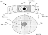
Figure 3A is a multi-camera display system comprising three screens to display images and/or videos obtained by a multi-camera endoscope tip section; -
Figure 3B is the multi-camera display system ofFigure 3A with a front view screen displaying a magnified image of an anomaly identified by a multi-focal front-pointing optical assembly; -
Figure 3C is the multi-camera display system ofFigure 3B with presentations on first and second side view screens disabled or darkened; -
Figure 4 is the endoscope tip section ofFigures 1A, 1B with a plurality of distance determining members in deployed configuration; -
Figure 5 is a flowchart illustrating a plurality of exemplary steps of a method of obtaining a magnified view of an area or object of interest within a body cavity, such as a colon, using a multi-focal front pointing optical assembly of a multi focal, multi-camera endoscope tip section; -
Figure 6A is a cross-section view of a multi-camera endoscope tip section having a multi-focal first side-pointing optical assembly, in accordance with an embodiment; -
Figure 6B is a cross-section view of a multi-camera endoscope tip section having a multi-focal first side-pointing composite optical assembly, in accordance with an embodiment; -
Figure 7A is a multi-camera display system comprising three screens to display images and/or videos obtained by a multi-camera endoscope tip section; -
Figure 7B is the multi-camera display system ofFigure 7A with a first-side view screen displaying a magnified image of an anomaly identified by a multi-focal first side-pointing optical assembly; -
Figure 7C is the multi-camera display system ofFigure 7B with presentations on front and second side view screens disabled or darkened; -
Figure 8A illustrates a multi-focal side pointing optical assembly within a body cavity and at a distance, from an object of interest, that does not match a working distance of the multi-focal side pointing optical assembly being used to obtain a magnified image of the object of interest; -
Figure 8B illustrates the multi-focal side pointing optical assembly ofFigure 8A within an inflated body cavity such that a distance of the multi-focal optical assemvbly, from the object of interest, approximately matches the working distance of the multi-focal side pointing optical assembly; -
Figure 8C illustrates the multi-focal side pointing optical assembly ofFigure 8A that deploys first and second distance determining members to position the multi-focal side pointing optical assembly at a distance, from the object of interest, approximately matching the working distance of the multi-focal side pointing optical assembly; -
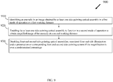
Figure 9 is a flowchart illustrating a plurality of exemplary steps of a method of obtaining a magnified view of an area or object of interest within a body cavity, such as a colon, using a multi-focal side pointing optical assembly of a multi focal, multi-camera endoscope tip section; -
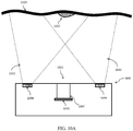
Figure 10A illustrates an endoscope tip section illuminating an anomaly, within a body cavity, at a first working distance; -
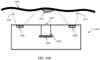
Figure 10B illustrates the endoscope tip section ofFigure 10A failiing to illuminate the anomaly at a second working distance; -
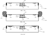
Figure 11A illustrates an endoscope tip section with an embodiment of a multi-focal optical assembly in a first mode of operation and a first type of light adjusting components retracted in a first mode of illumination; -
Figure 11B illustrates the endoscope tip section ofFigure 11A with the multi-focal optical assembly in a second mode of operation and the first type of light adjusting components deployed in a second mode of illumination; -
Figure 11C illustrates an endoscope tip section with a multi-focal optical assembly in the first mode of operation and first and second types of light adjusting components in the first mode of illumination; -
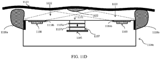
Figure 11D illustrates the endoscope tip section ofFigure 11C with the multi-focal optical assembly in the second mode of operation and at least one of the first and second types of light adjusting components in the second mode of illumination; -
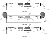
Figure 11E illustrates an endoscope tip section with another embodiment of a multi-focal optical assembly in a first mode of operation and the first type of light adjusting components retracted in the first mode of illumination; -
Figure 11F illustrates the endoscope tip section ofFigure 11E with the multi-focal optical assembly in the second mode of operation and the first type of light adjusting components deployed in the second mode of illumination; -
Figure 11G illustrates an endoscope tip section with a multi-focal optical assembly in the first mode of operation and first and second types of light adjusting components in the first mode of illumination; -
Figure 11H illustrates an endoscope tip section with an embodiment of a composite multi-focal optical assembly in the first mode of operation and the first type of light adjusting components retracted in the first mode of illumination; -
Figure 11I illustrates the endoscope tip section ofFigure 11H with the composite multi-focal optical assembly in the second mode of operation and the first type of light adjusting components deployed in the second mode of illumination; -
Figure 11J illustrates an endoscope tip section with a multi-focal composite optical assembly in the first mode of operation and first and second types of light adjusting components in the first mode of illumination; -
Figure 12 is a flowchart illustrating a plurality of exemplary steps of a method of obtaining a magnified view of an area or object of interest within a body cavity, such as a colon, using a multi focal, multi-camera endoscope tip section equipped with at least one of first and second types of light adjusting components; -
Figure 13A shows a graph illustrating a variation of relative illuminance with reference to a radiation angle for a light diffuser without application of an electrical field; and -
Figure 13B shows a graph illustrating a variation of relative illuminance with reference to a radiation angle for the light diffuser with application of an electric field. - The present specification is directed towards multiple embodiments. The following disclosure is provided in order to enable a person having ordinary skill in the art to practice the invention. Language used in this specification should not be interpreted as a general disavowal of any one specific embodiment or used to limit the claims beyond the meaning of the terms used therein. The general principles defined herein may be applied to other embodiments and applications without departing from the spirit and scope of the specification. Also, the terminology and phraseology used is for the purpose of describing exemplary embodiments and should not be considered limiting. Thus, the present specification is to be accorded the widest scope encompassing numerous alternatives, modifications and equivalents consistent with the principles and features disclosed. For purpose of clarity, details relating to technical material that is known in the technical fields related to the invention have not been described in detail so as not to unnecessarily obscure the present specification.
- In the description and claims of the application, each of the words "comprise" "include" and "have", and forms thereof, are not necessarily limited to members in a list with which the words may be associated.
- According to aspects and embodiments of the present invention, multi- focal (for example, dual focus) multi-camera endoscope systems are disclosed. The endoscope system, according to some embodiments, includes at least one multi-focal optical assembly comprising at least one image sensor and at least one lens assembly further comprising optical element(s) configured to shift from a first working distance to a second working distance, when triggered by a processor associated with the endoscope system, thereby to provide an increased magnification of an object of interest.
- As used herein in accordance with some embodiments, at least the lens assembly is part of a "camera" or "viewing element". In some embodiments, the term 'camera" is used to describe a lens assembly and its associated image sensor. The "camera" or "viewing element" with associated image sensor and associated circuit board form an "optical assembly". Further, the optical assembly typically is associated with at least one illuminator for illuminating the field of view. Thus, a multi-focal optical assembly includes a multi-focal viewing element with associated sensor, associated circuit board and is associated with at least one illuminator, in various embodiments. In various other embodiments, the multi-focal optical assembly is also associated with at least one of first and second types of light adjusting components configured to function in a first or a second mode of illumination. Throughout this specification, the terms "camera" and "viewing element" are used interchangeably.
- In some embodiments, a processing system is employed, wherein said processing system includes a processor in operation with local or remote memory and other electronic components known to persons of ordinary skill in the art.
- In some embodiments, portions of the present invention may be implemented as a plurality of software instructions executed by a data processor, for example, which is part of a general-purpose or custom computer. In some embodiments, the data processor or computer comprises volatile memory for storing instructions and/or data and/or a non-volatile storage, for example, a magnetic hard-disk and/or removable media, for storing instructions and/or data. In some embodiments, implementation includes a network connection. In some embodiments, implementation includes a user interface, generally comprising one or more input devices (e.g., allowing input of commands and/or parameters) and output devices (e.g., allowing reporting parameters of operation and results).
- Multi-camera endoscope systems also include a multi-screen display configured to display simultaneously a plurality of images captured by more than one optical assembly. However, zooming in and magnifying an image by a predetermined percentage, which may be over about 30% for example, while other images are displayed with a lower magnification on such multi-image display, may cause a loss of visual orientation and generally a visual fatigue and discomfort experience to the operator. Hence, according to aspects and embodiments of the present specification, the processor is configured to allow the operator to focus only on the magnified image of interest obtained from one optical assembly (which is a multi-focal optical assembly) by disabling other optical assemblies, the associated illumination and/or presentation of images obtained from the other optical assemblies or any combination thereof.
- Thus, in order to enable the operator to focus only on the magnified image of interest obtained from a multi-focal optical assembly, the processor is configured to enable any one or a combination of the following actions: a) switch off the other optical assemblies capturing the lower magnification images while one or more illuminators associated with the other optical assemblies continue to stay switched on and the screens displaying the lower magnification images also continue to remain switched on, b) switch off the one or more illuminators associated with the other optical assemblies while the other optical assemblies continue to capture and generate live images and/or video and the screens displaying the lower magnification images also continue to remain switched on, and/or c) switch off, darken or blacken the screens displaying the lower magnification images while the other optical assemblies continue to capture and generate live images and/or video and the one or more illuminators associated with the other optical assemblies also continue to stay switched on.
- Reference is now made to
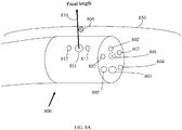
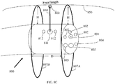
Figure 1 , which shows a cross section of a multi-focal, multi-camera endoscope tip section, according to certain embodiments.Endoscope tip section 100a includes a multi-focal front-pointingoptical assembly 101 positioned at a distal end of an endoscope, such as a colonoscope. Front-pointingoptical assembly 101 typically has a wide field of view of 170 degrees. Theendoscope tip section 100a includes a first side-pointingoptical assembly 102 and a second side pointingoptical assembly 103. The two side-pointingoptical assemblies optical assembly 101 are configured to provide an expanded field of view of about 330 degrees. In various embodiments, the first and second side-pointingoptical assemblies optical assemblies - While the multi-focal front-pointing
optical assembly 101 is able to detect objects of interest, such as polyps, visible in the front field of view, side-pointingoptical assemblies optical assembly 101, for example in inner side of folds of a colon. According to some embodiments, a focal length of the front-pointingoptical assembly 101 is on the order of 1.1 mm while that of the first and second side-pointingassemblies - The multi-focal front-pointing
optical assembly 101 includes a front-pointing viewing element or camera having a front-pointingimage sensor 105 such as Charge Coupled Device (CCD) or a Complementary Metal Oxide Semiconductor (CMOS) image sensor. The front-pointingimage sensor 105 has alens assembly 107 mounted on top of it for providing the necessary optics for receiving images. Thelens assembly 107 includes a plurality of lenses, static or movable, which provide a field of view of at least 90 degrees and up to essentially 180 degrees. - The front-pointing
image sensor 105 is mounted on anintegrated circuit board 106, which may be rigid or flexible. Theintegrated circuit board 106 supplies the front-pointingimage sensor 105 with necessary electrical power, and derives still images and/or video feeds captured by theimage sensor 105. Theintegrated circuit board 106 is connected to a set of electrical cables which are threaded through an electrical channel running through an elongated shaft of the endoscope. - One or more discrete
front illuminators 108 are placed next to thelens assembly 107, for illuminating its field of view. Optionally, discretefront illuminators 108 may be attached to the sameintegrated circuit board 106 on which front-pointingimage sensor 105 is mounted. Thus, in some embodiments, the multi-focal front-pointingoptical assembly 101, includes at least a front-pointing viewing element which compriseslens assembly 107 and front-pointingimage sensor 105, mounted on integratedcircuit board 106, and associated with at least oneilluminator 108. - In one embodiment, the illuminators are optionally discrete illuminators and include a light-emitting diode (LED). Thus, light is provided by light emitting diodes (LED) that illuminates the fields of view. According to some embodiments, white light LEDs are used. According to other embodiments, other colors of LEDs or any combination of LEDs may be used, including but not limited to red, green, blue, infrared, near infrared and ultraviolet or any other LED.
- The term "discrete", concerning discrete illuminator, refers to an illumination source, which generates light internally, in contrast to a non-discrete illuminator, which may be, for example, a fiber optic merely transmitting light generated remotely.
- In some embodiments, the light may be generated internally within the
endoscope tip section 100a, or generated remotely and transferred, for example, by a fiber optic. In some embodiments, two or more illuminators may be employed, wherein at least one may generate the light internally, and at least one may provide remotely generated light. - According to some embodiments of the present specification, the
lens assembly 107 includes twolenses optical assembly 101 and its associated components. - According to aspects and embodiments of the present specification, shifting from the first working distance to the second working distance allows for increased magnification and an improved image that can be generated by the
image sensor 105. Shifting to the second working distance allows using thelens 111 with improved modulation transfer function (MTF) and aberration qualities adapted to a shorter depth of field (DOF) compared to the longer DOF of the firstregular lens 109. For example, the first working distance and DOF of thefirst lens 109 is about 3 to 100 millimeters (mm) while the second working distance and DOF of thesecond lens 111 is about 2 to 5 mm or about 2 to 7 mm. The imaging performance provided by thesecond lens 111, adapted to shorter distances, is superior at these short distances compared to the imaging performance of the regularfirst lens 109, having typically 3 to 100 mm DOF, where a camera shutter is used to limit the field of view at short distances, thereby providing lower resolution and reduced light intensity. - In various alternate embodiments, the first working distance is about 6 to 70 mm, while the second working distance is about 2 to 4 mm.
- In accordance with aspects of the present specification, the
lens assembly 107 includes one or more actuation elements configured to control optical elements included in thelens assembly 107. The one or more actuation elements comprise a pneumatic engine, a piezoelectric element, an electric engine, solenoid, a Nitinol engine or any combination thereof. In a preferred embodiment, the actuation elements comprise at least one pneumatic engine. The optical elements comprise lenses (such aslenses 109, 111), mirrors, diffraction elements or any combination thereof. - In various embodiments, the actuation elements are triggered by the processor to push, move or pull
lens 109 out of theoptical path 110 and push, move or pulllens 111 onto theoptical path 110 such that theoptical path 110 that connects the line of sight fromimage sensor 105 to a target pass throughfirst lens 109 orsecond lens 111. - In accordance with various embodiments, the
endoscope tip section 100a includes a first side-pointingimage sensor 115, such as a CCD or a CMOS image sensor. The first side-pointingimage sensor 115 is mounted on anintegrated circuit board 116, which may be rigid or flexible. Theintegrated circuit board 116 supplies the first side-pointingimage sensor 115 with the necessary electrical power, and derives still images and/or video feeds captured by theimage sensor 115. Theintegrated circuit board 116 is connected to a set of electrical cables which are threaded through an electrical channel running through the elongated shaft of the endoscope. - The first side-pointing
image sensor 115 has alens assembly 117 mounted on top of it and providing the necessary optics for receiving images. Thelens assembly 117 includes a plurality of lenses, static or movable, which provide a field of view of at least 90 degrees and up to essentially 180 degrees. Thelens assembly 117 provides a working distance of about 5 to 100 millimeters, in one embodiment. In another embodiment, thelens assembly 117 provides a working distance of 2 to 5 millimeters. The first side-pointingimage sensor 115 and thelens assembly 117 are jointly referred to as a "first side-pointing viewing element". - One or more
discrete side illuminators 118 are placed next to thelens assembly 117, for illuminating its field of view. Optionally, discretefront illuminators 118 may be attached to the sameintegrated circuit board 116 on which the first side-pointingimage sensor 115 is mounted. - Thus, in some embodiments, side-pointing viewing element which comprises
lens assembly 117 and side-pointingimage sensor 115, mounted on integratedcircuit board 116, and associated with at least oneilluminator 118 forms a first side-pointing optical assembly. - In another configuration, the
integrated circuit boards image sensors - In some embodiments, the
endoscope tip section 100a includes a second side-pointingimage sensor 125, such as a CCD or a CMOS image sensor. Side-pointingimage sensor 125 is mounted on anintegrated circuit board 126, which may be rigid or flexible. Integratedcircuit board 126 supplies the side-pointingimage sensor 125 with the necessary electrical power, and derives still images and/or video feeds captured by theimage sensor 125. Theintegrated circuit board 126 is connected to a set of electrical cables which are threaded through an electrical channel running through the elongated shaft of the endoscope. - The side-pointing
image sensor 125 has alens assembly 127 mounted on top of it and providing the necessary optics for receiving images.Lens assembly 127 includes a plurality of lenses, static or movable, which provide a field of view of at least 90 degrees and up to essentially 180 degrees. Thelens assembly 127 provides a working distance of about 2 to 5 millimeters, in one embodiment. In another embodiment, thelens assembly 117 provides a working distance of 3 to 40 millimeters. The side-pointingimage sensor 125 and thelens assembly 127, are jointly referred to as a "second side-pointing viewing element". - One or more
discrete side illuminators 128 are placed next to thelens assembly 127, for illuminating its field of view. Optionally, discretefront illuminators 128 may be attached to the sameintegrated circuit board 126 on which side-pointingimage sensor 125 is mounted. - Thus, in some embodiments, the second side-pointing viewing element which comprises
lens assembly 127 and side-pointingimage sensor 125, mounted on integratedcircuit board 126, and associated with at least oneilluminator 128 forms a side-pointing optical assembly. - In another configuration, integrated
circuit boards image sensors - For simplicity of presentation,
Figure 1 only shows the viewing elements, associated components and illuminators (optical assemblies) of the multi focus, multiple viewing elementendoscope tip section 100a. It is understood thatendoscope tip section 100a may include one or more working channels, to enable insertion of multiple surgical tools simultaneously. Similarly,endoscope tip section 100a may include one or more fluid channels, such as for separately feeding at least one of a front fluid injector, a side fluid injector and/or a pathway fluid injector, as well as for separately providing suction through the pathway fluid injector.Endoscope tip section 100a may include one or more electrical cables threaded through an elongated shaft and/or a bending section for controlling the endoscope's cameras and illuminators. - Reference is now made to
Figure 2 , which shows a cross section of a multi focal, multi-cameraendoscope tip section 100b having two front pointing viewing elements and thus, optical assemblies, according to certain embodiments.Endoscope tip section 100b includes first and second front-pointing optical assemblies, 101A and 101B, also referred to together as a 'composite multi-focal optical assembly' which are positioned at a distal end of an endoscope, such as a colonoscope. Theendoscope tip section 100b includes a first side-pointingoptical assembly 102 and a second side pointingoptical assembly 103. In various embodiments, the first and second side-pointingoptical assemblies optical assemblies 101A, 101B and the first and second side-pointingoptical assemblies - Front-pointing optical assembly 101A includes a first front-pointing viewing element having a front-pointing
image sensor 105. Front-pointingimage sensor 105 has alens assembly 107 mounted on top of it and providing the necessary optics for receiving images.Lens assembly 107 includes a plurality of lenses, static or movable, which provide a field of view of at least 90 degrees and up to essentially 180 degrees.Lens assembly 107 provides a first working distance of about 5 to 100 millimeters. - Front-pointing
image sensor 105 is mounted on a firstintegrated circuit board 106. - Front-pointing
image sensor 105 andlens assembly 107, when coupled to integratedcircuit board 106, are jointly referred to as a "first front-pointing optical assembly". - Front-pointing
optical assembly 101B includes a second front-pointing viewing element having a front-pointingimage sensor 135. Front-pointingimage sensor 135 has alens assembly 137 mounted on top of it and providing the necessary optics for receiving images.Lens assembly 137 includes a plurality of lenses, static or movable, which provide a field of view of at least 90 degrees and up to essentially 180 degrees.Lens assembly 137 provides a second working distance of about 2 to 5 millimeters. - Front-pointing
image sensor 135 is mounted on a secondintegrated circuit board 136. - Front-pointing
image sensor 135 andlens assembly 137, when coupled to integratedcircuit board 136, are jointly referred to as a "second front-pointing optical assembly". - In accordance with an embodiment, the first front-pointing optical assembly 101A is a default endoscope front-pointing viewing element that includes
image sensor 105 andlens assembly 107 havinglens 109 providing the first working distance of 5 to 100 millimeters.Lens 109 is used during endoscopic procedures in order to navigateendoscope tip section 100b in patients' colons, for example, and is configured to identify anomalies or objects of interest, such as polyps, from relatively long distance and with relatively low magnification. One or morediscrete illuminators 108A are placed next tolens assembly 107, for illuminating its field of view. Optionally, discretefront illuminators 108A are attached to the sameintegrated circuit board 106 on which the front-pointingimage sensor 105 is mounted. - The second front-pointing
optical assembly 101B is an increased magnification camera that includesimage sensor 135 andlens assembly 137 havinglens 131 providing the second working distance of 3 to 6 millimeters.Lens 131 is configured to increase magnification of the identified object of interest. One or morediscrete illuminators 108B are placed next tolens assembly 137, for illuminating its field of view. Optionally, discretefront illuminators 108B are attached to the sameintegrated circuit board 136 on which front-pointingimage sensor 135 is mounted. - The
endoscope tip section 100b includes, in accordance with certain embodiments, a first side-pointingoptical assembly 102 comprising alens assembly 117 mounted on animage sensor 115 which is in turn mounted on anintegrated circuit board 116. The first side-pointingoptical assembly 102 also has one or more associateddiscrete illuminators 118. The endoscope tip section 100 also includes, in various embodiments, a second side-pointingoptical assembly 103 comprising alens assembly 127 mounted on animage sensor 125 which is in turn mounted on anintegrated circuit board 126. The second side-pointingoptical assembly 103 has one or more associateddiscrete illuminators 128. According to some embodiments, a focal length of the front-pointingoptical assemblies 101A, 101B is on or about the order of 1.1 mm while that of the first and second side-pointingassemblies - Reference is now made to
Figures 1 ,2 along withFigures 3A through 3C , which illustrate exemplary content displayable on a multi-focal, multi-cameraendoscope display system 300, according to certain embodiments. Theendoscope display system 300 includes afront view screen 301 used to display images captured by the front-pointingoptical assembly 101 ofFigure 1 or by the optical assembly 101A ofFigure 2 (depending upon whether theedoscope tip section pointing screen 303 used to display images captured by the first side pointingoptical assembly 102, shown inFigures 1 ,2 , and a second side-pointing screen 305 used to display images captured by the second side-pointingoptical assembly 103, shown inFigures 1 ,2 . Thus, it should be understood that if theendoscope tip section 100a ofFigure 1 is used, thefront view screen 301 will display the images captured by the front-pointingoptical assembly 101 while the side-pointingscreens optical assemblies Figure 1 . Alternately, if theendoscope tip section 100b ofFigure 2 is used, thefront view screen 301 will, by default, display the images captured by the front-pointing optical assembly 101A while the side-pointingscreens optical assemblies Figure 2 . - Thus, screens 301, 303 and 305 are configured to display simultaneously the field of views captured by multi-camera
endoscope tip section Figures 1 ,2 , providing expanded, 330 degrees of field of view, and allowing a clinician to navigate the endoscope tip section through the interrogated regions conveniently, to identify and treat objects of interest or anomalies. -
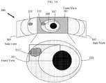
Figure 3A shows typical front and side view images of acolon 307, colon folds 309 and an object of interest that may be apolyp 311 shown onfront view screen 301.Polyp 311 may also be captured by the side-pointingviewing element 102 from a side viewing angle and is shown onside view screen 305 marked as polyp 311'. In operation, an operator advancesendoscope tip section 100a (or 100b ofFigure 2 ) within a body cavity, such as a colon, while viewing images (commonly a video feed) transmitted by theoptical assemblies Figure 1 (oroptical assemblies Figure 2 ). Upon discovery of an object of interest, such aspolyp 311, on a wall ofcolon 307 for example, the operator may further advance the multi-cameraendoscope tip section 100a (or 100b ofFigure 2 ) to the vicinity of thepolyp 311. After advancing theendoscope tip section 100a (or 100b ofFigure 2 ) to an "optimal distance" from the colon (or any body cavity) wall/polyp/any other point of interest, the operator may obtain a magnifiedobject image 320 using the secondworking distance lens 111 ofFigure 1 (when using theendoscope tip section 100a ofFigure 1 ) or the second front-pointingoptical assembly 101B (when using theendoscope tip section 100b ofFigure 2 ). - According to some embodiments, the "optimal distance" is determined by the operator, or is determined by a spacer / distance determining member in various embodiments. According to some embodiments, the "optimal distance" is, for example, 2-4 millimeters from the colon (or any body cavity) wall/polyp/any other point of interest. According to the magnified
image 311" of thepolyp 311, the operator may decide to insert a surgical tool through a working channel of the endoscope to remove, treat and/or extract a sample of thepolyp 311 or its entirety for biopsy. - Reference is now made to
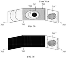
Figure 3B , which shows the magnifiedimage 311" on thefront view screen 301.Polyp 311 is shown magnified significantly, occupying a larger screen area of thefront view screen 301. Magnification of the side view screens 303, 305 is not changed and polyp 311' is still shown on theside view screen 305 with default magnification. However, zooming in and magnifying thepolyp 311, by about 30% or more for example, on thefront view screen 301, while the sideview screen images - Reference is now made to
Figure 3C , which shows a magnifiedimage 311" on thefront view screen 301 and disabled,blackened and/or darkened side view screens 303 and 305.Polyp 311 is shown magnified significantly, asimage 311", and occupying a large screen area of thefront view screen 301 while the two side view screens 303 and 305 are disabled, darkened and/or blackened. Disabling, darkening and/or blackening the side view screens 303 and 305 allows the operator to interrogate the magnifiedpolyp image 311" with no visual disturbances or distractions. - While zooming in and magnifying an image of an object of interest, such as that of the polyp 311, using increased magnification lens 111 of
Figure 1 (when using the endoscope tip section 100a ofFigure 1 ) or the second front-pointing optical assembly 101B (when using the endoscope tip section 100b ofFigure 2 ), according to aspects and embodiments of the present specification, a processor is configured to enable any one or a combination of the following: a) disable the side pointing optical assemblies (102 and 103 ofFigures 1 ,2 ) such as by cutting off or reducing their power supply, while the side pointing illuminators (118, 128 - associated with the side pointing optical assemblies 102 and 103 ofFigure 1 ,2 ) continue to stay switched on and the two side pointing screens or monitors (303 and 305) also continue to be switched on, b) switch off or reduce the illumination intensity of the side pointing illuminators (118, 128 ofFigures 1 ,2 ) associated with the side pointing optical assemblies while the side pointing optical assemblies continue to capture live images and/or video streams and the two side view screens (303 and 305) also continue to be switched on, and/or c) terminate the presentation of the side pointing screens or monitors (303 and 305) obtained from the side pointing optical assemblies on the two side pointing screens (303 and 305) by switching off, darkening or blackening of the two side pointing screens while the side pointing optical assemblies (102, 103 ofFigures 1 ,2 ) continue to capture live images and/or video streams and the illuminators (118, 128 ofFigures 1 ,2 ) associated with the side pointing optical assemblies also continue to remain switched on. - Also in one embodiment, the disabling of the side pointing optical assemblies, associated illuminators and/or switching off, blackening or darkening of the two side pointing screens is automatically enabled by the processor when the increased
magnification lens 111 ofFigure 1 (when using theendoscope tip section 100a ofFigure 1 ) or the second front-pointingoptical assembly 101B (when using theendoscope tip section 100b ofFigure 2 ) is enabled for magnified viewing of the object of interest. In another embodiment, the operator manually enables, such as by manipulating one or more switches on the handle of the endoscope, any one or combination of disabling of the side pointing optical assemblies, associated illuminators and/or switching off, blackening or darkening of the two side pointing screens, when the increasedmagnification lens 111 ofFigure 1 (when using theendoscope tip section 100a ofFigure 1 ) or the second front-pointingoptical assembly 101B (when using theendoscope tip section 100b ofFigure 2 ) is enabled for magnified viewing of the object of interest. - With reference to
Figure 2 , according to aspects and embodiments of the present specification, the processor is configured to turn on, for zooming in, front pointingoptical assembly 101B, to turn off front pointing optical assembly 101A, to turn off the illumination associated with the front pointing optical assembly 101A (that is, turning off the one ormore illuminators 108A for example) and to display the magnified image captured by the front pointingoptical assembly 101B replacing the image captured by the front pointing optical assembly 101A on thefront view screen 301. The processor is further configured to enable any one or a combination of the following: a) turn off, for zooming in, the side pointingoptical assemblies illuminators side pointing screens side pointing illuminators optical assemblies optical assemblies side pointing screens side pointing screens optical assemblies side pointing illuminators - Also in one embodiment, the disabling of the side pointing optical assemblies, associated illuminators and/or switching off, blackening or darkening of the two side pointing screens is automatically enabled by the processor when when using the second front-pointing
optical assembly 101B is enabled for magnified viewing of the object of interest. In another embodiment, the operator manually enables, such as by manipulating one or more switches on the handle of the endoscope, any one or combination of disabling of the side pointing optical assemblies, associated illuminators and/or switching off, blackening or darkening of the two side pointing screens, when the second front-pointingoptical assembly 101B is enabled for magnified viewing of the object of interest. - Reference is now made to
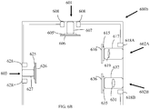
Figure 4 , which shows a perspective view of a multi-focal, multi-cameraendoscope tip section 400 comprising one or more distance determining members or spacers. Theendoscope tip section 400 includes a front-pointingoptical assembly 401, associated with one or more front-pointingilluminators 402, a workingchannel 403, afluid injection channel 404, afluid injection channel 405 for cleaning theoptical assembly 401 andilluminators 402, a side-pointingoptical assembly 411 which is associated with one or more side-pointingilluminators 412. - In accordance with an embodiment, the
endoscope tip section 400 includes one or more, preferably three or more, distance determining members orspacers optical assembly 401 and the inner wall of the colon. In various embodiments, the three or moredistance determining members distal end 420 of thetip section 400 or retractably pulled out of theendoscope tip section 400, when needed. - In accordance with various embodiments, a protruding length of the three or more
distance determining members distal end 420, approximately matches the second working distance of the magnifyingsecond lens 111 ofFigure 1 or that of the second front-pointingoptical assembly 101B ofFigure 2 . Thus, in various embodiments, the protruding length of the three or more distance determining members orspacers spacers spacers optical assembly 401 is not distorted by thespacers distance determining members distal end 420, the protruding lengh of thedistance determining members distance determining members - According to some embodiments, the distance determining members are configured to provide distance determination or spacing of approximately 4 mm. According to some embodiments, the distance determining members are configured to provide distance determination of more than 5 mm. According to other embodiments, the distance determining members are configured to controllably provide distance determination for more than one distance ranging between 3 mm and 12mm. According to still other embodiments, the distance determining members are configured to controllably provide distance determining for more than one distance ranging between 4 mm and 6 mm. According to various embodiments, the distance determining members are configured to provide dynamic distance determination according to the working distance.
-
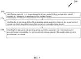
Figure 5 is a flowchart illustrating a plurality of exemplary steps of amethod 500 of obtaining a magnified view of an area or object of interest within a body cavity, such as a colon, using a multi focal, multi-camera endoscope tip section of an endoscope, such as a colonoscope. A processor, associated with the endoscope, is configured to implement themethod 500. Referring now toFigures 1 ,2 and5 , at step 510 a multi focal, multi-camera endoscope tip section, such as thetip section optical assembly 101 of thetip section 100a or the first front-pointing optical assembly 101A of thetip section 100b) to identify an anomaly, area or object of interest - such as a polyp. During the first mode of operation the at least one multi-focal front-pointing optical assembly obtains images and/or videos of the colon at a first working distance. The at least one multi-focal front-pointing optical assembly is enabled to function at the first working distance using afirst lens 109 or a first front-pointing optical assembly 101A (while the second front-pointingoptical assembly 101B is disabled) depending upon whether theendoscope tip section - The images and/or videos obtained from the at least one multi-focal front-pointing optical assembly, in the first mode of operation, are displayed on a front view screen along with an identified anomaly, while the images and/or videos obtained from a first and a second side-pointing optical assemblies are displayed respectively on corresponding first and second side-pointing screens. It should be appreciated that the identified anomaly visible on the front view screen, as captured by the at least one multi-focal front-pointing optical assembly, may also be simultaneously displayed on at least one of the first or second side-pointing screens as captured in an overlapping field of view of at least one of the first or second side-pointing optical assemblies. In various embodiments, during the first mode of operation a magnification of 100x -6x of the captured image of the anomaly is enabled for the first working distance.
- At
step 520, the processor enables the at least one multi-focal front-pointing optical assembly to function in a second mode of operation in order to obtain and display a magnified image, comprising the identified anomaly, on the front view screen. During the second mode of operation the at least one multi-focal front-pointing optical assembly obtains the magnified image at a second working distance. The at least one multi-focal front-pointing optical assembly is enabled to function at the second working distance by switching to using asecond lens 111 or by activating a second front-pointingoptical assembly 101B (while simultaneously disabling the first front-pointing optical assembly 101A) depending upon whether theendoscope tip section - In accordance with an embodiment, a distance between the at least one multi-focal front-pointing optical assembly and the identified anomaly or object of interest is maintained by pulling or deploying one or more distance determining members, such as the
members Figure 4 , out of a distal end of the endoscope tip section and advancing the tip section until the one or more distance determining members contact the anomaly or the inner wall of the colon thereby maintaining the distance to approximately the second working distance. In this embodiment, a length of the distance determining members can be varied by retracting or deploying them partially or fully. In other embodiments, the distance determining members are affixed to the distal end and are of a fixed length approximately matching the second working distance. Operationally, this structure has the benefit of ensuring a minimum distance is kept between the endoscope camera(s) and tissue being observed. - At
step 530, when the magnification of the magnified image on the front view screen is over a predetermined percentage, the processor enables any one or a combination of the following, : a) turns off or disables the first and second side-pointing optical assemblies while the illuminators associated with the first and second side-pointing optical assemblies stay switched on and the first and second side pointing screens also continue to be switched on, b) switch off the side illuminators associated with the first and second side-pointing optical assemblies while the first and second side-pointing optical assemblies continue to capture and generate live images and/or video streams and the first and second side pointing screens also continue to be switched on, and/or c) switch off, blacken or darken presentation of the images and/or videos on the first and second side-pointing screens while the first and second side-pointing optical assemblies continue to capture and generate live images and/or video streams and the illuminators associated with the first and second side-pointing optical assemblies also continue to stay switched on. ,. In some embodiments, the predetermined magnification percentage is about 30% or more. - If required, a surgical tool may be inserted through a working channel of the endoscope in order to remove, treat and/or extract a sample of the anomaly or object of interest or its entirety for biopsy, while viewing the magnified image.
- In accordance with an embodiment, actuating a button or switch on a handle of the endoscope prompts the processor to switch the endoscope tip section from the first mode of operation to the second mode of operation.
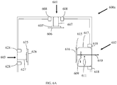
- Reference is now made to
Figure 6A , which shows a cross-section of a multi-focal, multi-camera endoscope tip section, according to certain embodiments.Endoscope tip section 600a includes a front-pointingoptical assembly 601 that is positioned at a distal end of an endoscope, such as a colonoscope. The front-pointingoptical assembly 601 typically has a wide field of view of 170 degrees. Theendoscope tip section 600a includes a first multi-focal side-pointingoptical assembly 602 and a second side-pointingoptical assembly 603. The two side-pointingoptical assemblies optical assembly 601 are configured to provide an expanded field of view of about 330 degrees. In various embodiments, the first and second side-pointingoptical assemblies optical assemblies - While the front-pointing
optical assembly 601 is able to detect objects of interest, such as polyps, visible in the front field of view, side-pointingoptical assemblies optical assembly 601, for example within the inner sides of the folds of a colon. According to some embodiments, a focal length of the front-pointingoptical assembly 601 is on the order of 1.1 mm while that of the first and second side-pointingassemblies - The front-pointing
optical assembly 601 includes a front-pointing viewing element or camera having a front-pointingimage sensor 605 such as Charge Coupled Device (CCD) or a Complementary Metal Oxide Semiconductor (CMOS) image sensor. The front-pointingimage sensor 605 has alens assembly 607 mounted on top of it to provide the necessary optics for receiving images. Thelens assembly 607 includes a plurality of lenses, static or movable, which provide a field of view of at least 90 degrees and up to essentially 180 degrees. - The front-pointing
image sensor 605 is mounted on anintegrated circuit board 106, which may be rigid or flexible. Theintegrated circuit board 606 supplies the front-pointingimage sensor 605 with the necessary electrical power, and derives still images and/or video feeds captured by theimage sensor 605. Theintegrated circuit board 606 is connected to a set of electrical cables which are threaded through an electrical channel running through an elongated shaft of the endoscope. - One or more discrete
front illuminators 608 are placed next to thelens assembly 607, for illuminating its field of view. Optionally, discretefront illuminators 608 may be attached to the sameintegrated circuit board 606 on which the front-pointingimage sensor 605 is mounted. Thus, in some embodiments, the front-pointingoptical assembly 601 includes at least a front pointing-viewing element which compriseslens assembly 107 and front-pointingimage sensor 105, mounted on integratedcircuit board 106, and associated with at least oneilluminator 608. - In one embodiment, the illuminators are optionally discrete illuminators and include a light-emitting diode (LED). Thus, light is provided by light emitting diodes (LED) that illuminates the fields of view. According to some embodiments, white light LEDs are used. According to other embodiments, other colors of LEDs or any combination of LEDs may be used, including but not limited to red, green, blue, infrared, near infrared and ultraviolet or any other LED.
- In some embodiments, light may be generated internally within the
endoscope tip section 600a, or generated remotely and transferred, for example, by a fiber optic. In some embodiments, two or more illuminators may be employed, wherein at least one may generate the light internally, and at least one may provide remotely generated light. - In accordance with various embodiments, the
endoscope tip section 600a includes a first side-pointingimage sensor 615, such as CCD or a CMOS image sensor. The first side-pointingimage sensor 615 is mounted on anintegrated circuit board 616, which may be rigid or flexible. Theintegrated circuit board 616 supplies the first side-pointingimage sensor 615 with the necessary electrical power, and derives still images and/or video feeds captured by theimage sensor 615. Theintegrated circuit board 616 is connected to a set of electrical cables which are threaded through an electrical channel running through the elongated shaft of the endoscope. - The first side-pointing
image sensor 615 has alens assembly 617 mounted on top of it for providing the necessary optics for receiving images. Thelens assembly 617 includes a plurality of lenses, static or movable, which provide a field of view of at least 90 degrees and up to essentially 180 degrees. Thelens assembly 617 provides a working distance of about 2 to 40 millimeters, in one embodiment. In another embodiment, thelens assembly 617 provides a working distance of 2 to 6 millimeters. The first side-pointingimage sensor 615 and thelens assembly 617, are jointly referred to as a "first side-pointing viewing element". - One or more
discrete side illuminators 618 are placed next to thelens assembly 617, for illuminating its field of view. Optionally, discretefront illuminators 618 may be attached to the sameintegrated circuit board 616 on which the first side-pointingimage sensor 615 is mounted. - Thus, in some embodiments, side-pointing viewing element which comprises
lens assembly 617 and first side-pointingimage sensor 615, mounted on integratedcircuit board 616, and associated with at least oneilluminator 618 forms a first side-pointing optical assembly. - In another configuration, the
integrated circuit boards image sensors - According to some embodiments of the present specification, the
lens assembly 617 includes twolenses optical assembly 602 and associated components. - According to aspects and embodiments of the present specification, shifting from the first working distance to the second working distance allows for increased magnification and an improved image that can be generated by the
image sensor 615. Shifting to the second working distance allows using thelens 611 with improved modulation transfer function (MTF) and aberration qualities adapted to a shorter depth of field (DOF) compared to the longer DOF of the firstregular lens 609. For example, in one embodiment, thelens assembly 617 provides a first working distance of about 20 millimeters provided by thelens 609 and a second working distance of about 5 millimeters provided by thelens 611. Alternatively, in another embodiment, thelens assembly 617 provides a first working distance of about 10 millimeters provided by thelens 609 and a second working distance of about 2 millimeters provided by thelens 611. It should be appreciated that thelens assembly 617 may provide other lenses with other working distances, typically in the range of 2 to 40 millimeters, and such lenses are within the scope of the present specification. - In accordance with an aspect of the present specification, the
lens assembly 617 includes one or more actuation elements configured to control optical elements included in thelens assembly 617. The one or more actuation elements comprise a piezoelectric element, an electric engine, solenoid, a Nitinol engine or any combination thereof. In a preferred embodiment, the actuation elements comprise at least one pneumatic engine. The optical elements comprise lenses (such aslenses 609, 611), mirrors, diffraction elements or any combination thereof. - In various embodiments, the actuation elements are triggered by the processor to push, move or pull the
lens 609 out of theoptical path 610 and push, move or pull thelens 611 onto theoptical path 610 such that the optical path that connects the line of sight from theimage sensor 615 to an anomaly or object of interest passes through thefirst lens 609 or thesecond lens 611. In some embodiments, theendoscope tip section 600a includes a second side-pointingimage sensor 625, such as a CCD or a CMOS image sensor. The second side-pointingimage sensor 625 is mounted on anintegrated circuit board 626, which may be rigid or flexible. Theintegrated circuit board 626 supplies the second side-pointingimage sensor 625 with the necessary electrical power, and derives still images and/or video feeds captured by theimage sensor 625. Theintegrated circuit board 626 is connected to a set of electrical cables which are threaded through an electrical channel running through the elongated shaft of the endoscope. - The second side-pointing
image sensor 625 has alens assembly 627 mounted on top of it for providing the necessary optics for receiving images. Thelens assembly 627 includes a plurality of lenses, static or movable, which provide a field of view of at least 90 degrees and up to essentially 180 degrees. Thelens assembly 627 provides a working distance of about 2 to 6 millimeters, in one embodiment. In another embodiment, thelens assembly 627 provides a working distance of 2 to 40 millimeters. The second side-pointingimage sensor 625 and thelens assembly 627 are jointly referred to as a " second side-pointing viewing element". - One or more
discrete side illuminators 628 are placed next to thelens assembly 627, for illuminating its field of view. Optionally, the discretefront illuminators 628 may be attached to the sameintegrated circuit board 626 on which the side-pointingimage sensor 625 is mounted. - Thus, in some embodiments, the second side pointing-viewing element which comprises
lens assembly 627 and side-pointingimage sensor 625, mounted on integratedcircuit board 626, and associated with at least oneilluminator 628 forms a second side-pointing optical assembly. - In another configuration, the
integrated circuit boards image sensors - In certain embodiments, the
lens assembly 627 may also be a multi-focal (dual focus, for example) lens assembly similar to thelens assembly 617 described hereinabove that includes two lenses (such as thefirst lens 609 and the second lens 611) that may also be switched dynamically by the processor in order to shift from a first working distance to a second working distance to increase magnification of an image of an object of interest captured by the second side-pointingoptical assembly 603. - Optionally and additionally, one or more lens assemblies, described herein above, may further include an autofocus zoom system, an optical zoom system and/or a digital zoom system.
- For simplicity of presentation,
Figure 6A only shows the viewing elements, associated components, and illuminators (together, optical assemblies) of the multi-focal, multi viewing elementendoscope tip section 600a. It is understood thatendoscope tip section 600a may include one or more working channels that enable the insertion of multiple surgical tools simultaneously. Similarly,endoscope tip section 600a may include one or more fluid channels, such as for separately feeding at least one of a front fluid injector, a side fluid injector and/or a pathway fluid injector, as well as for separately providing suction through the pathway fluid injector. Theendoscope tip section 600a may also include one or more electrical cables threaded through an elongated shaft and/or a bending section for controlling the endoscope's cameras and illuminators. - Reference is now made to
Figure 6B , which shows a cross section of multi-focal, multi-cameraendoscope tip section 600b comprising two first side-pointing viewing elements, and thus optical assemblies, according to certain embodiments. Theendoscope tip section 600b includes two first side-pointingoptical assemblies endoscope tip section 600b may also include an additional side-pointingoptical assembly 603 pointing at an opposing second side relative to the first side. - The first side-pointing
first viewing element 602A includes a side-pointingimage sensor 615 having alens assembly 617 mounted on top of it for providing the necessary optics for receiving images. The side-pointingimage sensor 615 is mounted on anintegrated circuit board 616. Thelens assembly 617 includes a plurality of lenses, static or movable, which provide a field of view of at least 90 degrees and up to essentially 180 degrees. Thelens assembly 617 provides a working distance of about of about 4 to 40 millimeters, in one embodiment. In another embodiment, thelens assembly 617 provides a working distance of 2 to 5 millimeters. The side-pointingimage sensor 615 and the lens assembly 617when coupled to the integratedcircuit board 616 and associated with at least oneilluminator 618A, are jointly referred to as a "first side-pointing first optical assembly". - The first side-pointing
second viewing element 602B includes a side-pointingimage sensor 635 having alens assembly 637 mounted on top of it and providing the necessary optics for receiving images. The side-pointingimage sensor 635 is mounted on anintegrated circuit board 636. Thelens assembly 637 includes a plurality of lenses, static or movable, which provide a field of view of at least 90 degrees and up to essentially 180 degrees. Thelens assembly 637 provides a working distance of about 2 to 5 millimeters, in one embodiment. In another embodiment, thelens assembly 637 provides a working distance of 3 to 6 millimeters. The side-pointingimage sensor 635 and thelens assembly 637, when coupled to the integratedcircuit board 636 and associated with at least oneilluminator 618B, are jointly referred to as a "first side-pointing second optical assembly". - In accordance with an embodiment the first side-pointing
first viewing element 602A is a default viewing element for the first side that includes theimage sensor 615 and thelens assembly 617 having alens 619 providing a first working distance of 2 to 40 millimeters. Thelens 619 is used during endoscopic procedures in order to navigate theendoscope tip section 600b in patients' colons, for example, and is configured to identify objects of interest from relatively long distance and with relatively low magnification. One or morediscrete illuminators 618A are placed next to thelens assembly 617, for illuminating its field of view. Optionally,discrete side illuminators 618A are attached to the sameintegrated circuit board 616 on which the side-pointingimage sensor 615 is mounted. - The first side-pointing
second viewing element 602B is an increased magnification camera that includesimage sensor 635 andlens assembly 637 havinglens 631 for providing a second working distance of 2 to 6 millimeters. Thelens 631 is configured to increase magnification of the identified object of interest. One or morediscrete illuminators 618B are placed next to thelens assembly 637, for illuminating its field of view. Optionally,discrete side illuminators 618B are attached to the sameintegrated circuit board 636 on which the side-pointingimage sensor 635 is mounted. - The
endoscope tip section 600b includes, in accordance with certain embodiments, a front-pointingoptical assembly 601 comprising alens assembly 607 mounted on animage sensor 605 which is in turn mounted on anintegrated circuit board 606. The front-pointingoptical assembly 601 also has one or more associateddiscrete illuminators 608. Theendoscope tip section 600b also includes, in various embodiments, a second side-pointingoptical assembly 603 comprising alens assembly 627 mounted on animage sensor 625 which is in turn mounted on anintegrated circuit board 626. The second side-pointingoptical assembly 603 has one or more associateddiscrete illuminators 628. In various embodiments, the first and second side-pointingoptical assemblies optical assemblies optical assemblies - Optionally, in additional embodiments, the
optical assembly 603 may also include two second side-pointing optical assemblies similar to the first side-pointing firstoptical assembly 602A and the first side-pointing secondoptical assembly 602B described herein above. According to some embodiments, a focal length of the front-pointingoptical assembly 601 is on the order of 1.1 mm while that of the first and second side-pointing assemblies 602 (602A, 602B), 603 is on the order of 1.0 mm. - Reference is now made to
Figures 6A ,6B along withFigures 7A through 7C , which illustrate exemplary content displayable on a multi-focal, multi-cameraendoscope display system 700, according to certain embodiments. Theendoscope display system 700 comprises afront view screen 701 used to display images captured by the front-pointingoptical assembly 601 shown inFigures 6A ,6B , a first side-view screen 703 used to display images captured by the first side-pointingoptical assembly 602 ofFigure 6A or the first side-pointing firstoptical assembly 602A ofFigure 6B (depending upon whether theendoscope tip section view screen 705 used to display images captured by the second side-pointingoptical assembly 703, shown inFigures 6A ,6B . Thus, it should be understood that if theendoscope tip section 600a ofFigure 6A is used, thefront view screen 701 will display the images captured by the front-pointingoptical assembly 601 while the side-pointingscreens optical assemblies Figure 6A . Alternately, if theendoscope tip section 600b ofFigure 6B is used, thefront view screen 701 will display the images captured by the front-pointingoptical assembly 601 while the side-pointingscreens optical assembly 602A, by default, and the second side-pointingoptical assemblies 603 shown inFigure 6B . - Thus, the
screens endoscope tip section Figures 6A ,6B , providing an expanded, 330 degrees field of view, and allowing a clinician to navigate the endoscope tip section through the interrogated regions conveniently, to identify and treat objects of interest or anomalies. -
Figure 7A , shows typical front and side view images of acolon 707, colon folds 709 and an object of interest, such as apolyp 711, captured by the first side-pointingoptical assembly 602 or the first side-pointing firstoptical assembly 602A (depending upon whether theendoscope tip section side view screen 703. An exploded view of the firstside view screen 703, displaying a magnifiedimage 720 is shown comprising a magnified image of thepolyp 311 and marked therein as 711". - During an endoscopic procedure, when the
endoscope tip section endoscope tip section 600a (or 600b) while viewing images (commonly a video feed) transmitted by theoptical assemblies Figure 6A (or theoptical assemblies Figure 6B ). Upon identification or discovery of thepolyp 711, on the wall of the colon, the operator may move or advance theendoscope tip section 600a (or theendoscope tip section 600b) to the vicinity of thepolyp 711, and may magnify the polyp image using the first side-pointingoptical assembly 602 with the secondworking distance lens 611, shown inFigure 6A , in accordance with an embodiment. In another embodiment, the operator may magnify the polyp image using the first side-pointing secondoptical assembly 602B comprising the secondworking distance lens 631, shown inFigure 6B . Depending upon the status of thepolyp 711 as represented by the magnifiedimage 711", the operator may decide to insert a surgical tool through a working channel of the endoscope to remove, treat and/or extract a sample of thepolyp 711 or its entirety for biopsy. - Reference is now made to
Figure 7B , which shows the magnifiedimage 311" on theside view screen 703. Thepolyp 311 is shown magnified significantly occupying a large part of theside view screen 703. However, the images of thecolon 707 and the colon folds 709 are shown with default magnification on thefront view screen 701, for example. However, zooming in and magnifying thepolyp 311, by about 30% or more, for example, on the firstside view screen 703, while the images on thefront view screen 701 and the secondside view screen 705 are displayed with a default magnification, may cause a loss of visual orientation and generally visual fatigue and discomfort, which may endanger successful interrogation, treatment and/or removal of the polyp by the operator. - Reference is now made to
Figure 7C , which shows a magnified image on the firstside view screen 703 and darkened, blackened or disabledfront view screen 701 and secondside view screen 705. Thepolyp 311 is shown magnified significantly and occupying a large part of the firstside view screen 703 while the other twoscreens front view screen 701 and the secondside view screen 705 allow the operator to interrogate the magnifiedpolyp image 311" with no visual disturbances or distractions. - According to aspects and embodiments of the present specification, a processor is configured to perform the following actions, in any sequence,:
- Switch off the front pointing
optical assembly 601, switch off the associatedilluminators 608 and/or switch off, blacken or darken presentation of thefront view screen 701, - Switch off the second side-pointing
optical assembly 603, switch off the associatedilluminators 628 and/or switch off, blacken or darken presentation of the secondside view screen 705, - Switch the first side
optical assembly 602 from the first working distance to the second working distance by moving thefirst lens 609 out and instead moving thesecond lens 611 into theoptical path 610, for zooming in, - if theendoscope tip section 600a is being used. Alternatively, switch off, deactivate or disable, such as by cutting electrical power supply, the first side-pointing firstoptical assembly 602A (having the first working distance) and switch on, activate or enable, such as by allowing electrical power supply, the first side-pointing secondoptical assembly 602B (having the second working distance), for zooming in, - if theendoscope tip section 600b is being used. - This enables, the
front view screen 701 and the secondside view screen 705 to be disabled, blackened or darkened while the firstside view screen 703 display the magnifiedpolyp image 711" replacing the earlier non-magnified image of thepolyp 311. - Reference is now made to
Figure 8A , which shows a perspective view of a multi-focal, multi-camera endoscope tip section, an inner wall of a body cavity and an object of interest, according to certain embodiments. Endoscope tip section 800 (which may be thetip section Figures 6A ,6B ) includes front-pointing viewing element orcamera 801, one or more front-pointingilluminators 802, a workingchannel 803, afluid injection channel 804, afluid injection channel 805 for cleaningcamera 801 andilluminators 802, a multi-focal side-pointingviewing element 811 and one or more side-pointingilluminators 812. Theendoscope tip section 800, in various alternate embodiments, also optionally includes another side-pointing viewing element and associated one or more side-pointing illuminators positioned on the other side opposing the side of themulti-focal viewing element 811. - According to some embodiments, the term 'inner wall of a body cavity', includes, for example, an inner wall of a colon or intestine. The multi-camera
endoscope tip section 800 is illustrated in the vicinity of the inner wall of thebody cavity 850 that may be a colon wall for example, having an anomaly or object ofinterest 860 that may require further interrogation. For further interrogation, operation of the multi-focal side-pointingviewing element 811 is shifted from a first working distance, such as that provided by thelens 609 ofFigure 6A or that provided by the first side-pointing firstoptical assembly 602B ofFigure 6B , to an increased magnification or second working distance, such as that provided by thelens 611 shown onFigure 6A , for example, or that provided by the first side-pointing secondoptical assembly 602B ofFigure 6B . In accordance with an aspect, the object ofinterest 860 may be too close to the multi-focal side pointingviewing element 811 as shown by thearrow 810 that illustrates the increased magnification or second working distance. As illustrated in the figure, since the distance to theobject 860 does not match the working distance of the increasedmagnification lens 611 or the working distance provided by the first side-pointing secondoptical assembly 602B, zooming in and shifting to the increased magnification working distance may generate a blurry image of theobject 860 on theside view screen 703, shown inFigure 7A . - Reference is now made to
Figure 8B , which shows a perspective view of the multi-focal, multi-cameraendoscope tip section 800 with an inflated colon, according to certain embodiments. In various embodiments, the inner wall of thebody cavity 850 is pushed away from theendoscope tip section 800, thereby increasing the distance of the multi-focal side-pointingviewing element 811 to the inner wall, such that the working distance, illustrated by thearrow 810, approximately matches the distance from the side- pointingviewing element 811 to the object ofinterest 860. In one embodiment, the distance of the multi-focal side-pointingviewing element 811 to the inner wall of thebody cavity 850 is increased or adjusted, for example, by injecting gas into the colon through thefluid injection channel 804. - Reference is now made to
Figure 8C , which shows a perspective view of the multi-focal, multi-cameraendoscope tip section 800 comprising one or more, preferably three or more, distance determining members configured to contact the inner wall of the body cavity, according to certain embodiments. In accordance with an aspect of the present specification, distance determining members or spacers, such as thespacers tip section 800 and are configured to maintain a distance between the multi-focal side pointingviewing element 811 to the inner wall of thebody cavity 850. While in the present embodiment, twodistance determining members Figure 8C , a preferred embodiment comprises three or more such distance determining members. In alternate embodiments, one or more distance determining members or spacers are utilized. The first and seconddistance determining members viewing element 811 to theobject 860 that matches the increased magnification or second working distance, such as that provided by thelens 611 shown onFigure 6A , for example, or that provided by the first side-pointing secondoptical assembly 602B ofFigure 6B . Thus, thedistance determining members tip section 800, to enable a stable magnified image captured by the multi-focal side-pointingviewing element 811 for display on the side view screen 703 (shown inFigure 7C ). - In various embodiments, the one or more
distance determining members tip section 800 or pulled radially and outwardly from thetip section 800 when triggered or actuated, such as by pushing a button or switch on a handle of an endoscope comprising theendoscope tip section 800, in one embodiment, or by configuring a processor, associated with the endoscope, to automatically deploy the rings when the multi-focal side-pointingviewing element 811 is enabled to obtain magnified images at the second working distance such as that provided by thelens 611 shown onFigure 6A , for example, or that provided by the first side-pointing secondoptical assembly 602B ofFigure 6B . In alternate embodiments, the one or moredistance determining members protrusions Figure 4 . - In various embodiments, the radially protruding height 'H' of the distance determining members or
spacers spacers viewing element 811 is not distorted by thespacers distance determining members -
Figure 9 is a flowchart illustrating a plurality of exemplary steps of amethod 900 of obtaining a magnified view of an area or object of interest within a body cavity, such as a colon, using a multi focal, multi-camera endoscope tip section of an endoscope, such as a colonoscope. A processor, associated with the endoscope, is configured to implement themethod 900. Referring now toFigures 6A ,6B and9 , at step 910 a multi focal, multi-camera endoscope tip section, such as thetip section optical assembly 602 of thetip section 600a or the first side-pointing firstoptical assembly 602A of thetip section 600b) to identify an anomaly, area or object of interest - such as a polyp. During the first mode of operation the at least one multi-focal side-pointing optical assembly obtains images and/or videos of the colon at a first working distance. The at least one multi-focal side-pointing optical assembly is enabled to function at the first working distance using afirst lens 609 or a first side-pointing firstoptical assembly 602A (while the first side-pointing secondoptical assembly 602B is disabled) depending upon whether theendoscope tip section - The images and/or videos obtained from the at least one multi-focal side-pointing optical assembly, in the first mode of operation, are displayed on a corresponding first side view screen along with an identified anomaly, while the images and/or videos obtained from a front and a second side-pointing optical assemblies are displayed respectively on corresponding front and second side-pointing screens. It should be appreciated that the identified anomaly visible on the first side view screen, as captured by the at least one multi-focal side-pointing optical assembly, may also be simultaneously displayed on the front viewing screen as also captured in an overlapping field of view of the front-pointing optical assembly. In various embodiments, during the first mode of operation a magnification of 100x to 6x of the captured image of the anomaly is enabled for the first working distance.
- At
step 520, the processor enables the at least one multi-focal side-pointing optical assembly to function in a second mode of operation in order to obtain and display a magnified image, comprising the identified anomaly, on the first side view screen. During the second mode of operation the at least one multi-focal side-pointing optical assembly obtains the magnified image at a second working distance. The at least one multi-focal side-pointing optical assembly is enabled to function at the second working distance by switching to using asecond lens 611 or by activating a first side-pointing secondoptical assembly 602B (while simultaneously disabling the first side-pointing firstoptical assembly 602A) depending upon whether theendoscope tip section - In accordance with an embodiment, a distance between the at least one multi-focal side-pointing optical assembly and the identified anomaly or object of interest is maintained by deploying, one or more distance determining members, such as the
members 807A and 807 ofFigure 8C , radially outwardly from a distal end of the endoscope tip section and advancing the tip section until the one or more distance determining members contact the anomaly or the inner wall of the colon thereby maintaining the distance to approximately the second working distance. In this embodiment, a radially outwardly deployed expanse or extent of the distance determining members, that are rings in one embodiment, can be varied by retracting or deploying them partially or fully. In other embodiments, the distance determining members are affixed to the distal end and therefore provide a fixed outward radial expanse or extent, approximately matching the second working distance. - In accordance with another embodiment, the body cavity, such as the colon, is inflated in order to push away the object of interest lying on the wall of the colon from the endoscope tip section, thereby increasing the distance of the at least one multi-focal side-pointing optical assembly to the inner wall, such that the working distance approximately matches the distance from the multi-focal side-pointing optical assembly to the object of interest. In one embodiment, the distance of the at least one multi-focal side-pointing optical assembly to the inner wall of the body cavity is increased or adjusted, for example, by injecting gas into the colon through a fluid injection channel located at the distal end of the tip section.
- At
step 530, when the magnification of the magnified image on the first side view screen is over a predetermined percentage, the processor performs any one or a combination of the following actions: a) turns off or disables the front and second side-pointing optical assemblies while the illuminators associated with the font and second side-pointing optical assemblies are switched on and the front and second side pointing screens also continue to stay switched on, b) switch off the front and second side illuminators associated with the front and second side-pointing optical assemblies while the front and second side-pointing optical assemblies continue to generate live images and/or video streams and the front and second side pointing screens also continue to stay switched on, and/or c) switch off, darken or blacken presentation of the images and/or videos on the front and second side-pointing screens while the front and second side-pointing optical assemblies continue to generate live images and/or video streams and the illuminators associated with the font and second side-pointing optical assemblies also continue to stay switched on, when the magnification of the magnified image on the first side view screen is over a predetermined percentage. In some embodiments, the predetermined magnification percentage is about 30% or more. - If required, a surgical tool may be inserted through a side service or working channel of the endoscope in order to remove, treat and/or extract a sample of the anomaly or object of interest or its entirety for biopsy, while viewing the magnified image. In accordance with an embodiment, actuating a button or switch on a handle of the endoscope prompts the processor to switch the endoscope tip section from the first mode of operation to the second mode of operation.
- It should be appreciated that while the
endoscope tip sections Figures 1 ,2 ) illustrate a single multi-focal optical assembly configured as the front-pointing optical assembly 101 (or 101A, 101B) and theendoscope tip sections Figures 6A ,6B ) illustrate a single multi-focal optical assembly configured as the first side-pointing optical assembly 602 (or 602A, 602B), in various alternate embodiments a multi-focal, multi-camera endoscope tip section may comprise more than one multi-focal optical assemblies. For example, various embodiments of the endoscope tip section may comprise at least two and upto three multi-focal optical assemblies configured as front-pointing and first and/or second side-pointing optical assemblies. In such endoscope tip sections comprising multiple multi-focal optical assemblies, the multi-focal optical assembly that is best suited, positioned or oriented to observe an anomaly in magnified or microscopic view is enabled to function in the second mode of operation to display the magnified view on a corresponding screen, while the remaining optical assemblies and/or the corresponding screens are disabled and/or darkened. -
Figures 10A and10B illustrate anendoscope tip section 1000 used to view and obtain image and/or video of aninternal wall 1020 of a body cavity, such as a colon, having an anomaly or object ofinterest 1022, such as a polyp. Thetip section 1000 has anoptical assembly 1001 comprising animage sensor 1005 mounted on an integrated circuit bord, alens assembly 1007 mounted on theimage sensor 1005 to capture images and one or more associated illuminators, such asilluminators first illuminator 1008 generates a first field ofillumination 1030 while thesecond illuminator 1009 generates a second field ofillumination 1032. - As shown in
Figure 10A , while thetip section 1000 is being navigated through the body cavity, theoptical assembly 1001 is located at a first working distance from thepolyp 1022 at which the first and second fields of illumination sufficiently illuminate thepolyp 1022 to enable theimage sensor 1005 andlens assembly 1007 to capture images of thepolyp 1022. Once thepolyp 1022 has been identified theendoscope tip section 1000 is now moved closer to thepolyp 1022 at a second working distance in order to obtain a magnified image or view of the polyp 1022 (for example, to closely analyze the polyp 1022), as shown inFigure 10B . The second working distance is shorter that the first working distance and, as shown inFigure 10B , at the second (shorter) working distance the first and second fields ofillumination ployp 1022, partially or fully. Thus, even if thelens assembly 1007 includes optical elements (such as lenses) providing a working distance or field of view that suffices capturing images of thepolyp 1022 at the second working distance, a lack of proper illumination diminishes the ability of viewing or obtaining images of thepolyp 1022. - Thus, in accordance with an aspect, the present specification discloses systems and methods to adjust, redirect or redistribute the illumination or fields of view of one or more illuminators to facilitate sufficient illumination of an object of interest for viewing or obtaining a magnified image and/or video of the object of interest using an optical assembly.
-
Figures 11A through 11J illustrate various embodiments of a cross-section of an endoscope tip section, 1100a through 1100g, of an endoscope having at least one optical assembly, associated one or more illuminators and associated light adjusting components. It should be appreciated that the at least one optical assembly (along with the associated illuminators and light adjusting components) may be configured as a front-pointing, a first side-pointing and/or a second side-pointing optical assembly. Thus, in various embodiments, the endoscope tip section is a multi-focal, multi-camera tip section comprising one, two and upto three optical assemblies configured as front-pointing, first side-pointing and/or second side-pointing optical assemblies each having a field of view (FOV) ranging between 150 to 170 degrees, in various embodiments. Also, in various embodiments of the multi-camera tip section comprising upto three optical assemblies configured as front-pointing, first side-pointing and/or seond side-pointing optical assemblies a focal length of the front-pointing optical assembly is on the order of 1.1 mm while that of the first and/or second side-pointing assemblies is on the order of 1.0 mm. Also, in some embodiments, the first and/or second side-pointing assemblies are positioned such that their optical axes are at a distance ranging between 6mm and 10mm from a distal end of the endoscope. -
Figures 11A and 11B illustrate anendoscope tip section 1100a, in accordance with a first embodiment, with at least one multi-focaloptical assembly 1101 comprising animage sensor 1105 mounted on an integrated circuit board, alens assembly 1107 mounted on theimage sensor 1105 and including afirst lens 1107a and asecond lens 1107b and one or more illuminators, such as first andsecond illuminators - A distance between the first and
second lenses lenses endoscope tip section 1100a is being navigated through a body cavity, such as a colon. The second working distance is associated with a microscopic working distance, shorter than the normal or first working distance, when theendoscope tip section 1100a is moved closer to an identified anomaly or object of interest (for analysis) in order to obtain a magnified image of the anomaly, such as a ployp. - In accordance with the first embodiment, the
endoscope tip section 1100a also includes a first and a secondlight adjusting components 1118a that are shown in retracted configuration inFigure 11A and in deployed configuration inFigure 11B . In an embodiment, thelight adjusting components 1118a are positioned on either side of theoptical assembly 1101 such that theoptical assembly 1101 along with the associatedilluminators light adjusting components 1118a. In an embodiment, thelight adjusting components 1118a have a lambertian reflectance surface configured to scatterly or diffusely reflect light. Persons of ordinary skill in the art should appreciate that a lambertian reflectance is the property that defines an ideal "matte" or diffusely reflecting surface. The apparent brightness of a Lambertian surface to an observer is the same regardless of the observer's angle of view. In an embodiment, thelight adjusting components 1118a are etched with lambertian coating such as, but not limited to, Labsphere's Spectralon® or Spectraflect® range of coating materials. - In one embodiment, the
light adjusting components 1118a are balloons that are inflatable for deployment or protrusion and are electrically and/or mechanically actuatable. In another embodiment, thelight adjusting components 1118a are screens initially rolled into spiral, in retracted configuration, and later expanded in deployed configuration. - During an endoscopic procedure while a physician navigates the
endoscope tip section 1100a through the body cavity with theoptical assembly 1101 providing the first working distance or focal length, thelight adjusting components 1118a are in retracted configuration so that light emitted from the first andsecond illuminators Figure 10A ) in a first mode of illumination. Once the anomaly is identified, theendocope tip section 1100a is moved closer to the anomaly, the distance between the first andsecond lenses optical assembly 1107 to provide the microscopic or second working distance and thelight adjusting components 1118a (that are balloons in one embodiment) are protruded or deployed (such as by inflating the balloons) so that light rays emanating from theilluminators - In one embodiment, the size of the balloons and/or amount of inflation of the balloons is such that when inflated and thus deployed, the balloons enable the multi-focal
optical assembly 1101 to be at a distance, from the anomaly, that approximately matches the second working distance or focal length. -
Figure 11C illustrates anendoscope tip section 1100b in accordance with a second embodiment. In the second embodiment, the multi-focaloptical assembly 1101 and the associatedilluminators Figures 11A and 11B in that thelight adjusting components 1118a are included. Additionally, in the second embodiment, first and secondlight adjusting components 1118b are positioned over the light emitting surfaces of the first andsecond illuminators illuminators light adjusting components 1118b. - In various embodiments, the
light adjusting components 1118b include light diffusers such as, but not limited to, liquid crystal transmissive screens, movable translucent and diffuser films or quantum well diffusers. Examples of liquid crystal transmissive screens or movable translucent and diffuser films comprise polymer dispersed liquid crystal films, also referred to as PDLC films, having microdroplets of a liquid crystal material dispersed within a transparent polymeric matrix. Transparent electrodes are applied to opposite surfaces of the film. In the absence of an electric field, the liquid crystal microdroplets diffuse light, so that the film is translucent. However, an electric field applied between the electrodes orients the liquid crystal molecules to allow the film to transmit light without diffusion, so that the film becomes transparent. Alternatively, the PDLC films may be configured such that in the absence of an electric field, the liquid crystal microdroplets transmit light without diffusion so that the fils is transparent. However, an electric field applied between the electrodes orients the liquid crystal molecules to diffuse or scatter light so that the film is translucent. - During the first mode of illumination, when the physician navigates the
endoscope tip section 1100b through the body cavity with theoptical assembly 1101 providing the first working distance or focal length - thelight adjusting components 1118a are retracted and thecomponents 1118b allow passage of light with low or no diffusion. However, during the second mode of illumination, when the physician moves theendoscope tip section 1100b closer to the anomaly for magnified view or image capture with theoptical assembly 1101 providing the second working distance - thelight adjusting components 1118b allow passage of light with high scatter or diffusion and/or thelight adjusting components 1118a are in deployed configuration to diffusely reflect light. Advantageously, scattered or diffused light results in a plurality of oblique rays of illumination that are desired for microscopic imagery at the second working distance. - Advantageously, diffused light has a wide illumination angle. According to some embodiments, an illumination angle of diffused light is nearly 180°. According to some embodiments, an illumination angle of diffused light ranges between 120° and 180°.
Figure 13A shows a graph illustrating a variation ofrelative illuminance 1305 with reference to aradiation angle 1308 in polar coordinates for a light diffuser, such as thelight adjusting components 1118b when no electrical field is applied to the light diffuser. In one embodiment, the light diffuser is a PDLC film that is otherwise transparent to light but diffuses or scatters light when an electric field is applied to it. As discussed earlier in this specification, PDLC films have microdroplets of a liquid crystal material dispersed within a transparent polymeric matrix. Every liquid crystal microdroplet has separate molecules of liquid crystal with a typical size 5-10µm of about the wavelength of light. Activation of the electrical field changes condition of light polarization and light scattering too. Thus, as shown inFigure 13B , on application of an electric field to the PDLC film causes the relative illuminance 1305' of light to spread or scattered over awider radiation angle 1308 compared to theearlier illuminance spread 1305. -
Figure 11D illustrates anendoscope tip section 1100c in accordance with a third embodiment which is similar to the second embodiment (1100b) in that thetip section 1100c includes both types oflight adjusting components Figure 11D specifically illustrates the second mode of illumination when theendoscope tip section 1100c is moved closer to theanomaly 1122, located at aninternal wall 1120 of a body cavity, with the multi-focaloptical assembly 1101 adjusted to provide the second working distance. As shown, in the second mode of illumination, thelight adjusting components 1118a in deployed configuration diffusely reflect light of theilluminators light adjusting components 1118b also allow passage of light from theilluminators oblique rays anomaly 1122. It should be appreciated, that in various alternate embodiments, while both types oflight adjusting components 1118a, 118b are provided in the endoscope tip section any one or both types oflight adjusting components light adjusting components -
Figures 11E and 11F illustrate anendoscope tip section 1100d, in accordance with a fourth embodiment which is similar to the first embodiment (1100a) with a difference that thelens assembly 1107 comprises interchangeable first andsecond lenses Figure 11E , the multi-focaloptical assembly 1101 is enabled to provide the first working distance or focal length by having thefirst lens 1107a positioned in the optical path or axis of thelens assembly 1107 while thelight adjusting components 1118a (such as balloons) are in retracted configuration. However, during the second mode of illumination, illustrated byFigure 11F , theoptical assembly 1101 is enabled to provide the second working distance or focal length by moving thefirst lens 1107a out from the optical path and inserting thesecond lens 1107b into the optical path or axis while thelight adjusting components 1118a are in deployed configuration (such as, by inflating the balloons). -
Figure 11G illustrates anendoscope tip section 1100e, in accordance with a fifth embodiment which is similar to the third embodiment (1100c) with a difference that thelens assembly 1107 comprises interchangeable first andsecond lenses Figure 11E, 11F . Referring now toFigure 11G , during the first mode of illumination, the multi-focaloptical assembly 1101 is enabled to provide the first working distance or focal length by having thefirst lens 1107a positioned in the optical path or axis of thelens assembly 1107 while thelight adjusting components 1118a (such as balloons) are in retracted configuration and thelight adjusting components 1118b (such as, liquid crytal transmissive screens) are enabled to allow passage of light therethrough with low or no diffusion or scatter. However, during the second mode of illumination theoptical assembly 1101 is enabled to provide the second working distance or focal length by moving thefirst lens 1107a out from the optical path and inserting thesecond lens 1107b into the optical path or axis while thelight adjusting components 1118a are in deployed configuration and/or thelight adjusting components 1118b are enabled to allow passage of light therethrough with high diffusion or scatter. -
Figures 11H and 11I illustrate anendoscope tip section 1100f, in accordance with a sixth embodiment which is similar to the third embodiment (1100c) with a difference that thetip section 1100f comprises first and second multi-focaloptical assemblies 1101, 1101' (together referred to as a 'composite multi-focal optical assembly') comprisingcorresponding image sensors 1105, 1105' mounted on respective integrated circuit boards, correspondinglens assemblies 1107, 1107' mounted on therespective image sensors 1105, 1105' and one or more associated illuminators, such as theilluminators first lens assembly 1107 enables theoptical assembly 1101 to provide the first working distance or focal length. The second lens assembly 1107' enables the optical assembly 1101' to provide the second working distance or focal length. Referring now toFigure 11H , during the first mode of illumination, the firstoptical assembly 1101 is enabled to provide the first working distance or focal length, the second optical assembly 1101' is disabled while thelight adjusting components 1118a (such as balloons) are in retracted configuration. However, during the second mode of illumination, as illustrated inFigure 11I , the second optical assembly 1101' is enabled to provide the second working distance or focal length, the firstoptical assembly 1101 is disabled while thelight adjusting components 1118a are in deployed configuration. -
Figure 11J illustrates anendoscope tip section 1100g, in accordance with a seventh embodiment which is similar to the third embodiment (1100) with a difference that thetip section 1100g comprises first and secondoptical assemblies 1101, 1101' ('composite optical assembly') similar to the embodiments ofFigures 11H, 11I . As shown inFigure 11J , during the first mode of illumination, the firstoptical assembly 1101 is enabled to provide the first working distance or focal length, the second optical assembly 1101' is disabled while thelight adjusting components 1118a (such as balloons) are in retracted configuration and thelight adjusting components 1118b (such as, liquid crystal transmissive screens) are enabled to allow passage of light therethrough with low or no diffusion or scatter. However, during the second mode of illumination the second optical assembly 1101' is enabled, the firstoptical assembly 1101 is disabled while thelight adjusting components 1118a are in deployed configuration and/or thelight adjusting components 1118b are enabled to allow passage of light therethrough with high diffusion or scatter. - In various embodiments, during the second mode of illumination the
light adjusting components 1118a and/or 1118b are manually activated by a physician by actuating at least one button or switch on a handle of the endoscope to trigger an associated processor to enable the endoscope tip section (1100e, 1100g) to function in the first mode of illumination. In another embodiment, the processor is configured to automatically enable the endoscope tip section to function in the second mode of illumination. - In some alternate embodiments, illumination intensity of the illuminators is adjustable. According to some embodiments, at least one illuminator is switched off while other illuminators are switched on. According to further embodiments, the endoscope tip section comprises multiple illuminators that are located at different distances from the multi-focal optical assembly. Advantageously, in the second mode of illumination, illuminators that are located in close proximities to the multi-focal optical assembly are switched off and while illuminators that are located relatively farther from the mult-focal optical assembly are switched on, thereby, result in a reduction of direct light reflection from the anomaly to the multi-focal optical assembly.
-
Figure 12 is a flowchart illustrating a plurality of exemplary steps of amethod 1200 of obtaining a magnified view of an area or object of interest within a body cavity, such as a colon, using a multi focal, multi-camera endoscope tip section of an endoscope, such as a colonoscope, in accordance with various embodiments. A processor, associated with the endoscope, is configured to implement themethod 1200. - Referring now to
Figures 11A through 11J and12 , at step 1210 a multi focal, multi-camera endoscope tip section, such as any one of thetip section 1100a through 1100g, is navigated into a patient's colon. In various embodiments, the endoscope tip section comprises at least one and upto three multi-focal optical assemblies. The one or more multi-focal optical assemblies are configured as a front-pointing, first and/or second side-pointing optical assemblies in various embodiments. As illustrated inFigures 11A through 11J , the at least one multi-focal optical assembly is: a) configured to have at least two lenses, both of which are positioned in the same optical path or axis of the at least one optical assembly, to provide a first or a second working distance or focal length by adjusting a distance between the two lenses, b) configured to have at least two lenses that are interchangeably moved into the optical path or axis of the at least one optical assembly to provide the first and the second working distance or focal length, or c) configured as a 'composite optical assembly' comprising a first optical assembly having a first lens (or a plurality of lenses) to provide the first working distance or focal length and a second optical assembly having a second lens (or a plurality of lenses) to provide the second working distance or focal length. As discussed earlier in this specification, the first working distance or focal length is associated with a first mode of operation of the at least one multi-focal optical assembly while navigating the endoscope tip section through the colon for an initial identification of an anomaly, area or object of interest. The second working distance or focal length is associated with a second mode of operation of the at least one multi-focal optical assembly while observing, analyzing, viewing and / or obtaining a magnified image of the identified anomaly, area or object of interest. - Also, as illustrated in
Figures 11A through 11J , the at least one multi-focal optical assembly is associated with one or more illuminators and also associated with a) light adjusting components of a first type, such as thecomponents 1118a comprising, for example, inflatable balloons having Lambertian reflectance surfaces which, in a first mode of illumination, are in a retracted configuration and which when deployed, in a second mode of illumination, diffusely scatter light of the one or more illuminators so that light emanating from the one or more illuminators is diffusely reflected in a plurality of oblique rays towards the identified anomaly, area or object of interest, and/or b) light adjusting components of a second type, such as thecomponents 1118b comprising light diffusers such as, but not limited to, liquid crystal transmissive screens, movable translucent and diffuser films or quantum well diffusers. In the first mode of illumination the light adjusting components allow passage of light therethrough with no or relatively low diffusion or scatter, while in the second mode of illumination the light adjusting components allow passage of light therethrough with relatively high diffusion or scatter so that light emanating from the one or more illuminators is scattered in a plurality of oblique rays towards the identified anomaly, area or object of interest. - In some embodiments, the first mode of operation is characterized with a field of view (FOV) of the multi-focal optical assembly of 330°, and the first working distance of 4 to 100 mm, while the second mode of operation is characterized with a FOV of 30° to 80°, specifically of 40°, and the second working distance of 1 to 4 mm or 3 to 6 mm. In various embodiments, during the first mode of operation a magnification ranging between 100x to 6x of the captured image of the anomaly is enabled for the first working distance while during the second mode of operation the magnification available ranges between 250x to 100x for the second working distance.
- Also, in some embodiments, the first mode of illumination is characterized with a field of illumination (FOI) of more than 120° with rays of illumination falling directly (also referred to as bright-field of illumination) on the anomaly. In various other embodiments, the FOI ranges between 150° and 170° in the first mode of illumination. In some embodiments, the second mode of illumination is characterized with a FOI ranging between 140° and 180° with oblique rays of illumination (also referred to as dark-field of illumination) falling on the anomaly. In certain embodiments, the second mode of illumination is characterized with a FOI ranging between 110° and 170°.
- At
step 1210, while navigating into the patient's colon, the at least one optical assembly is in the first mode of operation and the associated at least one type of light adjusting components are in the first mode of illumination to identify the anomaly, area or object of interest - such as a polyp. In one embodiment, the first mode of operation and illumination are enabled by default while in other embodiments a physician actuates at least one button or switch on a handle of the endoscope to trigger the processor to enable the endoscope tip section to function in the first mode of operation and illumination. The images and/or videos of the colon, during navigation, obtained by the at least one multi-focal optical assembly is displayed on at least one associated screen. - At
step 1220, the endoscope tip section is moved closer to the identified anomaly (for a closer microscopic inspection using magnified viewing and imaging), the at least one optical assembly is switched or actuated into the second mode of operation and the associated at least one type of light adjusting components into the second mode of illumination to obtain a magnified image of the anomaly. In one embodiment, the physician actuates the at least one button or switch to trigger the processor to enable the endoscope tip section to function in the second mode of operation and illumination. In another embodiment, the processor is configured to automatically enable the endoscope tip section to function in the second mode of operation and illumination. In yet another embodiment, the processor is configured to enable the endoscope tip section to automatically function in the second mode of illumination once the tip section is enabled in the second mode of operation by the physician actuating the at least one button or switch on the handle of the endoscope. - At step 1230, while the at least one multi-focal optical assembly (used to optimally identify the anomaly at step 1210) and its associated at least one type of light adjusting components are enabled to function in the second mode of operation and illumination, respectively, the processor disables other optical assemblies and/or display of the other optical assemblies on corresponding screens and also disables one or more illuminators and at least one type of light adjusting components associated with the other optical assemblies (which may or may not be multi-focal and, therefore, may or may not have associated light adjusting components) when a magnification of the magnified image is over a predetermined percentage. In some embodiments, the predetermined magnification percentage is about 30% or more.
- If required, a surgical tool may be inserted through a working channel of the endoscope in order to remove, treat and/or extract a sample of the anomaly or object of interest or its entirety for biopsy, while viewing the magnified image.
- The above examples are merely illustrative of the many applications of the methods and systems of present specification. Although only a few embodiments of the present invention have been described herein, it should be understood that the present invention might be embodied in many other specific forms without departing from the scope of the invention. Therefore, the present examples and embodiments are to be considered as illustrative and not restrictive, and the invention may be modified within the scope of the appended claims.
Claims (11)
- An endoscope system having an endoscope tip comprising:a front pointing optical assembly (101, 1101) for generating a first image of a body cavity at a first working distance and a second image at a second working distance, wherein the front optical assembly comprises a front lens assembly (107, 1107) mounted on a front image sensor (105, 1105) and wherein said front lens assembly (107, 1107) includes a first lens (109, 1107a) associated with said first working distance and a second lens (111, 1107b) associated with said second working distance, wherein both the first lens (109, 1107a) and the second lens (111, 1107b) are movable within said front lens assembly;at least one side pointing optical assembly (102, 103) for generating at least one side image of the body cavity;at least one illuminator (108, 118, 128, 1108, 1109) associated with each of said front pointing optical assembly (101, 1101) and said at least one side pointing optical assembly (102, 103);at least one actuation element located within said front pointing optical assembly (101, 1101);and a processing system configured to enable said at least one actuation element to:move said first lens (109, 1107a) out of an optical path that connects a line of sight from said front image sensor (105, 1105) to an object of interest within said body cavity; andmove said second lens (111, 1107b) into said optical path to generate said second image.
- The endoscope system of claim 1 wherein said at least one actuation element comprises a piezoelectric element, an electric engine, solenoid, a Nitinol engine, a pneumatic engine, or a combination thereof.
- The endoscope system of claim 1 further comprising a front screen (301, 701) and at least one side screen (303, 305, 703, 705), the front screen (301, 701) being configured to display at least one of said first or second image and the at least one side screen (303, 305, 703, 705) being configured to display at least one side image.
- The endoscope system of claim 3 wherein upon moving said second lens (111, 1107b) into the optical path, the processing system is further configured to automatically eliminate the display of said at least one side image.
- The endoscope system of claim 1, wherein, to eliminate the display of the at least one side image, the processing system reduces a power supply to the at least one side pointing optical assembly (102, 103).
- The endoscope system of claim 1, wherein, to eliminate the display of the at least one side image, the processing system reduces an illumination intensity of said at least one illuminator (108, 118, 128, 1108, 1109) associated with at least one side pointing optical assembly (102, 103).
- The endoscope system of claim 1, wherein, to eliminate the display of the second image, the processing system causes the physical display to power off, darken, or blacken.
- The endoscope system of claim 1, wherein said first working distance provides magnification ranging between 100x to 6x.
- The endoscope system of claim 1, wherein said second working distance provides magnification ranging between 250x to 100x.
- The endoscope system of claim 1, wherein the front pointing optical assembly (101, 1101) provides a field of view of at least 90 degrees and up to 180 degrees.
- The endoscope system of claim 1, wherein the first working distance is from 3 to 100 millimeters and the second working distance is from 2 to 7 millimeters.
Priority Applications (2)
| Application Number | Priority Date | Filing Date | Title |
|---|---|---|---|
| EP19213687.7A EP3689219B1 (en) | 2014-07-21 | 2015-07-21 | Multi-focal, multi-camera endoscope systems |
| EP23193390.4A EP4345527A2 (en) | 2014-07-21 | 2015-07-21 | Multi-focal, multi-camera endoscope systems |
Applications Claiming Priority (3)
| Application Number | Priority Date | Filing Date | Title |
|---|---|---|---|
| US201462027005P | 2014-07-21 | 2014-07-21 | |
| US201462029764P | 2014-07-28 | 2014-07-28 | |
| PCT/US2015/041396 WO2016014581A1 (en) | 2014-07-21 | 2015-07-21 | Multi-focal, multi-camera endoscope systems |
Related Child Applications (2)
| Application Number | Title | Priority Date | Filing Date |
|---|---|---|---|
| EP23193390.4A Division EP4345527A2 (en) | 2014-07-21 | 2015-07-21 | Multi-focal, multi-camera endoscope systems |
| EP19213687.7A Division EP3689219B1 (en) | 2014-07-21 | 2015-07-21 | Multi-focal, multi-camera endoscope systems |
Publications (3)
| Publication Number | Publication Date |
|---|---|
| EP3171752A1 EP3171752A1 (en) | 2017-05-31 |
| EP3171752A4 EP3171752A4 (en) | 2018-07-18 |
| EP3171752B1 true EP3171752B1 (en) | 2019-12-11 |
Family
ID=55073522
Family Applications (3)
| Application Number | Title | Priority Date | Filing Date |
|---|---|---|---|
| EP23193390.4A Pending EP4345527A2 (en) | 2014-07-21 | 2015-07-21 | Multi-focal, multi-camera endoscope systems |
| EP15825231.2A Active EP3171752B1 (en) | 2014-07-21 | 2015-07-21 | Multi-focal, multi-camera endoscope systems |
| EP19213687.7A Active EP3689219B1 (en) | 2014-07-21 | 2015-07-21 | Multi-focal, multi-camera endoscope systems |
Family Applications Before (1)
| Application Number | Title | Priority Date | Filing Date |
|---|---|---|---|
| EP23193390.4A Pending EP4345527A2 (en) | 2014-07-21 | 2015-07-21 | Multi-focal, multi-camera endoscope systems |
Family Applications After (1)
| Application Number | Title | Priority Date | Filing Date |
|---|---|---|---|
| EP19213687.7A Active EP3689219B1 (en) | 2014-07-21 | 2015-07-21 | Multi-focal, multi-camera endoscope systems |
Country Status (5)
| Country | Link |
|---|---|
| US (4) | US10258222B2 (en) |
| EP (3) | EP4345527A2 (en) |
| JP (3) | JP2017527332A (en) |
| CN (2) | CN111436896A (en) |
| WO (1) | WO2016014581A1 (en) |
Families Citing this family (49)
| Publication number | Priority date | Publication date | Assignee | Title |
|---|---|---|---|---|
| US10130246B2 (en) | 2009-06-18 | 2018-11-20 | Endochoice, Inc. | Systems and methods for regulating temperature and illumination intensity at the distal tip of an endoscope |
| US10524645B2 (en) | 2009-06-18 | 2020-01-07 | Endochoice, Inc. | Method and system for eliminating image motion blur in a multiple viewing elements endoscope |
| US9474440B2 (en) | 2009-06-18 | 2016-10-25 | Endochoice, Inc. | Endoscope tip position visual indicator and heat management system |
| US9706908B2 (en) | 2010-10-28 | 2017-07-18 | Endochoice, Inc. | Image capture and video processing systems and methods for multiple viewing element endoscopes |
| US10663714B2 (en) | 2010-10-28 | 2020-05-26 | Endochoice, Inc. | Optical system for an endoscope |
| US10517464B2 (en) | 2011-02-07 | 2019-12-31 | Endochoice, Inc. | Multi-element cover for a multi-camera endoscope |
| US10595714B2 (en) | 2013-03-28 | 2020-03-24 | Endochoice, Inc. | Multi-jet controller for an endoscope |
| US9636003B2 (en) | 2013-06-28 | 2017-05-02 | Endochoice, Inc. | Multi-jet distributor for an endoscope |
| WO2014182723A1 (en) | 2013-05-07 | 2014-11-13 | Endochoice, Inc. | White balance enclosed for use with a multi-viewing elements endoscope |
| US9949623B2 (en) | 2013-05-17 | 2018-04-24 | Endochoice, Inc. | Endoscope control unit with braking system |
| US10064541B2 (en) | 2013-08-12 | 2018-09-04 | Endochoice, Inc. | Endoscope connector cover detection and warning system |
| US9943218B2 (en) | 2013-10-01 | 2018-04-17 | Endochoice, Inc. | Endoscope having a supply cable attached thereto |
| US9968242B2 (en) | 2013-12-18 | 2018-05-15 | Endochoice, Inc. | Suction control unit for an endoscope having two working channels |
| WO2015107844A1 (en) * | 2014-01-15 | 2015-07-23 | オリンパス株式会社 | Endoscope device |
| WO2015112747A2 (en) | 2014-01-22 | 2015-07-30 | Endochoice, Inc. | Image capture and video processing systems and methods for multiple viewing element endoscopes |
| EP3111824A4 (en) * | 2014-03-31 | 2017-10-11 | Olympus Corporation | Endoscope system |
| US11234581B2 (en) | 2014-05-02 | 2022-02-01 | Endochoice, Inc. | Elevator for directing medical tool |
| CN111436896A (en) | 2014-07-21 | 2020-07-24 | 恩多巧爱思股份有限公司 | Multi-focus and multi-camera endoscope system |
| CN106687024B (en) | 2014-08-29 | 2020-10-09 | 恩多巧爱思股份有限公司 | System and method for varying the stiffness of an endoscope insertion tube |
| WO2016039269A1 (en) * | 2014-09-08 | 2016-03-17 | オリンパス株式会社 | Endoscope system, and endoscope system operation method |
| JP6072373B2 (en) * | 2014-10-28 | 2017-02-01 | オリンパス株式会社 | Endoscope system |
| EP3235241B1 (en) | 2014-12-18 | 2023-09-06 | EndoChoice, Inc. | System for processing video images generated by a multiple viewing elements endoscope |
| WO2016112034A2 (en) | 2015-01-05 | 2016-07-14 | Endochoice, Inc. | Tubed manifold of a multiple viewing elements endoscope |
| US10376181B2 (en) | 2015-02-17 | 2019-08-13 | Endochoice, Inc. | System for detecting the location of an endoscopic device during a medical procedure |
| US10078207B2 (en) | 2015-03-18 | 2018-09-18 | Endochoice, Inc. | Systems and methods for image magnification using relative movement between an image sensor and a lens assembly |
| US10401611B2 (en) | 2015-04-27 | 2019-09-03 | Endochoice, Inc. | Endoscope with integrated measurement of distance to objects of interest |
| US10516865B2 (en) | 2015-05-17 | 2019-12-24 | Endochoice, Inc. | Endoscopic image enhancement using contrast limited adaptive histogram equalization (CLAHE) implemented in a processor |
| US20170119474A1 (en) | 2015-10-28 | 2017-05-04 | Endochoice, Inc. | Device and Method for Tracking the Position of an Endoscope within a Patient's Body |
| CA3004167C (en) | 2015-11-03 | 2019-02-05 | Synaptive Medical (Barbados) Inc. | Dual zoom and dual field-of-view microscope |
| EP3383244A4 (en) | 2015-11-24 | 2019-07-17 | Endochoice, Inc. | Disposable air/water and suction valves for an endoscope |
| JP6266179B2 (en) * | 2015-12-22 | 2018-01-24 | オリンパス株式会社 | Endoscope image processing apparatus and endoscope system |
| EP3419497B1 (en) | 2016-02-24 | 2022-06-01 | Endochoice, Inc. | Circuit board assembly for a multiple viewing element endoscope using cmos sensors |
| US10292570B2 (en) | 2016-03-14 | 2019-05-21 | Endochoice, Inc. | System and method for guiding and tracking a region of interest using an endoscope |
| US10410365B2 (en) * | 2016-06-02 | 2019-09-10 | Verily Life Sciences Llc | System and method for 3D scene reconstruction with dual complementary pattern illumination |
| CN109310408B (en) | 2016-06-21 | 2021-11-23 | 安多卓思公司 | Endoscope system with multiple connection interfaces for connection to different video data signal sources |
| EP3539444A4 (en) * | 2016-11-10 | 2019-11-20 | Kyocera Corporation | Body cavity observation system, trocar device, and method of operating body cavity observation system |
| EP3544482A4 (en) | 2016-11-28 | 2020-07-22 | Adaptivendo LLC | Endoscope with separable, disposable shaft |
| EP3636134A4 (en) * | 2017-05-25 | 2021-03-10 | Nec Corporation | Information processing device, control method, and program |
| EP3668366A4 (en) * | 2017-08-17 | 2021-04-21 | 270 Surgical Ltd. | Multi camera medical surgery illuminating device with a changing diameter |
| JP6849567B2 (en) * | 2017-09-28 | 2021-03-24 | 富士フイルム株式会社 | Endoscope |
| EP3706613A4 (en) * | 2017-10-30 | 2021-04-28 | 270 Surgical Ltd. | Medical imaging device with a foldable electronic circuit board |
| US11224330B2 (en) * | 2018-01-28 | 2022-01-18 | Surgical Ltd 270. | Medical imaging device with camera magnification management system |
| JP6981915B2 (en) * | 2018-04-19 | 2021-12-17 | 富士フイルム株式会社 | Endoscope optical system and endoscope |
| JP2022525822A (en) * | 2018-08-01 | 2022-05-20 | 270 サージカル リミテッド | Distal tip of multi-camera medical imaging device |
| DE102019121434A1 (en) * | 2019-08-08 | 2021-02-11 | Karl Storz Imaging, Inc. | Observation device and method for operating an observation device |
| USD1018844S1 (en) | 2020-01-09 | 2024-03-19 | Adaptivendo Llc | Endoscope handle |
| US20230086111A1 (en) * | 2020-03-06 | 2023-03-23 | 270 Surgical Ltd. | A multi focal endoscope |
| WO2023021630A1 (en) * | 2021-08-18 | 2023-02-23 | Hoya株式会社 | Endoscope and endoscopic system |
| TWI795011B (en) * | 2021-10-04 | 2023-03-01 | 晉弘科技股份有限公司 | Image sensor package and endoscope |
Family Cites Families (441)
| Publication number | Priority date | Publication date | Assignee | Title |
|---|---|---|---|---|
| ZA6804932B (en) | 1967-07-31 | |||
| US3639714A (en) | 1970-05-15 | 1972-02-01 | Fujisoku Electric | Pushbutton alternate action switch with pushbutton shaft unconnected to alternate action actuator block |
| US3955064A (en) | 1974-05-23 | 1976-05-04 | Le Salon Bruno Demetrio Ltd. | Hair styling iron having interchangeable heating tips |
| US4084401A (en) | 1975-07-09 | 1978-04-18 | Hughes Aircraft Company | Digital watch with two buttons and improved setting and display control |
| US4037588A (en) | 1975-09-11 | 1977-07-26 | Richard Wolf Gmbh | Laryngoscopes |
| US4027697A (en) | 1975-11-19 | 1977-06-07 | Bonney Roland W | Rotary valve |
| JPS54144787A (en) | 1978-05-02 | 1979-11-12 | Ouchi Teruo | Device for curving endoscope |
| JPS5675133A (en) | 1979-11-22 | 1981-06-22 | Olympus Optical Co | Light source apparatus for endoscope |
| JPS57192547A (en) | 1981-05-21 | 1982-11-26 | Olympus Optical Co | Ultrasonic diagnostic apparatus for body cavity |
| US4532918A (en) | 1983-10-07 | 1985-08-06 | Welch Allyn Inc. | Endoscope signal level control |
| DE19775042I2 (en) | 1983-11-14 | 2001-05-03 | Dowelanco | 1, 2, 4-triazolo 1, 4-a pyrimidine-2-sulfonamides and preparations and method for combating unwanted plants and the nitration of ammonium nitrogen in the soil |
| JPS60263916A (en) | 1984-06-13 | 1985-12-27 | Olympus Optical Co Ltd | Retrofocus type varifocal objective lens for endoscope |
| US4588294A (en) | 1984-06-27 | 1986-05-13 | Warner-Lambert Technologies, Inc. | Searching and measuring endoscope |
| US4641635A (en) | 1984-08-15 | 1987-02-10 | Olympus Optical Co., Ltd. | Endoscope apparatus |
| JPS62206514A (en) * | 1986-03-06 | 1987-09-11 | Canon Inc | Switching type variable power optical system |
| JPS62220918A (en) | 1986-03-22 | 1987-09-29 | Olympus Optical Co Ltd | Endoscope optical system |
| JPH07119893B2 (en) | 1986-09-22 | 1995-12-20 | オリンパス光学工業株式会社 | Endoscope optical system |
| US4727859A (en) | 1986-12-29 | 1988-03-01 | Welch Allyn, Inc. | Right angle detachable prism assembly for borescope |
| JP2697822B2 (en) | 1987-05-25 | 1998-01-14 | オリンパス光学工業株式会社 | Endoscope objective lens |
| JP2804267B2 (en) | 1988-05-02 | 1998-09-24 | オリンパス光学工業株式会社 | Endoscope objective lens |
| US4825850A (en) | 1988-05-13 | 1989-05-02 | Opielab, Inc. | Contamination protection system for endoscope control handles |
| JPH0223931A (en) | 1988-07-13 | 1990-01-26 | Asahi Optical Co Ltd | Brake means of curving device of endoscope |
| JPH07122692B2 (en) | 1988-09-29 | 1995-12-25 | 富士写真光機株式会社 | Objective lens for endoscope |
| US5007406A (en) | 1988-11-04 | 1991-04-16 | Asahi Kogaku Kogyo Kabushiki Kaisha | Bending control device of endoscope |
| US5193525A (en) | 1990-11-30 | 1993-03-16 | Vision Sciences | Antiglare tip in a sheath for an endoscope |
| US5224929A (en) | 1990-12-21 | 1993-07-06 | C. R. Bard, Inc. | Irrigation/aspiration cannula and valve assembly |
| JPH0827429B2 (en) | 1991-03-04 | 1996-03-21 | オリンパス光学工業株式会社 | Objective lens for endoscope |
| JPH04341232A (en) | 1991-03-11 | 1992-11-27 | Olympus Optical Co Ltd | Electronic endoscope system |
| EP0692265B1 (en) | 1991-08-21 | 2000-05-24 | Smith & Nephew, Inc. | Fluid management system |
| US5359456A (en) | 1991-10-15 | 1994-10-25 | Olympus Optical Co., Ltd. | Objective lens system for endoscopes |
| US5630782A (en) | 1992-09-01 | 1997-05-20 | Adair; Edwin L. | Sterilizable endoscope with separable auxiliary assembly |
| CA2143639C (en) | 1992-09-01 | 2004-07-20 | Edwin L. Adair | Sterilizable endoscope with separable disposable tube assembly |
| US5685821A (en) | 1992-10-19 | 1997-11-11 | Arthrotek | Method and apparatus for performing endoscopic surgical procedures |
| US5836894A (en) | 1992-12-21 | 1998-11-17 | Artann Laboratories | Apparatus for measuring mechanical parameters of the prostate and for imaging the prostate using such parameters |
| JP3372980B2 (en) | 1993-01-22 | 2003-02-04 | オリンパス光学工業株式会社 | Endoscope |
| US5863286A (en) | 1993-01-27 | 1999-01-26 | Olympus Optical Company, Ltd. | Endoscope system including endoscope and disposable protection cover |
| US5674182A (en) | 1993-02-26 | 1997-10-07 | Olympus Optical Co., Ltd. | Endoscope system including endoscope and protection cover |
| US5460167A (en) | 1993-03-04 | 1995-10-24 | Olympus Optical Co., Ltd. | Endoscope cover with channel |
| US5569157A (en) | 1993-05-07 | 1996-10-29 | Olympus Optical Co., Ltd. | Endoscope |
| US5475420A (en) | 1993-06-09 | 1995-12-12 | Origin Medsystems, Inc. | Video imaging system with image processing optimized for small-diameter endoscopes |
| US5447148A (en) | 1993-07-08 | 1995-09-05 | Vision Sciences, Inc. | Endoscopic contamination protection system to facilitate cleaning of endoscopes |
| US5830121A (en) | 1993-10-27 | 1998-11-03 | Asahi Kogaku Kogyo Kabushiki Kaisha | Endoscopic apparatus having an endoscope and a peripheral device wherein total usage of the endoscope is quantified and recorded |
| JP3392920B2 (en) | 1993-11-26 | 2003-03-31 | ペンタックス株式会社 | Endoscope tip |
| US5725477A (en) | 1993-11-18 | 1998-03-10 | Asahi Kogaku Kogyo Kabushiki Kaisha | Front end structure of endoscope |
| JP3272516B2 (en) | 1993-11-18 | 2002-04-08 | 旭光学工業株式会社 | Endoscope tip |
| EP0655710B1 (en) | 1993-11-29 | 2000-10-04 | Olympus Optical Co., Ltd. | Image rotating and superimposing apparatus |
| US5395329A (en) | 1994-01-19 | 1995-03-07 | Daig Corporation | Control handle for steerable catheter |
| US5464007A (en) | 1994-02-23 | 1995-11-07 | Welch Allyn, Inc. | Fluid insensitive braking for an endoscope |
| US5575755A (en) | 1994-02-23 | 1996-11-19 | Welch Allyn, Inc. | Fluid insensitive braking for an endoscope |
| US5547455A (en) | 1994-03-30 | 1996-08-20 | Medical Media Systems | Electronically steerable endoscope |
| US5685823A (en) | 1994-03-30 | 1997-11-11 | Asahi Kogaku Kogyo Kabushiki Kaisha | End structure of endoscope |
| US5782751A (en) | 1994-05-26 | 1998-07-21 | Asahi Kogaku Kogyo Kabushiki Kaisha | Side view endoscope |
| JP3379821B2 (en) | 1994-05-31 | 2003-02-24 | オリンパス光学工業株式会社 | Endoscope |
| US5518502A (en) | 1994-06-08 | 1996-05-21 | The United States Surgical Corporation | Compositions, methods and apparatus for inhibiting fogging of endoscope lenses |
| JP3051035B2 (en) | 1994-10-18 | 2000-06-12 | 富士写真光機株式会社 | Objective lens for endoscope |
| US5940126A (en) | 1994-10-25 | 1999-08-17 | Kabushiki Kaisha Toshiba | Multiple image video camera apparatus |
| US5576755A (en) | 1994-10-28 | 1996-11-19 | Davis; Bruce | System and method for verification of electronic television program guide data |
| JPH095642A (en) * | 1995-06-26 | 1997-01-10 | Matsushita Electric Ind Co Ltd | Stereoscopic endoscope device |
| JPH0910170A (en) | 1995-06-29 | 1997-01-14 | Olympus Optical Co Ltd | Objective optical system of endoscope |
| JPH0980305A (en) | 1995-09-11 | 1997-03-28 | Fuji Photo Optical Co Ltd | Endoscope objective lens |
| US5810717A (en) | 1995-09-22 | 1998-09-22 | Mitsubishi Cable Industries, Ltd. | Bending mechanism and stereoscope using same |
| US5810715A (en) | 1995-09-29 | 1998-09-22 | Olympus Optical Co., Ltd. | Endoscope provided with function of being locked to flexibility of insertion part which is set by flexibility modifying operation member |
| US6117068A (en) | 1995-10-19 | 2000-09-12 | Elite Genetics, Inc | Artificial insemination system |
| US5725478A (en) | 1996-03-14 | 1998-03-10 | Saad; Saad A. | Methods and apparatus for providing suction and/or irrigation in a rigid endoscope while maintaining visual contact with a target area through the endoscope |
| US5860913A (en) | 1996-05-16 | 1999-01-19 | Olympus Optical Co., Ltd. | Endoscope whose distal cover can be freely detachably attached to main distal part thereof with high positioning precision |
| JPH1043129A (en) | 1996-08-02 | 1998-02-17 | Olympus Optical Co Ltd | Endoscope |
| US7018331B2 (en) | 1996-08-26 | 2006-03-28 | Stryker Corporation | Endoscope assembly useful with a scope-sensing light cable |
| DE19636152C2 (en) | 1996-09-06 | 1999-07-01 | Schneider Co Optische Werke | Compact wide angle lens |
| US5810770A (en) | 1996-12-13 | 1998-09-22 | Stryker Corporation | Fluid management pump system for surgical procedures |
| JP4054094B2 (en) | 1996-12-27 | 2008-02-27 | オリンパス株式会社 | Electronic endoscope |
| AUPO478397A0 (en) | 1997-01-31 | 1997-02-20 | Fairmont Medical Products Pty Ltd | Endoscopic drape |
| US6058109A (en) | 1997-02-04 | 2000-05-02 | The Kohl Group, Inc. | Combined uniform rate and burst rate transmission system |
| US6095970A (en) | 1997-02-19 | 2000-08-01 | Asahi Kogaku Kogyo Kabushiki Kaisha | Endoscope |
| JPH10239740A (en) | 1997-02-28 | 1998-09-11 | Toshiba Corp | Endoscope device |
| JPH1132982A (en) * | 1997-07-18 | 1999-02-09 | Toshiba Iyou Syst Eng Kk | Electronic endoscope system |
| US5924976A (en) | 1997-08-21 | 1999-07-20 | Stelzer; Paul | Minimally invasive surgery device |
| US20040052076A1 (en) | 1997-08-26 | 2004-03-18 | Mueller George G. | Controlled lighting methods and apparatus |
| JP2003532934A (en) | 1997-08-28 | 2003-11-05 | クァリア・コンピューティング・インコーポレーテッド | Method and system for automatic detection of clustered microcalcifications from digital mammograms |
| US20110034769A1 (en) | 1997-10-06 | 2011-02-10 | Micro-Imaging Solutions Llc | Reduced area imaging device incorporated within wireless endoscopic devices |
| JPH11125773A (en) * | 1997-10-21 | 1999-05-11 | Olympus Optical Co Ltd | Endoscope |
| US6095971A (en) | 1997-10-22 | 2000-08-01 | Fuji Photo Optical Co., Ltd. | Endoscope fluid controller |
| UY25225A1 (en) | 1997-10-29 | 2000-12-29 | Smithkline Beecham Plc | PLEUROMUTILINE DERIVATIVES USEFUL AS ANTIMICROBIAL AGENTS |
| JPH11137512A (en) | 1997-11-07 | 1999-05-25 | Toshiba Corp | Endoscopic equipment |
| US7598686B2 (en) | 1997-12-17 | 2009-10-06 | Philips Solid-State Lighting Solutions, Inc. | Organic light emitting diode methods and apparatus |
| US6277064B1 (en) | 1997-12-30 | 2001-08-21 | Inbae Yoon | Surgical instrument with rotatably mounted offset endoscope |
| US6196967B1 (en) | 1998-03-18 | 2001-03-06 | Linvatec Corporation | Arthroscopic component joining system |
| JP3661487B2 (en) * | 1998-05-18 | 2005-06-15 | フジノン株式会社 | Endoscope observation device |
| US6419626B1 (en) | 1998-08-12 | 2002-07-16 | Inbae Yoon | Surgical instrument endoscope with CMOS image sensor and physical parameter sensor |
| JP4014186B2 (en) | 1998-11-30 | 2007-11-28 | フジノン株式会社 | Endoscope objective lens |
| JP3704248B2 (en) | 1999-02-04 | 2005-10-12 | ペンタックス株式会社 | Endoscope operation wire connection structure |
| US7015950B1 (en) | 1999-05-11 | 2006-03-21 | Pryor Timothy R | Picture taking method and apparatus |
| JP4245731B2 (en) | 1999-06-08 | 2009-04-02 | オリンパス株式会社 | Liquid crystal lens unit and liquid crystal lens assembly |
| US6690337B1 (en) | 1999-06-09 | 2004-02-10 | Panoram Technologies, Inc. | Multi-panel video display |
| IL143258A0 (en) | 2001-05-20 | 2002-04-21 | Given Imaging Ltd | A method for in vivo imaging of the gastrointestinal tract in unmodified conditions |
| US20020087047A1 (en) | 1999-09-13 | 2002-07-04 | Visionscope, Inc. | Miniature endoscope system |
| JP2001095747A (en) | 1999-09-30 | 2001-04-10 | Olympus Optical Co Ltd | Electronic endoscope |
| JP2001177824A (en) | 1999-12-17 | 2001-06-29 | Asahi Optical Co Ltd | Signal changeover device for electronic endoscope |
| TW567049B (en) | 1999-12-22 | 2003-12-21 | Du Pont | Electrically heated cooking device, two-sided cooking device, clamshell cooker, process for cooking food, and disposable insert |
| US6699179B2 (en) | 2000-01-27 | 2004-03-02 | Scimed Life Systems, Inc. | Catheter introducer system for exploration of body cavities |
| US20010036322A1 (en) | 2000-03-10 | 2001-11-01 | Bloomfield John F. | Image processing system using an array processor |
| EP1265537B1 (en) | 2000-03-16 | 2005-05-11 | Medigus Ltd | Fundoplication apparatus |
| IL138632A (en) | 2000-09-21 | 2008-06-05 | Minelu Zonnenschein | Multiple view endoscopes |
| US6837846B2 (en) | 2000-04-03 | 2005-01-04 | Neo Guide Systems, Inc. | Endoscope having a guide tube |
| US6712760B2 (en) | 2000-04-10 | 2004-03-30 | Pentax Corporation | Television device of portable endoscope |
| US6673012B2 (en) | 2000-04-19 | 2004-01-06 | Pentax Corporation | Control device for an endoscope |
| US20010055062A1 (en) | 2000-04-20 | 2001-12-27 | Keiji Shioda | Operation microscope |
| JP2001314365A (en) * | 2000-05-02 | 2001-11-13 | Nobuyuki Suzuki | Endoscopic device |
| JP4133319B2 (en) | 2000-07-14 | 2008-08-13 | ノバダック テクノロジーズ インコーポレイテッド | Compact fluorescent endoscope imaging system |
| JP3945133B2 (en) | 2000-08-02 | 2007-07-18 | フジノン株式会社 | Endoscope observation window cleaning device |
| US6752755B2 (en) * | 2000-08-07 | 2004-06-22 | Fuji Photo Optical Co., Ltd. | Endoscope and endoscope cap with recessed focal point |
| US6717092B2 (en) | 2000-08-11 | 2004-04-06 | Pentax Corporation | Method of manufacturing treatment instrument of endoscope |
| US20020109774A1 (en) | 2001-01-16 | 2002-08-15 | Gavriel Meron | System and method for wide field imaging of body lumens |
| US6743168B2 (en) | 2001-02-02 | 2004-06-01 | Insight Instruments, Inc. | Endoscope system and method of use |
| JP3939158B2 (en) | 2001-02-06 | 2007-07-04 | オリンパス株式会社 | Endoscope device |
| US20020109771A1 (en) | 2001-02-14 | 2002-08-15 | Michael Ledbetter | Method and system for videoconferencing |
| JP2002263055A (en) | 2001-03-12 | 2002-09-17 | Olympus Optical Co Ltd | Tip hood for endoscope |
| DE10121450A1 (en) | 2001-04-27 | 2002-11-21 | Storz Endoskop Gmbh Schaffhaus | Optical instrument, in particular an endoscope, with an exchangeable head |
| US6618205B2 (en) | 2001-05-14 | 2003-09-09 | Pentax Corporation | Endoscope objective optical system |
| US6960165B2 (en) | 2001-05-16 | 2005-11-01 | Olympus Corporation | Endoscope with a single image pick-up element for fluorescent and normal-light images |
| US7231135B2 (en) | 2001-05-18 | 2007-06-12 | Pentax Of American, Inc. | Computer-based video recording and management system for medical diagnostic equipment |
| JP2003018148A (en) | 2001-07-05 | 2003-01-17 | Toshiba Corp | Radio data communication device and data communication method therefor |
| US7123288B2 (en) | 2001-09-28 | 2006-10-17 | Fujinon Corporation | Electronic endoscope eliminating influence of light distribution in optical zooming |
| US6980227B2 (en) | 2001-10-01 | 2005-12-27 | Pentax Corporation | Electronic endoscope with light-amount adjustment apparatus |
| US8038602B2 (en) | 2001-10-19 | 2011-10-18 | Visionscope Llc | Portable imaging system employing a miniature endoscope |
| US20070167681A1 (en) | 2001-10-19 | 2007-07-19 | Gill Thomas J | Portable imaging system employing a miniature endoscope |
| US6863651B2 (en) | 2001-10-19 | 2005-03-08 | Visionscope, Llc | Miniature endoscope with imaging fiber system |
| DE60135559D1 (en) | 2001-11-19 | 2008-10-09 | St Microelectronics Srl | Method for mixing digital images to produce a digital image with extended dynamic range |
| US7428019B2 (en) | 2001-12-26 | 2008-09-23 | Yeda Research And Development Co. Ltd. | System and method for increasing space or time resolution in video |
| JP4147033B2 (en) | 2002-01-18 | 2008-09-10 | オリンパス株式会社 | Endoscope device |
| US20030158503A1 (en) | 2002-01-18 | 2003-08-21 | Shinya Matsumoto | Capsule endoscope and observation system that uses it |
| US20030153897A1 (en) | 2002-02-12 | 2003-08-14 | Russo Ronald D. | Closed system drainage and infusion connector valve |
| US8988599B2 (en) | 2010-08-31 | 2015-03-24 | University Of Southern California | Illumination sphere with intelligent LED lighting units in scalable daisy chain with interchangeable filters |
| JP4458776B2 (en) | 2002-07-03 | 2010-04-28 | キヤノン株式会社 | Inkjet recording apparatus, image processing method, and control program |
| JP4170685B2 (en) | 2002-07-05 | 2008-10-22 | フジノン株式会社 | Endoscope bending operation mechanism |
| US7009765B2 (en) | 2002-08-16 | 2006-03-07 | Infocus Corporation | Wide angle lens system having a distorted intermediate image |
| US20040037558A1 (en) | 2002-08-20 | 2004-02-26 | Nortel Networks Limited | Modular high-capacity switch |
| JP4112312B2 (en) * | 2002-08-22 | 2008-07-02 | 富士フイルム株式会社 | Digital camera with zoom function |
| DE10240861B4 (en) | 2002-09-04 | 2007-08-30 | Infineon Technologies Ag | By field effect controllable semiconductor device and method for its production |
| WO2004025963A1 (en) | 2002-09-13 | 2004-03-25 | Karl Storz Imaging, Inc. | Video recording and image capture device |
| US20040061780A1 (en) | 2002-09-13 | 2004-04-01 | Huffman David A. | Solid-state video surveillance system |
| JP4131012B2 (en) | 2002-10-10 | 2008-08-13 | Hoya株式会社 | Endoscope with sheath |
| US7097632B2 (en) | 2002-10-28 | 2006-08-29 | Sherwood Services Ag | Automatic valve |
| US7537561B2 (en) | 2002-11-27 | 2009-05-26 | Olympus Corporation | Endoscope apparatus |
| FR2857200B1 (en) | 2003-07-01 | 2005-09-30 | Tokendo | VIDEO PROCESSOR FOR ENDOSCOPY |
| DE102004006541B4 (en) | 2003-02-10 | 2016-11-10 | Hoya Corp. | endoscope |
| US7027231B2 (en) | 2003-02-14 | 2006-04-11 | Fujinon Corporation | Endoscope objective lens |
| US7160249B2 (en) | 2003-03-28 | 2007-01-09 | Olympus Corporation | Endoscope image pickup unit for picking up magnified images of an object, a focus adjustment apparatus and method, and a focus range check apparatus and method for the same |
| US20050222499A1 (en) | 2003-04-01 | 2005-10-06 | Banik Michael S | Interface for video endoscope system |
| US8118732B2 (en) | 2003-04-01 | 2012-02-21 | Boston Scientific Scimed, Inc. | Force feedback control system for video endoscope |
| WO2004096008A2 (en) | 2003-05-01 | 2004-11-11 | Given Imaging Ltd. | Panoramic field of view imaging device |
| US6862203B2 (en) | 2003-05-27 | 2005-03-01 | Macronix International Co., Ltd. | Memory with shielding effect |
| JP4144444B2 (en) | 2003-06-20 | 2008-09-03 | フジノン株式会社 | Endoscope fluid delivery device |
| EP1498877A1 (en) | 2003-07-15 | 2005-01-19 | O-Mass AS | Write head layout |
| US7153259B2 (en) | 2003-09-01 | 2006-12-26 | Olympus Corporation | Capsule type endoscope |
| US7154378B1 (en) | 2003-09-11 | 2006-12-26 | Stryker Corporation | Apparatus and method for using RFID to track use of a component within a device |
| JP4533695B2 (en) | 2003-09-23 | 2010-09-01 | オリンパス株式会社 | Treatment endoscope |
| US20050251127A1 (en) | 2003-10-15 | 2005-11-10 | Jared Brosch | Miniature ultrasonic transducer with focusing lens for intracardiac and intracavity applications |
| CA2545418A1 (en) | 2003-11-14 | 2005-05-26 | Apricot Co., Ltd. | Endoscope device and imaging method using the same |
| WO2005053539A1 (en) | 2003-12-02 | 2005-06-16 | Olympus Corporation | Ultrasonographic device |
| EP2572626B1 (en) | 2004-01-19 | 2016-03-23 | Olympus Corporation | Capsule type endoscope |
| EP1707102B1 (en) | 2004-01-19 | 2010-05-05 | Olympus Corporation | Capsule type medical treatment device |
| JP4674442B2 (en) | 2004-03-11 | 2011-04-20 | パナソニック株式会社 | Air-conditioning seat device |
| JP4448348B2 (en) | 2004-03-10 | 2010-04-07 | Hoya株式会社 | Endoscope water channel |
| EP1737335B1 (en) | 2004-03-23 | 2013-05-15 | Boston Scientific Limited | In-vivo visualization system |
| JP2005278762A (en) | 2004-03-29 | 2005-10-13 | Fujinon Corp | Centesis type probe for endoscope |
| US7976462B2 (en) | 2004-04-06 | 2011-07-12 | Integrated Endoscopy, Inc. | Endoscope designs and methods of manufacture |
| US8512229B2 (en) | 2004-04-14 | 2013-08-20 | Usgi Medical Inc. | Method and apparatus for obtaining endoluminal access |
| US20050272977A1 (en) | 2004-04-14 | 2005-12-08 | Usgi Medical Inc. | Methods and apparatus for performing endoluminal procedures |
| US8277373B2 (en) | 2004-04-14 | 2012-10-02 | Usgi Medical, Inc. | Methods and apparaus for off-axis visualization |
| JP4500096B2 (en) | 2004-04-27 | 2010-07-14 | オリンパス株式会社 | Endoscope and endoscope system |
| US20050277808A1 (en) | 2004-05-14 | 2005-12-15 | Elazar Sonnenschein | Methods and devices related to camera connectors |
| JP3967337B2 (en) | 2004-05-14 | 2007-08-29 | オリンパス株式会社 | Endoscope and endoscope apparatus |
| EP1752083A4 (en) | 2004-05-24 | 2013-10-16 | Olympus Corp | Light source device for endoscope |
| IL162390A0 (en) | 2004-06-07 | 2005-11-20 | Medigus Ltd | Multipurpose endoscopy suite |
| US8500630B2 (en) | 2004-06-30 | 2013-08-06 | Given Imaging Ltd. | In vivo device with flexible circuit board and method for assembly thereof |
| WO2006004083A1 (en) | 2004-07-02 | 2006-01-12 | Osaka University | Endoscope attachment and endoscope |
| JP4544924B2 (en) | 2004-07-12 | 2010-09-15 | フォルテ グロウ メディカル株式会社 | Endoscopy tube |
| US7335159B2 (en) | 2004-08-26 | 2008-02-26 | Scimed Life Systems, Inc. | Endoscope having auto-insufflation and exsufflation |
| JP4649606B2 (en) | 2004-08-31 | 2011-03-16 | 国立大学法人 名古屋工業大学 | Spherical capsule type omnidirectional endoscope |
| CA2582292A1 (en) | 2004-09-03 | 2006-03-09 | Stryker Gi Ltd. | Optical head for endoscope |
| WO2006041426A2 (en) | 2004-09-15 | 2006-04-20 | Adobe Systems Incorporated | Locating a feature in a digital image |
| US8480566B2 (en) | 2004-09-24 | 2013-07-09 | Vivid Medical, Inc. | Solid state illumination for endoscopy |
| US7241263B2 (en) | 2004-09-30 | 2007-07-10 | Scimed Life Systems, Inc. | Selectively rotatable shaft coupler |
| US8199187B2 (en) | 2004-09-30 | 2012-06-12 | Boston Scientific Scimed, Inc. | Adapter for use with digital imaging medical device |
| US8353860B2 (en) | 2004-09-30 | 2013-01-15 | Boston Scientific Scimed, Inc. | Device for obstruction removal with specific tip structure |
| US20090023998A1 (en) | 2007-07-17 | 2009-01-22 | Nitesh Ratnakar | Rear view endoscope sheath |
| US11653816B2 (en) | 2004-10-11 | 2023-05-23 | Nitesh Ratnakar | Next generation endoscope |
| US20080275298A1 (en) | 2004-10-11 | 2008-11-06 | Novation Science, Llc | Dual View Endoscope |
| US8585584B2 (en) | 2004-10-11 | 2013-11-19 | Nitesh Ratnakar | Dual view endoscope |
| US7621869B2 (en) | 2005-05-06 | 2009-11-24 | Nitesh Ratnakar | Next generation colonoscope |
| US9131861B2 (en) | 2004-11-30 | 2015-09-15 | Academisch Medisch Centrum | Pulsed lighting imaging systems and methods |
| US20060149127A1 (en) | 2004-12-30 | 2006-07-06 | Seddiqui Fred R | Disposable multi-lumen catheter with reusable stylet |
| US8182422B2 (en) | 2005-12-13 | 2012-05-22 | Avantis Medical Systems, Inc. | Endoscope having detachable imaging device and method of using |
| US8797392B2 (en) | 2005-01-05 | 2014-08-05 | Avantis Medical Sytems, Inc. | Endoscope assembly with a polarizing filter |
| US20060149129A1 (en) | 2005-01-05 | 2006-07-06 | Watts H D | Catheter with multiple visual elements |
| US20080021274A1 (en) | 2005-01-05 | 2008-01-24 | Avantis Medical Systems, Inc. | Endoscopic medical device with locking mechanism and method |
| US8872906B2 (en) | 2005-01-05 | 2014-10-28 | Avantis Medical Systems, Inc. | Endoscope assembly with a polarizing filter |
| US8289381B2 (en) | 2005-01-05 | 2012-10-16 | Avantis Medical Systems, Inc. | Endoscope with an imaging catheter assembly and method of configuring an endoscope |
| US20070293720A1 (en) | 2005-01-05 | 2007-12-20 | Avantis Medical Systems, Inc. | Endoscope assembly and method of viewing an area inside a cavity |
| US8029439B2 (en) | 2005-01-28 | 2011-10-04 | Stryker Corporation | Disposable attachable light source unit for an endoscope |
| US7668450B2 (en) | 2005-01-28 | 2010-02-23 | Stryker Corporation | Endoscope with integrated light source |
| US20060215406A1 (en) | 2005-02-18 | 2006-09-28 | William Thrailkill | Medical diagnostic instrument with highly efficient, tunable light emitting diode light source |
| US7998064B2 (en) | 2005-03-15 | 2011-08-16 | Olympus Medical Systems Corp. | Endoscope insertion portion |
| EP1859726B1 (en) | 2005-03-18 | 2012-04-04 | Olympus Medical Systems Corp. | Endoscope, endoscope system, and switching circuit member for endoscope |
| US8388523B2 (en) | 2005-04-01 | 2013-03-05 | Welch Allyn, Inc. | Medical diagnostic instrument having portable illuminator |
| US8092475B2 (en) | 2005-04-15 | 2012-01-10 | Integra Lifesciences (Ireland) Ltd. | Ultrasonic horn for removal of hard tissue |
| JP4754871B2 (en) | 2005-05-11 | 2011-08-24 | オリンパスメディカルシステムズ株式会社 | End of the endoscope |
| US20060293556A1 (en) | 2005-05-16 | 2006-12-28 | Garner David M | Endoscope with remote control module or camera |
| JP4987257B2 (en) | 2005-06-29 | 2012-07-25 | オリンパス株式会社 | Endoscope |
| US20070015989A1 (en) | 2005-07-01 | 2007-01-18 | Avantis Medical Systems, Inc. | Endoscope Image Recognition System and Method |
| CN101257837A (en) | 2005-09-06 | 2008-09-03 | 斯特赖克Gi有限公司 | Disposable cap for endoscope |
| WO2007034664A1 (en) | 2005-09-22 | 2007-03-29 | Olympus Corporation | Endoscope insertion part |
| GB0519769D0 (en) | 2005-09-28 | 2005-11-09 | Imp College Innovations Ltd | Imaging system |
| US7430682B2 (en) | 2005-09-30 | 2008-09-30 | Symbol Technologies, Inc. | Processing image data from multiple sources |
| US7918788B2 (en) | 2005-10-31 | 2011-04-05 | Ethicon, Inc. | Apparatus and method for providing flow to endoscope channels |
| JP4787004B2 (en) | 2005-11-15 | 2011-10-05 | Hoya株式会社 | Endoscope light source device |
| US20070162095A1 (en) | 2006-01-06 | 2007-07-12 | Ezc Medical Llc | Modular visualization stylet apparatus and methods of use |
| EP1986541A2 (en) | 2006-01-23 | 2008-11-05 | Avantis Medical Systems, Inc. | Endoscope |
| WO2007087421A2 (en) | 2006-01-23 | 2007-08-02 | Avantis Medical Systems, Inc. | Endoscope |
| US20110004058A1 (en) | 2006-01-30 | 2011-01-06 | Vision - Sciences Inc. | Controllable Endoscope |
| US8152717B2 (en) | 2006-01-30 | 2012-04-10 | Ricardo Alexander Gomez | Device for white balancing and appying an anti-fog agent to medical videoscopes prior to medical procedures |
| WO2007092533A2 (en) | 2006-02-06 | 2007-08-16 | Avantis Medical Systems, Inc. | Endoscope with an imaging catheter assembly and method of configuring an endoscope |
| JP5502329B2 (en) | 2006-02-09 | 2014-05-28 | アヴァンティス メディカル システムズ インコーポレイテッド | Endoscope assembly with polarizing filter |
| US20070186384A1 (en) | 2006-02-16 | 2007-08-16 | Broehl Joshua M | Wall frame hanging apparatus |
| DE102007038859B4 (en) | 2006-02-23 | 2020-03-12 | Atmos Medizintechnik Gmbh & Co. Kg | Method and arrangement for generating a signal according to patent DE 10 2006 008 990 B4 corresponding to the opening state of the vocal folds of the larynx |
| US20070203396A1 (en) | 2006-02-28 | 2007-08-30 | Mccutcheon John G | Endoscopic Tool |
| US7834910B2 (en) | 2006-03-01 | 2010-11-16 | David M. DeLorme | Method and apparatus for panoramic imaging |
| US9814372B2 (en) | 2007-06-27 | 2017-11-14 | Syntheon, Llc | Torque-transmitting, variably-flexible, locking insertion device and method for operating the insertion device |
| US20070225562A1 (en) | 2006-03-23 | 2007-09-27 | Ethicon Endo-Surgery, Inc. | Articulating endoscopic accessory channel |
| US8063933B2 (en) | 2006-03-27 | 2011-11-22 | Given Imaging Ltd. | Battery contacts for an in-vivo imaging device |
| US7794393B2 (en) | 2006-04-13 | 2010-09-14 | Larsen Dane M | Resectoscopic device and method |
| US20070241895A1 (en) | 2006-04-13 | 2007-10-18 | Morgan Kelvin L | Noise reduction for flexible sensor material in occupant detection |
| US8287446B2 (en) | 2006-04-18 | 2012-10-16 | Avantis Medical Systems, Inc. | Vibratory device, endoscope having such a device, method for configuring an endoscope, and method of reducing looping of an endoscope |
| US7955255B2 (en) | 2006-04-20 | 2011-06-07 | Boston Scientific Scimed, Inc. | Imaging assembly with transparent distal cap |
| US20070247867A1 (en) | 2006-04-21 | 2007-10-25 | Sunoptic Technologies Llc | Portable LED Light Source for an Endoscope or Boroscope |
| JP4928969B2 (en) | 2006-04-26 | 2012-05-09 | Hoya株式会社 | Endoscope bending retention mechanism |
| FR2900741B1 (en) | 2006-05-05 | 2008-07-18 | Mauna Kea Technologies Soc Par | MINIATURIZED OPTICAL HEAD WITH HIGH SPACE RESOLUTION AND HIGH SENSITIVITY, ESPECIALLY FOR FIBROUS CONFOCAL FLUORESCENCE IMAGING |
| US8038598B2 (en) | 2006-05-15 | 2011-10-18 | Baystate Health, Inc. | Balloon endoscope device |
| JP2009537283A (en) | 2006-05-19 | 2009-10-29 | アヴァンティス メディカル システムズ インコーポレイテッド | Apparatus and method for reducing the effects of video artifacts |
| JP2007325724A (en) | 2006-06-07 | 2007-12-20 | Olympus Medical Systems Corp | Management system for cleaning and disinfection of endoscope |
| KR101477121B1 (en) | 2006-06-13 | 2014-12-29 | 인튜어티브 서지컬 인코포레이티드 | Minimally invasive surgical system |
| JP2008017938A (en) * | 2006-07-11 | 2008-01-31 | Olympus Medical Systems Corp | Endoscope, distal attachment member and endoscope apparatus equipped with them |
| US20080025413A1 (en) | 2006-07-28 | 2008-01-31 | John Apostolopoulos | Selecting bit rates for encoding multiple data streams |
| EP1884805A1 (en) | 2006-08-01 | 2008-02-06 | Varioptic | Liquid lens with four liquids |
| US7927272B2 (en) | 2006-08-04 | 2011-04-19 | Avantis Medical Systems, Inc. | Surgical port with embedded imaging device |
| US20080036864A1 (en) | 2006-08-09 | 2008-02-14 | Mccubbrey David | System and method for capturing and transmitting image data streams |
| JP5030507B2 (en) * | 2006-08-30 | 2012-09-19 | オリンパスメディカルシステムズ株式会社 | Endoscope tip hood and endoscope with hood |
| US7967745B2 (en) | 2006-09-28 | 2011-06-28 | Given Imaging, Ltd. | In vivo imaging device and method of manufacture thereof |
| US20080091065A1 (en) | 2006-10-04 | 2008-04-17 | Olympus Medical Systems Corporation | Medical image processing apparatus, endoscope system and medical image processing system |
| KR101089395B1 (en) | 2006-11-24 | 2011-12-07 | 올림푸스 메디칼 시스템즈 가부시키가이샤 | Encapsulated endoscope |
| US8773521B2 (en) | 2006-11-28 | 2014-07-08 | Olympus Corporation | Endoscope apparatus |
| US7813047B2 (en) | 2006-12-15 | 2010-10-12 | Hand Held Products, Inc. | Apparatus and method comprising deformable lens element |
| JP4912141B2 (en) | 2006-12-26 | 2012-04-11 | キヤノン株式会社 | Imaging display device, imaging display control method and system |
| US20130317295A1 (en) | 2006-12-29 | 2013-11-28 | GE Inspection Technologies | Light assembly for remote visual inspection apparatus |
| US7870765B2 (en) | 2007-01-04 | 2011-01-18 | Scot Incorporated | Safing lock mechanism |
| KR101517252B1 (en) | 2007-01-19 | 2015-05-04 | 써니브룩 헬스 사이언시즈 센터 | Scanning mechanisms for imaging probe |
| JP5086648B2 (en) | 2007-01-19 | 2012-11-28 | オリンパスメディカルシステムズ株式会社 | Treatment tool |
| DE102007015492B4 (en) | 2007-01-30 | 2011-03-24 | Fraunhofer-Gesellschaft zur Förderung der angewandten Forschung e.V. | Illumination device for an image capture device at the distal end of an endoscope |
| US8672836B2 (en) | 2007-01-31 | 2014-03-18 | The Penn State Research Foundation | Method and apparatus for continuous guidance of endoscopy |
| WO2008093322A2 (en) | 2007-01-31 | 2008-08-07 | Stryker Gi Ltd. | Endoscope stand |
| US20090231419A1 (en) | 2007-02-06 | 2009-09-17 | Avantis Medical Systems, Inc. | Endoscope Assembly and Method of Performing a Medical Procedure |
| US20080221388A1 (en) | 2007-03-09 | 2008-09-11 | University Of Washington | Side viewing optical fiber endoscope |
| US20080246771A1 (en) | 2007-04-03 | 2008-10-09 | Dell Products L.P. | Graphics processing system and method |
| US8064666B2 (en) | 2007-04-10 | 2011-11-22 | Avantis Medical Systems, Inc. | Method and device for examining or imaging an interior surface of a cavity |
| US7813538B2 (en) | 2007-04-17 | 2010-10-12 | University Of Washington | Shadowing pipe mosaicing algorithms with application to esophageal endoscopy |
| JP2008301968A (en) | 2007-06-06 | 2008-12-18 | Olympus Medical Systems Corp | Endoscopic image processing apparatus |
| WO2008153841A2 (en) | 2007-06-08 | 2008-12-18 | Thomas Hsu | Devices and methods for removal of debris from the objective lens of an endoscope |
| CN101686797B (en) | 2007-06-22 | 2011-11-30 | 奥林巴斯医疗株式会社 | Capsule-type medical device |
| JP2010534531A (en) | 2007-07-26 | 2010-11-11 | アヴァンティス メディカル システムズ インコーポレイテッド | Endoscope system |
| JP2009047947A (en) | 2007-08-21 | 2009-03-05 | Fujinon Corp | Imaging lens and imaging apparatus |
| CN100582855C (en) | 2007-08-23 | 2010-01-20 | 鸿富锦精密工业(深圳)有限公司 | Endoscopy lens and endoscopy device |
| JP2009056105A (en) | 2007-08-31 | 2009-03-19 | Olympus Medical Systems Corp | Focal distance variable endoscope |
| JP4904470B2 (en) | 2007-09-19 | 2012-03-28 | 富士フイルム株式会社 | Observation image forming apparatus |
| JP2009080413A (en) | 2007-09-27 | 2009-04-16 | Fujinon Corp | Imaging optical system, image pickup apparatus for endoscope |
| JP2009082504A (en) | 2007-09-28 | 2009-04-23 | Fujifilm Corp | Image pickup device and endoscope provided with image pickup device |
| WO2009049324A1 (en) | 2007-10-11 | 2009-04-16 | Avantis Medical Systems, Inc. | Method and device for reducing the fixed pattern noise of a digital image |
| WO2009049322A2 (en) | 2007-10-11 | 2009-04-16 | Avantis Medical Systems, Inc. | Endoscope assembly comprising retrograde viewing imaging device and instrument channel |
| US9118850B2 (en) | 2007-11-27 | 2015-08-25 | Capso Vision, Inc. | Camera system with multiple pixel arrays on a chip |
| EP2067433B1 (en) | 2007-12-03 | 2013-05-01 | Olympus Medical Systems Corp. | Medical appliance, endoscope overtube and endoscope apparatus |
| US8360964B2 (en) | 2007-12-10 | 2013-01-29 | Stryker Corporation | Wide angle HDTV endoscope |
| US7885010B1 (en) | 2008-01-14 | 2011-02-08 | Integrated Medical Systems International | Endoscope objective lens and method of assembly |
| US8723756B2 (en) | 2008-01-15 | 2014-05-13 | Synaptics Incorporated | System having capability for daisy-chained serial distribution of video display data |
| US8529441B2 (en) | 2008-02-12 | 2013-09-10 | Innurvation, Inc. | Ingestible endoscopic optical scanning device |
| US8414478B2 (en) | 2008-02-26 | 2013-04-09 | Fujifilm Corporation | Endoscopic aspiration device |
| US8189043B2 (en) | 2008-03-07 | 2012-05-29 | Milwaukee Electric Tool Corporation | Hand-held visual inspection device for viewing confined or difficult to access locations |
| JP2009213673A (en) | 2008-03-11 | 2009-09-24 | Fujinon Corp | Endoscope system and endoscope inspecting method |
| US9173554B2 (en) | 2008-03-18 | 2015-11-03 | Novadaq Technologies, Inc. | Imaging system for combined full-color reflectance and near-infrared imaging |
| US8641604B2 (en) | 2008-05-13 | 2014-02-04 | Boston Scientific Scimed, Inc. | Steering system with locking mechanism |
| ATE506000T1 (en) | 2008-06-04 | 2011-05-15 | Fujifilm Corp | LIGHTING DEVICE FOR USE IN ENDOSCOPES |
| US7630148B1 (en) | 2008-06-11 | 2009-12-08 | Ge Inspection Technologies, Lp | System for providing zoom, focus and aperture control in a video inspection device |
| WO2010005571A2 (en) | 2008-07-09 | 2010-01-14 | Innurvation, Inc. | Displaying image data from a scanner capsule |
| JP2010017483A (en) | 2008-07-14 | 2010-01-28 | Olympus Corp | Endoscope bending tube and endoscope with bending tube |
| JP5374088B2 (en) | 2008-07-30 | 2013-12-25 | オリンパスメディカルシステムズ株式会社 | Endoscope |
| JP5435916B2 (en) | 2008-09-18 | 2014-03-05 | 富士フイルム株式会社 | Electronic endoscope system |
| JP5558058B2 (en) | 2008-09-19 | 2014-07-23 | オリンパスメディカルシステムズ株式会社 | Endoscopic endoscope |
| JP2010069231A (en) | 2008-09-22 | 2010-04-02 | Fujifilm Corp | Imaging apparatus and endoscope |
| EP2328779B1 (en) | 2008-09-24 | 2015-07-08 | Code 3, Inc. | Light bar |
| WO2010034107A1 (en) | 2008-09-24 | 2010-04-01 | Dentsply International Inc. | Imaging device for dental instruments and methods for intra-oral viewing |
| WO2010057082A2 (en) | 2008-11-17 | 2010-05-20 | Mayo Foundation For Medical Education And Research | Diagnostic capsules, delivery/retrieval systems, kits and methods |
| US8107170B2 (en) | 2008-11-19 | 2012-01-31 | Olympus Corporation | Objective optical system |
| JP2010136032A (en) | 2008-12-04 | 2010-06-17 | Hitachi Ltd | Video monitoring system |
| US8425406B2 (en) | 2008-12-19 | 2013-04-23 | Boston Scientific Scimed, Inc. | Systems and methods for directing instruments to varying positions at the distal end of a guide tube |
| JP5235706B2 (en) | 2009-02-03 | 2013-07-10 | Hoya株式会社 | Treatment endoscope |
| JP2010187903A (en) * | 2009-02-18 | 2010-09-02 | Fujifilm Corp | Endoscope apparatus and control method thereof |
| EP2442735B1 (en) | 2009-02-27 | 2020-09-02 | Amir Belson | Improved apparatus for hybrid endoscopic and laparoscopic surgery |
| US8939894B2 (en) | 2009-03-31 | 2015-01-27 | Intuitive Surgical Operations, Inc. | Three-dimensional target devices, assemblies and methods for calibrating an endoscopic camera |
| MX2011010133A (en) | 2009-03-31 | 2011-11-18 | Magaw L L C | Laryngoscope and system. |
| WO2010119640A1 (en) | 2009-04-16 | 2010-10-21 | オリンパスメディカルシステムズ株式会社 | Objective optical system |
| US20120281536A1 (en) | 2009-06-12 | 2012-11-08 | Cygnus Broadband, Inc. | Systems and methods for detection for prioritizing and scheduling packets in a communication network |
| US9642513B2 (en) | 2009-06-18 | 2017-05-09 | Endochoice Inc. | Compact multi-viewing element endoscope system |
| US9101287B2 (en) | 2011-03-07 | 2015-08-11 | Endochoice Innovation Center Ltd. | Multi camera endoscope assembly having multiple working channels |
| US9872609B2 (en) * | 2009-06-18 | 2018-01-23 | Endochoice Innovation Center Ltd. | Multi-camera endoscope |
| US9101268B2 (en) | 2009-06-18 | 2015-08-11 | Endochoice Innovation Center Ltd. | Multi-camera endoscope |
| US9706903B2 (en) | 2009-06-18 | 2017-07-18 | Endochoice, Inc. | Multiple viewing elements endoscope system with modular imaging units |
| US9901244B2 (en) | 2009-06-18 | 2018-02-27 | Endochoice, Inc. | Circuit board assembly of a multiple viewing elements endoscope |
| US10524645B2 (en) | 2009-06-18 | 2020-01-07 | Endochoice, Inc. | Method and system for eliminating image motion blur in a multiple viewing elements endoscope |
| US9402533B2 (en) | 2011-03-07 | 2016-08-02 | Endochoice Innovation Center Ltd. | Endoscope circuit board assembly |
| US9474440B2 (en) | 2009-06-18 | 2016-10-25 | Endochoice, Inc. | Endoscope tip position visual indicator and heat management system |
| WO2010146587A1 (en) | 2009-06-18 | 2010-12-23 | Peer Medical Ltd. | Multi-camera endoscope |
| US8926502B2 (en) | 2011-03-07 | 2015-01-06 | Endochoice, Inc. | Multi camera endoscope having a side service channel |
| US20120232345A1 (en) | 2011-03-07 | 2012-09-13 | Peer Medical Ltd. | Camera assembly for medical probes |
| US20140296866A1 (en) | 2009-06-18 | 2014-10-02 | Endochoice, Inc. | Multiple Viewing Elements Endoscope Having Two Front Service Channels |
| US9492063B2 (en) | 2009-06-18 | 2016-11-15 | Endochoice Innovation Center Ltd. | Multi-viewing element endoscope |
| US9713417B2 (en) | 2009-06-18 | 2017-07-25 | Endochoice, Inc. | Image capture assembly for use in a multi-viewing elements endoscope |
| WO2012077116A1 (en) | 2010-12-09 | 2012-06-14 | Peermedical Ltd. | Flexible electronic circuit board for a multi-camera endoscope |
| EP2263526A1 (en) | 2009-06-19 | 2010-12-22 | Roche Diagnostics GmbH | Piercing system |
| US8516691B2 (en) | 2009-06-24 | 2013-08-27 | Given Imaging Ltd. | Method of assembly of an in vivo imaging device with a flexible circuit board |
| KR100971778B1 (en) | 2009-09-16 | 2010-07-22 | (주)올라웍스 | Method, system and computer-readable recording medium for matching of panoramic image using graph structure |
| US9144664B2 (en) | 2009-10-01 | 2015-09-29 | Sarcos Lc | Method and apparatus for manipulating movement of a micro-catheter |
| US8816856B2 (en) | 2009-10-13 | 2014-08-26 | Augusta E.N.T., P.C. | Medical instrument cleaning system and method |
| CN102469930B (en) | 2009-11-06 | 2014-09-10 | 奥林巴斯医疗株式会社 | Endoscope system |
| US8447132B1 (en) | 2009-12-09 | 2013-05-21 | CSR Technology, Inc. | Dynamic range correction based on image content |
| CN102687053B (en) | 2009-12-11 | 2014-11-05 | 奥林巴斯医疗株式会社 | Objective optical system |
| DE102009058660A1 (en) | 2009-12-16 | 2011-06-22 | Karl Storz GmbH & Co. KG, 78532 | Test device for an optical examination system |
| US20110184243A1 (en) | 2009-12-22 | 2011-07-28 | Integrated Endoscopy, Inc. | Endoscope with different color light sources |
| EP2523705B1 (en) | 2010-01-11 | 2019-05-01 | Motus Gi Medical Technologies Ltd. | Systems for cleaning body cavities and for endoscopic steering |
| US20110169931A1 (en) | 2010-01-12 | 2011-07-14 | Amit Pascal | In-vivo imaging device with double field of view and method for use |
| JP2011143029A (en) | 2010-01-13 | 2011-07-28 | Olympus Corp | Endoscope-bending operation apparatus |
| WO2011125539A1 (en) | 2010-04-07 | 2011-10-13 | オリンパスメディカルシステムズ株式会社 | Objective lens and endoscope using same |
| JP5597021B2 (en) | 2010-04-15 | 2014-10-01 | オリンパス株式会社 | Image processing apparatus and program |
| US20110292258A1 (en) | 2010-05-28 | 2011-12-01 | C2Cure, Inc. | Two sensor imaging systems |
| CA2743187A1 (en) | 2010-06-11 | 2011-12-11 | The Hospital For Sick Children | Folding endoscope and method of using the same |
| JP4960535B2 (en) | 2010-07-08 | 2012-06-27 | オリンパスメディカルシステムズ株式会社 | Endoscope system and control method of endoscope actuator |
| JPWO2012005108A1 (en) | 2010-07-09 | 2013-09-02 | オリンパスメディカルシステムズ株式会社 | Image recording / playback system |
| EP2615963A1 (en) * | 2010-09-15 | 2013-07-24 | Medivention Ltd | Medical device |
| US20150208900A1 (en) | 2010-09-20 | 2015-07-30 | Endochoice, Inc. | Interface Unit In A Multiple Viewing Elements Endoscope System |
| US9560953B2 (en) | 2010-09-20 | 2017-02-07 | Endochoice, Inc. | Operational interface in a multi-viewing element endoscope |
| US10080486B2 (en) | 2010-09-20 | 2018-09-25 | Endochoice Innovation Center Ltd. | Multi-camera endoscope having fluid channels |
| WO2012043771A1 (en) | 2010-09-30 | 2012-04-05 | オリンパスメディカルシステムズ株式会社 | Imaging device |
| EP3540495A1 (en) | 2010-10-28 | 2019-09-18 | EndoChoice Innovation Center Ltd. | Optical systems for multi-sensor endoscopes |
| US20150320300A1 (en) | 2010-10-28 | 2015-11-12 | Endochoice, Inc. | Systems and Methods of Distributing Illumination for Multiple Viewing Element and Multiple Illuminator Endoscopes |
| US9706908B2 (en) | 2010-10-28 | 2017-07-18 | Endochoice, Inc. | Image capture and video processing systems and methods for multiple viewing element endoscopes |
| WO2012070321A1 (en) | 2010-11-25 | 2012-05-31 | オリンパスメディカルシステムズ株式会社 | Bending operation device for endoscope, and endoscope |
| EP2643032A1 (en) | 2010-11-26 | 2013-10-02 | Universität Bern Verwaltungsdirektion | Suction and irrigation device |
| CN103348539A (en) | 2010-12-03 | 2013-10-09 | 三角形研究学会 | Ultrasound device, and associated cable assembly |
| EP3420886B8 (en) | 2010-12-09 | 2020-07-15 | EndoChoice, Inc. | Flexible electronic circuit board multi-camera endoscope |
| DE202010016900U1 (en) | 2010-12-22 | 2011-05-19 | Peer Medical Ltd. | Multi-camera endoscope |
| JP2012135432A (en) | 2010-12-27 | 2012-07-19 | Fujifilm Corp | Endoscope |
| JP5915543B2 (en) | 2011-01-14 | 2016-05-11 | コニカミノルタ株式会社 | Diagnostic packaging |
| CN103491854B (en) | 2011-02-07 | 2016-08-24 | 恩多卓斯创新中心有限公司 | Multicomponent cover for many cameras endoscope |
| WO2012112705A1 (en) | 2011-02-15 | 2012-08-23 | Intuitive Surgical Operations, Inc. | Seals and sealing methods for a surgical instrument having an articulated end effector actuated by a drive shaft |
| WO2012116339A1 (en) | 2011-02-24 | 2012-08-30 | Olive Medical Corporation | Imaging sensor providing improved visualization for surgical scopes |
| EP2626000B1 (en) | 2011-03-29 | 2015-07-08 | Olympus Medical Systems Corp. | Adapter for an endoscope, a processor for endoscope and an endoscope system |
| JP5318142B2 (en) * | 2011-03-31 | 2013-10-16 | 富士フイルム株式会社 | Electronic endoscope |
| JP5238100B2 (en) | 2011-04-01 | 2013-07-17 | オリンパスメディカルシステムズ株式会社 | Receiving device and capsule endoscope system |
| JP6053673B2 (en) * | 2011-04-28 | 2016-12-27 | オリンパス株式会社 | Fluorescence observation apparatus and image display method thereof |
| JP6180405B2 (en) | 2011-05-03 | 2017-08-16 | エンドーシー コーポレイションEndosee Corporation | Methods and apparatus for hysteroscopy and endometrial biopsy |
| JP5954661B2 (en) | 2011-08-26 | 2016-07-20 | パナソニックIpマネジメント株式会社 | Imaging device and imaging apparatus |
| JP5303015B2 (en) | 2011-08-29 | 2013-10-02 | 富士フイルム株式会社 | Endoscopic diagnosis device |
| TW201315361A (en) | 2011-09-22 | 2013-04-01 | Altek Corp | Electronic device and image sensor heat dissipation structure |
| ES2718661T3 (en) | 2011-10-24 | 2019-07-03 | Teijin Pharma Ltd | Transcranial magnetic stimulation system |
| US8890945B2 (en) | 2011-11-14 | 2014-11-18 | Omnivision Technologies, Inc. | Shared terminal of an image sensor system for transferring image data and control signals |
| US9332193B2 (en) | 2011-11-14 | 2016-05-03 | Omnivision Technologies, Inc. | Synchronization of image acquisition in multiple image sensors with a synchronization clock signal |
| CA2855703A1 (en) | 2011-11-21 | 2013-05-30 | Boston Scientific Scimed, Inc. | Endoscopic system for optimized visualization |
| KR20130059150A (en) | 2011-11-28 | 2013-06-05 | 삼성전자주식회사 | Objective lens for endoscopic device, actuator for focusing and endoscopic system |
| JP5863428B2 (en) | 2011-12-05 | 2016-02-16 | Hoya株式会社 | Electronic endoscope scope, white balance adjustment method, electronic endoscope system, white balance adjustment jig |
| CA2798716A1 (en) | 2011-12-13 | 2013-06-13 | Peermedical Ltd. | Removable tip endoscope |
| CA2798729A1 (en) | 2011-12-13 | 2013-06-13 | Peermedical Ltd. | Rotatable connector for an endoscope |
| JP5355824B1 (en) | 2011-12-16 | 2013-11-27 | オリンパスメディカルシステムズ株式会社 | Resin tube and endoscope |
| US9295908B2 (en) | 2012-01-13 | 2016-03-29 | Igt Canada Solutions Ulc | Systems and methods for remote gaming using game recommender |
| US20130197309A1 (en) | 2012-01-31 | 2013-08-01 | Olympus Medical Systems Corp. | Endoscope |
| KR101905648B1 (en) | 2012-02-27 | 2018-10-11 | 삼성전자 주식회사 | Apparatus and method for shooting a moving picture of camera device |
| JP5926095B2 (en) | 2012-03-30 | 2016-05-25 | 本田技研工業株式会社 | Motorcycle traction control system |
| DE102012205598A1 (en) | 2012-04-04 | 2013-10-10 | Henke-Sass, Wolf Gmbh | Protective sleeve for an endoscope tube having endoscope |
| US9289110B2 (en) | 2012-04-05 | 2016-03-22 | Stryker Corporation | Control for surgical fluid management pump system |
| US8702647B2 (en) | 2012-04-19 | 2014-04-22 | Medtronic Ablation Frontiers Llc | Catheter deflection anchor |
| US9560954B2 (en) | 2012-07-24 | 2017-02-07 | Endochoice, Inc. | Connector for use with endoscope |
| JP5795292B2 (en) | 2012-09-06 | 2015-10-14 | 富士ゼロックス株式会社 | Droplet discharge device |
| CA2883813A1 (en) | 2012-09-07 | 2014-03-13 | Koninklijke Philips N.V. | Resonantly driven power toothbrush having a pressure-sensing capability using a hall effect sensor |
| EP2896983A4 (en) * | 2012-09-14 | 2016-04-20 | Olympus Corp | Endoscope objective lens |
| EP2908714A4 (en) | 2012-10-18 | 2016-06-29 | Endochoice Innovation Ct Ltd | Multi-camera endoscope |
| EP2620218B1 (en) | 2012-10-25 | 2014-09-10 | HAZEMAG & EPR GmbH | Crushing ring of a crushing roller |
| KR102043439B1 (en) * | 2012-11-21 | 2019-11-12 | 삼성전자주식회사 | Endoscope apparatus |
| JPWO2014084135A1 (en) | 2012-11-27 | 2017-01-05 | オリンパス株式会社 | Endoscope device |
| US9841280B2 (en) | 2012-12-31 | 2017-12-12 | Karl Storz Imaging, Inc. | Modular medical imaging system |
| US8912341B2 (en) | 2013-01-16 | 2014-12-16 | Northwestern University | Enantioselective N-heterocyclic carbene-catalyzed annulation reactions with imidazolidinones |
| US8792782B1 (en) * | 2013-03-13 | 2014-07-29 | Hong Kong Applied Science And Technology Research Institute Co. Ltd. | Interchangeable zoom lens actuator with auto-focus adjustment |
| US9636003B2 (en) | 2013-06-28 | 2017-05-02 | Endochoice, Inc. | Multi-jet distributor for an endoscope |
| US9993142B2 (en) | 2013-03-28 | 2018-06-12 | Endochoice, Inc. | Fluid distribution device for a multiple viewing elements endoscope |
| US20140316204A1 (en) | 2013-03-28 | 2014-10-23 | Endochoice Inc. | Removably Attachable Endoscopic Water Bottle Assembly and A Flushing Adaptor Thereof |
| JP2016522006A (en) | 2013-03-28 | 2016-07-28 | エンドチョイス インコーポレイテッドEndochoice, Inc. | Compact multi-view element endoscope system |
| US9986899B2 (en) | 2013-03-28 | 2018-06-05 | Endochoice, Inc. | Manifold for a multiple viewing elements endoscope |
| US20140364691A1 (en) | 2013-03-28 | 2014-12-11 | Endochoice, Inc. | Circuit Board Assembly of A Multiple Viewing Elements Endoscope |
| JP2016522022A (en) | 2013-04-29 | 2016-07-28 | エンドチョイス インコーポレイテッドEndochoice, Inc. | Video processing in small multi-view element endoscope system |
| EP3482673B1 (en) | 2013-05-06 | 2020-09-16 | EndoChoice, Inc. | Image capture assembly for use in a multi-viewing elements endoscope |
| WO2014182723A1 (en) | 2013-05-07 | 2014-11-13 | Endochoice, Inc. | White balance enclosed for use with a multi-viewing elements endoscope |
| WO2014183012A1 (en) | 2013-05-09 | 2014-11-13 | Endochoice, Inc. | Operational interface in a multi-viewing elements endoscope |
| CN105358042B (en) | 2013-05-13 | 2018-05-29 | 恩多巧爱思股份有限公司 | Endoscope tip position visual detector and thermal management |
| US20140343361A1 (en) | 2013-05-16 | 2014-11-20 | Endochoice, Inc. | Tip Protector for a Multi-Viewing Elements Endoscope |
| US9949623B2 (en) | 2013-05-17 | 2018-04-24 | Endochoice, Inc. | Endoscope control unit with braking system |
| CN105377106A (en) | 2013-05-17 | 2016-03-02 | 恩多巧爱思股份有限公司 | Endoscope control unit with braking system |
| EP2996540A4 (en) | 2013-05-17 | 2018-01-24 | Avantis Medical Systems, Inc. | Secondary imaging endoscopic device |
| US20150313450A1 (en) | 2013-05-17 | 2015-11-05 | Endochoice, Inc. | Stopper for the Cables of a Bending Section of An Endoscope |
| EP2996541B1 (en) | 2013-05-17 | 2020-07-08 | EndoChoice, Inc. | Interface unit in a multiple viewing elements endoscope system |
| JP6466412B2 (en) | 2013-05-17 | 2019-02-06 | エンドチョイス インコーポレイテッドEndochoice, Inc. | Multiple view element endoscope with two forward service channels |
| CN105592767B (en) | 2013-06-28 | 2018-04-03 | 恩多巧爱思股份有限公司 | More observation element endoscopic systems with modularization imaging unit |
| JP6490066B2 (en) | 2013-07-01 | 2019-03-27 | エンドチョイス インコーポレイテッドEndochoice, Inc. | Circuit board assembly for multi-view element endoscope |
| US9552385B2 (en) | 2013-08-12 | 2017-01-24 | Atmel Corporation | Centralized peripheral access protection |
| US10064541B2 (en) | 2013-08-12 | 2018-09-04 | Endochoice, Inc. | Endoscope connector cover detection and warning system |
| US20150057500A1 (en) | 2013-08-26 | 2015-02-26 | Endochoice Inc. | System for Connecting and Disconnecting A Main Connector and A Main Control Unit of An Endoscope |
| WO2015047631A1 (en) | 2013-09-24 | 2015-04-02 | Endochoice, Inc. | Circuit board assembly of a multiple viewing elements endoscope |
| DE102013110860A1 (en) | 2013-10-01 | 2015-04-02 | Endochoice Gmbh | Endoscope with a supply cable attached to the endoscope |
| US9943218B2 (en) | 2013-10-01 | 2018-04-17 | Endochoice, Inc. | Endoscope having a supply cable attached thereto |
| US20150099926A1 (en) | 2013-10-03 | 2015-04-09 | Endochoice, Inc. | Endoscope with Integrated Sensors |
| WO2015084442A1 (en) | 2013-12-02 | 2015-06-11 | Endochoice, Inc. | Fluid distribution device for a viewing endoscope |
| US9968242B2 (en) | 2013-12-18 | 2018-05-15 | Endochoice, Inc. | Suction control unit for an endoscope having two working channels |
| WO2015112747A2 (en) | 2014-01-22 | 2015-07-30 | Endochoice, Inc. | Image capture and video processing systems and methods for multiple viewing element endoscopes |
| EP3096675B1 (en) | 2014-01-25 | 2020-09-02 | EndoChoice, Inc. | System for eliminating image motion blur in a multiple viewing elements endoscope |
| WO2015134060A1 (en) | 2014-03-04 | 2015-09-11 | Endochoice, Inc. | Manifold for a multiple viewing elements endoscope |
| EP3111824A4 (en) * | 2014-03-31 | 2017-10-11 | Olympus Corporation | Endoscope system |
| US20150313445A1 (en) | 2014-05-01 | 2015-11-05 | Endochoice, Inc. | System and Method of Scanning a Body Cavity Using a Multiple Viewing Elements Endoscope |
| US11234581B2 (en) | 2014-05-02 | 2022-02-01 | Endochoice, Inc. | Elevator for directing medical tool |
| WO2015175246A1 (en) | 2014-05-02 | 2015-11-19 | Endochoice, Inc. | Stopper for the cables of a bending section of an endoscope |
| WO2015171732A1 (en) | 2014-05-07 | 2015-11-12 | Endochoice, Inc. | Endoscope illumination with multiple viewing elements and illuminators |
| US20150374206A1 (en) | 2014-06-26 | 2015-12-31 | Endochoice, Inc. | Methods and Systems for Managing Information Generated From and Transmitted To An Endoscopic System |
| CN111436896A (en) | 2014-07-21 | 2020-07-24 | 恩多巧爱思股份有限公司 | Multi-focus and multi-camera endoscope system |
| CN106687024B (en) | 2014-08-29 | 2020-10-09 | 恩多巧爱思股份有限公司 | System and method for varying the stiffness of an endoscope insertion tube |
| EP2998621A1 (en) | 2014-09-22 | 2016-03-23 | Esbe AB | Fluid control valve |
| CN104447036A (en) | 2014-12-16 | 2015-03-25 | 苏州科大微龙信息技术有限公司 | Tomato organic nutrient solution containing small molecule peptide and allicin as well as preparation method of tomato organic nutrient solution |
| JP6264326B2 (en) | 2015-06-09 | 2018-01-24 | トヨタ自動車株式会社 | Control device for internal combustion engine |
| CN106358042B (en) | 2015-07-17 | 2020-10-09 | 恩智浦美国有限公司 | Parallel decoder using inter-prediction of video images |
-
2015
- 2015-07-21 CN CN202010192773.XA patent/CN111436896A/en active Pending
- 2015-07-21 EP EP23193390.4A patent/EP4345527A2/en active Pending
- 2015-07-21 JP JP2017502659A patent/JP2017527332A/en not_active Withdrawn
- 2015-07-21 WO PCT/US2015/041396 patent/WO2016014581A1/en active Application Filing
- 2015-07-21 CN CN201580040367.9A patent/CN106659368B/en active Active
- 2015-07-21 EP EP15825231.2A patent/EP3171752B1/en active Active
- 2015-07-21 EP EP19213687.7A patent/EP3689219B1/en active Active
- 2015-07-21 US US14/805,234 patent/US10258222B2/en active Active
-
2019
- 2019-03-01 US US16/290,478 patent/US11229348B2/en active Active
-
2020
- 2020-03-05 JP JP2020037541A patent/JP2020114388A/en active Pending
-
2021
- 2021-12-02 US US17/540,670 patent/US11883004B2/en active Active
-
2022
- 2022-07-08 JP JP2022110645A patent/JP2022132367A/en active Pending
-
2023
- 2023-09-14 US US18/467,233 patent/US20240074641A1/en active Pending
Non-Patent Citations (1)
| Title |
|---|
| None * |
Also Published As
| Publication number | Publication date |
|---|---|
| US11883004B2 (en) | 2024-01-30 |
| EP3689219B1 (en) | 2023-08-30 |
| JP2020114388A (en) | 2020-07-30 |
| CN111436896A (en) | 2020-07-24 |
| US20160015258A1 (en) | 2016-01-21 |
| US11229348B2 (en) | 2022-01-25 |
| EP3171752A1 (en) | 2017-05-31 |
| US20240074641A1 (en) | 2024-03-07 |
| EP3689219A1 (en) | 2020-08-05 |
| JP2022132367A (en) | 2022-09-08 |
| US20190254508A1 (en) | 2019-08-22 |
| CN106659368A (en) | 2017-05-10 |
| JP2017527332A (en) | 2017-09-21 |
| US10258222B2 (en) | 2019-04-16 |
| EP3171752A4 (en) | 2018-07-18 |
| EP4345527A2 (en) | 2024-04-03 |
| WO2016014581A1 (en) | 2016-01-28 |
| CN106659368B (en) | 2020-04-17 |
| US20220087517A1 (en) | 2022-03-24 |
Similar Documents
| Publication | Publication Date | Title |
|---|---|---|
| US11883004B2 (en) | Multi-focal, multi-camera endoscope systems | |
| US20220110507A1 (en) | Elevator for directing medical tool | |
| US10674897B2 (en) | Dynamic field of view endoscope | |
| US10905320B2 (en) | Multi-camera endoscope | |
| US20190231181A1 (en) | Multi camera endoscope assembly having multiple working channels | |
| US20180344140A1 (en) | Illuminator window for a multiple viewing element endoscope | |
| WO2015171732A1 (en) | Endoscope illumination with multiple viewing elements and illuminators | |
| EP2727513B1 (en) | Solid state variable direction of view endoscope with rotatable wide-angle field for maximal image performance | |
| WO2013024476A1 (en) | Multi-viewing element endoscope | |
| WO2014061023A1 (en) | Multi-camera endoscope | |
| EP2736400A1 (en) | Multi-camera endoscope | |
| WO2017126388A1 (en) | Medical light source device and medical observation system | |
| EP3772321B1 (en) | Observation device and method of operating an observation device | |
| KR20230150251A (en) | Rotating endoscope system with rotating insertion unit | |
| WO2017204089A1 (en) | Endoscopic apparatus |
Legal Events
| Date | Code | Title | Description |
|---|---|---|---|
| STAA | Information on the status of an ep patent application or granted ep patent |
Free format text: STATUS: THE INTERNATIONAL PUBLICATION HAS BEEN MADE |
|
| PUAI | Public reference made under article 153(3) epc to a published international application that has entered the european phase |
Free format text: ORIGINAL CODE: 0009012 |
|
| STAA | Information on the status of an ep patent application or granted ep patent |
Free format text: STATUS: REQUEST FOR EXAMINATION WAS MADE |
|
| 17P | Request for examination filed |
Effective date: 20170124 |
|
| AK | Designated contracting states |
Kind code of ref document: A1 Designated state(s): AL AT BE BG CH CY CZ DE DK EE ES FI FR GB GR HR HU IE IS IT LI LT LU LV MC MK MT NL NO PL PT RO RS SE SI SK SM TR |
|
| AX | Request for extension of the european patent |
Extension state: BA ME |
|
| DAV | Request for validation of the european patent (deleted) | ||
| DAX | Request for extension of the european patent (deleted) | ||
| RIC1 | Information provided on ipc code assigned before grant |
Ipc: A61B 1/002 20060101AFI20180223BHEP Ipc: G02B 3/10 20060101ALI20180223BHEP Ipc: A61B 1/00 20060101ALI20180223BHEP Ipc: G02B 23/24 20060101ALI20180223BHEP Ipc: A61B 1/05 20060101ALI20180223BHEP |
|
| A4 | Supplementary search report drawn up and despatched |
Effective date: 20180619 |
|
| RIC1 | Information provided on ipc code assigned before grant |
Ipc: A61B 1/05 20060101ALI20180613BHEP Ipc: A61B 1/002 20060101AFI20180613BHEP Ipc: G02B 3/10 20060101ALI20180613BHEP Ipc: G02B 23/24 20060101ALI20180613BHEP Ipc: A61B 1/00 20060101ALI20180613BHEP |
|
| GRAP | Despatch of communication of intention to grant a patent |
Free format text: ORIGINAL CODE: EPIDOSNIGR1 |
|
| STAA | Information on the status of an ep patent application or granted ep patent |
Free format text: STATUS: GRANT OF PATENT IS INTENDED |
|
| INTG | Intention to grant announced |
Effective date: 20190624 |
|
| GRAS | Grant fee paid |
Free format text: ORIGINAL CODE: EPIDOSNIGR3 |
|
| GRAA | (expected) grant |
Free format text: ORIGINAL CODE: 0009210 |
|
| STAA | Information on the status of an ep patent application or granted ep patent |
Free format text: STATUS: THE PATENT HAS BEEN GRANTED |
|
| AK | Designated contracting states |
Kind code of ref document: B1 Designated state(s): AL AT BE BG CH CY CZ DE DK EE ES FI FR GB GR HR HU IE IS IT LI LT LU LV MC MK MT NL NO PL PT RO RS SE SI SK SM TR |
|
| REG | Reference to a national code |
Ref country code: GB Ref legal event code: FG4D |
|
| REG | Reference to a national code |
Ref country code: CH Ref legal event code: EP |
|
| REG | Reference to a national code |
Ref country code: AT Ref legal event code: REF Ref document number: 1211312 Country of ref document: AT Kind code of ref document: T Effective date: 20191215 |
|
| REG | Reference to a national code |
Ref country code: DE Ref legal event code: R096 Ref document number: 602015043587 Country of ref document: DE |
|
| REG | Reference to a national code |
Ref country code: IE Ref legal event code: FG4D |
|
| REG | Reference to a national code |
Ref country code: NL Ref legal event code: FP |
|
| REG | Reference to a national code |
Ref country code: LT Ref legal event code: MG4D |
|
| PG25 | Lapsed in a contracting state [announced via postgrant information from national office to epo] |
Ref country code: FI Free format text: LAPSE BECAUSE OF FAILURE TO SUBMIT A TRANSLATION OF THE DESCRIPTION OR TO PAY THE FEE WITHIN THE PRESCRIBED TIME-LIMIT Effective date: 20191211 Ref country code: BG Free format text: LAPSE BECAUSE OF FAILURE TO SUBMIT A TRANSLATION OF THE DESCRIPTION OR TO PAY THE FEE WITHIN THE PRESCRIBED TIME-LIMIT Effective date: 20200311 Ref country code: LT Free format text: LAPSE BECAUSE OF FAILURE TO SUBMIT A TRANSLATION OF THE DESCRIPTION OR TO PAY THE FEE WITHIN THE PRESCRIBED TIME-LIMIT Effective date: 20191211 Ref country code: GR Free format text: LAPSE BECAUSE OF FAILURE TO SUBMIT A TRANSLATION OF THE DESCRIPTION OR TO PAY THE FEE WITHIN THE PRESCRIBED TIME-LIMIT Effective date: 20200312 Ref country code: NO Free format text: LAPSE BECAUSE OF FAILURE TO SUBMIT A TRANSLATION OF THE DESCRIPTION OR TO PAY THE FEE WITHIN THE PRESCRIBED TIME-LIMIT Effective date: 20200311 Ref country code: LV Free format text: LAPSE BECAUSE OF FAILURE TO SUBMIT A TRANSLATION OF THE DESCRIPTION OR TO PAY THE FEE WITHIN THE PRESCRIBED TIME-LIMIT Effective date: 20191211 Ref country code: SE Free format text: LAPSE BECAUSE OF FAILURE TO SUBMIT A TRANSLATION OF THE DESCRIPTION OR TO PAY THE FEE WITHIN THE PRESCRIBED TIME-LIMIT Effective date: 20191211 |
|
| PG25 | Lapsed in a contracting state [announced via postgrant information from national office to epo] |
Ref country code: RS Free format text: LAPSE BECAUSE OF FAILURE TO SUBMIT A TRANSLATION OF THE DESCRIPTION OR TO PAY THE FEE WITHIN THE PRESCRIBED TIME-LIMIT Effective date: 20191211 Ref country code: HR Free format text: LAPSE BECAUSE OF FAILURE TO SUBMIT A TRANSLATION OF THE DESCRIPTION OR TO PAY THE FEE WITHIN THE PRESCRIBED TIME-LIMIT Effective date: 20191211 |
|
| PG25 | Lapsed in a contracting state [announced via postgrant information from national office to epo] |
Ref country code: AL Free format text: LAPSE BECAUSE OF FAILURE TO SUBMIT A TRANSLATION OF THE DESCRIPTION OR TO PAY THE FEE WITHIN THE PRESCRIBED TIME-LIMIT Effective date: 20191211 |
|
| PG25 | Lapsed in a contracting state [announced via postgrant information from national office to epo] |
Ref country code: ES Free format text: LAPSE BECAUSE OF FAILURE TO SUBMIT A TRANSLATION OF THE DESCRIPTION OR TO PAY THE FEE WITHIN THE PRESCRIBED TIME-LIMIT Effective date: 20191211 Ref country code: RO Free format text: LAPSE BECAUSE OF FAILURE TO SUBMIT A TRANSLATION OF THE DESCRIPTION OR TO PAY THE FEE WITHIN THE PRESCRIBED TIME-LIMIT Effective date: 20191211 Ref country code: PT Free format text: LAPSE BECAUSE OF FAILURE TO SUBMIT A TRANSLATION OF THE DESCRIPTION OR TO PAY THE FEE WITHIN THE PRESCRIBED TIME-LIMIT Effective date: 20200506 Ref country code: CZ Free format text: LAPSE BECAUSE OF FAILURE TO SUBMIT A TRANSLATION OF THE DESCRIPTION OR TO PAY THE FEE WITHIN THE PRESCRIBED TIME-LIMIT Effective date: 20191211 Ref country code: EE Free format text: LAPSE BECAUSE OF FAILURE TO SUBMIT A TRANSLATION OF THE DESCRIPTION OR TO PAY THE FEE WITHIN THE PRESCRIBED TIME-LIMIT Effective date: 20191211 |
|
| PG25 | Lapsed in a contracting state [announced via postgrant information from national office to epo] |
Ref country code: IS Free format text: LAPSE BECAUSE OF FAILURE TO SUBMIT A TRANSLATION OF THE DESCRIPTION OR TO PAY THE FEE WITHIN THE PRESCRIBED TIME-LIMIT Effective date: 20200411 Ref country code: SK Free format text: LAPSE BECAUSE OF FAILURE TO SUBMIT A TRANSLATION OF THE DESCRIPTION OR TO PAY THE FEE WITHIN THE PRESCRIBED TIME-LIMIT Effective date: 20191211 Ref country code: SM Free format text: LAPSE BECAUSE OF FAILURE TO SUBMIT A TRANSLATION OF THE DESCRIPTION OR TO PAY THE FEE WITHIN THE PRESCRIBED TIME-LIMIT Effective date: 20191211 |
|
| REG | Reference to a national code |
Ref country code: DE Ref legal event code: R097 Ref document number: 602015043587 Country of ref document: DE |
|
| REG | Reference to a national code |
Ref country code: AT Ref legal event code: MK05 Ref document number: 1211312 Country of ref document: AT Kind code of ref document: T Effective date: 20191211 |
|
| PLBE | No opposition filed within time limit |
Free format text: ORIGINAL CODE: 0009261 |
|
| STAA | Information on the status of an ep patent application or granted ep patent |
Free format text: STATUS: NO OPPOSITION FILED WITHIN TIME LIMIT |
|
| PG25 | Lapsed in a contracting state [announced via postgrant information from national office to epo] |
Ref country code: DK Free format text: LAPSE BECAUSE OF FAILURE TO SUBMIT A TRANSLATION OF THE DESCRIPTION OR TO PAY THE FEE WITHIN THE PRESCRIBED TIME-LIMIT Effective date: 20191211 |
|
| 26N | No opposition filed |
Effective date: 20200914 |
|
| PG25 | Lapsed in a contracting state [announced via postgrant information from national office to epo] |
Ref country code: AT Free format text: LAPSE BECAUSE OF FAILURE TO SUBMIT A TRANSLATION OF THE DESCRIPTION OR TO PAY THE FEE WITHIN THE PRESCRIBED TIME-LIMIT Effective date: 20191211 Ref country code: SI Free format text: LAPSE BECAUSE OF FAILURE TO SUBMIT A TRANSLATION OF THE DESCRIPTION OR TO PAY THE FEE WITHIN THE PRESCRIBED TIME-LIMIT Effective date: 20191211 |
|
| PG25 | Lapsed in a contracting state [announced via postgrant information from national office to epo] |
Ref country code: IT Free format text: LAPSE BECAUSE OF FAILURE TO SUBMIT A TRANSLATION OF THE DESCRIPTION OR TO PAY THE FEE WITHIN THE PRESCRIBED TIME-LIMIT Effective date: 20191211 |
|
| PG25 | Lapsed in a contracting state [announced via postgrant information from national office to epo] |
Ref country code: MC Free format text: LAPSE BECAUSE OF FAILURE TO SUBMIT A TRANSLATION OF THE DESCRIPTION OR TO PAY THE FEE WITHIN THE PRESCRIBED TIME-LIMIT Effective date: 20191211 Ref country code: PL Free format text: LAPSE BECAUSE OF FAILURE TO SUBMIT A TRANSLATION OF THE DESCRIPTION OR TO PAY THE FEE WITHIN THE PRESCRIBED TIME-LIMIT Effective date: 20191211 |
|
| REG | Reference to a national code |
Ref country code: CH Ref legal event code: PL |
|
| REG | Reference to a national code |
Ref country code: BE Ref legal event code: MM Effective date: 20200731 |
|
| PG25 | Lapsed in a contracting state [announced via postgrant information from national office to epo] |
Ref country code: CH Free format text: LAPSE BECAUSE OF NON-PAYMENT OF DUE FEES Effective date: 20200731 Ref country code: FR Free format text: LAPSE BECAUSE OF NON-PAYMENT OF DUE FEES Effective date: 20200731 Ref country code: LU Free format text: LAPSE BECAUSE OF NON-PAYMENT OF DUE FEES Effective date: 20200721 Ref country code: LI Free format text: LAPSE BECAUSE OF NON-PAYMENT OF DUE FEES Effective date: 20200731 |
|
| PG25 | Lapsed in a contracting state [announced via postgrant information from national office to epo] |
Ref country code: BE Free format text: LAPSE BECAUSE OF NON-PAYMENT OF DUE FEES Effective date: 20200731 |
|
| PG25 | Lapsed in a contracting state [announced via postgrant information from national office to epo] |
Ref country code: TR Free format text: LAPSE BECAUSE OF FAILURE TO SUBMIT A TRANSLATION OF THE DESCRIPTION OR TO PAY THE FEE WITHIN THE PRESCRIBED TIME-LIMIT Effective date: 20191211 Ref country code: MT Free format text: LAPSE BECAUSE OF FAILURE TO SUBMIT A TRANSLATION OF THE DESCRIPTION OR TO PAY THE FEE WITHIN THE PRESCRIBED TIME-LIMIT Effective date: 20191211 Ref country code: CY Free format text: LAPSE BECAUSE OF FAILURE TO SUBMIT A TRANSLATION OF THE DESCRIPTION OR TO PAY THE FEE WITHIN THE PRESCRIBED TIME-LIMIT Effective date: 20191211 |
|
| PG25 | Lapsed in a contracting state [announced via postgrant information from national office to epo] |
Ref country code: MK Free format text: LAPSE BECAUSE OF FAILURE TO SUBMIT A TRANSLATION OF THE DESCRIPTION OR TO PAY THE FEE WITHIN THE PRESCRIBED TIME-LIMIT Effective date: 20191211 |
|
| PGFP | Annual fee paid to national office [announced via postgrant information from national office to epo] |
Ref country code: NL Payment date: 20230622 Year of fee payment: 9 Ref country code: IE Payment date: 20230622 Year of fee payment: 9 |
|
| PGFP | Annual fee paid to national office [announced via postgrant information from national office to epo] |
Ref country code: GB Payment date: 20230620 Year of fee payment: 9 |
|
| PGFP | Annual fee paid to national office [announced via postgrant information from national office to epo] |
Ref country code: DE Payment date: 20230620 Year of fee payment: 9 |