US11225022B2 - Build material dispensing device - Google Patents
Build material dispensing device Download PDFInfo
- Publication number
- US11225022B2 US11225022B2 US16/608,430 US201816608430A US11225022B2 US 11225022 B2 US11225022 B2 US 11225022B2 US 201816608430 A US201816608430 A US 201816608430A US 11225022 B2 US11225022 B2 US 11225022B2
- Authority
- US
- United States
- Prior art keywords
- build material
- build
- hopper
- dispensing
- spreader
- Prior art date
- Legal status (The legal status is an assumption and is not a legal conclusion. Google has not performed a legal analysis and makes no representation as to the accuracy of the status listed.)
- Active
Links
Images


Classifications
-
- B—PERFORMING OPERATIONS; TRANSPORTING
- B22—CASTING; POWDER METALLURGY
- B22F—WORKING METALLIC POWDER; MANUFACTURE OF ARTICLES FROM METALLIC POWDER; MAKING METALLIC POWDER; APPARATUS OR DEVICES SPECIALLY ADAPTED FOR METALLIC POWDER
- B22F12/00—Apparatus or devices specially adapted for additive manufacturing; Auxiliary means for additive manufacturing; Combinations of additive manufacturing apparatus or devices with other processing apparatus or devices
- B22F12/50—Means for feeding of material, e.g. heads
- B22F12/52—Hoppers
-
- B—PERFORMING OPERATIONS; TRANSPORTING
- B22—CASTING; POWDER METALLURGY
- B22F—WORKING METALLIC POWDER; MANUFACTURE OF ARTICLES FROM METALLIC POWDER; MAKING METALLIC POWDER; APPARATUS OR DEVICES SPECIALLY ADAPTED FOR METALLIC POWDER
- B22F12/00—Apparatus or devices specially adapted for additive manufacturing; Auxiliary means for additive manufacturing; Combinations of additive manufacturing apparatus or devices with other processing apparatus or devices
- B22F12/10—Auxiliary heating means
-
- B—PERFORMING OPERATIONS; TRANSPORTING
- B22—CASTING; POWDER METALLURGY
- B22F—WORKING METALLIC POWDER; MANUFACTURE OF ARTICLES FROM METALLIC POWDER; MAKING METALLIC POWDER; APPARATUS OR DEVICES SPECIALLY ADAPTED FOR METALLIC POWDER
- B22F12/00—Apparatus or devices specially adapted for additive manufacturing; Auxiliary means for additive manufacturing; Combinations of additive manufacturing apparatus or devices with other processing apparatus or devices
- B22F12/22—Driving means
- B22F12/224—Driving means for motion along a direction within the plane of a layer
-
- B—PERFORMING OPERATIONS; TRANSPORTING
- B22—CASTING; POWDER METALLURGY
- B22F—WORKING METALLIC POWDER; MANUFACTURE OF ARTICLES FROM METALLIC POWDER; MAKING METALLIC POWDER; APPARATUS OR DEVICES SPECIALLY ADAPTED FOR METALLIC POWDER
- B22F12/00—Apparatus or devices specially adapted for additive manufacturing; Auxiliary means for additive manufacturing; Combinations of additive manufacturing apparatus or devices with other processing apparatus or devices
- B22F12/50—Means for feeding of material, e.g. heads
- B22F12/55—Two or more means for feeding material
-
- B—PERFORMING OPERATIONS; TRANSPORTING
- B22—CASTING; POWDER METALLURGY
- B22F—WORKING METALLIC POWDER; MANUFACTURE OF ARTICLES FROM METALLIC POWDER; MAKING METALLIC POWDER; APPARATUS OR DEVICES SPECIALLY ADAPTED FOR METALLIC POWDER
- B22F12/00—Apparatus or devices specially adapted for additive manufacturing; Auxiliary means for additive manufacturing; Combinations of additive manufacturing apparatus or devices with other processing apparatus or devices
- B22F12/60—Planarisation devices; Compression devices
-
- B—PERFORMING OPERATIONS; TRANSPORTING
- B29—WORKING OF PLASTICS; WORKING OF SUBSTANCES IN A PLASTIC STATE IN GENERAL
- B29C—SHAPING OR JOINING OF PLASTICS; SHAPING OF MATERIAL IN A PLASTIC STATE, NOT OTHERWISE PROVIDED FOR; AFTER-TREATMENT OF THE SHAPED PRODUCTS, e.g. REPAIRING
- B29C64/00—Additive manufacturing, i.e. manufacturing of three-dimensional [3D] objects by additive deposition, additive agglomeration or additive layering, e.g. by 3D printing, stereolithography or selective laser sintering
- B29C64/20—Apparatus for additive manufacturing; Details thereof or accessories therefor
- B29C64/205—Means for applying layers
- B29C64/214—Doctor blades
-
- B—PERFORMING OPERATIONS; TRANSPORTING
- B29—WORKING OF PLASTICS; WORKING OF SUBSTANCES IN A PLASTIC STATE IN GENERAL
- B29C—SHAPING OR JOINING OF PLASTICS; SHAPING OF MATERIAL IN A PLASTIC STATE, NOT OTHERWISE PROVIDED FOR; AFTER-TREATMENT OF THE SHAPED PRODUCTS, e.g. REPAIRING
- B29C64/00—Additive manufacturing, i.e. manufacturing of three-dimensional [3D] objects by additive deposition, additive agglomeration or additive layering, e.g. by 3D printing, stereolithography or selective laser sintering
- B29C64/20—Apparatus for additive manufacturing; Details thereof or accessories therefor
- B29C64/205—Means for applying layers
- B29C64/218—Rollers
-
- B—PERFORMING OPERATIONS; TRANSPORTING
- B29—WORKING OF PLASTICS; WORKING OF SUBSTANCES IN A PLASTIC STATE IN GENERAL
- B29C—SHAPING OR JOINING OF PLASTICS; SHAPING OF MATERIAL IN A PLASTIC STATE, NOT OTHERWISE PROVIDED FOR; AFTER-TREATMENT OF THE SHAPED PRODUCTS, e.g. REPAIRING
- B29C64/00—Additive manufacturing, i.e. manufacturing of three-dimensional [3D] objects by additive deposition, additive agglomeration or additive layering, e.g. by 3D printing, stereolithography or selective laser sintering
- B29C64/20—Apparatus for additive manufacturing; Details thereof or accessories therefor
- B29C64/255—Enclosures for the building material, e.g. powder containers
-
- B—PERFORMING OPERATIONS; TRANSPORTING
- B29—WORKING OF PLASTICS; WORKING OF SUBSTANCES IN A PLASTIC STATE IN GENERAL
- B29C—SHAPING OR JOINING OF PLASTICS; SHAPING OF MATERIAL IN A PLASTIC STATE, NOT OTHERWISE PROVIDED FOR; AFTER-TREATMENT OF THE SHAPED PRODUCTS, e.g. REPAIRING
- B29C64/00—Additive manufacturing, i.e. manufacturing of three-dimensional [3D] objects by additive deposition, additive agglomeration or additive layering, e.g. by 3D printing, stereolithography or selective laser sintering
- B29C64/20—Apparatus for additive manufacturing; Details thereof or accessories therefor
- B29C64/295—Heating elements
-
- B—PERFORMING OPERATIONS; TRANSPORTING
- B29—WORKING OF PLASTICS; WORKING OF SUBSTANCES IN A PLASTIC STATE IN GENERAL
- B29C—SHAPING OR JOINING OF PLASTICS; SHAPING OF MATERIAL IN A PLASTIC STATE, NOT OTHERWISE PROVIDED FOR; AFTER-TREATMENT OF THE SHAPED PRODUCTS, e.g. REPAIRING
- B29C64/00—Additive manufacturing, i.e. manufacturing of three-dimensional [3D] objects by additive deposition, additive agglomeration or additive layering, e.g. by 3D printing, stereolithography or selective laser sintering
- B29C64/30—Auxiliary operations or equipment
- B29C64/307—Handling of material to be used in additive manufacturing
- B29C64/321—Feeding
- B29C64/329—Feeding using hoppers
-
- B—PERFORMING OPERATIONS; TRANSPORTING
- B29—WORKING OF PLASTICS; WORKING OF SUBSTANCES IN A PLASTIC STATE IN GENERAL
- B29C—SHAPING OR JOINING OF PLASTICS; SHAPING OF MATERIAL IN A PLASTIC STATE, NOT OTHERWISE PROVIDED FOR; AFTER-TREATMENT OF THE SHAPED PRODUCTS, e.g. REPAIRING
- B29C64/00—Additive manufacturing, i.e. manufacturing of three-dimensional [3D] objects by additive deposition, additive agglomeration or additive layering, e.g. by 3D printing, stereolithography or selective laser sintering
- B29C64/30—Auxiliary operations or equipment
- B29C64/307—Handling of material to be used in additive manufacturing
- B29C64/321—Feeding
- B29C64/336—Feeding of two or more materials
-
- B—PERFORMING OPERATIONS; TRANSPORTING
- B33—ADDITIVE MANUFACTURING TECHNOLOGY
- B33Y—ADDITIVE MANUFACTURING, i.e. MANUFACTURING OF THREE-DIMENSIONAL [3-D] OBJECTS BY ADDITIVE DEPOSITION, ADDITIVE AGGLOMERATION OR ADDITIVE LAYERING, e.g. BY 3-D PRINTING, STEREOLITHOGRAPHY OR SELECTIVE LASER SINTERING
- B33Y10/00—Processes of additive manufacturing
-
- B—PERFORMING OPERATIONS; TRANSPORTING
- B33—ADDITIVE MANUFACTURING TECHNOLOGY
- B33Y—ADDITIVE MANUFACTURING, i.e. MANUFACTURING OF THREE-DIMENSIONAL [3-D] OBJECTS BY ADDITIVE DEPOSITION, ADDITIVE AGGLOMERATION OR ADDITIVE LAYERING, e.g. BY 3-D PRINTING, STEREOLITHOGRAPHY OR SELECTIVE LASER SINTERING
- B33Y30/00—Apparatus for additive manufacturing; Details thereof or accessories therefor
-
- B—PERFORMING OPERATIONS; TRANSPORTING
- B33—ADDITIVE MANUFACTURING TECHNOLOGY
- B33Y—ADDITIVE MANUFACTURING, i.e. MANUFACTURING OF THREE-DIMENSIONAL [3-D] OBJECTS BY ADDITIVE DEPOSITION, ADDITIVE AGGLOMERATION OR ADDITIVE LAYERING, e.g. BY 3-D PRINTING, STEREOLITHOGRAPHY OR SELECTIVE LASER SINTERING
- B33Y40/00—Auxiliary operations or equipment, e.g. for material handling
- B33Y40/10—Pre-treatment
-
- B—PERFORMING OPERATIONS; TRANSPORTING
- B22—CASTING; POWDER METALLURGY
- B22F—WORKING METALLIC POWDER; MANUFACTURE OF ARTICLES FROM METALLIC POWDER; MAKING METALLIC POWDER; APPARATUS OR DEVICES SPECIALLY ADAPTED FOR METALLIC POWDER
- B22F10/00—Additive manufacturing of workpieces or articles from metallic powder
- B22F10/10—Formation of a green body
- B22F10/14—Formation of a green body by jetting of binder onto a bed of metal powder
-
- B—PERFORMING OPERATIONS; TRANSPORTING
- B22—CASTING; POWDER METALLURGY
- B22F—WORKING METALLIC POWDER; MANUFACTURE OF ARTICLES FROM METALLIC POWDER; MAKING METALLIC POWDER; APPARATUS OR DEVICES SPECIALLY ADAPTED FOR METALLIC POWDER
- B22F10/00—Additive manufacturing of workpieces or articles from metallic powder
- B22F10/20—Direct sintering or melting
- B22F10/28—Powder bed fusion, e.g. selective laser melting [SLM] or electron beam melting [EBM]
-
- B—PERFORMING OPERATIONS; TRANSPORTING
- B22—CASTING; POWDER METALLURGY
- B22F—WORKING METALLIC POWDER; MANUFACTURE OF ARTICLES FROM METALLIC POWDER; MAKING METALLIC POWDER; APPARATUS OR DEVICES SPECIALLY ADAPTED FOR METALLIC POWDER
- B22F2999/00—Aspects linked to processes or compositions used in powder metallurgy
-
- B—PERFORMING OPERATIONS; TRANSPORTING
- B29—WORKING OF PLASTICS; WORKING OF SUBSTANCES IN A PLASTIC STATE IN GENERAL
- B29C—SHAPING OR JOINING OF PLASTICS; SHAPING OF MATERIAL IN A PLASTIC STATE, NOT OTHERWISE PROVIDED FOR; AFTER-TREATMENT OF THE SHAPED PRODUCTS, e.g. REPAIRING
- B29C64/00—Additive manufacturing, i.e. manufacturing of three-dimensional [3D] objects by additive deposition, additive agglomeration or additive layering, e.g. by 3D printing, stereolithography or selective laser sintering
- B29C64/10—Processes of additive manufacturing
- B29C64/165—Processes of additive manufacturing using a combination of solid and fluid materials, e.g. a powder selectively bound by a liquid binder, catalyst, inhibitor or energy absorber
-
- Y—GENERAL TAGGING OF NEW TECHNOLOGICAL DEVELOPMENTS; GENERAL TAGGING OF CROSS-SECTIONAL TECHNOLOGIES SPANNING OVER SEVERAL SECTIONS OF THE IPC; TECHNICAL SUBJECTS COVERED BY FORMER USPC CROSS-REFERENCE ART COLLECTIONS [XRACs] AND DIGESTS
- Y02—TECHNOLOGIES OR APPLICATIONS FOR MITIGATION OR ADAPTATION AGAINST CLIMATE CHANGE
- Y02P—CLIMATE CHANGE MITIGATION TECHNOLOGIES IN THE PRODUCTION OR PROCESSING OF GOODS
- Y02P10/00—Technologies related to metal processing
- Y02P10/25—Process efficiency
Definitions
- Some additive manufacturing systems produce three-dimensional (3D) objects by building up layers of material and combining those layers using adhesives, heat, chemical reactions, and other coupling processes.
- Some additive manufacturing systems may be referred to as “3D printers.”
- 3D printers and other additive manufacturing systems make it possible to convert a computer aided design (CAD) model or other digital representation of an object into a physical object.
- Digital data is processed into slices each defining that part of a layer or layers of build material to be formed into the object.
- CAD computer aided design
- FIG. 1 is a block diagram of a build material dispensing device, according to an example of the principles described herein.
- FIG. 2 is a block diagram of an additive manufacturing system, according to an example of the principles described herein.
- FIGS. 3 through 12 are block diagrams of an additive manufacturing system depicting a process performed by the additive manufacturing system, according to an example of the principles described herein.
- FIG. 13 is a diagram of a hopper to dispense a build material onto a build platform of an additive manufacturing system, according to an example of the principles described herein.
- FIG. 14 is a diagram of a build material refill station to refill the hopper of FIG. 13 , according to an example of the principles described herein.
- FIG. 15 is a diagram of the hopper of FIG. 13 and the build material refill station of FIG. 14 , according to an example of the principles described herein.
- FIG. 16 is a flowchart depicting a method of supplying build material to an additive manufacturing system, according to an example of the principles described herein.
- FIG. 17 is a flowchart depicting a method of supplying build material to an additive manufacturing system, according to another example of the principles described herein.
- Some additive manufacturing systems such as three-dimensional (3D) printing systems use build material that have a powdered or granular form.
- the build material may include a semi-crystalline thermoplastic material, metals, plastics, ceramics, glass, composites, resins, graphene-embedded plastics, polymers, photopolymers, thermoplastics, other build materials, and combinations thereof.
- Different build materials may have different characteristics, such as different average particle sizes, different minimum and maximum particle sizes, different coefficients of friction, different angles of repose, other mechanical and physical properties, and combinations thereof.
- non-powdered build materials may be used such as, for example, gels, pastes, and slurries.
- Such additive manufacturing systems may provide, along a side of a build platform, a quantity of build material to be spread over the build platform to form a thin layer of build material on the build platform. Portions of the layer of build material may then be solidified, using any suitable solidification technique, such as fusing agent deposition and heating systems, binder agent deposition systems, laser sintering systems, and other binding processes and techniques.
- an initial layer of build material may be spread directly on the surface of a build platform, and subsequent layers of build material may be formed on a previously deposited and formed layer of build material.
- reference to forming a layer of build material on the build platform may refer, depending on the context, either to forming a layer of build material directly on the surface of the build platform, or to forming a layer of build material on a previously formed layer of build material.
- some of the build material may not be uniformly distributed about the build platform. This non-uniformity may lead to poor-quality finished products or parts since the density of the build material is not uniform throughout a spread layer of the build material from the front to back and side to side of a build zone of the build platform, and may be non-uniform as between successive layers of the build material. Further, the temperature of the deposited build material may be non-uniform due to potentially non-uniform distribution of the build material on the build platform.
- excessive amounts of build material may be spread across the build platform. This may result in excessive cooling of both the spread material and the 3D object being formed. Cooling of the build material and the 3D object being formed on the build platform may cause successive layers of the 3D object from completely binding with one another, leading to reduced mechanical strength of the 3D object. Cooling of the build material may, in turn, cause warping of the 3D objects leading to multiple failures including dragging of parts across a build platform and poor dimensional control of the 3D objects.
- some additive manufacturing systems use methods of transporting and depositing the build material such as dispensing large amounts of the build material from relatively higher distances from the build platform, or dispensing the build material quickly. This may cause the properties of the build material such as electrostatic charge of and flowability to change resulting in the formation of a poor-quality 3D object.
- a small volume, number, and types of materials may be transported and precisely metered by a single transport system called a hopper.
- a hopper is used to dispense an amount of build material along the build platform.
- a large amount of build material may be deposited on a substrate called a build platform.
- the dosing may be performed on a layer-by-layer basis.
- the system may ensure that enough build material is provided to enable each new layer of build material to be formed. Since an amount of the build material for each layer may not be precisely determined, the system may over dose the amount of build material to ensure that enough build material is provided in order to accommodate all printable objects.
- a pile of build material may be generated in order to spread the build material to the build platform from one fixed point. This pile of build material may be spread across the build platform and may, in some examples, be spread back across build platform in the opposite direction before a binding process occurs.
- this movement of the build material as described in the above paragraphs may generate airborne build material within additive manufacturing systems.
- This airborne build material may pose a safety risk.
- airborne build materials may pose an explosion risk under certain conditions.
- the build material dispensing device may include a material spreader to spread an amount of build material along a build platform, and at least one hopper for dispensing the build material.
- the at least one hopper dispenses a plurality of doses of the build material in front of the progression of the material spreader as the material spreader is moved over the build platform.
- the at least one hopper includes a first hopper for dispensing the build material.
- the first hopper may be located in front of the material spreader with respect to a least one direction of travel.
- the at least one hopper may also include a second hopper for dispensing the build material.
- the second hopper may be located behind the material spreader with respect to at least one direction of travel.
- the material spreader may include a material spreading roller that counter-rotates such that it rotates in a direction opposite to its movement relative to the build platform. A distance between the material spreading roller and the build platform may be adjustable within a number of layers of dispensed build material, between the layers of dispensed build material, or combinations thereof.
- the build material dispensing device may also include a carriage.
- the carriage may be moveably coupled to the material spreader and the at least one hopper to move the material spreader and the at least one hopper laterally across the build platform.
- the at least one hopper may include a plurality of doctor blades coupled to a dispense end of the at least one hopper, and a rotary closer.
- the rotary doser may include a number of metering pockets defined therein to dispense a metered amount of build material as the rotary doser rotates based on instructions received from a controller.
- the first hopper and the second hopper may dispense the build material in front of and behind the material spreader in at least one direction of travel.
- the at least one hopper may include a number of heating elements to heat the build material therein.
- the additive manufacturing system may include a carriage, and a build material dispensing device coupled to the carriage.
- the build material dispensing device may include a material spreader to spread an amount of build material along a surface, and a first hopper for dispensing the build material.
- the first hopper may be located in front of the material spreader with respect to a least one direction of travel.
- the build material dispensing device may also include a second hopper for dispensing the build material.
- the second hopper may be located behind the material spreader with respect to the at least one direction of travel.
- the first hopper and the second hopper may dispense the build material bidirectionally in front of the progression of the material spreader.
- the material spreader may include a material spreading roller that counter-rotates such that it rotates in a direction opposite direction to its movement relative to the surface.
- a distance between the material spreading roller and the surface may be adjustable within a number of layers of dispensed build material, between the layers of dispensed build material, or combinations thereof.
- the additive manufacturing system may also include an agent dispenser to dispense a printable agent on the build material as dispensed by the build material dispensing device.
- the first hopper and the second hopper may dispense the build material in front of and behind the material spreader in the at least one direction of travel.
- the first hopper and the second hopper each include a lid
- the additive manufacturing system may include at least one hopper refilling system.
- the at least one hopper refilling system may include a bulk build material housing, a preliminary rotary doser, a pre-stage area for storing a volume of the build material as dispensed by the preliminary rotary doser, a lid opener coupled to the at least one hopper refilling system around the pre-stage area, a transfer chute located below the pre-stage area, and a transfer chute lever mechanically coupled to the transfer chute to open the transfer chute when engaged.
- the lid opener opens the lid of the first hopper and the second hopper using the lid opener when the first hopper and the second hopper are moved with the carriage to engage the transfer chute lever. Engagement of the transfer chute lever opens the transfer chute to dispense the build material within the pre-stage area into the first hopper and the second hopper.
- Examples described herein provide a method of supplying build material to an additive manufacturing system.
- the method may include, with a first build material dispensing hopper, dispensing a volume of build material onto a build platform in front of a material spreading roller with respect to a least one direction of travel during a first pass.
- the method may include with a second build material dispensing hopper, dispensing a volume of the build material onto the build platform behind the material spreading roller with respect to the a least one direction of travel during the first pass.
- the method may include, with the material spreading roller, spreading the build material dispensed by the first build material dispensing hopper and the second build material dispensing hopper bidirectionally.
- the method may also include, with a warming lamp, warming the build material on each of a number of passes of the material spreading roller over the build platform.
- the method may include comprising dispensing build material from the first build material dispensing hopper and the second build material dispensing hopper simultaneously.
- FIG. 1 is a block diagram of a build material dispensing device ( 100 ), according to an example of the principles described herein.
- the build material dispensing device ( 100 ) may be used within an additive manufacturing system ( FIG. 2, 200 ).
- An additive manufacturing system ( FIG. 2, 200 ) may use any process to form an object by depositing layers of material to create the object.
- These layer deposition processes may include a powder bed and fusing agent and fusing energy based 3D printing process, selective laser melting (SLM), direct metal laser sintering (DMLS), selective laser sintering (SLS), fused deposition modeling (FDM), stereolithography (SLA), and laminated object manufacturing (LOM), among others.
- SLM selective laser melting
- DMLS direct metal laser sintering
- SLS selective laser sintering
- FDM fused deposition modeling
- SLA stereolithography
- LOM laminated object manufacturing
- a fusing or binding agent (herein referred to generally as an agent) may then be selectively deposited by a liquid dispensing device such as, for example, a fluidic die, an inkjet printhead, a thermal inkjet printhead, a piezoelectric inkjet printhead, or other fluid deposition device.
- a heat source may be used to warm, fuse, and/or cure the build material together at the molecular level by using the agent as a heat catalyst.
- an additive manufacturing system may use three different categories of agents throughout the print process including a fusing or binding agent to solidify 3D objects, a detailing agent to inhibit solidification or manage temperature, and color agents to color 3D objects.
- the build material dispensing device ( 100 ) may include a material spreader ( 120 ) to spread an amount of the build material ( 150 ) along the build platform ( FIG. 2, 202 ).
- the material spreader ( 120 ) may be, for example a roller that spans one planar dimension of the build platform ( FIG. 2, 202 ) to form a level and uniform layer of the build material ( 150 ) along the surface of the build platform ( FIG. 2, 202 ).
- the material spreader ( 120 ) is a roller
- the roller may counter-rotate such that the roller rotates in a direction opposite to its movement relative to the build platform ( FIG. 2, 202 ).
- the terms “material spreader” and “roller” may be used interchangeably.
- the present description also refers to doctor blades.
- a doctor blade is a non-rotating, screeding device that may be used instead of or in addition to a rotating material spreader.
- At least one hopper ( 140 - 1 , 140 - n , collectively referred to herein as 140 ) for dispensing the build material ( 150 ) may be included.
- a hopper ( 140 may be any device that dispenses an amount of build material for spreading by the material spreader.
- FIG. 1 depicts two hoppers ( 140 ) with one hopper ( 140 - 1 ) positioned in front of the material spreader ( 120 ), and another hopper ( 140 - n ) positioned behind the material spreader ( 120 ) relative to a first direction of travel to the right in the X-direction as indicated by arrow ( 190 ).
- the hoppers ( 140 ) may deposit build material ( 150 ) in front of and behind the material spreader ( 120 ) as the hoppers ( 140 ) and the material spreader ( 120 ) translate above and across the build platform ( FIG. 2, 202 ).
- the at least one hopper ( 140 ) may dispense a plurality of doses of the build material in front of the progression of the material spreader ( 120 ) as the material spreader ( 120 ) is moved over the build platform ( FIG. 2, 202 ).
- two hoppers ( 140 ) are depicted in FIG. 1 , any number of hoppers ( 140 ) may be included in the build material dispensing device ( 100 ) including one hopper ( 140 ).
- the hoppers ( 140 ) may be swappable to allow for different hoppers that contain different build materials to be swapped out and used in the additive manufacturing processes.
- the hoppers ( 140 ) may be tuned for at least one material they each contain.
- the one hopper ( 140 ) may be moved between a front and behind position relative to the movement of the material spreader ( 120 ) so that the one hopper ( 140 ) may dispense the build material ( 150 ) in front of and behind the material spreader ( 120 ) relative to the materials spreader's direction of travel across the build platform ( FIG. 2, 202 ).
- Arrow ( 190 ) indicates that the material spreader ( 120 ) and the hoppers ( 140 ) may move bidirectionally in the X-direction such that material may be dispensed and spread along the build platform ( FIG.
- the right direction of arrow ( 190 ) is the positive x-direction
- the left direction of arrow ( 190 ) is the negative x-direction
- the up direction of arrow ( 191 ) is the positive z-direction
- the down direction of arrow ( 191 ) is the negative z-direction.
- FIG. 2 is a block diagram of an additive manufacturing system ( 200 ), according to an example of the principles described herein.
- the additive manufacturing system ( 200 ) may include the build material dispensing device ( 100 ) described herein in connection with FIG. 1 .
- the additive manufacturing system ( 200 ) of FIG. 2 may include a build platform ( 202 ).
- the build platform ( 202 ) may move in the z-direction indicated by arrow ( 191 ) toward and away from the build material dispensing device ( 100 ).
- the build platform ( 202 ) may move in the downward z-direction as indicated by arrow ( 191 ) to allow for successive layers of build material ( 150 ) and agent to be deposited at the same level as every other layer of deposited build material ( 150 ) and agent.
- the build platform ( 202 ) may move between 60 and approximately 100 micrometers ( ⁇ m) in the downward direction between sequential layers of deposited build material ( 150 ). As the build material ( 150 ) is fused the build material ( 150 ) may shrink to approximately half its thickness.
- the build material dispensing device ( 100 ) including the material spreader ( 120 ) and the at least one hopper ( 140 ) may be movably coupled to a carriage ( 201 ) to move the build material dispensing device ( 100 ) in the X-direction indicated by arrow ( 190 ).
- the build material dispensing device ( 100 ) may make a plurality of passes over the build platform ( 202 ) dispensing and spreading build material ( 150 ) across the build platform ( 202 ), and the carriage ( 201 ) may be used to move the build material dispensing device ( 100 ) in either direction as indicated by arrow ( 190 ) as it may be instructed.
- a stage ( 204 ) may be included on either side of the build platform ( FIG. 2, 202 ) to allow for build material ( 150 ) to be deposited on the stage ( 204 ), and spread from the stage ( 204 ) to the build platform.
- an amount or dose of build material ( 150 ) may be deposited on either side of the build platform ( 202 ) and on the stage ( 204 ), and the material spreader ( 120 ) may spread the build material ( 150 ) from the stage ( 204 ) from either X-direction as indicated by arrow ( 190 ).
- the hoppers ( 140 ) may spread build material ( 150 ) over the build platform ( 202 ).
- excess build material ( 150 ) may be staged or deposited on either side of the stage ( 204 ) before being spread over the build platform ( 202 ) to allow the material spreader ( 120 ) to spread this build material ( 150 ) in a subsequent pass over the build platform ( 202 ) and stage ( 204 ).
- the additive manufacturing system ( 200 ) may also include a controller ( 250 ) used to control the functions and movement of the various elements of the additive manufacturing system ( 200 ) described herein.
- the controller ( 250 ) may control the movement of the carriage ( 201 ) and, in turn, the movement of the build material dispensing device ( 100 ) and its elements over the stage ( 204 ) and build platform ( 202 ). Further, the controller ( 250 ) may control the movement of the build platform ( 202 ) relative to the stage ( 204 ).
- controller ( 250 ) may control the quantity of build material ( 150 ) deposited by the hoppers ( 140 ), the rate of build material ( 150 ) deposited by the hoppers ( 140 ), the frequency at which the hoppers ( 140 ) deposit the build material ( 150 ), the timing of the depositions by the hoppers ( 140 ), the location along the stage ( 204 ) and build platform ( 202 ) at which the hoppers ( 140 ) deposit the build material ( 150 ), other functions of the hoppers ( 140 ), and combinations thereof.
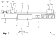
- FIGS. 3 through 12 are block diagrams of an additive manufacturing system ( 200 ) depicting a process performed by the additive manufacturing system ( 200 ), according to an example of the principles described herein.
- the additive manufacturing system ( 200 ) of FIGS. 3 through 12 may include the elements described above in connection with FIGS. 1 and 2 , and reference to similar elements are described herein in connection with FIGS. 1 and 2 .
- the build platform ( 202 ) may be supported by build platform base ( 203 ).
- the build platform ( 202 ) and/or the build platform base ( 203 ) may be moveably coupled to the stage ( 204 ) to allow for the build platform ( 202 ) and the build platform base ( 203 ) to be moved up and down in order to form layers of the 3D object with the build material ( 150 ) and the agent.
- the material spreader ( 120 ) and the hoppers ( 140 ) which form the build material dispensing device ( 100 ) are moveably coupled to the carriage ( 201 ).
- the carriage ( 201 ) traverses a length of the additive manufacturing system ( 200 ) so that the build material dispensing device ( 100 ) may move over the entirety of the build platform ( 202 ).
- the carriage ( 201 ) may include a carriage drive shaft, a carriage coupling device and other devices to couple a material spreader ( 120 ), the hoppers ( 140 ), an energy emitting device ( 160 ), an agent dispenser ( 180 ), or combinations thereof.
- a plurality of carriages ( 201 ) may be included on the build material dispensing device ( 100 ) and the additive manufacturing system ( 200 ) to move the material spreader ( 120 ), the hoppers ( 140 ), an energy emitting device ( 160 ), and an agent dispenser ( 180 ), independently or collectively.
- the additive manufacturing system ( 200 ) may also include an energy emitting device ( 160 ).
- the energy emitting device ( 160 ) is moveably coupled to the carriage ( 201 ) and may move along with the build material dispensing device ( 100 ) in order to warm the build material ( 150 ) and/or fuse, bind, or cure the build material ( 150 ).
- the energy emitting device ( 160 ) may be any device that emits electromagnetic energy at any wavelength to warm or fuse, or cure one or more of the build material ( 150 ); an agent; and a combination of build material and agent.
- the energy emitting device ( 160 ) may include at least one warming lamp ( 161 ) that emits electromagnetic energy sufficient to warm the build material ( 150 ) deposited or spread along the surface of the stage ( 204 ) and the build platform ( 202 ). Warming of the build material ( 150 ) serves to prepare the build material ( 150 ) for solidification including, for example binding or thermal fusing. Further, the electromagnetic radiation from the warming lamp ( 161 ) serves to maintain the build material ( 150 ) and the object being formed from the build material ( 150 ) at a relatively more uniform and non-fluctuating temperature. In the case of thermal binding systems, if the build material ( 150 ) and the object being formed are allowed to cool or otherwise fluctuate in temperature, the object or layers thereof may become warped.
- the energy emitting device ( 160 ) may also include at least one fusing lamp ( 163 ).
- the fusing lamp ( 163 ) emits electromagnetic energy sufficient to fuse the build material ( 150 ) together through the use of the agent. Fusing of the build material a layer at a time serves to form a 3D object.
- the fusing lamp ( 163 ) may fuse the build material ( 150 ) where the agent has been printed and in all coordinate directions within the 3D object including between layers of fused build material ( 150 ) by allowing the warming lamp ( 161 ) to keep previous, solidified layers at a fusible temperature and fusing the build material ( 150 ) spread across the previous, fused layer to fuse to the layer of build material ( 150 ) to the previous layer.
- the energy emitting device ( 160 ) may include one warming lamp ( 161 ) and three fusing lamps ( 163 ). In one example, the fusing lamps ( 163 ) may remain on or activated during a four-pass process described herein.
- the build material ( 150 ), without fusing or agents deposited thereon, may only absorb a small amount of energy from the fusing lamps.
- the voltage to the fusing lamps ( 163 ) may be lowered when the build platform ( 202 ) is being warmed or a fusing or binding process is not being performed in order to reduce power consumption.
- the additive manufacturing system ( 200 ) may also include an agent dispenser ( 180 ) to dispense a binding or fusing agent onto build material ( 150 ) spread along the surface of the build platform ( 202 ).
- the agent dispenser ( 180 ) may be moveably coupled to the carriage ( 201 ), and may move with the build material dispensing device ( 100 ) and the energy emitting device ( 160 ) over the surface of the build platform.
- the agent dispenser ( 180 ) may include at least one fluidic die ( 181 - 1 , 181 - n , collectively referred to herein as 181 ) used to dispense a volume of the agent onto the build material ( 150 ). In the examples of FIGS.
- the agent dispenser ( 180 ) includes two fluidic die ( 181 - 1 , 181 - n ), but may include any number of fluidic die ( 181 ) as denoted by the “n” in 181 - n .
- the fluidic die ( 181 ) may be digitally addressable such that the agent may be dispensed on the build material ( 150 ) that is spread across the surface of the build platform ( 202 ) in a pattern as defined by object data ( 322 ) provided to the additive manufacturing system ( 200 ).
- the fusing lamp ( 163 ) will fuse the build material ( 150 ) and form a layer of the 3D object.
- the additive manufacturing system ( 200 ) may also include logic and circuitry to cause the material spreader ( 120 ), the hoppers ( 140 ), energy emitting device ( 160 ), the agent dispenser ( 180 ), and the build platform ( 202 ) and the build platform base ( 203 ) to move and actuate in a manner that produces a 3D object based on object data ( 322 ) stored in a data storage device ( 321 ) of the additive manufacturing system ( 200 ).
- the additive manufacturing system ( 200 ) may include a controller ( 320 ).
- the controller ( 320 ) may include the hardware architecture to retrieve executable code from the data storage device ( 321 ) and execute the executable code.
- the executable code may, when executed by the controller ( 320 ), cause the controller ( 320 ) to implement at least the functionality of sending signals to the material spreader ( 120 ), the hoppers ( 140 ), energy emitting device ( 160 ), the agent dispenser ( 180 ), and the build platform ( 202 ) and the build platform base ( 203 ) to instruct these devices to perform their individual functions according to the methods of the present specification described herein.
- the controller ( 320 ) may receive input from and provide output to a number of the remaining hardware units.
- the object data ( 322 ) stored in the storage device ( 321 ) may be obtained from an external source such as, for example, a computer-aided design (CAD) system that provides a CAD model of the 3D object defined by the object data ( 322 ).
- the build layer process ( 323 ) may be any data stored in the data storage device ( 321 ) that defines the process the controller ( 320 ) follows in instructing the material spreader ( 120 ), the hoppers ( 140 ), energy emitting device ( 160 ), the agent dispenser ( 180 ), and the build platform ( 202 ) and the build platform base ( 203 ) to produce the 3D object over a number of build material ( 150 ) and agent layers.
- CAD computer-aided design
- a first hopper ( 140 - 1 ) for dispensing the build material ( 150 ) may be located in front of the material spreader ( 120 ) with respect to the positive X-direction indicated by arrow ( 190 ).
- the additive manufacturing system ( 200 ) may also include a second hopper located behind the material spreader ( 120 ) with respect to the positive X-direction indicated by arrow ( 190 ).
- a hopper ( 140 ) may be located in front of and behind the material spreader ( 120 ) irrespective of the direction of travel of the build material dispensing device ( 100 ).
- the material spreader ( 120 ) may include a material spreading roller that counter-rotates such that it rotates in a direction opposite to its movement relative to the build platform.
- a material spreading roller that counter-rotates such that it rotates in a direction opposite to its movement relative to the build platform.
- the distance between the material spreading roller ( 120 ) and the surfaces of the stage ( 204 ) and build platform ( 202 ) may be adjustable within a number of layers of dispensed build material ( 150 ), between the layers of dispensed build material ( 150 ), or combinations thereof. In this manner, the thickness of the layer of build material ( 150 ) may be varied.
- the distance between the material spreading roller ( 120 ) and the surfaces of the stage ( 204 ) and build platform ( 202 ) may be adjustable to allow the material spreading roller ( 120 ) to be lifted from a spreading distance where the build material ( 150 ) is spread to a non-contact distance where the material spreading roller ( 120 ) does not come in contact with any other element within the additive manufacturing system ( 200 ). This allows the material spreading roller ( 120 ) to skip or jump over large amounts of build material ( 150 ) that may be dispensed by the hoppers ( 140 ) on, for example, the stage ( 204 ) or the build platform ( 202 ).
- the hoppers ( 140 ) may include a plurality of doctor blades coupled to a dispense end of the hoppers ( 140 ).
- the doctor blades serve to assist in the spreading the build material ( 150 ) dispensed on the stage ( 204 ) and the build platform ( 202 ).
- the doctor blades may serve as the build material spreader, and the additive manufacturing system ( 200 ) may not include a rotating material spreader ( 120 ) as depicted in FIGS. 3 through 12 .
- the additive manufacturing system ( 200 ) may include both the material spreader ( 120 ) as depicted in FIGS. 3 through 12 and the doctor blades.
- the first hopper ( 140 - 1 ) and the second hopper ( 140 - 2 ) may dispense the build material ( 150 ) in front of and behind the material spreader ( 120 ) in at least one direction of travel, and, in some examples, may dispense build material ( 150 ) in both the positive and negative x-directions of travel as indicated by arrow ( 190 ).
- the hoppers ( 140 ) to dispense build material ( 150 ) during any pass of the material dispensing device ( 100 ) over the build platform ( 202 ) bidirectionally, and may reduce the number of passes over the build platform ( 202 ) reducing the time per layer of material that it takes to build the 3D object. Further, less passes over the build platform ( 202 ) also reduces or eliminates fluctuations in temperature of the build material ( 150 ) and successive layers of fused build material that form the 3D object.
- the state of the additive manufacturing system ( 200 ) depicted in FIG. 3 may be an initial state before a first layer of build material ( 150 ) is deposited on the stage ( 204 ) and build platform ( 202 ) or between deposition and binding of successive layers of the build material ( 150 ).
- FIG. 4 depicts the additive manufacturing system ( 200 ) in a state in which the build material ( 150 ) is deposited on the build platform ( 202 ).
- the build platform ( 202 ) and build platform base ( 203 ) may be moved downward in the z-direction as indicated by arrow ( 191 ) to provide for the layer of build material ( 150 ) to be formed on the build platform ( 202 ), and, in one example, to approximately the level of the stage ( 204 ).
- the warming lamp ( 161 ) may be actuated and its warming electromagnetic radiation ( 162 ) may be used to warm the build platform ( 202 ) and the environment around the build platform ( 202 ) to assist in maintaining the build material ( 150 ) at a more consistent temperature.
- the fusing lamp ( 163 ) and its fusing electromagnetic radiation ( 164 ) may not be activated since an agent has not been dispensed on the layer of build material ( 150 ).
- the first hopper ( 140 - 1 ) and the second hopper ( 140 - 2 ) both dispense build material ( 150 ) in front of and behind the material spreader ( 120 ), respectively.
- the This allows for additional amounts or doses of the build material ( 150 ) to be made available to the material spreader ( 120 ) for spreading across the build platform ( 202 ), and maintains a constant amount of build material ( 150 ) in front of the material spreader ( 120 ) during any and all passes of the material dispensing device ( 100 ).
- a subsequent pass of the material spreader ( 120 ) over the build platform ( 202 ) may be made to ensure that a uniformly smooth and even layer of build material is deposited and formed on the build platform ( 202 ). Allowing both the first hopper ( 140 - 1 ) and the second hopper ( 140 - 2 ) to dispense building material ( 150 ) in both directions of travel enables accurate control of the amount of build material ( 150 ) spread in both directions of travel of the material dispensing device ( 100 ).
- first hopper ( 140 - 1 ) and the second hopper ( 140 - 2 ) to dispense building material ( 150 ) allows for maintaining building material ( 150 ) spread dynamics such as even spreading of the build material ( 150 ) throughout a spread process.
- the inclusion of hoppers ( 140 ) on either side of the material spreader ( 120 ) improves system productivity due to a reduced number of passes over the build platform ( 202 ) used to spread the build material ( 150 ) bidirectionally. Bidirectional spreading reduces the risk of the 3D object shifting with respect to the build platform ( 202 ), and may improve build material spread quality.
- Dispensing from hoppers ( 140 ) simultaneously while the carriage ( 201 ) translates across the build platform ( 202 ) in either direction may help maintain build temperature uniformity as the build material ( 150 ) spread from the rear hopper will insulate the previous layer.
- the forward hopper with respect to the direction of travel of the material dispensing device ( 100 ), may dispense bidirectionally without the rear hopper dispensing at the same time or during the same pass over the build platform ( 202 ).
- the additive manufacturing system ( 200 ) may be in a state where the material dispensing device ( 100 ) has completed a first build material ( 150 ) dispensing pass along with a simultaneous first warming pass.
- the warming lamp ( 161 ) and its warming electromagnetic radiation ( 162 ) may continue to warm the stage ( 204 ) and any build material ( 150 ) dispensed thereon in preparation of a second dispensing and spreading pass.
- the carriage ( 201 ) may, at this point, cause the material spreader ( 120 ) to lift up in the positive z-direction as indicated by arrow ( 191 ) as it passes the edge of the build platform ( 202 ) from left to right so that any build material ( 150 ) dispensed by the hopper ( 140 - 1 ) may not be further spread across the right side of the stage ( 204 ).
- the material spreader ( 120 ) may skip over any build material ( 150 ) dispensed by the hopper ( 140 - 1 ), and spread that build material ( 150 ) dispensed by the hopper ( 140 - 1 ) during the next pass from the right to the left over the build platform ( 202 ).
- the second pass of building material ( 150 ) is depicted including additional build material ( 150 ) being dispensed by the first hopper ( 140 - 1 ) and the second hopper ( 140 - 2 ) behind and in front of the material spreader ( 120 ), respectfully.
- additional build material ( 150 ) may be made. Dispensing from hopper ( 140 - 1 ) in this example, may risk build material ( 150 ) contacting with the fluidic die ( 181 ) of the agent dispenser ( 180 ).
- the build material ( 150 ) may be dispensed from both hoppers ( 140 - 1 , 140 - 2 ) in order to speed up the dispense process.
- an additional pass of the material spreader ( 120 ) may be made.
- hopper ( 140 - 2 ) may dispense build material ( 150 ) as the agent dispenser ( 180 ) is following without the first hopper ( 140 - 1 ) dispensing build material ( 150 ).
- the material spreader ( 120 ) in this pass is rotating in the direction of arrow B so that it counter-rotates relative to the direction of travel of the material dispensing device ( 100 ).
- the warming lamp ( 161 ) may remain on during this second pass to heat the build material ( 150 ) already dispensed and the build material ( 150 ) that is dispensed in this second pass.
- the material spreader ( 120 ) rotates in the direction of arrow B so that it is counter-rotating with respect to the direction of travel from the right to the left.
- the agent dispenser ( 180 ) begins to move from its home position to the right of the build platform ( 202 ), in the left direction along with the energy emitting device ( 160 ) and the build material dispensing device ( 100 ) in preparation for dispensing an amount of agent ( 185 ) onto the twice dispensed and spread build material ( 150 ) on the build platform ( 202 ).
- the agent dispenser ( 180 ) dispenses the agent ( 185 ) in a pattern onto the building material ( 150 ) in its first pass over the build platform ( 202 ) and second pass of the energy emitting device ( 160 ) and the build material dispensing device ( 100 ) over the build platform ( 202 ).
- the agent dispenser ( 180 ) completes its first pass over the build platform ( 202 ) while dispensing the agent ( 185 ), and begins a second pass over the build platform ( 202 ) to dispense another amount of the agent ( 185 ).
- the deposition of the agent ( 185 ) during this second pass of the agent dispenser ( 180 ) may or may not be performed during the first pass of the agent dispenser ( 180 ) and its deposition of the agent ( 185 ) during that first pass may be sufficient in some examples.
- the agent dispenser ( 180 ) dispenses agent ( 185 ) during both of its passes over the build platform ( 202 ).
- the agent dispenser ( 180 ) dispenses the agent ( 185 ) within a target area of the build platform ( 202 ) that is smaller than the full length and width of the build platform ( 202 ).
- the fusing lamp ( 163 ) may be activated to cause its fusing electromagnetic radiation ( 164 ) to fuse or bind or cure the build material ( 150 ) together through the use of the agent ( 185 ).
- the fusing lamps ( 163 ) may be activated over a plurality of passes when fusing is not taking place, and may be provided a lower voltage instead.
- the activation of the fusing lamps ( 163 ) may refer to a use of the fusing lamps ( 163 ) at a sufficient voltage to fuse, bind, or cure the build material ( 150 ).
- the hoppers ( 140 ) may dispense an amount of build material ( 150 ) and the material spreader ( 120 ) may spread that deposited build material ( 150 ).
- the fusing lamp ( 163 ) may be activated in a subsequent pass back to the left, in another example the hoppers ( 140 ) may not dispense build material ( 150 ) and the material spreader ( 120 ) may not activate in this third pass.
- the carriage ( 201 ) may lift the material spreader ( 120 ) so that it does not contact the build material ( 150 ).
- the energy emitting device ( 160 ) may also activate its warming lamp ( 161 ) to emit its warming electromagnetic radiation ( 162 ) to keep the build material ( 150 ), fused layers of the 3D object, and the surrounding environment at a consistent temperature.
- the material dispensing device ( 100 ), the energy emitting device ( 160 ), and the agent dispenser ( 180 ) return to the right of the build platform ( 202 ) completing its third pass.
- the agent dispenser ( 180 ) is left on the right side of the build platform ( 202 ), and the material dispensing device ( 100 ) and energy emitting device ( 160 ) make a fourth pass over the build platform ( 202 ), As the material dispensing device ( 100 ) and energy emitting device ( 160 ) make this fourth pass as depicted in FIG.
- the fusing lamp ( 163 ) may be again activated during this fourth pass to again cause its fusing electromagnetic radiation ( 164 ) to fuse or bind or cure the build material ( 150 ) together through the use of the agent ( 185 ).
- This second fusing or binding pass may assist in ensuring that the entirety of the build material ( 150 ) that is exposed to the agent ( 185 ) is fused.
- the material dispensing device ( 100 ) and energy emitting device ( 160 ) return back to the initial position they were in as depicted in FIG. 3 .
- the process of FIGS. 3 through 12 may be performed any number of iterations in order to form a 3D object.
- the fusing lamp ( 163 ) may be again activated for a third time during this subsequent first pass to again cause its fusing electromagnetic radiation ( 164 ) to fuse or bind the build material ( 150 ) together through the use of the agent ( 185 ).
- the process of FIGS. 3 through 12 may include a number of processes using the material spreader ( 120 ), the hoppers ( 140 ), energy emitting device ( 160 ), and the agent dispenser ( 180 ) and may include a number of sub-processes effected by these devices.
- the first pass may include a fusing process using the fusing lamp ( 163 ) to fuse build material ( 150 ) from a previous layer formation for a third time.
- This first pass may also include a warming process using the warming lamp ( 161 ), and a build material ( 150 ) deposition and spreading process using the material spreader ( 120 ) and hoppers ( 140 ) of the material dispensing device ( 100 ).
- the second pass may include a second build material ( 150 ) deposition and spreading process, a second warming process, and a first agent ( 185 ) dispensing process using the agent dispenser ( 180 ).
- the third pass may include a second agent ( 185 ) dispensing process, a second fusing process using the fusing lamp ( 163 ), and a third warming process using the warming lamp ( 161 ).
- the fourth pass may include a fourth warming process using the warming lamp ( 161 ) and a third fusing process. In this manner, a single layer of the 3D object may be formed, and the process may be performed a number of times to form subsequent layers of the 3D object. Between instantiations of this four-pass process, the build platform ( 202 ) may move down with respect to arrow ( 191 ) to accommodate for the layers of build material ( 150 ) added and fused within the 3D object.
- FIG. 13 is a diagram of a hopper ( 140 ) to dispense a build material ( 150 ) onto a build platform ( 202 ) of an additive manufacturing system ( 200 ), according to an example of the principles described herein.
- the hopper ( 140 ) may include a material storage area ( 1301 ) to store the build material ( 150 ),
- the material storage area ( 1301 ) may include a storage area outlet ( 1302 ) to allow the build material ( 150 ) contained in the material storage area ( 1301 ) to exit the material storage area ( 1301 ).
- the hopper ( 140 ) may also include a rotary doser ( 1303 ) rotatably coupled to a manifold ( 1304 ).
- the manifold ( 1304 ) may include a manifold inlet ( 1305 ) and a manifold outlet ( 1306 ) to allow build material to enter and exit the rotary doser ( 1303 ).
- the rotary doser ( 1303 ) may include a number of doser voids ( 1307 - 1 , 1307 - n , collectively referred to herein as 1307 ), and may rotate in either direction or both directions to dispense build material ( 150 ).
- the doser voids ( 1307 ) may serve to contain an amount of build material ( 150 ) that is dispensed to the rotary doser ( 1303 ) from the material storage area ( 1301 ) through the storage area outlet ( 1302 ) and the manifold inlet ( 1305 ).
- the doser voids ( 1307 ) may be shaped to contain a measured amount of the build material so that when the rotary doser ( 1303 ) rotates and dispenses the build material ( 150 ) through the manifold outlet ( 1306 ) when it is rotated to the bottom of the hopper ( 140 ), a known amount of build material ( 150 ) is dispensed onto the stage ( 204 ) and/or the build platform ( 202 ).
- the speed at which the rotary doser is rotated may be varied, or changed, to modify the rate at which build material is dispensed from the hopper ( 140 ).
- the hopper ( 140 ) may also include a number of doctor blades ( 1308 - 1 , 1308 - 2 , collectively referred to herein as 1308 ) coupled to the bottom of the manifold ( 1304 ),
- the doctor blades ( 1308 ) may be used to assist the spreading the build material ( 150 ) dispensed on the stage ( 204 ) and the build platform ( 202 ).
- the doctor blades ( 1308 ) may serve as the build material spreader, and the additive manufacturing system ( 200 ) may not include the rotating material spreader ( 120 ) as depicted in FIGS. 3 through 12 .
- the additive manufacturing system ( 200 ) may include both the material spreader ( 120 ) as depicted in FIGS.
- a doctor blade ( 1308 ) may be included on a front and back side of the manifold ( 1304 ) relative to a direction of travel along the carriage ( 201 ) to allow for a doctor blade ( 1308 ) to always be able to spread the build material out in front of the direction of movement of the hopper ( 140 ) whether the direction of travel is to the right or to the left as depicted in FIGS. 3 through 12 .
- the hopper ( 140 ) may also include an air vent ( 1309 ) used to vent air into the material storage area ( 1301 ).
- the material storage area ( 1301 ) may be sealed such that air may not be able to pass into the material storage area ( 1301 ) when material is dispensed therefrom.
- the air vent ( 1309 ) allows for air to replace the dispensed build material ( 150 ) and relieve any pressure that may otherwise exist in the material storage area ( 1301 ).
- the hoppers ( 140 ) of the additive manufacturing system ( 200 ) may also include a number of heating elements ( 1311 ) to heat the build material ( 150 ) therein. Pre-heating the build material ( 150 ) helps to ensure that the formed layers of the 3D object do not warp.
- the hopper ( 140 ) may include a door ( 1310 ) that may be opened to access the material storage area ( 1301 ). This door may be used to refill the material storage area ( 1301 ) with build material ( 150 ).
- FIG. 14 is a diagram of a build material refill station ( 1400 ) to refill the hopper ( 140 ) of FIG. 13 , according to an example of the principles described herein.
- FIG. 15 is a diagram of the hopper ( 140 ) of FIG. 13 and the build material refill station ( 1400 ) of FIG. 14 , according to an example of the principles described herein.
- the build material refill station ( 1400 ) may include a material storage area ( 1401 ) to store the build material ( 150 ) in preparation to dispense that build material ( 150 ) in to the hopper.
- the material storage area ( 1401 ) may include a storage area outlet ( 1402 ) to allow the build material ( 150 ) contained in the material storage area ( 1401 ) to exit the material storage area ( 1401 ).
- the build material refill station ( 1400 ) may also include a rotary doser ( 1403 ) rotatably coupled to a manifold ( 1404 ).
- the manifold ( 1403 ) may include a manifold inlet ( 1405 ) and a manifold outlet ( 1406 ) to allow build material ( 150 ) to enter and exit the rotary doser ( 1403 ).
- the rotary doser ( 1403 ) may include a number of doser voids ( 1407 - 1 , 1407 - n , collectively referred to herein as 1407 ), and may rotate in either direction or both directions to dispense build material ( 150 ),
- the doser voids ( 1407 ) may serve to contain an amount of build material ( 150 ) that is dispensed to the rotary doser ( 1403 ) from the material storage area ( 1401 ) through the storage area outlet ( 1402 ) and the manifold inlet ( 1405 ).
- the doser voids ( 1407 ) may be shaped to contain a measured amount of the build material so that when the rotary doser ( 1403 ) rotates and dispenses the build material ( 150 ) through the manifold outlet ( 1406 ) when it is rotated to the bottom of the build material refill station ( 1400 ), a known amount of build material ( 150 ) is dispensed into the hopper ( 140 ) that the build material refill station ( 1400 ) is refilling.
- the build material refill station ( 1400 ) may also include an air vent ( 1409 ) used to vent air into the material storage area ( 1301 ),
- the material storage area ( 1401 ) may be sealed such that air may not be able to pass into the material storage area ( 1401 ) when material is dispensed therefrom.
- the air vent ( 1409 ) allows for air to replace the dispensed build material ( 150 ) and relieve any pressure that may otherwise exist in the material storage area ( 1401 ).
- the build material refill station ( 1400 ) of the additive manufacturing system ( 200 ) may also include a number of heating elements ( 1411 ) to heat the build material ( 150 ) therein. Pre-heating the build material ( 150 ) helps to ensure that the formed layers of the 3D object do not warp.
- the build material refill station ( 1400 ) may include a pre-stage area ( 1423 ) located at the manifold outlet ( 1406 ).
- the build material ( 150 ) contained within the doser voids ( 1407 ) may fall into the pre-stage area ( 1423 ) above the closed dispense door ( 1420 ) waiting for the dispense lever ( 1421 ) to be actuated to allow that portion of build material ( 150 ) in the pre-stage area ( 1423 ) to be dispensed from the pre-stage area ( 1423 ) and the manifold outlet ( 1406 ) into the hoppers ( 140 ).
- the build material refill station ( 1400 ) may also include a dispense door ( 1420 ) pivotably coupled to the manifold ( 1404 ).
- a dispense lever ( 1421 ) is coupled to the dispense door ( 1420 ) such that when a force is applied to the dispense lever ( 1421 ), the dispense door ( 1420 ) opens, and the build material contained in the doser void ( 1407 ) closest to the dispense door ( 1420 ) may be dispensed into the hopper ( 140 ).
- the manifold ( 1404 ) may include a catch ( 1422 ) coupled thereto that interfaces with the door ( 1310 ) of the hopper ( 140 ), and forces the door ( 1310 ) open in the direction of arrow ( FIG. 13, 1330 ) as the hopper ( 140 ) is moved in the direction of arrow ( 1501 ).
- a catch ( 1422 ) coupled thereto that interfaces with the door ( 1310 ) of the hopper ( 140 ), and forces the door ( 1310 ) open in the direction of arrow ( FIG. 13, 1330 ) as the hopper ( 140 ) is moved in the direction of arrow ( 1501 ).
- the door ( 1310 ) interfaces with the catch ( 1422 ) and the door is forced open.
- the dispense lever ( 1421 ) interfaces with a surface of the hopper ( 140 ) causing the dispense door ( 1420 ) to pivot open and dispense build material ( 150 ) from the doser void ( 1407 ) closest to the dispense door ( 1420 ). In this manner, the hopper ( 140 ) may be refilled.
- the amount of build material ( 150 ) contained in a doser void ( 1407 ) may not be enough to completely fill the hopper ( 140 ).
- the build material refill station ( 1400 ) may be placed to the left of the build platform ( 202 ) as depicted in FIGS. 3 through 12 . In this orientation, the hoppers ( 140 ) may interface with the build material refill station ( 1400 ) when they move from the right to the left during any one of their return passes over the build platform ( 202 ).
- the hoppers ( 140 ) This allows the hoppers ( 140 ) to receive a smaller amount of build material ( 150 ) from the build material refill station ( 1400 ) as the hoppers ( 140 ) themselves dispense build material ( 150 ) much like “taking a sip” of build material ( 150 ) from the build material refill station ( 1400 ) rather than refiling entirely each time.
- the hoppers ( 140 ) By allowing the hoppers ( 140 ) to be refiled using relatively small amounts, the hoppers ( 140 ) do not become too heavy to move along the carriage ( 201 ), and can dispense their build material ( 150 ) without any strain on mechanical elements of the carriage ( 201 ) effecting the manner in which the hoppers ( 140 ) dispense the build material ( 150 ).
- a single build material refill station ( 1400 ) may be used to refill both hoppers ( 140 - 1 , 140 - 2 ) in the additive manufacturing system ( 200 ).
- the second hopper ( 140 - 2 ) may first receive build material ( 150 ) from the build material refill station ( 1400 ), and push past the dispense lever ( 1421 ) to allow the first hopper ( 140 - 1 ) to then interface with the dispense lever ( 1421 ).
- the dispense lever ( 1421 ) may be resilient enough to cause the dispense door ( 1420 ) to open, but elastic enough to allow the second hopper ( 140 - 2 ) to push past it, or it may be hinged such that the dispense lever ( 1421 ) may turn a full 90 degrees to allow the second hopper ( 140 - 2 ) to push past it.
- the additive manufacturing system ( 200 ) may include two build material refill stations ( 1400 ) to allow the two hoppers ( 140 - 1 , 140 - 2 ) to be refilled.
- FIG. 16 is a flowchart depicting a method ( 1600 ) of supplying build material ( 150 ) to an additive manufacturing system ( 200 ), according to an example of the principles described herein.
- the method ( 1600 ) may include, with a first build material dispensing hopper ( 140 - 1 ), dispensing (block 1601 ) a volume of build material ( 150 ) onto the build platform ( 202 ) in front of the material spreading roller ( 120 ) with respect to a least one direction of travel as indicated by arrow ( 190 ) in FIGS. 1 through 12 .
- the first hopper ( 140 - 1 ) may dispense any number of doses or any amount of build material ( 150 ) along a pass over the build platform ( 202 ) including a plurality of doses of the build material ( 150 ),
- the method ( 1600 ) may further include, with the second build material dispensing hopper ( 140 - 2 ), dispensing (block 1602 ) a volume of the build material ( 150 ) onto the build platform ( 202 ) behind the material spreading roller ( 120 ) with respect to the a least one direction of travel. This allows for additional build material ( 150 ) to be spread across the build platform ( 202 ) in subsequent passes over the build platform ( 202 ) which results in a more uniform spreading of build material ( 150 ).
- the spreading of the build material ( 150 ) over the build platform ( 202 ) may be more effective and efficient as fewer passes are used to appropriately spread the build material ( 150 ) over the build platform ( 202 ). Because the material spreader ( 120 ) rotates in two directions, and counter-rotates with respect to its direction of travel, the material spreader ( 120 ) may effectively utilize the build material ( 150 ) dispensed by both hoppers ( 140 - 1 , 140 - 2 ) to completely and uniformly cover the build platform ( 202 ) in preparation for a dispensing of agent from the agent dispenser ( 180 ) and a fusing process from a fusing lamp ( 163 ) of the energy emitting device ( 160 ).
- FIG. 17 is a flowchart depicting a method ( 1700 ) of supplying build material ( 150 ) to an additive manufacturing system ( 200 ), according to another example of the principles described herein.
- Blocks 1701 through 1703 of FIG. 17 are identical to blocks 1601 through 1603 of FIG. 16 , and their description is provided above in connection with FIG. 16 .
- the method of FIG. 17 may further include, with a warming lamp ( 161 ) of the energy emitting device ( 160 ), warming the build material ( 150 ) on each of a number of passes of the material spreading roller ( 120 ) over the build platform ( 202 ).
- the build material ( 150 ) By regularly warming the build material ( 150 ) with the warming lamp ( 161 ), the build material ( 150 ), fused portions of the build material, and the environment therearound may be maintained at a consistent temperature. Maintaining a consistent temperature among the elements involved in forming the 3D object ensures that the 3D object is not subjected to temperature fluctuations that may cause layers of the 3D object to warp or become distorted.
- the hoppers ( 140 ) and the material spreader ( 120 ) may be coupled to separate carriages ( 201 ).
- the hoppers ( 140 ) may dispense volumes of build material ( 150 ) at different locations on the build platform ( 202 ) for spreading by the material spreader ( 120 ).
- the hoppers ( 140 ) in this example may move independently of the material spreader ( 120 ), and dose build material ( 150 ) at any location and at any time that allows for the most effective use of the build material ( 150 ) by the material spreader ( 120 ).
- the specification and figures describe a build material dispensing device in an additive manufacturing system.
- the build material dispensing device may include a material spreader to spread an amount of build material along a build platform, and at least one hopper for dispensing the build material.
- the at least one hopper dispenses a plurality of doses of the build material in front of the progression of the material spreader as the material spreader is moved over the build platform.
- the build material dispensing device may maintain a consistent amount of build material in front of the material spreader during each pass of the build material dispensing device over a build platform, and provides for the dispensing of a number of doses or any amount of build material to maintain build material spread dynamics throughout the spread process.
- the build material dispensing device provides for the accurate control of the amount of build material spread in either direction of travel of the build material dispensing device along a carriage. Further, the build material dispensing device allows for multi-pass dispensing of layers of the build material.
- the build material dispensing device enables single pass multi-height spreading of the build material which improves the uniformity of the density of the layers of build material spread along the build platform. Further, the non-aggressive build material transfer provided by the build material dispensing device reduces risk of electrical charging of the build material, which may have unpredictable results. Further, swappable hoppers allow a widened range of materials such as metals to be accurately deposited to the build platform, and each dispenser is tuned for at least one, and in some examples, a plurality of different materials.
- pre-heating of the build material directly before dispensing to the build platform using heaters in the hoppers and the build material refill station, and during deposition of the build material on the build platform using the warming lamp allows for tightened control of the temperature of the build material and its surrounding environment.
Landscapes
- Engineering & Computer Science (AREA)
- Chemical & Material Sciences (AREA)
- Materials Engineering (AREA)
- Manufacturing & Machinery (AREA)
- Mechanical Engineering (AREA)
- Physics & Mathematics (AREA)
- Optics & Photonics (AREA)
- Nozzles (AREA)
- Powder Metallurgy (AREA)
Applications Claiming Priority (1)
| Application Number | Priority Date | Filing Date | Title |
|---|---|---|---|
| PCT/US2018/015147 WO2019147239A1 (en) | 2018-01-25 | 2018-01-25 | Build material dispensing device |
Related Parent Applications (1)
| Application Number | Title | Priority Date | Filing Date |
|---|---|---|---|
| PCT/US2018/015147 A-371-Of-International WO2019147239A1 (en) | 2018-01-25 | 2018-01-25 | Build material dispensing device |
Related Child Applications (1)
| Application Number | Title | Priority Date | Filing Date |
|---|---|---|---|
| US17/547,908 Continuation US11607849B2 (en) | 2018-01-25 | 2021-12-10 | Build material dispensing device |
Publications (2)
| Publication Number | Publication Date |
|---|---|
| US20200346408A1 US20200346408A1 (en) | 2020-11-05 |
| US11225022B2 true US11225022B2 (en) | 2022-01-18 |
Family
ID=67394808
Family Applications (2)
| Application Number | Title | Priority Date | Filing Date |
|---|---|---|---|
| US16/608,430 Active US11225022B2 (en) | 2018-01-25 | 2018-01-25 | Build material dispensing device |
| US17/547,908 Active US11607849B2 (en) | 2018-01-25 | 2021-12-10 | Build material dispensing device |
Family Applications After (1)
| Application Number | Title | Priority Date | Filing Date |
|---|---|---|---|
| US17/547,908 Active US11607849B2 (en) | 2018-01-25 | 2021-12-10 | Build material dispensing device |
Country Status (4)
| Country | Link |
|---|---|
| US (2) | US11225022B2 (zh) |
| EP (1) | EP3691864A4 (zh) |
| CN (1) | CN111465483B (zh) |
| WO (1) | WO2019147239A1 (zh) |
Cited By (1)
| Publication number | Priority date | Publication date | Assignee | Title |
|---|---|---|---|---|
| US20220118522A1 (en) * | 2020-10-20 | 2022-04-21 | Sodick Co., Ltd. | Additive manufacturing apparatus |
Families Citing this family (4)
| Publication number | Priority date | Publication date | Assignee | Title |
|---|---|---|---|---|
| US11400519B2 (en) * | 2018-03-29 | 2022-08-02 | Arcam Ab | Method and device for distributing powder material |
| CN110576607B (zh) * | 2019-08-19 | 2021-06-29 | 河海大学常州校区 | 一种功能梯度结构的slm增材制造设备 |
| US20230013520A1 (en) * | 2021-07-14 | 2023-01-19 | Sakuu Corporation | Three-dimensional ("3d") printing apparatus with counter-rotating roller |
| CN113600836B (zh) * | 2021-08-27 | 2024-02-20 | 阿呆云链科技(宁波)有限公司 | 一种发动机缸盖3d打印装置 |
Citations (24)
| Publication number | Priority date | Publication date | Assignee | Title |
|---|---|---|---|---|
| BE825242A (fr) | 1975-02-06 | 1975-05-29 | Nouveau doseur | |
| US5934343A (en) | 1997-03-31 | 1999-08-10 | Therics, Inc | Method for dispensing of powders |
| US20070282477A1 (en) | 2006-05-31 | 2007-12-06 | Kilian Schmidt | Method and system for controlling process tools by interrupting process jobs depending on job priority |
| WO2013178825A2 (fr) | 2012-06-01 | 2013-12-05 | Compagnie Generale Des Etablissements Michelin | Machine et procédé pour la fabrication additive à base de poudre |
| CN103738747A (zh) | 2013-12-13 | 2014-04-23 | 大连理工大学 | 一种移动料斗式粉床铺粉装置及方法 |
| CN104010750A (zh) | 2011-12-20 | 2014-08-27 | 米其林集团总公司 | 用于粉末基增材制造的机器和方法 |
| US20150057784A1 (en) | 2013-08-21 | 2015-02-26 | Microsoft Corporation | Optimizing 3d printing using segmentation or aggregation |
| US20150130101A1 (en) | 2013-11-12 | 2015-05-14 | John D. Fiegener | Method and apparatus for feeding print material |
| CN204565115U (zh) | 2015-05-05 | 2015-08-19 | 北京易博三维科技有限公司 | 一种激光粉末快速成形机精量铺粉装置 |
| US20150258706A1 (en) * | 2014-03-14 | 2015-09-17 | Seiko Epson Corporation | Three-dimensional structure manufacturing apparatus, manufacturing method of three-dimensional structure, and three-dimensional structure |
| US20160121399A1 (en) | 2014-06-20 | 2016-05-05 | Velo3D, Inc. | Apparatuses, systems and methods for three-dimensional printing |
| WO2016146095A1 (de) | 2015-03-17 | 2016-09-22 | Voxeljet Ag | Verfahren und vorrichtung zum herstellen von 3d-formteilen mit doppelrecoater |
| WO2016161489A2 (en) | 2015-04-09 | 2016-10-13 | "Print Cast" Ltd | Method and system for layer-wise generation of three-dimensional models from powdered material |
| US20170008230A1 (en) | 2014-02-25 | 2017-01-12 | Seiichi YUYAMA | 3D Printer |
| WO2017008891A1 (de) | 2015-07-13 | 2017-01-19 | Eos Gmbh Electro Optical Systems | Verfahren und vorrichtung zum herstellen eines dreidimensionalen objekts |
| WO2017018935A1 (en) | 2015-07-24 | 2017-02-02 | Nanyang Technological University | Hopper for powder bed fusion additive manufacturing |
| US20170072643A1 (en) | 2015-09-16 | 2017-03-16 | Hou T. NG | Adjustable z-axis printhead module for additive manufacturing system |
| WO2017127114A1 (en) | 2016-01-22 | 2017-07-27 | Hewlett-Packard Development Company, L.P. | Layering powdered build material for additive manufacturing |
| CN107031046A (zh) | 2017-05-19 | 2017-08-11 | 东北大学 | 一种小型铺粉式3d打印机的铺粉装置 |
| WO2017189019A1 (en) | 2016-04-30 | 2017-11-02 | Hewlett-Packard Development Company, L.P. | Mixing powdered build material for additive manufacturing |
| US20170341302A1 (en) | 2014-08-29 | 2017-11-30 | Exone Gmbh | Coater Arrangement For A 3d Printer |
| WO2018044300A1 (en) | 2016-08-31 | 2018-03-08 | Hewlett-Packard Development Company, L.P. | Additive manufacturing powder distribution |
| US20180304367A1 (en) * | 2017-04-21 | 2018-10-25 | Desktop Metal, Inc. | Powder spreading in binder jetting for additive manufacturing |
| US20190060998A1 (en) * | 2017-08-28 | 2019-02-28 | General Electric Company | Powder bed re-coater apparatus and methods of use thereof |
Family Cites Families (8)
| Publication number | Priority date | Publication date | Assignee | Title |
|---|---|---|---|---|
| US6896839B2 (en) | 2001-02-07 | 2005-05-24 | Minolta Co., Ltd. | Three-dimensional molding apparatus and three-dimensional molding method |
| JP6178491B2 (ja) | 2013-03-15 | 2017-08-09 | スリーディー システムズ インコーポレーテッド | レーザ焼結システムのための改善された粉体の分配 |
| US20180194060A1 (en) | 2015-07-14 | 2018-07-12 | Mimaki Engineering Co., Ltd. | Forming apparatus and forming method |
| EP3153306A1 (en) | 2015-10-08 | 2017-04-12 | Mimaki Engineering Co., Ltd. | Forming apparatus and forming method |
| JP2017105101A (ja) | 2015-12-11 | 2017-06-15 | 株式会社ミマキエンジニアリング | 三次元造形物、並びにこれを生成する三次元造形装置及び方法 |
| EP3487681A4 (en) | 2016-10-19 | 2020-04-22 | Hewlett-Packard Development Company, L.P. | GENERATIVE MANUFACTURING |
| US10843409B2 (en) | 2016-11-28 | 2020-11-24 | Mimaki Engineering Co., Ltd. | Three-dimensional object production apparatus |
| US11072123B2 (en) | 2017-01-18 | 2021-07-27 | Hewlett-Packard Development Company, L.P. | Deviant control in additive manufacturing |
-
2018
- 2018-01-25 CN CN201880082697.8A patent/CN111465483B/zh active Active
- 2018-01-25 WO PCT/US2018/015147 patent/WO2019147239A1/en unknown
- 2018-01-25 US US16/608,430 patent/US11225022B2/en active Active
- 2018-01-25 EP EP18902896.2A patent/EP3691864A4/en active Pending
-
2021
- 2021-12-10 US US17/547,908 patent/US11607849B2/en active Active
Patent Citations (26)
| Publication number | Priority date | Publication date | Assignee | Title |
|---|---|---|---|---|
| BE825242A (fr) | 1975-02-06 | 1975-05-29 | Nouveau doseur | |
| US5934343A (en) | 1997-03-31 | 1999-08-10 | Therics, Inc | Method for dispensing of powders |
| US20070282477A1 (en) | 2006-05-31 | 2007-12-06 | Kilian Schmidt | Method and system for controlling process tools by interrupting process jobs depending on job priority |
| CN104010750A (zh) | 2011-12-20 | 2014-08-27 | 米其林集团总公司 | 用于粉末基增材制造的机器和方法 |
| US20150139849A1 (en) | 2012-06-01 | 2015-05-21 | Michelin Recherche Et Technique, S.A. | Machine and method for powder-based additive manufacturing |
| WO2013178825A2 (fr) | 2012-06-01 | 2013-12-05 | Compagnie Generale Des Etablissements Michelin | Machine et procédé pour la fabrication additive à base de poudre |
| US20150057784A1 (en) | 2013-08-21 | 2015-02-26 | Microsoft Corporation | Optimizing 3d printing using segmentation or aggregation |
| US20150130101A1 (en) | 2013-11-12 | 2015-05-14 | John D. Fiegener | Method and apparatus for feeding print material |
| CN103738747A (zh) | 2013-12-13 | 2014-04-23 | 大连理工大学 | 一种移动料斗式粉床铺粉装置及方法 |
| US20170008230A1 (en) | 2014-02-25 | 2017-01-12 | Seiichi YUYAMA | 3D Printer |
| US20150258706A1 (en) * | 2014-03-14 | 2015-09-17 | Seiko Epson Corporation | Three-dimensional structure manufacturing apparatus, manufacturing method of three-dimensional structure, and three-dimensional structure |
| US20160121399A1 (en) | 2014-06-20 | 2016-05-05 | Velo3D, Inc. | Apparatuses, systems and methods for three-dimensional printing |
| US20170341302A1 (en) | 2014-08-29 | 2017-11-30 | Exone Gmbh | Coater Arrangement For A 3d Printer |
| WO2016146095A1 (de) | 2015-03-17 | 2016-09-22 | Voxeljet Ag | Verfahren und vorrichtung zum herstellen von 3d-formteilen mit doppelrecoater |
| WO2016161489A2 (en) | 2015-04-09 | 2016-10-13 | "Print Cast" Ltd | Method and system for layer-wise generation of three-dimensional models from powdered material |
| CN204565115U (zh) | 2015-05-05 | 2015-08-19 | 北京易博三维科技有限公司 | 一种激光粉末快速成形机精量铺粉装置 |
| WO2017008891A1 (de) | 2015-07-13 | 2017-01-19 | Eos Gmbh Electro Optical Systems | Verfahren und vorrichtung zum herstellen eines dreidimensionalen objekts |
| WO2017018935A1 (en) | 2015-07-24 | 2017-02-02 | Nanyang Technological University | Hopper for powder bed fusion additive manufacturing |
| US20170072643A1 (en) | 2015-09-16 | 2017-03-16 | Hou T. NG | Adjustable z-axis printhead module for additive manufacturing system |
| WO2017127114A1 (en) | 2016-01-22 | 2017-07-27 | Hewlett-Packard Development Company, L.P. | Layering powdered build material for additive manufacturing |
| WO2017189019A1 (en) | 2016-04-30 | 2017-11-02 | Hewlett-Packard Development Company, L.P. | Mixing powdered build material for additive manufacturing |
| WO2018044300A1 (en) | 2016-08-31 | 2018-03-08 | Hewlett-Packard Development Company, L.P. | Additive manufacturing powder distribution |
| CN109311089A (zh) | 2016-08-31 | 2019-02-05 | 惠普发展公司,有限责任合伙企业 | 增材制造粉末分配 |
| US20180304367A1 (en) * | 2017-04-21 | 2018-10-25 | Desktop Metal, Inc. | Powder spreading in binder jetting for additive manufacturing |
| CN107031046A (zh) | 2017-05-19 | 2017-08-11 | 东北大学 | 一种小型铺粉式3d打印机的铺粉装置 |
| US20190060998A1 (en) * | 2017-08-28 | 2019-02-28 | General Electric Company | Powder bed re-coater apparatus and methods of use thereof |
Non-Patent Citations (2)
| Title |
|---|
| "Metal 3D Printing at Scale"; printed from website on Dec. 12, 2017; https://www.desktopmetal.com/products/production. |
| Powder Bed Fusion | Additive Manufacturing Research Group Loughborough University, Aug. 20, 2014. |
Cited By (2)
| Publication number | Priority date | Publication date | Assignee | Title |
|---|---|---|---|---|
| US20220118522A1 (en) * | 2020-10-20 | 2022-04-21 | Sodick Co., Ltd. | Additive manufacturing apparatus |
| US11759864B2 (en) * | 2020-10-20 | 2023-09-19 | Sodick Co., Ltd. | Additive manufacturing apparatus |
Also Published As
| Publication number | Publication date |
|---|---|
| US11607849B2 (en) | 2023-03-21 |
| US20200346408A1 (en) | 2020-11-05 |
| CN111465483B (zh) | 2022-11-11 |
| US20220097302A1 (en) | 2022-03-31 |
| EP3691864A4 (en) | 2021-05-19 |
| CN111465483A (zh) | 2020-07-28 |
| WO2019147239A1 (en) | 2019-08-01 |
| EP3691864A1 (en) | 2020-08-12 |
Similar Documents
| Publication | Publication Date | Title |
|---|---|---|
| US11607849B2 (en) | Build material dispensing device | |
| US11926092B2 (en) | Additive manufacturing device with a heating device | |
| US10328637B2 (en) | Interlayer adhesion in a part printed by additive manufacturing | |
| US6376148B1 (en) | Layer manufacturing using electrostatic imaging and lamination | |
| US20070063366A1 (en) | Removal of fluid by-product from a solid deposition modeling process | |
| US20190091921A1 (en) | Recoating Unit, Device and Method for Producing a Three-Dimensional Object | |
| US11565325B2 (en) | Powder discharge unit, device, and method for generatively manufacturing a three-dimensional object | |
| CN110325348B (zh) | 预加热三维(3d)打印机构建材料 | |
| JP3236526U (ja) | 三次元物体の製造のためのスレッド構成および操作方法 | |
| US20190061254A1 (en) | Moveable belt to carry a build material | |
| WO2017095416A1 (en) | Supplying build material | |
| CN109070450B (zh) | 分配用于增材制造的粉末状构造材料 | |
| US11241830B2 (en) | Build material spreaders | |
| US20240017493A1 (en) | Techniques for powder delivery in additive fabrication and related systems and methods | |
| CN111590890A (zh) | 三维打印机及其工作方法 | |
| US20220379553A1 (en) | Particle material preheating device and use in 3d methods | |
| US11338510B2 (en) | Build material distributing cylinders | |
| CN112041152A (zh) | 向增材制造平台供应材料 | |
| US20230032693A1 (en) | Loading build material for a 3d printer | |
| WO2021221601A1 (en) | Partial melting in additive manufacturing | |
| WO2021201843A1 (en) | Modifying material spreading parameters in 3d printing |
Legal Events
| Date | Code | Title | Description |
|---|---|---|---|
| FEPP | Fee payment procedure |
Free format text: ENTITY STATUS SET TO UNDISCOUNTED (ORIGINAL EVENT CODE: BIG.); ENTITY STATUS OF PATENT OWNER: LARGE ENTITY |
|
| AS | Assignment |
Owner name: HEWLETT-PACKARD DEVELOPMENT COMPANY, L.P., TEXAS Free format text: ASSIGNMENT OF ASSIGNORS INTEREST;ASSIGNORS:RODE, MIKE;KAISER, PIERRE J;GEILE, JOHN;AND OTHERS;SIGNING DATES FROM 20180122 TO 20180125;REEL/FRAME:052720/0853 |
|
| STPP | Information on status: patent application and granting procedure in general |
Free format text: APPLICATION DISPATCHED FROM PREEXAM, NOT YET DOCKETED |
|
| STPP | Information on status: patent application and granting procedure in general |
Free format text: DOCKETED NEW CASE - READY FOR EXAMINATION |
|
| STPP | Information on status: patent application and granting procedure in general |
Free format text: NON FINAL ACTION MAILED |
|
| STPP | Information on status: patent application and granting procedure in general |
Free format text: RESPONSE TO NON-FINAL OFFICE ACTION ENTERED AND FORWARDED TO EXAMINER |
|
| STPP | Information on status: patent application and granting procedure in general |
Free format text: NOTICE OF ALLOWANCE MAILED -- APPLICATION RECEIVED IN OFFICE OF PUBLICATIONS |
|
| STPP | Information on status: patent application and granting procedure in general |
Free format text: DOCKETED NEW CASE - READY FOR EXAMINATION |
|
| STPP | Information on status: patent application and granting procedure in general |
Free format text: NOTICE OF ALLOWANCE MAILED -- APPLICATION RECEIVED IN OFFICE OF PUBLICATIONS |
|
| STPP | Information on status: patent application and granting procedure in general |
Free format text: PUBLICATIONS -- ISSUE FEE PAYMENT RECEIVED |
|
| STPP | Information on status: patent application and granting procedure in general |
Free format text: PUBLICATIONS -- ISSUE FEE PAYMENT VERIFIED |
|
| STCF | Information on status: patent grant |
Free format text: PATENTED CASE |