US11220333B2 - Tilting type rotor - Google Patents
Tilting type rotor Download PDFInfo
- Publication number
- US11220333B2 US11220333B2 US16/474,356 US201716474356A US11220333B2 US 11220333 B2 US11220333 B2 US 11220333B2 US 201716474356 A US201716474356 A US 201716474356A US 11220333 B2 US11220333 B2 US 11220333B2
- Authority
- US
- United States
- Prior art keywords
- tilting
- parts
- rotor
- link
- rotational shaft
- Prior art date
- Legal status (The legal status is an assumption and is not a legal conclusion. Google has not performed a legal analysis and makes no representation as to the accuracy of the status listed.)
- Active, expires
Links
Images


Classifications
-
- B—PERFORMING OPERATIONS; TRANSPORTING
- B64—AIRCRAFT; AVIATION; COSMONAUTICS
- B64C—AEROPLANES; HELICOPTERS
- B64C29/00—Aircraft capable of landing or taking-off vertically, e.g. vertical take-off and landing [VTOL] aircraft
- B64C29/0008—Aircraft capable of landing or taking-off vertically, e.g. vertical take-off and landing [VTOL] aircraft having its flight directional axis horizontal when grounded
- B64C29/0016—Aircraft capable of landing or taking-off vertically, e.g. vertical take-off and landing [VTOL] aircraft having its flight directional axis horizontal when grounded the lift during taking-off being created by free or ducted propellers or by blowers
- B64C29/0033—Aircraft capable of landing or taking-off vertically, e.g. vertical take-off and landing [VTOL] aircraft having its flight directional axis horizontal when grounded the lift during taking-off being created by free or ducted propellers or by blowers the propellers being tiltable relative to the fuselage
-
- B—PERFORMING OPERATIONS; TRANSPORTING
- B64—AIRCRAFT; AVIATION; COSMONAUTICS
- B64C—AEROPLANES; HELICOPTERS
- B64C1/00—Fuselages; Constructional features common to fuselages, wings, stabilising surfaces or the like
-
- B—PERFORMING OPERATIONS; TRANSPORTING
- B64—AIRCRAFT; AVIATION; COSMONAUTICS
- B64C—AEROPLANES; HELICOPTERS
- B64C27/00—Rotorcraft; Rotors peculiar thereto
- B64C27/52—Tilting of rotor bodily relative to fuselage
-
- B—PERFORMING OPERATIONS; TRANSPORTING
- B64—AIRCRAFT; AVIATION; COSMONAUTICS
- B64C—AEROPLANES; HELICOPTERS
- B64C29/00—Aircraft capable of landing or taking-off vertically, e.g. vertical take-off and landing [VTOL] aircraft
- B64C29/0091—Accessories not provided for elsewhere
Definitions
- the present invention relates to a tilting type rotor and more particularly, to a rotor capable of tilting rotors formed in both directions so as to generate a propelling force in the same direction and preventing a tilting angle from being changed by an external force.
- a tilting type rotor configured to serve both as a vertical takeoff and landing of an aircraft can be configured to be capable of tilting only in one direction or a tilting system is configured for each rotor individually, thereby increasing the weight of the aircraft and decreasing efficiency and defects such as a change in the angle of the tilted rotor due to an external pressure are frequently generated.
- Patent Document 1 US Patent Application Publication No. 2016/0229531 (Aug. 11, 2016)
- the present invention is contrived to solve the problem in the related art and an object of the present invention is to provide a tilting type rotor capable of simultaneously tilting a bi-directional rotor.
- another object of the present invention is to provide a tilting type rotor with a structure capable of preventing a tilted rotor from being rotated by an external pressure.
- the tilting type rotor according to the present invention is configured to include: a body part in which a longitudinal direction is formed at both sides, a receiving space is provided therein, and a sliding hole having a through-hole shape is provided in the longitudinal direction at inner lower portions of both end portions; a servo part formed at the center of the body part and having a rotational shaft vertical to the longitudinal direction of the body part; a tilting part tilted in a manner in which the other end portion is rotated as one end portion is connected to both end portions of the body part; a rotor part provided to generate thrust and connected to the tilting part; and a link part connected to the servo part and connected to the tilting part.
- the tilting type rotor according to the present invention can perform vertical takeoff and landing by effectively tilting a plurality of rotors with a minimum structure at the same time.
- the tilting type rotor according to the present invention can stably fix the tilted rotor so that the angle is not changed by external pressure.
- FIG. 1 is a view illustrating a connection structure of a servo part, a link part, a tilting part and a rotor part of a tilting type rotor according to the present invention.
- FIG. 2 is a side view of the tilting type rotor according to the present invention, in which a rotational shaft of the rotor part is vertical to the ground.
- FIG. 2 is a bottom view of the tilting type rotor according to the present invention, in which the rotational shaft of the rotor part is vertical to the ground.
- FIG. 3 is a side view of the tilting type rotor according to the present invention, in which a rotational shaft of the rotor part is vertical to the ground.
- FIG. 3 is a bottom view of the tilting type rotor according to the present invention, in which the rotational shaft of the rotor part is vertical to the ground.
- FIG. 4 illustrates an embodiment in which the rotor part, the titling part, and the link part are configured at both sides in the tilting type rotor according to the present invention.
- FIG. 5 illustrates a configuration of the tilting part when the rotational shaft of the rotor part is parallel to the ground in the tilting type rotor according to the present invention.
- FIG. 6 illustrates a configuration of the tilting part in a process of moving a sliding pin in the tilting type rotor according to the present invention.
- FIG. 7 illustrates a configuration of the tilting part in a process of moving a sliding pin in the tilting type rotor according to the present invention.
- FIG. 8 illustrates a configuration of the tilting part when the rotational shaft of the rotor part is vertical to the ground in the tilting type rotor according to the present invention.
- FIG. 9 illustrates an example in which the tilting part is applied to an airplane airframe according to the present invention.
- FIG. 10 illustrates an example in which the tilting part is applied to an airplane airframe according to the present invention.
- a tilting type rotor is configured to include a body part 100 in which a longitudinal direction is formed at both sides, a receiving space is provided therein, and a sliding hole 110 having a through-hole shape is provided in the longitudinal direction at inner lower portions of both end portions, a servo part 200 formed at the center of the body part 100 and having a rotational shaft vertical to the longitudinal direction of the body part 100 , a tilting part 400 tilted in a manner in which the other end portion is rotated as one end portion is connected to both end portions of the body part 100 , a rotor part 500 provided to generate thrust and connected to the tilting part 400 , and a link part 300 connected to the servo part 200 and extended to both sides, and connected to the tilting part 400 .
- the body part 100 is formed in the longitudinal direction at both sides, has a receiving space therein, and has a sliding hole 110 having a through-hole shape in the longitudinal direction at inner lower portions of both end portions.
- FIG. 1 illustrates a combined configuration of a lower part 500 , a link part 300 , a servo part 200 , and a tilting part 400 below except for the body part 100 and
- FIGS. 2 and 3 illustrate configurations of the rotor part 500 , the link part 300 , the servo part 200 , and the tilting part 400 , which are combined with the body part 100 .
- the body part 100 as a base part for easily mounting and fixing the rotor part 500 , the link part 300 , the servo part 200 , and the tilting part 400 described below is preferably configured by a structure made of a material having excellent rigidity.
- the sliding hole 110 having the through-hole shape, which penetrates in a lateral direction is further provided at the inner lower portion of each of both end portions of the body part 100 .
- the sliding hole 110 is a portion which is inserted with a sliding pin and slid and the sliding pin is slid in the sliding hole 110 , and as a result, the tilting part 400 is tilted. This is mentioned below in more detail.
- the servo part 200 is formed at the center of the body part 100 and is parallel to the ground and has a rotational shaft vertical to the longitudinal direction of the body part 100 .
- the servo part 200 is a power source for providing driving force to drive the tilting part 400 , and the link part 300 moves to inner and outer directions of the body part 100 and the tilting part 400 connected to the link part 300 is rotated around a hinge shaft portion 411 , by driving of the servo part 200 .
- a link control portion 210 having a short bar shape is further provided on the rotational shaft of the servo part 200 as illustrated in FIG. 1 .
- the center of the link control portion 210 is connected to the rotational shaft of the servo part 200 and each end portion is connected to the link part 300 and the link control portion 210 is rotated by rotation of the servo part 200 to move the link part 300 .
- the link part 300 may move in the longitudinal direction of the body part by the link control portion 210 .
- the link parts are also provided at both ends, and as a result, the first link portion 310 is connected to one end portion of the link control portion 210 and the second link portion 320 is connected to the other end portion of the link control portion 210 .
- the link control portion 210 is rotated by rotation of the servo part 200 , and as a result, the first link portion 310 and the second link portion 320 simultaneously move to the inside of the body part 100 or in the outer direction of the body part 100 .
- the length of the link control portion 210 is preferably formed to be equal to or slightly longer than that of the sliding hole 110 .
- the link part 300 may be repeatedly rotated only by the length of the sliding hole 110 .
- the tilting part 400 is provided to be tilted in such a manner that one end portion is connected to the end portion of the body part 100 and the other end portion is rotated.
- the rotor part 500 is tightly coupled to the other end portion of the tilting part 400 .
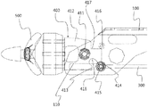
- the tiling part 400 is constituted by a hinge shaft portion 411 , a tilting body portion 412 , a first control portion 413 , a second control portion 414 , a sliding pin portion 415 , a stop pin portion 416 , a stop edge, and a clearance groove 418 .
- FIGS. 5 to 7 specifically illustrate a configuration of the tilting part 400 .
- the hinge shaft portion 411 is provided in a pin shape in which the hinge shaft portion 411 horizontally penetrates the end portion of the body part 100 .
- the hinge shaft portion 411 as a portion which becomes a shaft for rotation of the tilting part 400 penetrates an inner side of the end portion of the body part 100 in a lateral direction vertical to the longitudinal direction of the body part 100 .
- the center of the tilting body portion 412 is penetratively connected to the hinge shaft portion 411 to be rotated around the hinge shaft portion 411 and the other end portion may be connected to the servo part 200 .
- the first control portion 413 is provided in an edge shape at the lower portion of one end portion of the tilting body portion 412 .
- the second control portion 414 is projected on the other end portion of the tilting body portion 412 and provided in the shape of a downward facing edge.
- the clearance groove 418 having a groove inside thereof is provided between the first control portion 413 and the second control portion 414 .
- a stop edge portion 417 having a shape in which an edge is recessed inside thereof is provided at an upper portion of one end portion of the tilting body portion 412 .
- the sliding pin portion 415 is provided in a pin shape which penetrates the sliding hole 110 and provided to apply force to the first control portion 413 and the second control portion 414 while sliding along the sliding hole 110 .
- the stop pin portion 416 is provided in a pin shape which horizontally penetrates the end portion of the body part 100 to control a rotational radius of the tilting part 400 .
- the sliding pin portion 415 is positioned at a rightmost side of the sliding hole 110 , and as a result, the second control portion 414 and the sliding pin portion 415 contact each other.
- the second control portion 414 is supported by the sliding pin portion 415 , and as a result, the tilting part 400 and the rotor part 400 are not rotated.
- the tilting part 400 is rotated as illustrated in FIG. 7 and the sliding pin portion 415 is seated on the clearance groove 418 to persistently rotate the tilting part 400 .
- the sliding pin portion 415 is configured to support the first control portion 413 as illustrated in FIG. 8 to prevent the tilting part 400 from being rotated in an opposite direction.
- the tilting parts 400 positioned at both end portions of the body part 100 are simultaneously rotated by rotation of the rotor part 500 .
- a rotor formed at one end portion of the body part 100 faces upward and a rotor formed at the other end portion of the body part 100 faces downward to generate a thrust for raising an airplane in overall and then, the rotor part 500 is tilted as illustrated in FIG. 10 while the rotation of the rotor part 500 is similarly maintained to generate a thrust for making the airplane head for front.
- a process in which the tilting part 400 is tilted may be repeated optionally (when the airplane rises, when driving, or when landing) according to an operation condition of the airplane.
- the rotor part 500 is provided to generate the thrust and provided to be connected to the tilting part 400 .
- the rotor part 500 may be formed in any form so as to generate an effective thrust.
- the link part 300 is provided to be connected to the servo part 200 to be connected to the tilting part 400 .
Abstract
Description
Claims (4)
Applications Claiming Priority (3)
| Application Number | Priority Date | Filing Date | Title |
|---|---|---|---|
| KR10-2016-0183488 | 2016-12-30 | ||
| KR1020160183488A KR101772224B1 (en) | 2016-12-30 | 2016-12-30 | Tilting type rotor |
| PCT/KR2017/000085 WO2018124353A1 (en) | 2016-12-30 | 2017-01-04 | Tilting rotor |
Publications (2)
| Publication Number | Publication Date |
|---|---|
| US20190337615A1 US20190337615A1 (en) | 2019-11-07 |
| US11220333B2 true US11220333B2 (en) | 2022-01-11 |
Family
ID=59759868
Family Applications (1)
| Application Number | Title | Priority Date | Filing Date |
|---|---|---|---|
| US16/474,356 Active 2037-04-17 US11220333B2 (en) | 2016-12-30 | 2017-01-04 | Tilting type rotor |
Country Status (4)
| Country | Link |
|---|---|
| US (1) | US11220333B2 (en) |
| KR (1) | KR101772224B1 (en) |
| CN (1) | CN110087992A (en) |
| WO (1) | WO2018124353A1 (en) |
Families Citing this family (2)
| Publication number | Priority date | Publication date | Assignee | Title |
|---|---|---|---|---|
| KR102038321B1 (en) * | 2017-12-29 | 2019-10-30 | (주)프리뉴 | Blade assembly having tilt body for drone |
| KR20220074161A (en) * | 2020-11-27 | 2022-06-03 | 현대자동차주식회사 | Propeller tilting apparatus of air mobility |
Citations (11)
| Publication number | Priority date | Publication date | Assignee | Title |
|---|---|---|---|---|
| GB437447A (en) * | 1933-05-23 | 1935-10-28 | Buheiji Fujimoto | Improvements in aeroplanes |
| US6260793B1 (en) | 1999-03-30 | 2001-07-17 | Eurocopter | Convertible aircraft with tilting rotors |
| US6367736B1 (en) | 1999-06-02 | 2002-04-09 | Agusta S.P.A. | Convertiplane |
| US6655631B2 (en) * | 2000-07-28 | 2003-12-02 | John Frederick Austen-Brown | Personal hoverplane with four tiltmotors |
| KR100555176B1 (en) | 2004-12-31 | 2006-03-03 | 한국항공우주연구원 | A tilt-rotor aircraft |
| US20100236021A1 (en) * | 2009-02-05 | 2010-09-23 | Mansfield Assemblies Co. | Appliance hinge counterbalance assembly |
| KR20130077242A (en) | 2011-12-29 | 2013-07-09 | 김성남 | Tilt rotor aircraft |
| US20140034029A1 (en) * | 2012-08-02 | 2014-02-06 | Denso Corporation | Valve apparatus |
| US20160229531A1 (en) | 2014-12-11 | 2016-08-11 | Bell Helicopter Textron Inc. | Convertible tiltrotor aircraft |
| KR101654544B1 (en) | 2016-03-31 | 2016-09-06 | 주식회사 케바드론 | A unmanned aircraft having landing and retention capabilities |
| US20180141655A1 (en) * | 2016-11-23 | 2018-05-24 | Keith Wall | VTOL airplane or drone utilizing at least two tilting propellers located in front of wings center of gravity. |
Family Cites Families (5)
| Publication number | Priority date | Publication date | Assignee | Title |
|---|---|---|---|---|
| KR101554487B1 (en) * | 2013-12-23 | 2015-09-21 | 이상현 | Multi rotor aerial vehicle |
| CN103738820B (en) * | 2014-01-16 | 2015-11-11 | 北京工业大学 | The elevator door latching device that a kind of people of preventing falls |
| CN105035313B (en) * | 2015-06-30 | 2017-03-08 | 北京航空航天大学 | One kind is verted quadrotor |
| CN205293061U (en) * | 2015-11-30 | 2016-06-08 | 湖北易瓦特科技股份有限公司 | Folding assembly |
| CN105620743B (en) * | 2016-02-22 | 2018-02-06 | 南京航空航天大学 | One kind is verted three rotor craft inclining rotary mechanisms |
-
2016
- 2016-12-30 KR KR1020160183488A patent/KR101772224B1/en active IP Right Grant
-
2017
- 2017-01-04 WO PCT/KR2017/000085 patent/WO2018124353A1/en active Application Filing
- 2017-01-04 CN CN201780077656.5A patent/CN110087992A/en not_active Withdrawn
- 2017-01-04 US US16/474,356 patent/US11220333B2/en active Active
Patent Citations (11)
| Publication number | Priority date | Publication date | Assignee | Title |
|---|---|---|---|---|
| GB437447A (en) * | 1933-05-23 | 1935-10-28 | Buheiji Fujimoto | Improvements in aeroplanes |
| US6260793B1 (en) | 1999-03-30 | 2001-07-17 | Eurocopter | Convertible aircraft with tilting rotors |
| US6367736B1 (en) | 1999-06-02 | 2002-04-09 | Agusta S.P.A. | Convertiplane |
| US6655631B2 (en) * | 2000-07-28 | 2003-12-02 | John Frederick Austen-Brown | Personal hoverplane with four tiltmotors |
| KR100555176B1 (en) | 2004-12-31 | 2006-03-03 | 한국항공우주연구원 | A tilt-rotor aircraft |
| US20100236021A1 (en) * | 2009-02-05 | 2010-09-23 | Mansfield Assemblies Co. | Appliance hinge counterbalance assembly |
| KR20130077242A (en) | 2011-12-29 | 2013-07-09 | 김성남 | Tilt rotor aircraft |
| US20140034029A1 (en) * | 2012-08-02 | 2014-02-06 | Denso Corporation | Valve apparatus |
| US20160229531A1 (en) | 2014-12-11 | 2016-08-11 | Bell Helicopter Textron Inc. | Convertible tiltrotor aircraft |
| KR101654544B1 (en) | 2016-03-31 | 2016-09-06 | 주식회사 케바드론 | A unmanned aircraft having landing and retention capabilities |
| US20180141655A1 (en) * | 2016-11-23 | 2018-05-24 | Keith Wall | VTOL airplane or drone utilizing at least two tilting propellers located in front of wings center of gravity. |
Non-Patent Citations (1)
| Title |
|---|
| International Search Report for PCT/KR2017/000085 dated Aug. 31, 2017 from Korean Intellectual Property Office. |
Also Published As
| Publication number | Publication date |
|---|---|
| WO2018124353A1 (en) | 2018-07-05 |
| US20190337615A1 (en) | 2019-11-07 |
| CN110087992A (en) | 2019-08-02 |
| KR101772224B1 (en) | 2017-08-28 |
Similar Documents
| Publication | Publication Date | Title |
|---|---|---|
| EP3335989B1 (en) | Vertical take-off and landing fixed-wing aircraft and the flight control method thereof | |
| US11220333B2 (en) | Tilting type rotor | |
| US11267554B2 (en) | Locking device | |
| JP5497764B2 (en) | Slat support assembly | |
| US9174729B2 (en) | Rotor assembly | |
| US11447258B2 (en) | Motor and unmanned aerial vehicle | |
| JP2013249053A (en) | Slat support assembly | |
| US20180266251A1 (en) | Quick release rotor attachment systems and methods | |
| KR101100401B1 (en) | 2-degree of freedom rotor pitch control system for tilt-rotor aircraft | |
| US20060266880A1 (en) | Servo fixing base structure for remote control helicopers | |
| KR101664899B1 (en) | multicopter | |
| KR102038321B1 (en) | Blade assembly having tilt body for drone | |
| KR20160079182A (en) | Piezo-driven mechanism and Flexure hinge-based piezo-driven fine stage for vertical planar 3-DOF motion with high load capacity having the same | |
| CN105083530A (en) | Aerofoil and aircraft having the same | |
| JP2021070469A (en) | Rotor mount assembly, rotor seat, propulsion system, and unmanned aerial vehicle (uav) | |
| CN105460214A (en) | Vertical take-off and landing tandem wing unmanned aerial vehicle | |
| CN105539818A (en) | Foot stool structure of air vehicle and air vehicle | |
| KR20200000296A (en) | Drone integrated CCTV storage structure | |
| KR101884903B1 (en) | Unmanned aero vehicle | |
| US10322914B2 (en) | Crane socket for a loading crane | |
| BG65742B1 (en) | Lifting device | |
| KR101686161B1 (en) | Multicopter with vehicle function | |
| EP3031719A1 (en) | Lift rotor for a rotorcraft, particularly for a gyroplane | |
| CN106005372A (en) | Four-rotor aircraft and control system thereof | |
| CN217074789U (en) | Drive unit and aircraft comprising same |
Legal Events
| Date | Code | Title | Description |
|---|---|---|---|
| AS | Assignment |
Owner name: SAMCO CO.,LTD, KOREA, REPUBLIC OF Free format text: ASSIGNMENT OF ASSIGNORS INTEREST;ASSIGNORS:MIN, KYOUNGMOO;JANG, SEHOON;NIKESH, BHATTARAI;AND OTHERS;REEL/FRAME:049613/0663 Effective date: 20190612 |
|
| FEPP | Fee payment procedure |
Free format text: ENTITY STATUS SET TO UNDISCOUNTED (ORIGINAL EVENT CODE: BIG.); ENTITY STATUS OF PATENT OWNER: SMALL ENTITY |
|
| FEPP | Fee payment procedure |
Free format text: ENTITY STATUS SET TO SMALL (ORIGINAL EVENT CODE: SMAL); ENTITY STATUS OF PATENT OWNER: SMALL ENTITY |
|
| STPP | Information on status: patent application and granting procedure in general |
Free format text: DOCKETED NEW CASE - READY FOR EXAMINATION |
|
| STPP | Information on status: patent application and granting procedure in general |
Free format text: NON FINAL ACTION MAILED |
|
| STPP | Information on status: patent application and granting procedure in general |
Free format text: RESPONSE TO NON-FINAL OFFICE ACTION ENTERED AND FORWARDED TO EXAMINER |
|
| STPP | Information on status: patent application and granting procedure in general |
Free format text: FINAL REJECTION MAILED |
|
| STPP | Information on status: patent application and granting procedure in general |
Free format text: RESPONSE AFTER FINAL ACTION FORWARDED TO EXAMINER |
|
| STPP | Information on status: patent application and granting procedure in general |
Free format text: NOTICE OF ALLOWANCE MAILED -- APPLICATION RECEIVED IN OFFICE OF PUBLICATIONS |
|
| STPP | Information on status: patent application and granting procedure in general |
Free format text: PUBLICATIONS -- ISSUE FEE PAYMENT RECEIVED |
|
| STPP | Information on status: patent application and granting procedure in general |
Free format text: PUBLICATIONS -- ISSUE FEE PAYMENT VERIFIED |
|
| STCF | Information on status: patent grant |
Free format text: PATENTED CASE |