JP5497764B2 - Slat support assembly - Google Patents
Slat support assembly Download PDFInfo
- Publication number
- JP5497764B2 JP5497764B2 JP2011525618A JP2011525618A JP5497764B2 JP 5497764 B2 JP5497764 B2 JP 5497764B2 JP 2011525618 A JP2011525618 A JP 2011525618A JP 2011525618 A JP2011525618 A JP 2011525618A JP 5497764 B2 JP5497764 B2 JP 5497764B2
- Authority
- JP
- Japan
- Prior art keywords
- slat
- slat support
- bearing surface
- bearing
- support arm
- Prior art date
- Legal status (The legal status is an assumption and is not a legal conclusion. Google has not performed a legal analysis and makes no representation as to the accuracy of the status listed.)
- Expired - Fee Related
Links
Images


Classifications
-
- B—PERFORMING OPERATIONS; TRANSPORTING
- B64—AIRCRAFT; AVIATION; COSMONAUTICS
- B64C—AEROPLANES; HELICOPTERS
- B64C9/00—Adjustable control surfaces or members, e.g. rudders
- B64C9/14—Adjustable control surfaces or members, e.g. rudders forming slots
- B64C9/22—Adjustable control surfaces or members, e.g. rudders forming slots at the front of the wing
-
- B—PERFORMING OPERATIONS; TRANSPORTING
- B64—AIRCRAFT; AVIATION; COSMONAUTICS
- B64C—AEROPLANES; HELICOPTERS
- B64C9/00—Adjustable control surfaces or members, e.g. rudders
- B64C9/02—Mounting or supporting thereof
-
- Y—GENERAL TAGGING OF NEW TECHNOLOGICAL DEVELOPMENTS; GENERAL TAGGING OF CROSS-SECTIONAL TECHNOLOGIES SPANNING OVER SEVERAL SECTIONS OF THE IPC; TECHNICAL SUBJECTS COVERED BY FORMER USPC CROSS-REFERENCE ART COLLECTIONS [XRACs] AND DIGESTS
- Y02—TECHNOLOGIES OR APPLICATIONS FOR MITIGATION OR ADAPTATION AGAINST CLIMATE CHANGE
- Y02T—CLIMATE CHANGE MITIGATION TECHNOLOGIES RELATED TO TRANSPORTATION
- Y02T50/00—Aeronautics or air transport
- Y02T50/40—Weight reduction
Description
初めに
本発明は航空機翼の前縁上でスラットを支持するための支持アセンブリに関する。本発明はさらに、本発明の支持アセンブリを用いて、翼の前縁に取付けられる少なくとも1つのスラットを含む航空機翼に関する。
Introduction The present invention relates to a support assembly for supporting a slat on the leading edge of an aircraft wing. The present invention further relates to an aircraft wing including at least one slat attached to the leading edge of the wing using the support assembly of the present invention.
背景
航空機は、離陸、着陸および飛行のために、さまざまなレベルの揚力を生成する必要がある。翼の前縁および後縁装置の組合せを用いて、翼の揚力係数を制御する。前縁装置はスラットとして知られている。大型の航空機では、複数のスラットが翼のエッジに沿って間隔が空けられて配置されている。通常の飛行の際、スラットは翼の前縁に対して引っ込んでいる。しかし、離陸および着陸の際には、スラットは翼の面を横切るまた下を通る気流を変動させるために、翼の前方に配備される。スラットは一般にその収容位置および配備位置間でアーチ状または湾曲した経路を辿る。スラットが前記経路に沿って配備される程度を変えることにより、翼によって与えられる揚力を制御することができる。
Background Aircraft need to generate varying levels of lift for takeoff, landing and flight. A combination of wing leading and trailing edge devices is used to control the lift coefficient of the wing. The leading edge device is known as a slat. In large aircraft, multiple slats are spaced along the wing edge. During normal flight, the slat is retracted against the leading edge of the wing. However, during take-off and landing, slats are deployed in front of the wings to fluctuate the airflow across and under the wings. A slat generally follows an arcuate or curved path between its stowed and deployed positions. By varying the degree to which the slats are deployed along the path, the lift provided by the wings can be controlled.
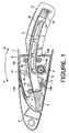
スラットをその収容位置と配備位置との間で支持および案内するためのアセンブリが必要であり、翼1の一部および収容位置にあるスラット2の典型的な配置が図1に示される。図1からわかるように、スラット2にはアーチ状の支持アームまたはスラットトラック3が設けられ、その一方端4はスラット2の後に固く取付けられて、翼1内に延在する。スラットトラック3は翼構造を形成する機械加工されたリブ5および翼桁6を貫通する。スラットトラック3は、ある軸を有する円弧を規定し、スラットトラック3の一方端に取付けられるスラット2を配備および引っ込むよう、軸を中心として回転(図1においてAおよびBの矢印によって示される方向)できるよう翼内に取付けられる。
An assembly is required to support and guide the slat between its stowed and deployed positions, and a typical arrangement of a portion of the
スラット2を配備または引っ込むようスラットラック3を駆動するために、歯付きスラットラック7であってスラットトラック3のアーチ形状に対応するアーチ形状を有するスラットラック7が、スラットトラック3上の凹所3a内に取付けられ、さらに対応する歯付きドライブピニオン8がスラットラック7上で歯7aと係合し、ドライブピニオン8が回転すると、ドライブピニオン8の歯8aおよびラック7の歯7aが協働して、スラットラック7およびそこに取付けられるスラットを、配備位置に、すなわち図1の矢印Aの方向に、回動または駆動させる。典型的に、スラットトラック3は完全に収容された位置と完全に配備された位置との間で27度の角度で回転する。ピニオン8を反対方向に回転させると、スラットトラック3は矢印Bの方向に、図1に示されるように収容位置に戻る。
To drive the slat rack 3 to deploy or retract the slat 2, the slat rack 7, which has a toothed slat rack 7 and has an arch shape corresponding to the arch shape of the slat track 3, has a
ドライブピニオン8は、翼1の前縁に沿ってかつその中に延在するシャフト9に取付けられる。複数のギヤ8をシャフト8に回転可能に取付けることができ、その1つは各スラット2を駆動させ、シャフト9が翼1の機体側近くにあるスラット配備モータによって回転させられると、すべてのスラットは一緒に配備される。
The
スラットトラック3は略正方形の断面外形を有し、上表面3bおよび下表面3cの各々はシリンダの湾曲面の一部を規定し、各々の軸はスラットトラック3の回転軸と同軸である。 The slat track 3 has a substantially square cross-sectional outline, and each of the upper surface 3b and the lower surface 3c defines a part of the curved surface of the cylinder, and each axis is coaxial with the rotational axis of the slat track 3.
スラットトラック3は、スラットトラック3の上下にあるローラベアリング10aおよび10b間に支持され、各ベアリング10aおよび10bの回転軸は、他方のベアリング10aおよび10bの回転軸に対して、かつスラットトラック3が収容位置と配備位置との間でAおよびBの矢印方向に回転する軸に対して、平行である。上ベアリング10aはスラットトラック3の上表面3bと接触し、下ベアリング10bは下表面3cと接触して、両方が配備および引っ込み位置の際にスラットトラック3を支持、案内する。ベアリング10aおよび10bは飛行の際、収容および配備位置で、スラット2に与えられる縦負荷に対抗し、スラットの配備および引っ込みの際に、スラットトラック2の移動を案内する。
The slat track 3 is supported between
ベアリング10aおよび10bは縦方向に与えられる負荷だけに対抗する。縦負荷とは、図面の紙面に延在する方向に働く負荷、または各ベアリングの回転軸に対して直角に働く方向の負荷を意味する。
The
飛行の際縦方向に作用する負荷に加えて、著しい側面負荷がスラット2に作用するが、これはスラット2が気流方向に対して正確に直交して翼1の前縁に延在しないからである。側面負荷とは、図面の紙面に延在する方向以外の方向に働く負荷、すなわち、各ベアリング10aおよび10bの回転軸に対して直角以外の方向に働く負荷を意味する。
In addition to the loads acting in the longitudinal direction during flight, significant side loads act on the slats 2 because the slats 2 do not extend at the leading edge of the
側面負荷に対抗するために、スラットトラック3は上下に取付けられている縦負荷ベアリング10に対して、スラットトラック3の両側に配置されるさらなるベアリング11によっても支持される。これら側面負荷ベアリング11は回転しなくてもよく、単にベアリング面、パッドまたはクッションを含み、側面負荷がスラット2に与えられる場合に、スラットトラック3の側壁が当る。
In order to counter lateral loads, the slat track 3 is also supported by
さらに、一般に「ファンクピン」と呼ばれる少なくとも1つのフェールセーフシャフト12が各上ベアリング10a間に設けられ、縦負荷ベアリング10が損なわれた場合に、スラットトラック3を支持するよう位置付けられている。ファンクピン12は非回転可能なシャフトであってもよく、ベアリング10が損なわれた場合に、その上をスラットトラック3が摺動または滑る。通常の動作では、ファンクピンは何の働きもせず、各ピンとスラットトラック3の表面との間に間隙があり、スラットトラック3はベアリングが損なわれた場合を除き、ファンクピンとは接触しない。
In addition, at least one failsafe shaft 12, commonly referred to as a “funk pin”, is provided between each
翼1の前縁近くの、翼構造内のコンポーネント用スペースは、特にスラットトラック3がその上下ベアリング10aおよび10bならびに横ベアリング11や、ドライブピニオン8およびピン12とともにすべて設置されると、非常に制限されている。これらすべてのコンポーネントを収容する要件は、重量、製造コストおよび複雑性を増加させるのに加えて、翼1の形に設計上の制限を与える。
The space for components in the wing structure near the leading edge of the
さらなる側面負荷ベアリング11およびファンクピン12は、各上ベアリング10aや下ベアリング10b間に配置されるので、これらのベアリングはスラットトラック3の軸を中心として円周方向に互いに間隔が空けられていなければならず、その間の距離は、側面負荷ベアリング10aおよび10bならびにファンクピン12を受入れるよう、ベアリング10aおよび10b間に十分なスペースを与えるものでなければならない。その結果、従来のアセンブリのさらなる不利点は、スラット2に対して所望の最大配備角度を受入れるのに相対的に長くならなければならないとともに、スラットトラック3が最大配備位置においても、スラットトラック3上の2つの縦負荷ベアリング10aおよびスラットトラック3下の2つの縦負荷ベアリング10bによって、適切に支持されなければならないことである。その長い長さの結果、スラットトラック3は桁6を貫通し、スラットトラック3の自由端は、桁6の後にあって翼1内に収容されている燃料からスラットトラック3を分離しているトラックカン13内に受入れられなければならない。しかし、翼構造体を弱くするので、桁6内に開口を有することは望ましくない。さらに、トラックカン13の要件はさらなる問題および組立事項をもたらし、燃料の漏れを防ぐために、トラックカン13が桁6に接続される箇所では適切な封止を設ける必要がある。
Further
本発明の実施例は、上記の問題を解消または実質的に軽減する航空機スラット支持アセンブリを提供することに向けられている。 Embodiments of the present invention are directed to providing an aircraft slat support assembly that eliminates or substantially mitigates the above problems.
発明の概要
本発明に従い、スラット支持アセンブリが提供され、長さに沿って延在する複数のベアリング面を有するスラット支持アームを備え、スラット支持アームは前記スラット支持アームの一方端に取付けられるスラットを、航空機翼の前縁から配備するよう移動可能であり、さらに翼内に取付け可能な複数のベアリングを備え、各ベアリングは関連するベアリング面と転がり接触して、スラットの配備および引っ込みの際にスラット支持アームを支持および案内し、ベアリング面および関連するベアリングの少なくとも一部は、各ベアリングが2つ以上の方向でスラット支持アームに与えられる負荷に対抗するよう構成されている。
SUMMARY OF THE INVENTION In accordance with the present invention, a slat support assembly is provided and includes a slat support arm having a plurality of bearing surfaces extending along a length, the slat support arm comprising a slat attached to one end of the slat support arm. A plurality of bearings that are movable for deployment from the leading edge of an aircraft wing and that can be mounted within the wing, each bearing in rolling contact with an associated bearing surface to allow slats to be deployed and retracted Supporting and guiding the support arms, at least a portion of the bearing surfaces and associated bearings are configured to resist the load applied to the slat support arms in each of two or more directions.
各ベアリングは、複数の方向からスラット支持アームに与えられる負荷に耐えることができるので、さらなる側面負荷ベアリングやクッションは不要となり、必要なコンポーネントの数およびアセンブリの重量を減少させる。コンポーネントの減少により、翼の前縁内の空間が増えることになり、ベアリングは配備方向においてより近く位置付けることが可能となり、それにより通常の場合よりも短いスラット支持アームを用いることができるようになる。 Each bearing can withstand loads applied to the slat support arm from multiple directions, eliminating the need for additional side load bearings or cushions, reducing the number of components required and the weight of the assembly. The reduction in components will increase the space in the leading edge of the wing, allowing the bearings to be positioned closer in the deployment direction, thereby allowing shorter slat support arms to be used than usual. .
ある好ましい実施例において、スラット支持アームは1対の隣接する上ベアリング面を有し、ある上ベアリング面に関連するベアリングが他方の上ベアリング面に関連するベアリングと共通の軸を共有しないよう、各上ベアリング面は隣接する上ベアリング面に対してある角度で配置される。 In a preferred embodiment, the slat support arm has a pair of adjacent upper bearing surfaces, and each bearing associated with one upper bearing surface does not share a common axis with the bearing associated with the other upper bearing surface. The upper bearing surface is disposed at an angle with respect to the adjacent upper bearing surface.
各ベアリングの回転軸は互いに直角に交差することができるが、各ベアリングの回転軸は90度より小さいまたは大きい角度で交差できることも想定される。 The rotational axes of each bearing can intersect at right angles to each other, but it is also envisioned that the rotational axes of each bearing can intersect at an angle of less than or greater than 90 degrees.
一実施例において、スラット支持アームは1対の隣接する下ベアリング面を有し、各下ベアリング面は、一方の下ベアリング面に関連するベアリングの回転軸が、他方の下ベアリング面に関連するベアリングの回転軸と同軸であるよう、配置される。 In one embodiment, the slat support arm has a pair of adjacent lower bearing surfaces, each lower bearing surface having a bearing axis associated with one lower bearing surface and a bearing associated with the other lower bearing surface. It is arrange | positioned so that it may be coaxial with the rotating shaft.
別の実施例において、スラット支持アームは第2の下隣接ベアリング面の対を有し、前記第2の対の各ベアリング面は、一方の下ベアリング面に関連するベアリングが隣接する下ベアリング面に関連するベアリングと共通の軸を共有しないよう、隣接する下ベアリング面に対してある角度で配置される。 In another embodiment, the slat support arm has a second lower adjacent bearing surface pair, each bearing surface of the second pair being adjacent to the lower bearing surface adjacent to the bearing associated with one lower bearing surface. It is arranged at an angle with respect to the adjacent lower bearing surface so as not to share a common axis with the associated bearing.
前記他の実施例において、各下ベアリング面に関連する各ベアリングの回転軸は、互いに直角に交差し得るが、他の角度も想定される。 In said other embodiment, the axis of rotation of each bearing associated with each lower bearing surface can intersect at right angles to each other, although other angles are envisioned.
別の実施例において、スラット支持アームは、湾曲しており、湾曲軸に対応する軸を中心として回転可能であり、少なくとも上ベアリング面は軸方向に延在する幅を有し、スラット支持アームの軸から各上ベアリング面までの半径方向の距離は、各上ベアリング面の幅にわたって変化する。 In another embodiment, the slat support arm is curved and rotatable about an axis corresponding to the curved axis, at least the upper bearing surface has an axially extending width, The radial distance from the shaft to each upper bearing surface varies across the width of each upper bearing surface.
軸からベアリング面までの半径方向の距離が、ベアリング面の幅にわたって変化するので、ベアリング面と転がり接触しているベアリングは、側面負荷および縦負荷を含む、すべての方向の負荷に耐えることができる。半径方向の距離とは、スラット支持アームの軸からベアリング面への最も短い距離、すなわちスラット支持アームの軸からベアリング面まで垂直に延在する線の長さを意味する。 Because the radial distance from the shaft to the bearing surface varies across the width of the bearing surface, a bearing in rolling contact with the bearing surface can withstand loads in all directions, including side loads and longitudinal loads. . By radial distance is meant the shortest distance from the axis of the slat support arm to the bearing surface, ie the length of the line extending perpendicularly from the axis of the slat support arm to the bearing surface.
典型的には、半径方向の距離は、ベアリング面の幅をわたる方向において線形に変化する。 Typically, the radial distance varies linearly in the direction across the bearing surface width.
好ましい実施例において、ベアリング面は1対の上ベアリング面を含む。
最も好ましくは、スラット支持アームの軸から一方の上ベアリング面までの半径方向の距離は、その幅にわたる方向において増加し、スラット支持アームの軸から他方の上ベアリング面までの距離は、その幅にわたって同じ方向に減少する。
In a preferred embodiment, the bearing surface includes a pair of upper bearing surfaces.
Most preferably, the radial distance from the axis of the slat support arm to one upper bearing surface increases in a direction across its width, and the distance from the axis of the slat support arm to the other upper bearing surface extends across its width. Decrease in the same direction.
一実施例において、各上ベアリング面は軸方向に延在する幅を有する領域によって分けられ、軸から前記領域までの距離は、その幅にわたる方向において一定である。 In one embodiment, each upper bearing surface is divided by a region having a width extending in the axial direction, and the distance from the shaft to the region is constant in the direction across that width.
好ましい実施例において、ベアリング面はさらに1対の下ベアリング面を含む。
好ましくは、下ベアリング面の各々は、軸方向に延在する幅を有し、軸から各前記下ベアリング面までの半径方向の距離は、各下ベアリング面の幅にわたる方向において一定である。
In a preferred embodiment, the bearing surface further includes a pair of lower bearing surfaces.
Preferably, each of the lower bearing surfaces has a width extending in the axial direction, and the radial distance from the shaft to each said lower bearing surface is constant in the direction across the width of each lower bearing surface.
スラット支持アームの軸から一方の下ベアリング面までの距離は、その幅をわたる方向において増加し、軸から他方の下ベアリング面までの距離は、その幅にわたって同じ方向において減少する。 The distance from the axis of the slat support arm to one lower bearing surface increases in the direction across its width, and the distance from the axis to the other lower bearing surface decreases in the same direction across its width.
好都合に、各下ベアリング面は軸方向に延在する幅を有する領域によって分離されてもよく、軸から前記領域までの半径方向の距離は、各下ベアリング面の幅をわたる方向において一定である。 Advantageously, each lower bearing surface may be separated by a region having a width extending in the axial direction, and the radial distance from the shaft to said region is constant in the direction across the width of each lower bearing surface. .
好ましい実施例において、各上ベアリング面は半径方向において下ベアリング面と離れている。 In the preferred embodiment, each upper bearing surface is radially spaced from the lower bearing surface.
スラット支持アームの軸から一方のベアリング面までの半径方向の距離は、その幅にわたる方向において増加し、軸から他方のベアリング面までの距離は、その幅をわたる同じ方向に減少してもよい。 The radial distance from the axis of the slat support arm to one bearing surface may increase in the direction across its width, and the distance from the axis to the other bearing surface may decrease in the same direction across its width.
典型的に、少なくとも1つのベアリングは各ベアリング面と転がり接触している。理想的には、2個または3個のベアリングが各面と転がり接触する。 Typically, at least one bearing is in rolling contact with each bearing surface. Ideally, two or three bearings are in rolling contact with each surface.
好ましい実施例において、各ベアリングの回転軸はそのベアリングが接触しているベアリング面に対して平行であるが、ベアリングの回転軸はスラット支持アームの軸に対して平行であることも想定され、その場合、ベアリングの面は対応するベアリング面に対して転がり接触するよう角度付けられている。 In the preferred embodiment, the axis of rotation of each bearing is parallel to the bearing surface that the bearing is in contact with, but it is also envisioned that the axis of rotation of the bearing is parallel to the axis of the slat support arm, In some cases, the bearing surface is angled to make rolling contact with the corresponding bearing surface.
ベアリングは有利にベアリングヨークに取付けられ、ヨークは航空機の翼構造に取付けるよう構成されている。 The bearing is preferably mounted on a bearing yoke, which is configured to be mounted on an aircraft wing structure.
ベアリングヨークは好ましくはスラット支持アームを受入れる穴を有するフレームと、ベアリング面と転がり接触するよう、ベアリングをヨークに取付ける手段とを備える。 The bearing yoke preferably comprises a frame having a hole for receiving a slat support arm and means for attaching the bearing to the yoke for rolling contact with the bearing surface.
一実施例において、各ベアリングは一方端にキャップを有するシャフトに回転可能に取付けられてもよい。キャップと離れた、シャフトの他方端は螺刻されて、ヨーク内の対応する螺刻された穴と係合でき、ヨークは、シャフトの前記螺刻された端部がヨークの螺刻された穴と係合した場合に、キャップを受入れて支持する開口を有する。 In one embodiment, each bearing may be rotatably mounted on a shaft having a cap at one end. Apart from the cap, the other end of the shaft is threaded to engage with a corresponding threaded hole in the yoke, the yoke being threaded in the yoke at the threaded end of the shaft And an opening for receiving and supporting the cap when engaged.
一実施例において、汚れがキャップとヨークとの間からベアリング内に入るのを防ぐために、キャップとヨークとの間はOリングシールによって封止を形成することができる。 In one embodiment, a seal can be formed between the cap and yoke by an O-ring seal to prevent dirt from entering the bearing from between the cap and yoke.
好都合に、ツール係合手段がキャップ上に設けられて、シャフトの螺刻された部分をヨークに結合するよう、シャフトを回転させることができる。 Conveniently, tool engagement means may be provided on the cap to rotate the shaft to couple the threaded portion of the shaft to the yoke.
一実施例において、複数のヨークはスラット支持アームの軸を中心としてある角度で互いに離れており、各ヨークは1対の上ベアリングおよび1対の下ベアリングを収納する。 In one embodiment, the plurality of yokes are spaced from each other at an angle about the axis of the slat support arm, and each yoke houses a pair of upper bearings and a pair of lower bearings.
一実施例において、スラットから離れているスラット支持アームの自由端は面取りされている。 In one embodiment, the free end of the slat support arm remote from the slat is chamfered.
スラット支持アセンブリは好ましくはスラット支持アームに溝と、溝内においてスラット支持アームに取付けられるスラットラックとを含み、スラットの配備および引っ込みのために、軸を中心としてスラットトラックを回転させるよう構成されているドライブピニオンと協働する。 The slat support assembly preferably includes a groove in the slat support arm and a slat rack attached to the slat support arm in the groove and is configured to rotate the slat track about an axis for deployment and retraction of the slat. Work with the drive pinion.
本発明の別の局面に従い、航空機翼が設けられ、航空機翼はスラットと、本発明によるスラット支持アセンブリとを有し、スラット支持アームはスラットが完全に配備された位置に達すると、翼の前縁から最も離れているヨークを外すよう構成されている。 In accordance with another aspect of the present invention, an aircraft wing is provided, the aircraft wing having a slat and a slat support assembly according to the present invention, wherein the slat support arm is in front of the wing when the slat reaches a fully deployed position. The yoke farthest from the edge is configured to be removed.
本発明の実施例は、例示によって、添付されている図2から図7を参照して説明される。 Embodiments of the present invention will now be described by way of example with reference to the accompanying FIGS.
好ましい実施例の説明
図1は、翼の前縁およびスラットの一部を示す先行技術の図であり、既に説明されている。
DESCRIPTION OF PREFERRED EMBODIMENTS FIG. 1 is a prior art diagram showing the leading edge of a wing and a portion of a slat, which has already been described.
図2および図3を参照すると、本発明の一実施例に従い、スラットトラック支持アセンブリ20の簡略断面が示される。この断面は,前から見た湾曲したスラット支持アームまたはスラットトラック21を通ったものである、すなわち翼の前縁に向かって見た方向から取られており、スラット支持アーム21の前端部に取付けられるスラット自体はこれらの図面では見えず、スラット支持アーム21に取付けられるスラット2が配備された場合に、スラット支持アーム21は紙面から見る側に向かう方向において、その理論的中心または軸(図面には示されていない)を中心として回転する。
2 and 3, a simplified cross section of a slat
図1の先行技術の図に見られるように、湾曲したスラット支持アーム21はその長さに沿ってアーチ状の溝または凹所22を有し、その中にスラット支持アーム21に取付けられるスラットラック23が受入れられる。スラットラック23は下側の露出面に沿って延在している歯23aを有し、ドライブピニオン(図示されていないが、図1に示されるドライブピニオン8と類似)と係合し、従来通りスラット配備位置とスラット引っ込み位置との間でスラット支持アーム21を駆動する。
As can be seen in the prior art diagram of FIG. 1, the curved
スラット支持アーム21は、航空機翼の構造体の一部をなす2つのリブ24間に形成される空間内に延在し、上ベアリングヨーク25はリブ24に対して固く取付けられ、その間に延在する。シャフト26もスラット支持アーム21下で、リブ24に固く取付けられてその間に延在する。2つのベアリング27a,27bはシャフト26上に回転可能に取付けられ、スラット支持アーム21上の対応するベアリング面28a,28bと転がり接触する。ベアリング27a,27bおよび対応するベアリング面28a,28bの回転軸(A−A,図2参照)は、配備位置と引っ込み位置との間で移動する際、スラット支持アーム21の回転軸(X−X)と平行である。これらのベアリングは縦方向、すなわち図2の矢印F方向にスラット支持アーム21に与えられる負荷のみに対抗し、スラット支持アーム21の側面負荷を支持することはできない。しかし、スラット支持アーム21の上側は2つのベアリング面29a,29bに分割され、各々はある角度でスラット支持アーム21の側面から先端30に向かって上方向に延在する。それにより、スラット支持アーム21の上端縁の断面は三角形の外形を有するが、ベアリング面29a,29bはその先端で合致する必要はないことも想定され、スラット支持アーム21の軸に対して平行に延在する2つのベアリング面間に領域があってもよい。
The
1対の上ベアリング31a,31bは別々の角度の付けられたシャフト32a,32bに回転可能に取付けられ、上ベアリングヨーク25内に受入れられ、ベアリング31aは角度の付いたベアリング面29aと転がり接触し、ベアリング31bは角度の付いたベアリング面29bと転がり接触する。シャフト32a,32bは、各ベアリング31a,31bの回転軸(B−BおよびC−C)が対応するベアリング面29a,29bと平行であるよう角度が付けられている。ベアリング31a,31bと対応するベアリング面29a,29bとの間の接触面がスラット支持アーム21の回転軸と平行でないよう上ベアリング31a,31bを配向した結果、上ベアリング31a,31bは、縦負荷に加えて、スラット支持アーム21に与えられる側面負荷の力、すなわち図2の矢印L方向に与えられる力、に対抗することができるようになる。したがって、先行技術のスラット支持アセンブリで従来用いられていた付加的側面負荷ベアリングは不要となり、重量を減少させ、スペースおよびコストを節約することとなる。
A pair of
ベアリング面29a,29bはスラット支持アームの回転軸に平行ではないので、スラット支持アームの軸X−Xからの半径方向の距離は、図2に示されるように、最大距離D1および最小距離D2間で、軸に沿った方向において変わる。半径方向の距離については、左側のベアリング面29aに対しては第1の方向(図2に示されるように右から左)に半径方向の距離が減少し、右側のベアリング面29bに対して第2の方向(図2に示されるように、左から右)に半径方向の距離が減少する。
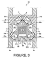
図3は図2に示される配置と同様の配置を示すが、下ベアリング27a,27bは上ベアリング31a,31bと同じ態様で配置され(別個の軸A1−A1およびA2−A2を有する)、スラット支持アーム21の下ベアリング面28a,28bもスラット支持アーム21の回転軸に対して角度が付けられている。下ベアリング27a,27bの各々は、航空機翼のリブ24間に延在する下ヨーク33内に受入れられる個々のシャフト32a,32bに回転可能に取付けられる。本実施例において、下ベアリング27a,27bおよび上ベアリング31aおよび31bは、スラット支持アーム21に与えられる側面および縦の負荷両方に対抗することができる。
FIG. 3 shows an arrangement similar to that shown in FIG. 2, but the
下ベアリング面28a,28bおよび/または上ベアリング面29a,29bは、スラット支持アーム21が回転する軸に対して45度の角度が付けられているが、ベアリング面28a,28b;29a,29bは、ベアリングが耐えなければならない負荷に応じて、0から90度間のどの角度をも有することができる。たとえば、側面負荷力は縦負荷力よりも実質的に小さいので、ベアリング面は関連するベアリングが側面負荷力より大きい縦負荷力に対抗する位置にあるよう、角度が付けられる。
The
図2に示される配置の一般化された側面は図4に示され、そこではスラット2は翼1の前縁に対して上に載っている引っ込み位置を取る。本実施例において、3つの上ヨーク25があり、スラット支持アーム21上に、スラット支持アーム21の理論的回転中心または回転軸Xを中心としたある角度で離れて配置されており、各ヨークは図2を参照して説明されたように、2つのベアリング31a,31bを受入れる。さらに3つの下ベアリング27aが示され、スラット支持アーム21の回転軸Xを中心として互いにある角度で離れており、上側の組のベアリング31a,31bの各々に対応する。スラットラック23上の歯23aと係合するドライブピニオン33も下ベアリング27aのうちの2つの間に配置されて示されており、スラット支持アーム21をその配備および引っ込み位置間で駆動させる。
A generalized side view of the arrangement shown in FIG. 2 is shown in FIG. 4 where the slat 2 assumes a retracted position resting on the leading edge of the
同様の一般的な側面が図5に示されているが、図5では、スラット2は最大配備位置で示される。この位置に達するためには、スラット支持アーム21は約24度(図4および図5において角度αによって示される)の角度で軸Xを中心として回転している。この位置において、ベアリング27a,27b;31a,31bの後縁の組、すなわち、翼の前縁またはスラット2から最も遠いベアリングは、冗長である。なぜなら、スラット支持アーム21はこれらのベアリングとは係合せず、翼1の前縁により近い残りの2組のベアリングによって完全に支持されているからである。この後縁の組のベアリングを完全に省くことができると想定されるが、スラット2が引っ込んだ場合に、飛行の際のスラットへのさらなる支持を提供するために、後縁の組のベアリングを設けることは有利であり得る。スラット支持アーム21が引っ込んだ場合に、スラット支持アーム21の自由端を後縁の組のベアリングと係合するよう案内するためには、スラット支持アーム21の自由端はわずかに面取りされるまたは斜角面35を有してもよい。
A similar general aspect is shown in FIG. 5, but in FIG. 5, the slat 2 is shown in the maximum deployed position. To reach this position, the
縦負荷ベアリング間にさらなる側面負荷ベアリングを設ける必要はなくなったので、ベアリングの組は互いにより近く配置することができ、それにより翼構造内での空間を節約し、スラット支持アーム21の長さを減少させることができるようになる。なぜなら、スラット支持アーム21はスラット2が完全に配備された場合でも、2つのベアリングの組によって支持されるからである。スラット支持アーム21の長さの減少により、桁6を貫通する必要はなく、トラックカンも不要となる。さらなる利点として、スラット支持アーム21の理論的回転中心または回転軸から延在する線が上および下ベアリングの両方の軸を通って延在するよう、対応の上ベアリングおよび下ベアリングを配置することが可能となる。なぜなら、ベアリングはスラット支持アームの理論的回転中心を通る実際の半径方向における中央線上に配置することができ、それにより、負荷受入れ機能を向上させるからである。先行技術の構成ではこれは可能ではない。なぜなら、縦負荷ベアリング間にさらなる側面負荷ベアリングを設けるための空間および要件があるからである。
Since it is no longer necessary to provide additional side load bearings between the longitudinal load bearings, the bearing sets can be placed closer together, thereby saving space in the wing structure and reducing the length of the
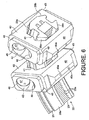
図6および図7を参照すると、図3の一般化された実施例のより実用的な構成が示され、スラット支持アーム21は上ベアリング面29a,29bおよび下ベアリング面28a,28bを有する。スラットラック23は溝22内に受入れられ、ドライブピニオン(図示されていない)と係合するための歯23aを有する。
Referring to FIGS. 6 and 7, a more practical configuration of the generalized embodiment of FIG. 3 is shown, wherein the
各組のベアリング27a,27b;31a,31bは単一のヨーク40内に取付けられ、ヨーク40は中にスラット支持アーム21を受入れるよう形作られている開口41を有する。ヨーク41は端部面43に凹所42を有し、ベアリング27a,27b;31a,31bの挿入および取外しを容易にする。これは図7においてさらにはっきりとわかり、図6と同様であるが、明瞭にするためにヨーク40が省略されている。各ベアリング27a,27b;31a,31bはベアリング要素43(図7参照)を含み、これはシャフト44上に回転可能に取付けられている。シャフト44は端部キャップまたは頭部45を有し、キャップ45から遠いシャフト44の端部は、46において一部が螺刻されて、シャフト44が取付けられるベアリング要素43とともにヨーク40の端部面の穴42を通って挿入された場合に、ヨーク40の対応する螺刻された穴(図示されていない)と捩じ切りされた係合をなす。キャップ45はヨーク内の凹所42の中で支持され、汚れの侵入を防ぐために、キャップ45と凹所42の壁との間のギャップを封止するための封止要素が設けられてもよい。キャップ45の上面47に穴48を設けて、中に挿入されるツールと係合してヨーク40に取付けることができる。ヨーク40は水をヨーク40から出すための排出穴40aが設けられてもよい。
Each set of
ヨーク40の端面43にショルダ49が設けられる。その形状は、各ヨーク40が内部に取付けられるベアリング27a,27b,31a,31bとともに、組立の際に航空機翼1に挿入できるようにすることが想定され、ショルダ49は対応するリブ5間で係合し、スラット支持アーム21を受入れるよう正しい位置にそれぞれのヨーク40を位置付ける。
A
本発明の実施例は、従来のスラット支持アセンブリで必要なベアリングの数を50%まで減らすことができる。なぜなら、側面負荷は縦負荷に対抗するベアリングと同じベアリングによって対抗するようになるので、別の側面負荷ベアリングを設ける必要がなくなったからである。これにより、重量を著しく減少させることができ、および/または翼の密度が高い前縁内での設計上の空間の制約を大きく減少させる。 Embodiments of the present invention can reduce the number of bearings required in a conventional slat support assembly by 50%. This is because the side load is countered by the same bearing as the bearing that counteracts the longitudinal load, so that it is not necessary to provide another side load bearing. This can significantly reduce weight and / or greatly reduce the design space constraints within the leading edge where the wing density is high.
上記の説明は一例であって、請求の範囲から逸脱することなく本発明のスラット支持アセンブリに変形を行なうことができる。たとえば、本発明の上記の実施例では、スラット支持アームはその収容位置および配備位置間では、軸を中心として湾曲しており、前記軸を中心として回転する。しかし、スラット支持アームは楕円形または線形の経路のような、円形ではない経路を辿ることができ、および/またはスラット支持アームは湾曲していないことも想定される。 The above description is exemplary and modifications may be made to the slat support assembly of the present invention without departing from the scope of the claims. For example, in the above-described embodiment of the present invention, the slat support arm is curved about the axis between the storage position and the deployed position, and rotates about the axis. However, it is also envisioned that the slat support arm can follow a non-circular path, such as an elliptical or linear path, and / or the slat support arm is not curved.
Claims (15)
長さに沿って延在する複数のベアリング面(28a,28b,29a,29b)を有するスラット支持アーム(21)を備え、スラット支持アーム(21)は一つの軸(X)の周りに湾曲していて前記スラット支持アーム(21)の一方端に取付けられるスラットを航空機翼の前縁から配備するよう前記軸(X)の周りで回転可能であり、
翼内において取付け可能である複数の上側と下側の円筒ローラベアリング(27a,27b,31a,31b)を備え、各ベアリング(27a,27b,31a,31b)は関連するベアリング面(28a,28b,29a,29b)と転がり接触し、スラットの配備および引っ込みの際にスラット支持アーム(21)を支持および案内し、各ベアリングの回転軸は、ベアリング面と平行であり、
スラット支持アセンブリは1対の隣接する上ベアリング面を有し、各上ベアリング面(29a,29b)と関連するベアリング(31a,31b)が共通の軸を共有しないよう、各上ベアリング面(29a,29b)は隣接する上ベアリング面(29a,29b)に対してある角度で配置され、
前記上側と下側の円筒ローラベアリング(27a,27b,31a,31b)はベアリングヨーク(40)内に装着されており、このヨーク(40)は航空機の翼構造に取付けられるように構成されており、前記アセンブリはヨーク(40)の複数個を含み、各ヨークが一組の上側と下側の円筒ローラベアリング(27a,27b,31a,31b)を収容し、各組の上側円筒ローラベアリングは互いに共通な軸を共有せず、各ヨーク(40)は隣接するヨークから或る角度だけ隔てられていてスラット支持アーム(21)がその角度周りに回転可能である、スラット支持アセンブリ。 A slat support assembly comprising:
A slat support arm (21) having a plurality of bearing surfaces (28a, 28b, 29a, 29b) extending along a length, the slat support arm (21) being curved about one axis (X) rotatable about the axis (X) so as to deploy the leading edge of one aircraft wing mounted slats to an end of said slat support arm (21) have,
A plurality of upper and lower cylindrical roller bearings (27a, 27b, 31a, 31b) that can be mounted in the wing, each bearing (27a, 27b, 31a, 31b) being associated with bearing surfaces (28a, 28b, 29a, 29b) to support and guide the slat support arm (21) during slat deployment and retraction, the axis of rotation of each bearing being parallel to the bearing surface;
The slat support assembly has a pair of adjacent upper bearing surfaces such that each upper bearing surface (29a, 31b) and associated bearing (31a, 31b) do not share a common axis. 29b) is arranged at an angle with respect to the adjacent upper bearing surface (29a, 29b) ,
The upper and lower cylindrical roller bearings (27a, 27b, 31a, 31b) are mounted in a bearing yoke (40), and the yoke (40) is configured to be attached to an aircraft wing structure. The assembly includes a plurality of yokes (40), each yoke containing a set of upper and lower cylindrical roller bearings (27a, 27b, 31a, 31b), each set of upper cylindrical roller bearings being mutually connected. A slat support assembly that does not share a common axis and each yoke (40) is separated from an adjacent yoke by an angle and the slat support arm (21) is rotatable about that angle .
Applications Claiming Priority (3)
| Application Number | Priority Date | Filing Date | Title |
|---|---|---|---|
| GBGB0816022.8A GB0816022D0 (en) | 2008-09-03 | 2008-09-03 | Slat support assembly |
| GB0816022.8 | 2008-09-03 | ||
| PCT/GB2009/051078 WO2010026410A2 (en) | 2008-09-03 | 2009-08-27 | Slat support assembly |
Publications (3)
| Publication Number | Publication Date |
|---|---|
| JP2012501895A JP2012501895A (en) | 2012-01-26 |
| JP2012501895A5 JP2012501895A5 (en) | 2012-09-06 |
| JP5497764B2 true JP5497764B2 (en) | 2014-05-21 |
Family
ID=39866171
Family Applications (1)
| Application Number | Title | Priority Date | Filing Date |
|---|---|---|---|
| JP2011525618A Expired - Fee Related JP5497764B2 (en) | 2008-09-03 | 2009-08-27 | Slat support assembly |
Country Status (9)
| Country | Link |
|---|---|
| US (1) | US9016636B2 (en) |
| EP (1) | EP2318269B1 (en) |
| JP (1) | JP5497764B2 (en) |
| CN (1) | CN102143886B (en) |
| BR (1) | BRPI0918493A2 (en) |
| CA (1) | CA2734686C (en) |
| GB (1) | GB0816022D0 (en) |
| RU (1) | RU2502636C2 (en) |
| WO (1) | WO2010026410A2 (en) |
Families Citing this family (28)
| Publication number | Priority date | Publication date | Assignee | Title |
|---|---|---|---|---|
| GB0722425D0 (en) * | 2007-11-15 | 2007-12-27 | Airbus Uk Ltd | Slat support funk plate |
| US10400818B2 (en) | 2007-12-06 | 2019-09-03 | Roller Bearing Company Of America, Inc. | Track roller bearings with rolling elements or liners |
| CN101988570B (en) * | 2009-07-31 | 2014-08-20 | 中国商用飞机有限责任公司 | Design method of gears and racks for airplane slat actuators |
| GB201006099D0 (en) | 2010-04-13 | 2010-05-26 | Airbus Operations Ltd | Slat support assembly |
| GB201209686D0 (en) * | 2012-05-31 | 2012-07-18 | Airbus Operations Ltd | A slat support assembly |
| JP6144487B2 (en) * | 2012-12-26 | 2017-06-07 | 三菱航空機株式会社 | Flap deployment device and aircraft |
| CN103612749B (en) * | 2013-11-27 | 2016-06-22 | 中国航空工业集团公司西安飞机设计研究所 | A kind of adjustable leading edge slat of attitude |
| GB2527490A (en) * | 2014-04-17 | 2015-12-30 | Ip Dept Airbus Operations Ltd | A bearing block for a slat support assembly |
| US10407155B2 (en) * | 2015-06-03 | 2019-09-10 | Aerosud Technology Solutions (Pty) Ltd. | Composite slat can assembly and methods of making same |
| GB201522327D0 (en) * | 2015-12-17 | 2016-02-03 | Airbus Operations Ltd | Wing structure |
| EP3326909B1 (en) * | 2016-11-23 | 2019-10-02 | Airbus Operations GmbH | Slat assembly |
| EP3378760A1 (en) * | 2017-03-24 | 2018-09-26 | Airbus Operations GmbH | Wing for an aircraft |
| EP3378762A1 (en) | 2017-03-24 | 2018-09-26 | Airbus Operations GmbH | Wing for an aircraft |
| ES2878314T3 (en) | 2017-04-26 | 2021-11-18 | Asco Ind Nv | Guide assembly for a track carrying the aerodynamic leading edge lift device |
| WO2018197649A1 (en) * | 2017-04-28 | 2018-11-01 | Airbus Operations Gmbh | Wing for an aircraft |
| WO2018197265A1 (en) * | 2017-04-28 | 2018-11-01 | Airbus Operations Gmbh | Wing for an aircraft |
| ES2899168T3 (en) * | 2017-04-28 | 2022-03-10 | Airbus Operations Gmbh | aircraft wing |
| EP3444182B1 (en) * | 2017-08-18 | 2023-01-18 | Airbus Operations GmbH | Wing for an aircraft |
| US10364019B2 (en) * | 2017-12-13 | 2019-07-30 | Thomas Hsueh | Aircraft flap mechanism |
| EP3501977B1 (en) | 2017-12-19 | 2021-08-11 | Asco Industries NV | Deployment system for an airfoil high lift leading edge device |
| US11214355B2 (en) * | 2018-02-06 | 2022-01-04 | Airbus Operations Gmbh | Wing for an aircraft |
| US11608156B2 (en) * | 2019-03-26 | 2023-03-21 | Yaborä Indústria Aeronáutica S.A. | Lateral roller assemblies for wing leading edge slat tracks |
| MA53107A (en) | 2019-03-29 | 2021-05-19 | Airbus Operations Gmbh | AIRCRAFT WING |
| US11420727B2 (en) | 2019-07-25 | 2022-08-23 | Airbus Operations Gmbh | Airfoil arrangement for an aircraft |
| EP4032801A1 (en) | 2021-01-22 | 2022-07-27 | Airbus Operations GmbH | Wing for an aircraft |
| US11897613B2 (en) | 2021-06-08 | 2024-02-13 | Airbus Operations Gmbh | Wing for an aircraft |
| EP4137401A1 (en) * | 2021-08-18 | 2023-02-22 | Airbus Operations GmbH | High-lift device connection assembly as well as wing and aircraft equipped therewith |
| BE1030173B1 (en) * | 2022-01-11 | 2023-08-10 | Sonaca | MOBILE LEADING EDGE FLAP WITH MULTIPLE STRUCTURE PASSAGE PATHS |
Family Cites Families (17)
| Publication number | Priority date | Publication date | Assignee | Title |
|---|---|---|---|---|
| GB593303A (en) | 1944-03-06 | 1947-10-14 | Sncan | Guiding-device for slide-rod |
| GB1572004A (en) | 1978-03-30 | 1980-07-23 | Hawker Siddeley Aviation Ltd | Aircraft wings |
| US4286649A (en) | 1980-06-16 | 1981-09-01 | Rokop Corporation | Apparatus for storing a continuous casting starting bar in elevated position |
| EP0045988B2 (en) | 1980-08-13 | 1993-10-06 | The Boeing Company | Extendible airfoil track assembly |
| JPS6196213A (en) * | 1984-10-16 | 1986-05-14 | Hiroshi Teramachi | Linear sliding roller bearing |
| US4614382A (en) * | 1984-09-21 | 1986-09-30 | Hiroshi Teramachi | Straight sliding roller bearing |
| US4753402A (en) * | 1985-12-30 | 1988-06-28 | The Boeing Company | Biased leading edge slat apparatus |
| GB8711252D0 (en) | 1987-05-13 | 1987-07-15 | British Aerospace | High lift device |
| GB2304656B (en) * | 1995-08-26 | 1999-10-13 | British Aerospace | Deployment mechanisms for aircraft auxiliary aerofoils |
| JPH10252763A (en) | 1997-03-14 | 1998-09-22 | Toyo Electric Mfg Co Ltd | Bearing holding device |
| RU2114029C1 (en) * | 1997-07-03 | 1998-06-27 | Титов Андрей Анатольевич | Kinesthetic device for control of aircraft engines |
| FR2840657B1 (en) | 2002-06-05 | 2004-11-26 | Roulements Soc Nouvelle | BEARING WITH INTEGRATED GEAR |
| GB2390248A (en) * | 2002-06-28 | 2003-12-31 | Sony Uk Ltd | Watermarking a reduced bandwidth version of material |
| RU30705U1 (en) * | 2003-02-03 | 2003-07-10 | Федеральное государственное унитарное предприятие Лётно-исследовательский институт им. М.М.Громова | Executive mechanism for automatic aircraft control |
| US7101297B2 (en) * | 2004-06-10 | 2006-09-05 | Moog Inc. | Compact actuator |
| GB0722425D0 (en) * | 2007-11-15 | 2007-12-27 | Airbus Uk Ltd | Slat support funk plate |
| EP2316727B1 (en) * | 2009-10-29 | 2013-06-19 | Asco Industries | High-lift device track |
-
2008
- 2008-09-03 GB GBGB0816022.8A patent/GB0816022D0/en not_active Ceased
-
2009
- 2009-08-27 JP JP2011525618A patent/JP5497764B2/en not_active Expired - Fee Related
- 2009-08-27 RU RU2011112784/11A patent/RU2502636C2/en not_active IP Right Cessation
- 2009-08-27 BR BRPI0918493A patent/BRPI0918493A2/en not_active IP Right Cessation
- 2009-08-27 EP EP09785540.7A patent/EP2318269B1/en not_active Not-in-force
- 2009-08-27 CN CN200980134428.2A patent/CN102143886B/en not_active Expired - Fee Related
- 2009-08-27 WO PCT/GB2009/051078 patent/WO2010026410A2/en active Application Filing
- 2009-08-27 US US12/737,701 patent/US9016636B2/en not_active Expired - Fee Related
- 2009-08-27 CA CA2734686A patent/CA2734686C/en not_active Expired - Fee Related
Also Published As
| Publication number | Publication date |
|---|---|
| US20110168849A1 (en) | 2011-07-14 |
| RU2011112784A (en) | 2012-10-10 |
| WO2010026410A3 (en) | 2010-06-03 |
| GB0816022D0 (en) | 2008-10-08 |
| CN102143886B (en) | 2014-01-01 |
| CA2734686A1 (en) | 2010-03-11 |
| WO2010026410A2 (en) | 2010-03-11 |
| JP2012501895A (en) | 2012-01-26 |
| BRPI0918493A2 (en) | 2015-12-01 |
| CN102143886A (en) | 2011-08-03 |
| CA2734686C (en) | 2014-04-15 |
| RU2502636C2 (en) | 2013-12-27 |
| EP2318269B1 (en) | 2015-01-28 |
| US9016636B2 (en) | 2015-04-28 |
| EP2318269A2 (en) | 2011-05-11 |
Similar Documents
| Publication | Publication Date | Title |
|---|---|---|
| JP5497764B2 (en) | Slat support assembly | |
| JP5995782B2 (en) | Slat support assembly | |
| EP2202146B1 (en) | Drive arrangement | |
| US11370526B2 (en) | Latching device for a wing arrangement for an aircraft | |
| US11267554B2 (en) | Locking device | |
| EP3326909B1 (en) | Slat assembly | |
| US20120257982A1 (en) | Blade for a wind turbine rotor | |
| US11780554B2 (en) | Deployment system for an airfoil high lift leading edge device | |
| CN103832579A (en) | Improved deployment mechanism | |
| US9216815B2 (en) | Device for actuating a control surface of an aircraft | |
| US20110127387A1 (en) | Trailing edge flap | |
| CN104512546A (en) | High-lift trailing edge flap system for an aircraft wing unit | |
| EP3053827B1 (en) | A vertical stabilizer for an aircraft | |
| US9616989B2 (en) | Bearing block for a slat support assembly | |
| EP0045988B2 (en) | Extendible airfoil track assembly | |
| EP3339163A1 (en) | Wing for an aircraft | |
| US9751615B2 (en) | Aircraft wing and an aircraft comprising such aircraft wing | |
| CN114174167A (en) | Leading edge assembly, wing and aircraft |
Legal Events
| Date | Code | Title | Description |
|---|---|---|---|
| A521 | Written amendment |
Free format text: JAPANESE INTERMEDIATE CODE: A523 Effective date: 20120719 |
|
| A621 | Written request for application examination |
Free format text: JAPANESE INTERMEDIATE CODE: A621 Effective date: 20120719 |
|
| A131 | Notification of reasons for refusal |
Free format text: JAPANESE INTERMEDIATE CODE: A131 Effective date: 20130806 |
|
| A521 | Written amendment |
Free format text: JAPANESE INTERMEDIATE CODE: A523 Effective date: 20131106 |
|
| TRDD | Decision of grant or rejection written | ||
| A01 | Written decision to grant a patent or to grant a registration (utility model) |
Free format text: JAPANESE INTERMEDIATE CODE: A01 Effective date: 20140212 |
|
| A61 | First payment of annual fees (during grant procedure) |
Free format text: JAPANESE INTERMEDIATE CODE: A61 Effective date: 20140306 |
|
| R150 | Certificate of patent or registration of utility model |
Ref document number: 5497764 Country of ref document: JP Free format text: JAPANESE INTERMEDIATE CODE: R150 |
|
| LAPS | Cancellation because of no payment of annual fees |