RU2502636C2 - Slat support assy - Google Patents
Slat support assy Download PDFInfo
- Publication number
- RU2502636C2 RU2502636C2 RU2011112784/11A RU2011112784A RU2502636C2 RU 2502636 C2 RU2502636 C2 RU 2502636C2 RU 2011112784/11 A RU2011112784/11 A RU 2011112784/11A RU 2011112784 A RU2011112784 A RU 2011112784A RU 2502636 C2 RU2502636 C2 RU 2502636C2
- Authority
- RU
- Russia
- Prior art keywords
- slat
- axis
- bearing
- support arm
- support
- Prior art date
Links
Images

Classifications
-
- B—PERFORMING OPERATIONS; TRANSPORTING
- B64—AIRCRAFT; AVIATION; COSMONAUTICS
- B64C—AEROPLANES; HELICOPTERS
- B64C9/00—Adjustable control surfaces or members, e.g. rudders
- B64C9/14—Adjustable control surfaces or members, e.g. rudders forming slots
- B64C9/22—Adjustable control surfaces or members, e.g. rudders forming slots at the front of the wing
-
- B—PERFORMING OPERATIONS; TRANSPORTING
- B64—AIRCRAFT; AVIATION; COSMONAUTICS
- B64C—AEROPLANES; HELICOPTERS
- B64C9/00—Adjustable control surfaces or members, e.g. rudders
- B64C9/02—Mounting or supporting thereof
-
- Y—GENERAL TAGGING OF NEW TECHNOLOGICAL DEVELOPMENTS; GENERAL TAGGING OF CROSS-SECTIONAL TECHNOLOGIES SPANNING OVER SEVERAL SECTIONS OF THE IPC; TECHNICAL SUBJECTS COVERED BY FORMER USPC CROSS-REFERENCE ART COLLECTIONS [XRACs] AND DIGESTS
- Y02—TECHNOLOGIES OR APPLICATIONS FOR MITIGATION OR ADAPTATION AGAINST CLIMATE CHANGE
- Y02T—CLIMATE CHANGE MITIGATION TECHNOLOGIES RELATED TO TRANSPORTATION
- Y02T50/00—Aeronautics or air transport
- Y02T50/40—Weight reduction
Landscapes
- Engineering & Computer Science (AREA)
- Aviation & Aerospace Engineering (AREA)
- Chain Conveyers (AREA)
- Blinds (AREA)
- Mechanical Engineering (AREA)
- Specific Sealing Or Ventilating Devices For Doors And Windows (AREA)
- Automation & Control Theory (AREA)
- Bearings For Parts Moving Linearly (AREA)
Abstract
Description
Область техникиTechnical field
Изобретение относится к опорной сборке для поддержки предкрылков на передней кромке крыла летательного аппарата. Изобретение также относится к крылу летательного аппарата, содержащему по меньшей мере один предкрылок, прикрепленный к передней кромке крыла с использованием опорной сборки по изобретению.The invention relates to a support assembly for supporting slats on the leading edge of an aircraft wing. The invention also relates to an aircraft wing comprising at least one slat attached to the leading edge of the wing using the support assembly of the invention.
УРОВЕНЬ ТЕХНИКИBACKGROUND
Летательному аппарату нужно вырабатывать переменные уровни подъемной силы для взлета, посадки и крейсерского полета. Комбинация устройств передней и задней кромок крыла используются для управления коэффициентом подъемной силы крыла. Устройство передней кромки известно как предкрылок. На большом летательном аппарате может быть несколько предкрылков, разнесенных вдоль кромки крыла. Во время нормального полета, предкрылки втянуты в переднюю кромку крыла. Однако, во время взлета и посадки, они выпускаются вперед из крыла, с тем чтобы изменять воздушный поток на и под поверхностями крыла. Предкрылки обычно следуют по дуговидной или криволинейной траектории между своим убранным и выпущенным положениями. Изменением степени, до которой предкрылок выпущен вдоль упомянутой траектории, может регулироваться подъемная сила, выдаваемая крылом.The aircraft needs to produce variable levels of lift for takeoff, landing and cruising. A combination of leading and trailing edges of the wing are used to control the lift coefficient of the wing. The leading edge device is known as a slat. A large aircraft may have several slats spaced along the edge of the wing. During normal flight, the slats are pulled into the leading edge of the wing. However, during take-off and landing, they are released forward from the wing in order to change the air flow on and under the wing surfaces. Slats usually follow an arcuate or curved path between their retracted and released positions. By varying the degree to which the slat is released along said path, the lifting force exerted by the wing can be adjusted.
Требуется сборка для опоры и направления перемещения предкрылка между убранным и выпущенным положениями, и типичная компоновка, показывающая поперечное сечение через часть крыла 1 и предкрылка 2 в его убранном положении, проиллюстрирована на фиг.1. Как может быть видно по фиг.1, предкрылок снабжен дуговидным опорным рычагом или направляющей 3 предкрылка, один конец которого жестко прикреплен к задней части предкрылка 2 и тянется в крыло 1. Направляющая 3 предкрылка пронизывает фрезерованную нервюру 5 и лонжерон 6 крыла, образующие конструкцию крыла. Направляющая 3 крыла определяет дугу, имеющую ось, и смонтирована внутри крыла, так что она может поворачиваться вокруг этой оси (в направлении, указанном стрелками «A» и «B» на фиг.1), чтобы выпускать и втягивать предкрылок 2, прикрепленный к одному концу направляющей 3 предкрылка.An assembly is required to support and guide the movement of the slat between the retracted and extended positions, and a typical arrangement showing a cross section through a portion of the
Для осуществления привода направляющей 3 предкрылка, с тем чтобы выпускать или втягивать предкрылок 2, зубчатая рейка 7 предкрылка, имеющая дугообразную форму, соответствующую дугообразной форме направляющей 3 предкрылка, смонтирована внутри выреза 3a на направляющей 3 предкрылка, и соответственно зубчатая ведущая шестерня 8 находится в зацеплении с зубьями 7a на рейке 7 предкрылка, так что, когда ведущая шестерня 8 вращается, зубья 8a на ведущей шестерне 8 и зубья 7a на рейке 7 взаимодействуют, чтобы поворачивать или приводить в движение рейку 7 предкрылка и предкрылок, прикрепленный к ней, в выпущенное положение, то есть, в направлении стрелки «A» на фиг.1. Типично, направляющая 3 предкрылка поворачивается на угол 27 градусов между своим полностью сложенным и полностью убранным положениями. Вращение шестерни 8 в противоположном направлении тоже приводит направляющую 3 предкрылка в движение, в направлении стрелки «B», обратно в ее убранное положение, как показано на фиг.1.To drive the
Ведущая шестерня 8 установлена на валу 9, который тянется вдоль и внутри передней кромки крыла 1. Несколько шестерен 8 могут быть смонтированы с возможностью вращения на валу 8, одна для привода каждого предкрылка 2, так что, когда вал 9 вращается электродвигателем выпуска предкрылков, близко расположенному к внутреннему концу крыла 1, все предкрылки выпускаются одновременно.The
Направляющая 3 предкрылка имеет профиль в целом квадратного поперечного сечения, так, что каждая из ее верхней и нижней поверхностей 3b, 3c определяют участок криволинейной поверхности цилиндра, каждый из которых имеет свою ось, соосную с осью вращения направляющей 3 предкрылка.The
Направляющая 3 предкрылка поддерживается между роликовыми подшипниками 10a, 10b, с обеих сторон, над и под направляющей 3 предкрылка, а ось вращения каждого подшипника 10a, 10b параллельна оси вращения каждого из других подшипников 10a, 10b и оси, относительно которой направляющая 3 предкрылка поворачивается в направлении стрелок «A» и «B» между ее убранным и выпущенным положениями. Верхние подшипники 10a находятся в контакте с верхней поверхностью 3b направляющей 3 предкрылка, а нижние подшипники 10b находятся в контакте с нижней поверхностью 3c, так что они поддерживают направляющую 3 предкрылка и направляют ее во время выпуска и уборки. Подшипники 10a, 10b несут вертикальные нагрузки, прикладываемые предкрылком 2 во время полета как в убранном, так и выпущенном положениях, и также направляют перемещение направляющей 3 предкрылка во время выпуска и уборки предкрылка.The
Будет принято во внимание, что подшипники 10a, 10b несут нагрузки, которые прикладываются только в вертикальном направлении. Под вертикальными нагрузками подразумеваются нагрузки, которые действуют в направлении, тянущемся в плоскости чертежа, или в направлении, действующем под прямыми углами к оси вращения каждого подшипника.It will be appreciated that
Будет принято во внимание, что могут быть значительные боковые нагрузки, действующие на предкрылок 2 в дополнение к нагрузкам, действующим в вертикальном направлении во время полета, особенно когда, в большинстве случаев, предкрылки 2 не тянутся вдоль передней кромки крыла 1 точно под прямым углом к направлению воздушного потока. Под боковыми нагрузками подразумеваются нагрузки, которые действуют в направлении, ином, чем направление, которое тянется в плоскости чертежа, или, другими словами, нагрузки, которые действуют в направлении, ином, чем под прямыми углами к оси вращения каждого подшипника 10a, 10b.It will be appreciated that there may be significant lateral loads acting on the
Чтобы противодействовать боковым нагрузкам, направляющая 3 предкрылка также опирается на дополнительные подшипники 11, расположенные по обеим сторонам направляющей 3 предкрылка, в противоположность подшипникам 10 вертикальной нагрузки, установленным над и под направляющей 3 предкрылка. Эти подшипники 11 боковой нагрузки могут не быть вращающимися и могут просто содержать опорные поверхности, площадки или подушки, на которые могут опираться боковые стенки направляющей 3 предкрылка, когда боковые нагрузки, прикладываются к предкрылку 2.To counteract lateral loads, the
К тому же, является традиционным предусматривать по меньшей мере один отказобезопасный вал 12, обычно указываемый ссылкой как «страховочный штырь» между каждыми из верхних подшипников 10a и который расположен, с тем чтобы поддерживать направляющую 3 предкрылка в случае, если один или более из подшипников 10 вертикальной нагрузки выходят из строя. Страховочные штыри 12 могут быть невращающимися валами, по которым скользит или волочится направляющая 3 предкрылка в случае выхода из строя подшипника 10. Во время нормальной работы, страховочные штыри не выполняют никаких функций, и существует зазор между каждым штырем и поверхностью направляющей 3 предкрылка, так что направляющая 3 предкрылка не соприкасается со страховочными штырями кроме как в случае выхода из строя подшипника.In addition, it is customary to provide at least one fail-
Будет принято во внимание, что пространство для компонентов в пределах конструкции крыла, близко расположенной к передней кромке крыла 1, очень ограничено, особенно, как только установлена направляющая 3 предкрылка вместе с ее подшипниками 10a, 10b, 11, приводной шестерней 8 и страховочными штырями 12. Необходимость вмещать все эти компоненты накладывает значительные конструктивные ограничения на форму крыла 1 в дополнение к увеличению веса, производственных затрат и сложностей.It will be appreciated that the space for the components within the wing structure close to the leading edge of the
В то время как дополнительные подшипники 11 боковой нагрузки и страховочные штыри 12 расположены между каждыми из верхних и нижних подшипников 10a, 10b, эти подшипники должны быть разнесены друг от друга в направлении вдоль окружности вокруг оси направляющей 3 предкрылка на расстояние, которое обеспечивает достаточное пространство между подшипниками 10a, 10b для приема подшипников 10a, 10b боковой нагрузки и страховочных штырей 12. Как следствие этого, дополнительный недостаток у традиционной сборки состоит в том, что направляющая 3 предкрылка должна быть относительно длинной, чтобы обеспечивать требуемый угол максимального выпуска для предкрылка 2 наряду с гарантированием, что направляющая 3 предкрылка в достаточной мере поддерживается двумя подшипниками 10a вертикальной нагрузки над направляющей 3 предкрылка и двумя подшипниками 10b вертикальной нагрузки под направляющей 3 предкрылка, даже при максимальном выпуске. В результате этой увеличенной длины, направляющая 3 предкрылка пронизывает лонжерон 6, а значит, свободный конец направляющей 3 предкрылка должен приниматься кожухом 13 направляющей, который отделяет направляющую 3 предкрылка от топлива, хранимого внутри крыла 1 за лонжероном. Однако, нежелательно иметь проемы в лонжероне 6, так как это ослабляет конструкцию крыла. Также будет принято во внимание, что требование к кожуху 13 направляющей также представляет собой дополнительные проблемы, и сборка кончается необходимостью обеспечивать достаточное уплотнение там, где кожух 13 направляющей крепится к лонжерону 6, с тем, чтобы предотвращать утечку топлива.While additional
Варианты осуществления изобретения предпринимают попытку предложить опорную сборку предкрылка летательного аппарата, которая преодолевает или существенно ослабляет проблемы, указанные выше.Embodiments of the invention attempt to propose a support assembly for an aircraft slat that overcomes or substantially alleviates the problems mentioned above.
СУЩНОСТЬ ИЗОБРЕТЕНИЯSUMMARY OF THE INVENTION
Согласно настоящему изобретению, предложена опорная сборка предкрылка, содержащая опорный рычаг предкрылка, имеющий множество опорных поверхностей, тянущихся по его длине, опорный рычаг предкрылка является подвижным, чтобы выпускать предкрылок, прикрепленный к одному концу упомянутого опорного рычага предкрылка, из передней кромки крыла летательного аппарата, и множество подшипников, устанавливаемых внутри крыла, каждый подшипник находится в контакте качения со связанной опорной поверхностью, чтобы поддерживать опорный рычаг предкрылка и направлять его во время выпуска и уборки предкрылка, при этом по меньшей мере некоторые опорные поверхности и связанные подшипники сконфигурированы так, что каждый подшипник противодействует нагрузке, приложенной к опорному рычагу предкрылка в более чем одном направлении.According to the present invention, there is provided a slat support assembly comprising a slat support arm having a plurality of support surfaces extending along its length, the slat support arm is movable to release a slat attached to one end of said slat support arm from a leading edge of an aircraft wing, and a plurality of bearings mounted inside the wing, each bearing is in rolling contact with a associated supporting surface to support the ancestor supporting arm ylka and guide it during the extension and retraction of the slat, wherein at least some of the bearing surfaces and associated bearings are configured so that each bearing counteracts load applied to the slat support arm in more than one direction.
Так как каждый из подшипников способен выдерживать нагрузку, приложенную к опорному рычагу предкрылка в многочисленных направлениях, дополнительные подшипники боковой нагрузки или подушки больше не требуются, уменьшая требуемое количество компонентов и вес сборки. Сокращение компонентов также предоставляет больше пространства внутри передней кромки крыла и дает подшипникам возможность располагаться ближе друг к другу в направлении выпуска, тем самым, предоставляя возможность использовать более короткий опорный рычаг предкрылка, чем обычно имеет место.Since each of the bearings is able to withstand the load applied to the slat support arm in multiple directions, additional side load bearings or pillows are no longer required, reducing the required number of components and assembly weight. Reducing the components also provides more space inside the leading edge of the wing and allows the bearings to be closer to each other in the discharge direction, thereby making it possible to use a shorter slat support arm than is usually the case.
В одном из предпочтительных вариантов осуществления, опорный рычаг предкрылка имеет пару смежных верхних опорных поверхностей, каждая верхняя опорная поверхность является расположенной под углом относительно своей смежной верхней опорной поверхности, так, что подшипник, связанный с одной верхней опорной поверхностью, не разделяет общую ось с подшипником, связанным с другой верхней опорной поверхностью.In one preferred embodiment, the slat abutment arm has a pair of adjacent upper abutment surfaces, each upper abutment surface is angled relative to its adjacent upper abutment surface so that the bearing associated with one upper abutment surface does not share a common axis with the bearing associated with another upper abutment surface.
Ось вращения каждого подшипника может пересекать под прямыми углами каждую другую, хотя предусмотрено, что ось вращения каждого подшипника также может пересекаться под углом, меньшим или большим чем 90 градусов.The axis of rotation of each bearing can intersect each other at right angles, although it is envisaged that the axis of rotation of each bearing can also intersect at an angle less than or greater than 90 degrees.
В одном из вариантов осуществления, опорный рычаг предкрылка имеет нижнюю пару смежных опорных поверхностей, каждая нижняя опорная поверхность является расположенной так, что ось вращения подшипника, связанного с одной нижней опорной поверхности, является соосной с осью вращения подшипника, связанного с другой нижней опорной поверхностью.In one embodiment, the slat support arm has a lower pair of adjacent abutment surfaces, each lower abutment surface is positioned such that the axis of rotation of the bearing associated with one lower abutment surface is coaxial with the axis of rotation of the bearing associated with another lower abutment surface.
В еще одном варианте осуществления, в котором опорный рычаг предкрылка имеет вторую пару смежных нижних опорных поверхностей, каждая опорная поверхность упомянутой второй пары является расположенной под углом относительно своей смежной нижней опорной поверхности, так, что подшипник, связанный с одной нижней опорной поверхностью, не разделяет общую ось с подшипником, связанным с его смежной нижней опорной поверхностью.In yet another embodiment, in which the slat support arm has a second pair of adjacent lower abutment surfaces, each abutment surface of said second pair is angled with respect to its adjacent lower abutment surface so that the bearing associated with one lower abutment surface does not separate a common axis with a bearing associated with its adjacent lower bearing surface.
В упомянутом еще одном варианте осуществления, ось вращения каждого подшипника, связанного с каждой нижней опорной поверхностью, может пересекать под прямыми углами каждую другую, хотя другие углы также предусмотрены.In said another embodiment, the axis of rotation of each bearing associated with each lower abutment surface may intersect at right angles to each other, although other angles are also provided.
В еще одном варианте осуществления, опорный рычаг предкрылка изогнут и является поворачиваемым вокруг оси, которая соответствует оси его изгиба, по меньшей мере верхние опорные поверхности имеют ширину, тянущуюся в осевом направлении, и расстояние по радиусу от оси опорного рычага предкрылка до каждой из верхних опорных поверхностей, меняющиеся на ширине каждой из верхних опорных поверхностей.In yet another embodiment, the slat support arm is curved and pivotable about an axis that corresponds to its bending axis, at least the upper support surfaces have an axial width and a radius along the axis of the slat support arm to each of the upper support surfaces that vary across the width of each of the upper supporting surfaces.
Так как расстояние по радиусу от оси до опорной поверхности меняется на ширине опорной поверхности, подшипники в контакте качения с опорной поверхностью способны выдерживать нагрузку во всех направлениях, в том числе боковые нагрузки, а также вертикальные нагрузки. Под расстоянием по радиусу подразумевается наикратчайшее расстояние от оси опорного рычага предкрылка до поверхности прилегания, то есть, длина линии, тянущейся перпендикулярно от оси опорного рычага предкрылка до поверхности прилегания.Since the distance along the radius from the axis to the bearing surface varies across the width of the bearing surface, bearings in contact with the rolling bearing are able to withstand loads in all directions, including lateral loads, as well as vertical loads. Radius distance refers to the shortest distance from the axis of the slat support arm to the abutment surface, that is, the length of a line stretching perpendicularly from the axis of the slat support arm to the abutment surface.
Типично, расстояние по радиусу меняется линейно в направлении поперек ширины опорной поверхности.Typically, the radius distance varies linearly in a direction transverse to the width of the abutment surface.
В предпочтительном варианте осуществления, опорная поверхность включает в себя пару верхних поверхностей прилегания.In a preferred embodiment, the abutment surface includes a pair of upper abutment surfaces.
Наиболее предпочтительно, расстояние по радиусу от оси опорного рычага предкрылка до одной верхней поверхности прилегания увеличивается в направлении поперек ее ширины, а расстояние от оси опорного рычага предкрылка до другой верхней поверхности прилегания уменьшается в том же самом направлении поперек ее ширины.Most preferably, the radius radius from the axis of the slat support arm to one upper abutment surface increases in the direction across its width, and the distance from the axis of the slat abutment support arm to the other upper abutment surface decreases in the same direction across its width.
В одном из вариантов осуществления, каждая верхняя поверхность прилегания отделена областью, имеющей ширину, тянущуюся в осевом направлении, и расстояние от оси до упомянутой области является постоянным в направлении поперек ее ширины.In one embodiment, each upper abutment surface is separated by a region having a width extending in the axial direction, and the distance from the axis to said region is constant in the direction transverse to its width.
В предпочтительном варианте осуществления, опорная поверхность также включает в себя пару нижних поверхностей прилегания.In a preferred embodiment, the abutment surface also includes a pair of lower abutment surfaces.
Предпочтительно, каждая из нижних поверхностей прилегания имеет ширину, тянущуюся в осевом направлении, и расстояние по радиусу от оси до каждой из упомянутых нижних поверхностей прилегания является постоянным в направлении поперек ширины каждой нижней поверхности прилегания.Preferably, each of the lower abutment surfaces has a width extending in the axial direction, and the radius distance from the axis to each of said lower abutment surfaces is constant in a direction transverse to the width of each lower abutment surface.
Расстояние от оси опорного рычага предкрылка до одной нижней поверхности прилегания увеличивается в направлении поперек ее ширины, и расстояние от оси опорного рычага предкрылка до другой нижней поверхности прилегания может уменьшаться в том же самом направлении поперек ее ширины.The distance from the axis of the slat support arm to one lower abutment surface increases in the direction across its width, and the distance from the axis of the slat support arm to the other lower abutment surface can decrease in the same direction across its width.
Традиционно, каждая нижняя поверхность прилегания может быть отделена областью, имеющей ширину, тянущуюся в осевом направлении, и расстояние по радиусу от оси до упомянутой области является постоянным в направлении поперек ширины каждой нижней поверхности прилегания.Conventionally, each lower abutment surface may be separated by a region having a width extending in the axial direction, and the radius distance from the axis to said region is constant in the direction transverse to the width of each lower abutment surface.
В предпочтительном варианте осуществления, каждая верхняя поверхность прилегания расположена на расстоянии от нижней поверхности прилегания в радиальном направлении.In a preferred embodiment, each upper abutment surface is located at a distance from the lower abutment surface in a radial direction.
Расстояние по радиусу от оси опорного рычага предкрылка до одной поверхности прилегания может увеличиваться в направлении поперек ее ширины, тогда как расстояние от оси до другой поверхности прилегания, расположенной на расстоянии от упомянутой одной поверхности прилегания в радиальном направлении, может уменьшаться в том же самом направлении поперек ее ширины.The radius radius from the axis of the slat support arm to one abutment surface may increase in the direction transverse to its width, while the distance from the axis to the other abutment surface located at a distance from said one abutment surface in the radial direction may decrease in the same direction across its width.
Типично, по меньшей мере один подшипник находится в контакте качения с каждой поверхностью прилегания. Идеально, имеются два или даже три подшипника в контакте качения с каждой поверхностью.Typically, at least one bearing is in rolling contact with each contact surface. Ideally, there are two or even three bearings in rolling contact with each surface.
В предпочтительном варианте осуществления, ось вращения каждого подшипника параллельна поверхности прилегания, с которой подшипник находится в контакте, хотя также предусмотрено, что ось вращения подшипников могла бы быть параллельной оси опорного рычага предкрылка, в каком случае, поверхности подшипника поставлены под углом, с тем чтобы осуществлять контакт качения со своими соответствующими поверхностями прилегания.In a preferred embodiment, the axis of rotation of each bearing is parallel to the contact surface with which the bearing is in contact, although it is also envisaged that the axis of rotation of the bearings could be parallel to the axis of the slat support arm, in which case the bearing surfaces are angled so that make rolling contact with their respective contact surfaces.
Подшипники, преимущественно, могут быть установлены в обойме подшипника, обойма является сконфигурированной для крепления к конструкции крыла летательного аппарата.The bearings can advantageously be mounted in a bearing race; the race is configured to be attached to an aircraft wing structure.
Обойма подшипника предпочтительно содержит каркас, имеющий проем для приема опорного рычага предкрылка, и средство для установки подшипников в обойму, так что они находятся в контакте качения с опорной поверхностью.The bearing race preferably comprises a frame having an opening for receiving the slat support arm, and means for mounting the bearings in the race, so that they are in contact with the bearing surface.
В одном из вариантов осуществления, каждый подшипник может быть смонтирован с возможностью вращения на вал, имеющий колпак на одном конце. Другой конец вала, дальний от колпака, может быть нарезан резьбой, чтобы ввинчиваться в соответствующее резьбовое отверстие в обойме, а обойма может иметь проем для приема и поддержки колпака, когда упомянутый резьбовой конец вала находится в резьбовом соединении с резьбовым отверстием в обойме.In one embodiment, each bearing may be rotatably mounted on a shaft having a cap at one end. The other end of the shaft, farthest from the cap, may be threaded to screw into the corresponding threaded hole in the cage, and the cage may have an opening for receiving and supporting the cap when said threaded end of the shaft is threadedly connected to the threaded hole in the cage.
В одном из вариантов осуществления, уплотнение может быть сформировано между колпаком и обоймой кольцевыми уплотнениями для предотвращения попадания грязи в подшипник между колпаком и обоймой.In one embodiment, a seal may be formed between the cap and the ring cage to prevent dirt from entering the bearing between the cap and the cage.
Традиционно, средство зацепления с инструментом предусмотрено на колпаке, чтобы дать валу возможность вращаться, с тем чтобы присоединять резьбовую часть вала к обойме.Traditionally, a tool engaging means is provided on the cap to allow the shaft to rotate so as to attach the threaded portion of the shaft to the yoke.
В одном из вариантов осуществления, множество обойм разнесены друг от друга на некоторый угол относительно оси опорного рычага предкрылка, каждая обойма вмещает пару верхних и пару нижних подшипников.In one embodiment, the plurality of cages are spaced apart from each other by some angle relative to the axis of the slat support arm, each cage accommodates a pair of upper and a pair of lower bearings.
В одном из вариантов осуществления, свободный конец опорного рычага предкрылка, дальний от предкрылка, является скошенным.In one embodiment, the free end of the slat support arm farthest from the slat is beveled.
Опорная сборка предкрылка предпочтительно содержит паз в опорном рычаге предкрылка и направляющую предкрылка, установленную в опорный рычаг предкрылка в пазу для взаимодействия с ведущей шестерней, сконфигурированной для поворачивания направляющей предкрылка вокруг ее оси для выпуска и уборки предкрылка.The slat support assembly preferably comprises a groove in the slat support arm and a slat guide mounted in the slat support arm in the groove for engaging with a pinion gear configured to rotate the slat guide around its axis to release and clean the slat.
Согласно еще одному аспекту изобретения, предложено крыло летательного аппарата, имеющее предкрылок и опорную сборку предкрылка согласно изобретению, опорный рычаг предкрылка является сконфигурированным, так, что он выходит из зацепления с обоймой, расположенной на расстоянии дальше всего от передней кромки крыла, когда предкрылок достиг своего полностью выпущенного положения.According to another aspect of the invention, there is provided an aircraft wing having a slat and a slat support assembly according to the invention, the slat support arm is configured so that it disengages from the yoke located farthest from the leading edge of the wing when the slat has reached its fully issued clause.
ОПИСАНИЕ ЧЕРТЕЖЕЙDESCRIPTION OF DRAWINGS
Варианты осуществления изобретения далее будут описаны, только в качестве примера и со ссылкой на фиг.2-7 прилагаемых чертежей, на которых:Embodiments of the invention will now be described, by way of example only and with reference to FIGS. 2-7 of the accompanying drawings, in which:
фиг.1 - вид сбоку в разрезе предшествующего уровня техники через часть передней кромки крыла летательного аппарата с предкрылком, показанным в его убранном положении;figure 1 is a side view in section of the prior art through a portion of the leading edge of the wing of an aircraft with a slat shown in its retracted position;
фиг.2 - схематический вид в разрезе через опорный рычаг предкрылка и подшипники для иллюстрации принципа настоящего изобретения;FIG. 2 is a schematic sectional view through a slat support arm and bearings to illustrate the principle of the present invention; FIG.
фиг.3 - схематический вид в разрезе модификации конфигурации опорного рычага предкрылка, показанной на фиг.2;figure 3 is a schematic sectional view of a modification of the configuration of the support arm of the slat shown in figure 2;
фиг.4 - схематический вид сбоку в разрезе через переднюю кромку крыла и предкрылок с предкрылком в его убранном положении;4 is a schematic side view in section through the leading edge of the wing and the slat with the slat in its retracted position;
фиг.5 - схематический вид сбоку в разрезе через переднюю кромку крыла и предкрылок, как показанный на фиг.4, но с предкрылком в его максимально выпущенном положении;5 is a schematic side view in section through the leading edge of the wing and slat, as shown in figure 4, but with the slat in its maximum released position;
фиг.6 - вид в перспективе в большей степени практичного применения варианта осуществления по фиг.3, и6 is a perspective view of a more practical application of the embodiment of FIG. 3, and
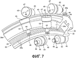
фиг.7 - вид в перспективе, подобный таковому по фиг.6, но с обоймами подшипников, снятыми для ясности.FIG. 7 is a perspective view similar to that of FIG. 6, but with bearing shells removed for clarity.
ОПИСАНИЕ ПРЕДПОЧТИТЕЛЬНЫХ ВАРИАНТОВ ОСУЩЕСТВЛЕНИЯDESCRIPTION OF PREFERRED EMBODIMENTS
Фиг.1 представляет вид предшествующего уровня техники части передней кромки крыла и предкрылка и уже был описан выше.1 is a view of the prior art of a portion of a leading edge of a wing and a slat, and has already been described above.
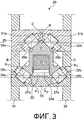
Далее, со ссылкой на фиг.2 и 3, показан упрощенный вид в разрезе через опорную сборку 20 направляющей предкрылка согласно варианту осуществления изобретения. Этот разрез взят через изогнутый опорный рычаг предкрылка или направляющую 21 предкрылка, видимые спереди, то есть, с обзором на переднюю кромку крыла, и, таким образом сам предкрылок, который прикреплен к переднему концу опорного рычага 21 предкрылка, не видимы на этом чертеже, и опорный рычаг 21 предкрылка поворачивается вокруг теоретического центра или оси (не показанных на фигурах) в направлении от листа к наблюдателю, когда предкрылок 2, прикрепленный к опорному рычагу 21 предкрылка, выпущен.Next, with reference to FIGS. 2 and 3, a simplified sectional view through a
Как на виде предшествующего уровня техники по фиг.1, изогнутый опорный рычаг 21 предкрылка имеет дуговой паз или вырез 22 по своей длине, в который вмещена направляющая 23 предкрылка, прикрепленная к опорному рычагу 21 предкрылка. Направляющая 23 предкрылка имеет зубья 23a, тянущиеся вдоль ее нижней открытой поверхности, для зацепления с ведущей шестерней (не показанной, но подобной ведущей шестерне 8, показанной на фиг.1), чтобы приводить в движение опорный рычаг 21 предкрылка между положениями выпущенного предкрылка и втянутого предкрылка, как обычно.As in the prior art of FIG. 1, the curved
Опорный рычаг 21 предкрылка тянется внутри пространства, сформированного между двумя нервюрами 24, формирующими часть конструкции крыла летательного аппарата, и обойма 25 верхнего подшипника жестко прикреплена к и тянется между нервюрами 24. Вал 26 также жестко смонтирован и тянется между нервюрами 24 под опорным рычагом 21 предкрылка. Два подшипника 27a, 27b с возможностью вращения установлены на валу 26 и находятся в контакте качения с соответствующими опорными поверхностями 28a, 28b на опорном рычаге 21 предкрылка. Будет принято во внимание, что ось вращения (A-A - смотрите фиг.2) подшипников 27a, 27b, и соответствующие опорные поверхности 28a, 28b обе параллельны оси вращения (X-X) опорного рычага 21 предкрылка, в то время как он перемещается между своим выпущенном и втянутым положениями. Эти подшипники, поэтому, способны сопротивляться нагрузкам, приложенным к опорному рычагу 21 предкрылка только в вертикальном направлении, то есть, в направлении стрелки «F» на фиг.2, но не могут нести никакую боковую нагрузку опорного рычага 21 предкрылка. Однако, верхняя сторона опорного рычага 21 предкрылка поделена на две опорные поверхности 29a, 29b, каждая из которых тянется вверх от боковой стороны опорного рычага 21 предкрылка под углом к гребню 30. В результате, верхняя грань опорного рычага 21 предкрылка имеет треугольный профиль в поперечном сечении, хотя предусмотрено, что опорным поверхностям 29a, 29b не нужно сходиться на гребне, и может быть область между двумя опорными поверхностями, которые тянутся параллельно оси опорного рычага 21 предкрылка.The
Пара верхних подшипников 31a, 31b с возможностью вращения установлена на раздельно наклонные валы 32a, 32b, принятые внутрь верхней обоймы 25 подшипника, и подшипник 31a находится в контакте качения с наклонной опорной поверхностью 29a, тогда как подшипник 31b находится в контакте качения с наклонной опорной поверхностью 29b. Валы 32a, 32b наклонены, из условия чтобы ось вращения (B-B и C-C) каждого подшипника 31a, 31b была параллельна своей соответствующей опорной поверхности 29a, 29b. Будет принято во внимание, что, в результате ориентации верхних подшипников 31a, 31b таким образом, что поверхность контакта между подшипниками 31a, 31b и их соответствующими опорными поверхностями 29a, 29b, больше не параллельны оси вращения опорного рычага 21 предкрылка, верхние подшипники 31a, 31b теперь способны противодействовать усилиям боковой нагрузки, приложенным к опорному рычагу 21 предкрылка, то есть, усилиям, приложенным в направлении стрелок «L» на фиг.2, в дополнение к вертикальным нагрузкам. Поэтому, дополнительные подшипники боковой нагрузки, традиционно используемые в опорных сборках предкрылка предшествующего уровня техники, больше не требуются, тем самым, снижая вес и экономя пространство и затраты.A pair of
Будет принято во внимание, что, так как опорные поверхности 29a, 29b не параллельны оси вращения опорного рычага предкрылка, расстояние по радиусу от оси X-X опорного рычага предкрылка изменяется в направлении вдоль оси между максимальным расстоянием D1 и минимальным расстоянием D2, как указано на фиг.2. Будет отмечено, что расстояние по радиусу уменьшается в первом направлении (справа налево, как показано на фиг.2) для левой опорной поверхности 29a, и что расстояние по радиусу уменьшается во втором направлении (слева направо, как показано на фиг.2) для правой опорной поверхности 29b.It will be appreciated that since the supporting
Фиг.3 показывает компоновку, подобную таковой на фиг.2 за исключением того, что нижние подшипники 27a, 27b скомпонованы таким же образом, как верхние подшипники 31a, 31b (и теперь имеют отдельные оси A1-A1 и A2-A2), а нижние опорные поверхности 28a, 28b опорного рычага 21 предкрылка также наклонены относительно оси вращения опорного рычага 21 предкрылка. Каждый из нижних подшипников 27a, 27b также с возможностью вращения установлен на отдельные валы 32a, 32b, вмещенные в нижнюю обойму 33,которая тянется между нервюрами 24 крыла летательного аппарата. В этом варианте осуществления, как нижние, так и верхние подшипники 27a, 27b; 31a, 31b способны противодействовать обеим, боковым и вертикальным, нагрузкам, приложенным к опорному рычагу 21 предкрылка.FIG. 3 shows an arrangement similar to that of FIG. 2 except that the
Хотя нижние и/или верхние опорные поверхности 28a, 28b; 29a, 29b показаны в качестве являющихся наклонными на 45 градусов относительно оси, вокруг которой поворачивается опорный рычаг 21 предкрылка, будет приниматься во внимание, что опорные поверхности 28a, 28b; 29a, 29b могли бы допускать любой угол меду 0 и 90 градусами в зависимости от нагрузки, которую необходимо выдерживать подшипникам. Например, усилия боковых нагрузок будут существенно меньшими, чем усилия вертикальных нагрузок, а значит, опорные поверхности будут наклонены так, что их связанные подшипники расположены, с тем чтобы противодействовать большему усилию вертикальной нагрузки, чем усилию боковой нагрузки.Although the lower and / or
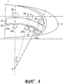
Обобщенный вид сбоку компоновки, показанной на фиг.2, проиллюстрирован на фиг.4, и на которой предкрылок 2 может быть виден в своем втянутом положении, в котором он находится против передней кромки крыла 1. В этом варианте осуществления, есть три верхних обоймы 25, скомпонованные разнесенными на некоторый угол вокруг теоретического центра или оси вращения «X» опорного рычага 21 предкрылка над опорным рычагом 21 предкрылка, каждая из которых вмещает два подшипника 31a, 31b, как показано и описано со ссылкой на фиг.2. Также показано три нижних подшипника 27a, разнесенных друг от друга на некоторый угол вокруг оси «X» вращения опорного рычага 21 предкрылка и соответствующих каждому из верхних наборов подшипников 31a, 31b. Ведущая шестерня 33 в зацеплении с зубьями 23a на направляющей 23 предкрылка также показана расположенной между двумя нижними подшипниками 27a для приведения в движение опорного рычага 21 предкрылка между его выпущенным и втянутым положениями.A generalized side view of the arrangement shown in FIG. 2 is illustrated in FIG. 4, and in which the
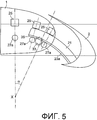
Такой же обобщенный вид сбоку показан на фиг.5 за исключением того, что, на этом виде, предкрылок 2 показан в своем максимально выпущенном положении. Для достижения этого положения, опорный рычаг 21 предкрылка повернулся вокруг своей оси «X» на угол приблизительно 24 градуса (указанный углом α на фиг.4 и 5). Может быть видно, что, в этом положении, задний набор подшипников 27a, 27b; 31a, 31b, то есть тех, которые дальше всего от передней кромки крыла или предкрылка 2, являются избыточными, так как опорный рычаг 21 предкрылка больше не зацепляется с этими подшипниками и полностью поддерживается оставшимися двумя наборами подшипников, близко расположенными к передней кромке крыла 1. Предусмотрено, что этот задний набор подшипников вполне мог бы быть исключен, хотя может быть полезно предусмотреть задний набор подшипников для обеспечения дополнительной опоры для предкрылка во время крейсерского полета, когда предкрылок 2 втянут. Чтобы направлять свободный конец опорного рычага 21 предкрылка обратно в зацепление с задним набором подшипников, когда опорный рычаг 21 предкрылка втянут, свободный конец опорного рычага 21 предкрылка может иметь небольшую фаску или скошенную поверхность 35.The same generalized side view is shown in FIG. 5 except that, in this view, the
Так как больше нет никакой потребности предусматривать дополнительные подшипники боковой нагрузки между подшипниками вертикальной нагрузки, наборы подшипников могут быть размещены гораздо ближе друг к другу, тем самым, экономя пространство внутри конструкции крыла и предоставляя возможность для являющегося закономерным следствием уменьшения длины опорного рычага 21 предкрылка, так как опорный рычаг 21 предкрылка по-прежнему может поддерживаться двумя наборами подшипников, даже при полном выпуске предкрылка 2. Как следствие уменьшения длины опорного рычага 21 предкрылка, больше нет необходимости пронизывать лонжерон 6, и направляющая также больше может не требоваться. В качестве дополнительного преимущества, также можно компоновать соответствующие верхний и нижний подшипники так, что линия, тянущаяся от теоретического центра или оси вращения опорного рычага 21 предкрылка, распространяется через ось обоих, нижнего и верхнего, подшипников, так как подшипники могут быть размещены на истинных радиальных центральных линиях, которые проходят через теоретический центр вращения опорного рычага предкрылка, тем самым, улучшая грузоподъемность. В конфигурации предшествующего уровня техники, это невозможно вследствие нехватки пространства и потребности предусматривать дополнительные подшипники боковой нагрузки между подшипниками вертикальной нагрузки.Since there is no longer any need to provide additional lateral load bearings between the vertical load bearings, the bearing sets can be placed much closer to each other, thereby saving space inside the wing structure and providing an opportunity for the
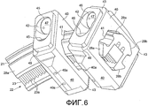
Далее будет сделана ссылка на фиг.6 и 7, которые иллюстрируют более практичную конфигурацию обобщенного варианта осуществления по фиг.3, и на которых может быть виден опорный рычаг 21 предкрылка, имеющий верхние поверхности 29a, 29b прилегания и нижние поверхности 28a, 28b прилегания. Рейка 23 предкрылка вмещена в пазу 22 и имеет зубья 23a для зацепления с ведущей шестерней (не показана).Next, reference will be made to FIGS. 6 and 7, which illustrate a more practical configuration of the generalized embodiment of FIG. 3, and on which a
Подшипники 27a, 27b; 31a, 31b, набор которых установлен внутри единой обоймы 40, которая имеет проем 41, имеющий форму для приема опорного рычага 21 предкрылка через него. Обойма 41 имеет вырезы 42 на своих торцевых поверхностях 43 для облегчения вставки и извлечения подшипников 27a, 27b; 31a, 31b, которые могут быть яснее видны на фиг.7, которая показывает тот же самый вид, что и фиг.6, но с обоймами 40, опущенными для ясности. Каждый подшипник 27a, 27b; 31a, 31b содержит несущий элемент 43 (смотрите фиг.7), который с возможностью вращения установлен на валу 44. Вал 44 имеет часть 45 торцевого колпака или головки, а конец вала 44, дальний от колпака 45, является резьбовой частью на 46 для резьбового соединения с соответствующим резьбовым отверстием (не показано) в обойме 40, когда вал 44, вместе с несущим элементом 43, установленным на нем, вставлен через отверстие 42 в торцевых поверхностях обоймы 40. Колпак 45 поддерживается в пределах выреза 42 в обойме и может быть снабжен уплотнительным элементом для уплотнения любого зазора между колпаком 45 и стенкой выреза 42, чтобы предотвращать попадание грязи. Верхняя поверхность 47 колпака 45 может быть снабжена отверстиями 48 для зацепления с инструментом для ее вставки в и ее монтажа в обойму 40. Обойма 40 также может быть снабжена дренажными отверстиями 40a для предоставления возможности выхода воды из обоймы 40.
Торцевые поверхности 43 обоймы 40 снабжены заплечиками 49. Предусмотрено, что таковые будут профилированы, чтобы давать каждой обойме 40, укомплектованной своими установленными внутри подшипниками 27a, 27b, 31a, 31b, возможность вставляться в крыло 1 летательного аппарата во время сборки, так что заплечики 49 зацепляются между соответствующими нервюрами 5, тем самым, располагая соответственные обоймы 40 в правильном положении, чтобы принимать опорный рычаг 21 предкрылка.The end surfaces 43 of the
Варианты осуществления изобретения существенно сокращают требуемое количество подшипников над традиционной опорной сборкой предкрылка на вплоть до 50%, так как боковые нагрузки теперь уравновешены теми же самыми подшипниками, которые противодействуют вертикальным нагрузкам, а значит, больше нет никакой необходимости предусматривать отдельные подшипники боковой нагрузки. Это может давать возможность значительного снижения веса и/или сильно уменьшает конструктивные ограничения пространства в плотно заполненной передней кромке крыла.Embodiments of the invention significantly reduce the required number of bearings over a traditional slat support assembly by up to 50%, since side loads are now balanced by the same bearings that counteract vertical loads, which means that there is no longer any need to provide separate side load bearings. This can make it possible to significantly reduce weight and / or greatly reduce structural limitations of the space in the densely filled leading edge of the wing.
Будет принято во внимание, что вышеизложенное описание приведено только в качестве примера, и что модификации могут быть произведены в отношении опорной сборки предкрылка по настоящему изобретению, не выходя из объема прилагаемой формулы изобретения. Например, должно быть отмечено, что, в описанном выше варианте осуществления изобретения, опорный рычаг предкрылка изогнут вокруг оси и поворачивается вокруг упомянутой оси между убранным и выпущенном положениями. Однако предусмотрено, что опорный рычаг предкрылка мог бы следовать некруговое траектории, такой как эллиптическая или линейная траектория и/или что опорный рычаг предкрылка может не быть изогнутым.It will be appreciated that the foregoing description is by way of example only and that modifications may be made to the support assembly of the slat of the present invention without departing from the scope of the appended claims. For example, it should be noted that, in the above-described embodiment of the invention, the slat support arm is bent around an axis and rotates around said axis between the retracted and released positions. However, it is contemplated that the slat support arm could follow a non-circular path, such as an elliptical or linear path, and / or that the slat support arm may not be bent.
Claims (15)
Applications Claiming Priority (3)
| Application Number | Priority Date | Filing Date | Title |
|---|---|---|---|
| GBGB0816022.8A GB0816022D0 (en) | 2008-09-03 | 2008-09-03 | Slat support assembly |
| GB0816022.8 | 2008-09-03 | ||
| PCT/GB2009/051078 WO2010026410A2 (en) | 2008-09-03 | 2009-08-27 | Slat support assembly |
Publications (2)
| Publication Number | Publication Date |
|---|---|
| RU2011112784A RU2011112784A (en) | 2012-10-10 |
| RU2502636C2 true RU2502636C2 (en) | 2013-12-27 |
Family
ID=39866171
Family Applications (1)
| Application Number | Title | Priority Date | Filing Date |
|---|---|---|---|
| RU2011112784/11A RU2502636C2 (en) | 2008-09-03 | 2009-08-27 | Slat support assy |
Country Status (9)
| Country | Link |
|---|---|
| US (1) | US9016636B2 (en) |
| EP (1) | EP2318269B1 (en) |
| JP (1) | JP5497764B2 (en) |
| CN (1) | CN102143886B (en) |
| BR (1) | BRPI0918493A2 (en) |
| CA (1) | CA2734686C (en) |
| GB (1) | GB0816022D0 (en) |
| RU (1) | RU2502636C2 (en) |
| WO (1) | WO2010026410A2 (en) |
Families Citing this family (29)
| Publication number | Priority date | Publication date | Assignee | Title |
|---|---|---|---|---|
| GB0722425D0 (en) * | 2007-11-15 | 2007-12-27 | Airbus Uk Ltd | Slat support funk plate |
| US10400818B2 (en) | 2007-12-06 | 2019-09-03 | Roller Bearing Company Of America, Inc. | Track roller bearings with rolling elements or liners |
| CN101988570B (en) * | 2009-07-31 | 2014-08-20 | 中国商用飞机有限责任公司 | Design method of gears and racks for airplane slat actuators |
| GB201006099D0 (en) * | 2010-04-13 | 2010-05-26 | Airbus Operations Ltd | Slat support assembly |
| GB201209686D0 (en) * | 2012-05-31 | 2012-07-18 | Airbus Operations Ltd | A slat support assembly |
| JP6144487B2 (en) * | 2012-12-26 | 2017-06-07 | 三菱航空機株式会社 | Flap deployment device and aircraft |
| CN103612749B (en) * | 2013-11-27 | 2016-06-22 | 中国航空工业集团公司西安飞机设计研究所 | A kind of adjustable leading edge slat of attitude |
| GB2527490A (en) * | 2014-04-17 | 2015-12-30 | Ip Dept Airbus Operations Ltd | A bearing block for a slat support assembly |
| EP3303122A2 (en) * | 2015-06-03 | 2018-04-11 | Aerosud Technology Solutions (pty) Ltd. | Composite slat can assembly |
| GB201522327D0 (en) * | 2015-12-17 | 2016-02-03 | Airbus Operations Ltd | Wing structure |
| EP3326909B1 (en) * | 2016-11-23 | 2019-10-02 | Airbus Operations GmbH | Slat assembly |
| EP3378762A1 (en) | 2017-03-24 | 2018-09-26 | Airbus Operations GmbH | Wing for an aircraft |
| EP3378760A1 (en) * | 2017-03-24 | 2018-09-26 | Airbus Operations GmbH | Wing for an aircraft |
| ES2878314T3 (en) | 2017-04-26 | 2021-11-18 | Asco Ind Nv | Guide assembly for a track carrying the aerodynamic leading edge lift device |
| US11577819B2 (en) | 2017-04-28 | 2023-02-14 | Airbus Operations Gmbh | Wing for an aircraft |
| CN110546065B (en) * | 2017-04-28 | 2023-09-05 | 空中客车运作有限责任公司 | Aircraft wing and connection assembly therein and aircraft with such a wing |
| ES2899168T3 (en) * | 2017-04-28 | 2022-03-10 | Airbus Operations Gmbh | aircraft wing |
| EP3444182B1 (en) * | 2017-08-18 | 2023-01-18 | Airbus Operations GmbH | Wing for an aircraft |
| US10364019B2 (en) * | 2017-12-13 | 2019-07-30 | Thomas Hsueh | Aircraft flap mechanism |
| ES2886667T3 (en) | 2017-12-19 | 2021-12-20 | Asco Ind Nv | Deployment system for an airfoil high lift leading edge device |
| WO2019154698A1 (en) * | 2018-02-06 | 2019-08-15 | Airbus Operations Gmbh | Wing for an aircraft |
| US11608156B2 (en) * | 2019-03-26 | 2023-03-21 | Yaborä Indústria Aeronáutica S.A. | Lateral roller assemblies for wing leading edge slat tracks |
| EP3718881B1 (en) | 2019-03-29 | 2022-10-12 | Airbus Operations GmbH | Wing for an aircraft |
| US11420727B2 (en) | 2019-07-25 | 2022-08-23 | Airbus Operations Gmbh | Airfoil arrangement for an aircraft |
| EP4032801B1 (en) | 2021-01-22 | 2024-08-28 | Airbus Operations GmbH | Wing for an aircraft |
| EP4032803A1 (en) | 2021-01-25 | 2022-07-27 | Airbus Operations GmbH | A linear drive device for an aircraft, a drive arrangement and an aircraft having such a linear drive device |
| US11897613B2 (en) | 2021-06-08 | 2024-02-13 | Airbus Operations Gmbh | Wing for an aircraft |
| EP4137401A1 (en) * | 2021-08-18 | 2023-02-22 | Airbus Operations GmbH | High-lift device connection assembly as well as wing and aircraft equipped therewith |
| BE1030173B1 (en) * | 2022-01-11 | 2023-08-10 | Sonaca | MOBILE LEADING EDGE FLAP WITH MULTIPLE STRUCTURE PASSAGE PATHS |
Citations (4)
| Publication number | Priority date | Publication date | Assignee | Title |
|---|---|---|---|---|
| GB593303A (en) * | 1944-03-06 | 1947-10-14 | Sncan | Guiding-device for slide-rod |
| EP0291328A2 (en) * | 1987-05-13 | 1988-11-17 | British Aerospace Public Limited Company | A mechanism for supporting and extending a high lift device for aircraft wings |
| RU2114029C1 (en) * | 1997-07-03 | 1998-06-27 | Титов Андрей Анатольевич | Kinesthetic device for control of aircraft engines |
| RU30705U1 (en) * | 2003-02-03 | 2003-07-10 | Федеральное государственное унитарное предприятие Лётно-исследовательский институт им. М.М.Громова | Executive mechanism for automatic aircraft control |
Family Cites Families (13)
| Publication number | Priority date | Publication date | Assignee | Title |
|---|---|---|---|---|
| GB1572004A (en) | 1978-03-30 | 1980-07-23 | Hawker Siddeley Aviation Ltd | Aircraft wings |
| US4286649A (en) | 1980-06-16 | 1981-09-01 | Rokop Corporation | Apparatus for storing a continuous casting starting bar in elevated position |
| EP0227643A3 (en) | 1980-08-13 | 1988-07-20 | The Boeing Company | Extendible airfoil track assembly |
| US4614382A (en) * | 1984-09-21 | 1986-09-30 | Hiroshi Teramachi | Straight sliding roller bearing |
| JPS6196213A (en) * | 1984-10-16 | 1986-05-14 | Hiroshi Teramachi | Linear sliding roller bearing |
| US4753402A (en) | 1985-12-30 | 1988-06-28 | The Boeing Company | Biased leading edge slat apparatus |
| GB2304656B (en) * | 1995-08-26 | 1999-10-13 | British Aerospace | Deployment mechanisms for aircraft auxiliary aerofoils |
| JPH10252763A (en) * | 1997-03-14 | 1998-09-22 | Toyo Electric Mfg Co Ltd | Bearing holding device |
| FR2840657B1 (en) * | 2002-06-05 | 2004-11-26 | Roulements Soc Nouvelle | BEARING WITH INTEGRATED GEAR |
| GB2390248A (en) * | 2002-06-28 | 2003-12-31 | Sony Uk Ltd | Watermarking a reduced bandwidth version of material |
| US7101297B2 (en) * | 2004-06-10 | 2006-09-05 | Moog Inc. | Compact actuator |
| GB0722425D0 (en) * | 2007-11-15 | 2007-12-27 | Airbus Uk Ltd | Slat support funk plate |
| ES2427390T3 (en) * | 2009-10-29 | 2013-10-30 | Asco Industries | Guide rail for hyper-sustaining device |
-
2008
- 2008-09-03 GB GBGB0816022.8A patent/GB0816022D0/en not_active Ceased
-
2009
- 2009-08-27 JP JP2011525618A patent/JP5497764B2/en not_active Expired - Fee Related
- 2009-08-27 CN CN200980134428.2A patent/CN102143886B/en not_active Expired - Fee Related
- 2009-08-27 US US12/737,701 patent/US9016636B2/en not_active Expired - Fee Related
- 2009-08-27 EP EP09785540.7A patent/EP2318269B1/en not_active Not-in-force
- 2009-08-27 RU RU2011112784/11A patent/RU2502636C2/en not_active IP Right Cessation
- 2009-08-27 WO PCT/GB2009/051078 patent/WO2010026410A2/en active Application Filing
- 2009-08-27 BR BRPI0918493A patent/BRPI0918493A2/en not_active IP Right Cessation
- 2009-08-27 CA CA2734686A patent/CA2734686C/en not_active Expired - Fee Related
Patent Citations (4)
| Publication number | Priority date | Publication date | Assignee | Title |
|---|---|---|---|---|
| GB593303A (en) * | 1944-03-06 | 1947-10-14 | Sncan | Guiding-device for slide-rod |
| EP0291328A2 (en) * | 1987-05-13 | 1988-11-17 | British Aerospace Public Limited Company | A mechanism for supporting and extending a high lift device for aircraft wings |
| RU2114029C1 (en) * | 1997-07-03 | 1998-06-27 | Титов Андрей Анатольевич | Kinesthetic device for control of aircraft engines |
| RU30705U1 (en) * | 2003-02-03 | 2003-07-10 | Федеральное государственное унитарное предприятие Лётно-исследовательский институт им. М.М.Громова | Executive mechanism for automatic aircraft control |
Also Published As
| Publication number | Publication date |
|---|---|
| EP2318269B1 (en) | 2015-01-28 |
| CN102143886A (en) | 2011-08-03 |
| US20110168849A1 (en) | 2011-07-14 |
| JP5497764B2 (en) | 2014-05-21 |
| RU2011112784A (en) | 2012-10-10 |
| US9016636B2 (en) | 2015-04-28 |
| BRPI0918493A2 (en) | 2015-12-01 |
| CA2734686A1 (en) | 2010-03-11 |
| EP2318269A2 (en) | 2011-05-11 |
| JP2012501895A (en) | 2012-01-26 |
| GB0816022D0 (en) | 2008-10-08 |
| CA2734686C (en) | 2014-04-15 |
| CN102143886B (en) | 2014-01-01 |
| WO2010026410A2 (en) | 2010-03-11 |
| WO2010026410A3 (en) | 2010-06-03 |
Similar Documents
| Publication | Publication Date | Title |
|---|---|---|
| RU2502636C2 (en) | Slat support assy | |
| US9296473B2 (en) | Slat support assembly | |
| US8424801B2 (en) | Slat support assembly | |
| RU2492110C2 (en) | Slat extension mechanism | |
| US11420723B2 (en) | Aircraft wing and wing tip device | |
| EP2960437B1 (en) | Variable guide vane device for a gas turbine and gas turbine equipped with such a device | |
| US9616989B2 (en) | Bearing block for a slat support assembly | |
| US11780554B2 (en) | Deployment system for an airfoil high lift leading edge device | |
| US10464659B2 (en) | Vertical stabilizer for an aircraft | |
| EP3395678B1 (en) | Guidance assembly for an airfoil leading edge high-lift device carrier track | |
| DE102015211678B4 (en) | Gear device | |
| CA2803396C (en) | Low profile jettisonable door system | |
| US11608156B2 (en) | Lateral roller assemblies for wing leading edge slat tracks | |
| DE102015110687B4 (en) | VALVE TIMING DEVICE | |
| EP2686566B1 (en) | Rolling bearing with a lateral filling opening | |
| EP3850997A1 (en) | Blade assembly and food processor having same | |
| US10899438B2 (en) | Seals for rotor system fairings | |
| DE10039923A1 (en) | Valve controller for internal combustion engines has sealing element on outer end of rotor blade to form seal between outer end of blade and inner peripheral surface of housing | |
| DE112013006206T5 (en) | Camshaft adjuster with center bolt | |
| CN106884952A (en) | Gear mechanism | |
| ES2970709T3 (en) | Adjustable roller unit for moving a slat of an airplane wing | |
| EP4032804B1 (en) | Wing for an aircraft | |
| WO2024052867A1 (en) | Variable pitch propeller for watercraft | |
| JP6122294B2 (en) | Marine propeller and its boss | |
| DE102007046930A1 (en) | Gas turbine has outer housing, separating blades, shaft, disk with assembled working elements, inlet and outlet openings and current divider, where float assembly with baffle is arranged on turbine shaft |
Legal Events
| Date | Code | Title | Description |
|---|---|---|---|
| MM4A | The patent is invalid due to non-payment of fees |
Effective date: 20160828 |