US11217783B2 - Negative electrode active material for lithium secondary battery, negative electrode including the same, and lithium secondary battery including the negative electrode - Google Patents
Negative electrode active material for lithium secondary battery, negative electrode including the same, and lithium secondary battery including the negative electrode Download PDFInfo
- Publication number
- US11217783B2 US11217783B2 US16/225,435 US201816225435A US11217783B2 US 11217783 B2 US11217783 B2 US 11217783B2 US 201816225435 A US201816225435 A US 201816225435A US 11217783 B2 US11217783 B2 US 11217783B2
- Authority
- US
- United States
- Prior art keywords
- carbon
- negative electrode
- electrode active
- active material
- based material
- Prior art date
- Legal status (The legal status is an assumption and is not a legal conclusion. Google has not performed a legal analysis and makes no representation as to the accuracy of the status listed.)
- Active, expires
Links
Images


Classifications
-
- C—CHEMISTRY; METALLURGY
- C01—INORGANIC CHEMISTRY
- C01B—NON-METALLIC ELEMENTS; COMPOUNDS THEREOF; METALLOIDS OR COMPOUNDS THEREOF NOT COVERED BY SUBCLASS C01C
- C01B32/00—Carbon; Compounds thereof
- C01B32/20—Graphite
- C01B32/205—Preparation
-
- C—CHEMISTRY; METALLURGY
- C01—INORGANIC CHEMISTRY
- C01B—NON-METALLIC ELEMENTS; COMPOUNDS THEREOF; METALLOIDS OR COMPOUNDS THEREOF NOT COVERED BY SUBCLASS C01C
- C01B32/00—Carbon; Compounds thereof
- C01B32/05—Preparation or purification of carbon not covered by groups C01B32/15, C01B32/20, C01B32/25, C01B32/30
-
- C—CHEMISTRY; METALLURGY
- C01—INORGANIC CHEMISTRY
- C01B—NON-METALLIC ELEMENTS; COMPOUNDS THEREOF; METALLOIDS OR COMPOUNDS THEREOF NOT COVERED BY SUBCLASS C01C
- C01B32/00—Carbon; Compounds thereof
- C01B32/20—Graphite
- C01B32/21—After-treatment
-
- H—ELECTRICITY
- H01—ELECTRIC ELEMENTS
- H01M—PROCESSES OR MEANS, e.g. BATTERIES, FOR THE DIRECT CONVERSION OF CHEMICAL ENERGY INTO ELECTRICAL ENERGY
- H01M10/00—Secondary cells; Manufacture thereof
- H01M10/05—Accumulators with non-aqueous electrolyte
- H01M10/052—Li-accumulators
- H01M10/0525—Rocking-chair batteries, i.e. batteries with lithium insertion or intercalation in both electrodes; Lithium-ion batteries
-
- H—ELECTRICITY
- H01—ELECTRIC ELEMENTS
- H01M—PROCESSES OR MEANS, e.g. BATTERIES, FOR THE DIRECT CONVERSION OF CHEMICAL ENERGY INTO ELECTRICAL ENERGY
- H01M4/00—Electrodes
- H01M4/02—Electrodes composed of, or comprising, active material
- H01M4/04—Processes of manufacture in general
- H01M4/0471—Processes of manufacture in general involving thermal treatment, e.g. firing, sintering, backing particulate active material, thermal decomposition, pyrolysis
-
- H—ELECTRICITY
- H01—ELECTRIC ELEMENTS
- H01M—PROCESSES OR MEANS, e.g. BATTERIES, FOR THE DIRECT CONVERSION OF CHEMICAL ENERGY INTO ELECTRICAL ENERGY
- H01M4/00—Electrodes
- H01M4/02—Electrodes composed of, or comprising, active material
- H01M4/13—Electrodes for accumulators with non-aqueous electrolyte, e.g. for lithium-accumulators; Processes of manufacture thereof
- H01M4/133—Electrodes based on carbonaceous material, e.g. graphite-intercalation compounds or CFx
-
- H—ELECTRICITY
- H01—ELECTRIC ELEMENTS
- H01M—PROCESSES OR MEANS, e.g. BATTERIES, FOR THE DIRECT CONVERSION OF CHEMICAL ENERGY INTO ELECTRICAL ENERGY
- H01M4/00—Electrodes
- H01M4/02—Electrodes composed of, or comprising, active material
- H01M4/13—Electrodes for accumulators with non-aqueous electrolyte, e.g. for lithium-accumulators; Processes of manufacture thereof
- H01M4/139—Processes of manufacture
- H01M4/1393—Processes of manufacture of electrodes based on carbonaceous material, e.g. graphite-intercalation compounds or CFx
-
- H—ELECTRICITY
- H01—ELECTRIC ELEMENTS
- H01M—PROCESSES OR MEANS, e.g. BATTERIES, FOR THE DIRECT CONVERSION OF CHEMICAL ENERGY INTO ELECTRICAL ENERGY
- H01M4/00—Electrodes
- H01M4/02—Electrodes composed of, or comprising, active material
- H01M4/36—Selection of substances as active materials, active masses, active liquids
- H01M4/362—Composites
- H01M4/366—Composites as layered products
-
- H—ELECTRICITY
- H01—ELECTRIC ELEMENTS
- H01M—PROCESSES OR MEANS, e.g. BATTERIES, FOR THE DIRECT CONVERSION OF CHEMICAL ENERGY INTO ELECTRICAL ENERGY
- H01M4/00—Electrodes
- H01M4/02—Electrodes composed of, or comprising, active material
- H01M4/36—Selection of substances as active materials, active masses, active liquids
- H01M4/58—Selection of substances as active materials, active masses, active liquids of inorganic compounds other than oxides or hydroxides, e.g. sulfides, selenides, tellurides, halogenides or LiCoFy; of polyanionic structures, e.g. phosphates, silicates or borates
- H01M4/583—Carbonaceous material, e.g. graphite-intercalation compounds or CFx
- H01M4/587—Carbonaceous material, e.g. graphite-intercalation compounds or CFx for inserting or intercalating light metals
-
- H—ELECTRICITY
- H01—ELECTRIC ELEMENTS
- H01M—PROCESSES OR MEANS, e.g. BATTERIES, FOR THE DIRECT CONVERSION OF CHEMICAL ENERGY INTO ELECTRICAL ENERGY
- H01M4/00—Electrodes
- H01M4/02—Electrodes composed of, or comprising, active material
- H01M4/62—Selection of inactive substances as ingredients for active masses, e.g. binders, fillers
- H01M4/624—Electric conductive fillers
- H01M4/625—Carbon or graphite
-
- C—CHEMISTRY; METALLURGY
- C01—INORGANIC CHEMISTRY
- C01P—INDEXING SCHEME RELATING TO STRUCTURAL AND PHYSICAL ASPECTS OF SOLID INORGANIC COMPOUNDS
- C01P2004/00—Particle morphology
- C01P2004/80—Particles consisting of a mixture of two or more inorganic phases
-
- H—ELECTRICITY
- H01—ELECTRIC ELEMENTS
- H01M—PROCESSES OR MEANS, e.g. BATTERIES, FOR THE DIRECT CONVERSION OF CHEMICAL ENERGY INTO ELECTRICAL ENERGY
- H01M4/00—Electrodes
- H01M4/02—Electrodes composed of, or comprising, active material
- H01M2004/021—Physical characteristics, e.g. porosity, surface area
-
- H—ELECTRICITY
- H01—ELECTRIC ELEMENTS
- H01M—PROCESSES OR MEANS, e.g. BATTERIES, FOR THE DIRECT CONVERSION OF CHEMICAL ENERGY INTO ELECTRICAL ENERGY
- H01M4/00—Electrodes
- H01M4/02—Electrodes composed of, or comprising, active material
- H01M2004/026—Electrodes composed of, or comprising, active material characterised by the polarity
- H01M2004/027—Negative electrodes
-
- Y—GENERAL TAGGING OF NEW TECHNOLOGICAL DEVELOPMENTS; GENERAL TAGGING OF CROSS-SECTIONAL TECHNOLOGIES SPANNING OVER SEVERAL SECTIONS OF THE IPC; TECHNICAL SUBJECTS COVERED BY FORMER USPC CROSS-REFERENCE ART COLLECTIONS [XRACs] AND DIGESTS
- Y02—TECHNOLOGIES OR APPLICATIONS FOR MITIGATION OR ADAPTATION AGAINST CLIMATE CHANGE
- Y02E—REDUCTION OF GREENHOUSE GAS [GHG] EMISSIONS, RELATED TO ENERGY GENERATION, TRANSMISSION OR DISTRIBUTION
- Y02E60/00—Enabling technologies; Technologies with a potential or indirect contribution to GHG emissions mitigation
- Y02E60/10—Energy storage using batteries
Definitions
- Embodiments of the present disclosure relate to a negative electrode active material for a lithium secondary battery, a negative electrode including the same, and a lithium secondary battery including the negative electrode.
- Lithium batteries are used as power sources for portable electronic devices such as video cameras, mobile phones, laptops, or the like.
- a rechargeable lithium secondary battery may be capable of high-speed charging and may have an energy density per unit weight that is more than three times the energy density per unit weight of existing lead storage batteries, nickel-cadmium batteries, nickel metal hydrogen batteries, and nickel-zinc batteries.
- a lithium secondary battery produces electrical energy by oxidation and reduction reactions of lithium ions which are intercalated/deintercalated in a positive electrode and a negative electrode in a state where an organic electrolytic solution or a polymer electrolytic solution is filled between a positive electrode and a negative electrode that each include an active material capable of intercalating and deintercalating lithium ions.
- a representative example of a negative electrode active material for a lithium secondary battery is a carbon-based material such as graphite.
- a carbon-based material such as graphite.
- Such a carbon-based material is excellent in terms of battery safety since it allows lithium ions to be intercalated in a battery and to exist in a stable state.
- a carbon-based material may include any suitable natural graphite and artificial graphite available in the art.
- natural graphite has a high energy density and a high energy capacity, capacity retention characteristics of natural graphite deteriorate over time due to cracking that occurs as a result of expansion during charging, and thus, artificial graphite is mainly used instead of natural graphite.
- One or more embodiments of the present disclosure include a composite negative electrode active material having suppressed or reduced volume expansion and improved output and rate characteristics.
- One or more embodiments include a negative electrode including the composite negative electrode active material.
- One or more embodiments include a lithium secondary battery including the negative electrode.
- One or more embodiments include a method of preparing the composite negative electrode active material.
- a composite negative electrode active material includes:
- first carbon-based material and the second carbon-based material have respective particle diameters that are different from each other, and
- the second carbon-based material has a particle strength in a range of 100 MPa to 150 MPa and a Young's modulus in a range of 1.5 GPa to 4 GPa.
- a method of preparing the composite negative electrode active material includes:
- a negative electrode includes the composite negative electrode active material.
- a lithium secondary battery includes the negative electrode.
- FIG. 1 is a scanning electron microscope (SEM) image showing a first carbon-based material of the artificial graphite secondary particles
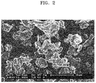
- FIG. 2 is an SEM image showing a second carbon-based material of the high-strength and high-output artificial graphite primary particles
- FIG. 3 is an SEM image showing a composite negative electrode active material in which a first carbon-based material and a second carbon-based material are combined with each other;
- FIG. 4 is a graph showing expansion rates of pouch-type cells (e.g., pouch-shaped cells) prepared according to Example 2 and Comparative Examples 7 to 12 after 25 charging and discharging cycles of the pouch-type cells;
- pouch-type cells e.g., pouch-shaped cells
- FIG. 5 is a graph showing capacity characteristics of pouch-type cells prepared according to Example 2 and Comparative Examples 7 to 12;
- FIG. 6 is a schematic view of a structure of a lithium secondary battery according to an embodiment.
- composite does not refer to a state where a plurality of components having different properties are merely mixed and physically contacted, but instead refers to a state where components have a set or certain bonding relationship through mechanochemical, electrochemical, and/or chemical reactions that cannot be reached by a simple mixing process.
- composite negative electrode active material refers to a negative electrode active material that is obtained through mechanochemical, electrochemical, and/or chemical reactions.
- first may be used to describe a plurality of components having different properties, but the plurality of components should not be limited by these terms. These terms are used to distinguish one element, component, region, layer or section from another element, component, region, layer or section. Thus, a first element, component, region, layer or section described below could be termed a second element, component, region, layer or section, without departing from the spirit and scope of the present disclosure.
- a composite negative electrode active material including: a first carbon-based material; and a second carbon-based material positioned on a surface of the first carbon-based material, wherein the first carbon-based material and the second carbon-based material are different from each other
- the second carbon-based material has a particle strength in a range of 100 MPa to 150 MPa and a Young's modulus in a range of 1.5 GPa to 4 GPa.
- the particle strength and the Young's modulus are each used as an measurement of the physical strength of particles.
- the second carbon-based material having a particle strength in a range of 100 MPa to 150 MPa and a Young's modulus in a range of 1.5 GPa to 4 GPa is positioned on a surface of the first carbon-based material, the expansion of the first carbon-based material during charging may be effectively controlled or reduced. Consequently, the cracking of the composite negative electrode active material during charging and discharging may be prevented or reduced, thereby improving cycle characteristics and lifespan characteristics.
- the first carbon-based material may have a particle strength in a range of 15 MPa to 40 MPa and a Young's modulus in a range of 0.1 GPa to 0.4 GPa.
- the first carbon-based material may include artificial graphite having a medium particle diameter (D 50 ) in a range of 15 ⁇ m to 30 ⁇ m.
- D 50 is defined as a particle diameter with respect to 50% accumulation in the particle diameter distribution of the particles (e.g., 50% of the mass of the first carbon-based material has a particle diameter smaller than that of the D 50 particle diameter).
- the density of a negative electrode formed by using a negative electrode active material including the first carbon-based material may be increased, thereby improving discharge capacity and cycle characteristics of a lithium secondary battery including the negative electrode.
- a lithium secondary battery (a half-cell type or kind) prepared by using the first carbon-based material as the negative electrode active material may have a capacity, e.g., a discharge capacity herein, in a range of 355 mAh/g to 365 mAh/g.
- the first carbon-based material may include an artificial graphite secondary particle formed by agglomeration of a plurality of artificial graphite primary particles.
- the artificial graphite secondary particles are agglomerates of the primary particles, and accordingly, may also include voids existing among the primary particles. Due to such voids existing among the primary particles, the secondary particles may increase a surface area in contact with lithium ions, and as a result, the capacity characteristics may be improved.
- the first carbon-based material may have high capacity and high density characteristics, and such high capacity and high density characteristics may be identified by X-ray diffraction analysis and measurement of pellet density.
- the first carbon-based material may have a (002) plane interval (d 002 ) in a range of 0.3355 nm to 0.3360 nm (e.g., a distance between 002 planes of the first carbon-based material may be in a range of 0.3355 nm to 0.3360 nm) as measured by X-ray diffraction analysis, and have pellet density in a range of 1.65 g/cc to 2.0 g/cc.
- the first carbon-based material is found to have a high degree of crystallinity, and according to a value of the pellet density, the first carbon-based material is found to have high density characteristic and excellent rolling properties.
- a negative electrode prepared by using the composite negative electrode active material including the first carbon-based material may accordingly have high density of the composite negative electrode active material as well as high capacity/high density characteristics.
- the first carbon-based material may have a Lc/La ratio in a range of 0.95 to 1.05, where Lc is a crystallite size in a c-axis direction and La is a crystallite size in an a-axis direction, as determined by X-ray diffraction analysis.
- the first carbon-based material may also have an I 002 /I 110 ratio in a range of 100 to 250, wherein I 002 is a peak intensity of the (002) plane and I 110 is a peak intensity of the (110) plane, as determined by X-ray diffraction analysis.
- the second carbon-based material may include artificial graphite primary particles having a median particle diameter D 50 in a range of 3 ⁇ m to 7 ⁇ m.
- the volume expansion of the composite negative electrode active material including the second carbon-based material during charging and discharging may be effectively suppressed or reduced.
- a negative electrode prepared by using the composite negative electrode active material including the second carbon-based material may increase the density of the composite negative electrode active material, and accordingly, a lithium secondary battery including the negative electrode may have an increased discharge capacity and improved cycle characteristics.
- a lithium secondary battery (a half-cell type or kind) prepared by using the second carbon-based material as the negative electrode active material may have a capacity, e.g., a discharge capacity herein, in a range of 330 mAh/g to 340 mAh/g.
- the second carbon-based material may have high strength and high output characteristics, and such high strength and high output characteristics may be identified by X-ray diffraction analysis and measurement of pellet density.
- the second carbon-based material may have a (002) plane interval (d 002 ) in a range of 0.336 nm to 0.337 nm (e.g. 0.3360 nm to 0.3365 nm) (e.g., a distance between 002 planes of the first carbon-based material may be in a range of 0.336 nm to 0.337 nm) as measured by X-ray diffraction analysis, and have pellet density in a range of 1.35 g/cc to 1.5 g/cc.
- the second carbon-based material may have a Lc/La ratio in a range of 0.6 to 0.9, where Lc is a crystallite size in a c-axis direction and La is a crystallite size in an a-axis direction, as determined by X-ray diffraction analysis.
- the second carbon-based material may also have an I 002 /I 110 ratio in a range of 30 to 80, wherein I 002 is a peak intensity of the (002) plane and I 110 is a peak intensity of the (110) plane, as determined by X-ray diffraction analysis.
- the first carbon-based material and the second carbon-based material may each independently be a material derived from at least one selected from hard carbon, soft carbon, and/or graphite.
- one of ordinary skill in the art may suitably or appropriately select and use the first carbon-based material or the second carbon-based material in consideration of suitability or satisfaction of the above-described properties.
- the graphite may include natural graphite, flake graphite, high crystalline graphite, microcrystalline or cryptocrystalline graphite, amorphous graphite, and/or artificial graphite.
- the soft carbon include petroleum coke, coal coke, pitch coke, needle coke, coking coal coke, and polyvinyl carbon or polyvinyl chloride carbon.
- the hard carbon include carbon black, tetrose, cellulose, phenol resin, and furan resin.
- the second carbon-based material may cover at least a portion of the surface of the first carbon-based material.
- the second carbon-based material may be on the surface of the first carbon-based material in an island shape.
- the second carbon-based material may be distributed in an island shape on (or across) the surface of the first carbon-based material.
- the first carbon-based material may be subjected to volume expansion during a battery cycle, thereby degrading lifespan and safety of the battery.
- the second carbon-based material is positioned on the surface of the first carbon-based material, the volume expansion of the battery may be effectively suppressed or reduced, and accordingly, the safety (e.g., penetration and pricking characteristics, etc.) of the battery may be also improved.
- the second carbon-based material is distributed in an island shape on the surface of the first carbon-based material, intercalation/deintercalation of lithium ions is not hindered (or is not substantially reduced).
- the output characteristics of the second carbon-based material are not degraded (or are not substantially degraded), but are rather excellent as being improved by high output characteristics of the second carbon-based material.
- a weight ratio of the first carbon-based material to the second carbon-based material may be in a range of 95:5 to 80:20.
- the weight ratio of the first carbon-based material to the second carbon-based material may be in a range of 90:10 to 80:20.
- the weight ratio of the first carbon-based material to the second carbon-based material may be in a range of 95:5 to 85:15.
- the first carbon-based material may have a higher graphitization degree than that of the second carbon-based material.
- the second carbon-based material may have a low capacity due to a lower graphitization degree than that of the first carbon-based, but is effective in terms of high output.
- graphitization degree refers to a proportion of a layered structure included in a carbon-containing material.
- having a high graphitization degree means that a carbon-containing material has a great portion of a layered structure.
- a carbon coating layer may be further included on the surface of the first carbon-based material, the surface of the second carbon-based material, or each surface of both the first carbon-based material and the second carbon-based material.
- the carbon coating layer may be positioned on a surface on which the second carbon-based material is not positioned among the surface of the second carbon-based material and the surface of the first carbon-based material.
- the carbon coating layer may be positioned only on the surface of the first carbon-based material.
- the carbon coating layer may include amorphous carbon.
- carbon included in the carbon coating layer may be a sintered product of a carbon precursor.
- the carbon precursor may be any suitable material available in the art capable of producing a carbon-based material by a sintering process.
- the carbon precursor may be at least one selected from a polymer, coal tar pitch, petroleum pitch, meso-phase pitch, coke, low-molecular heavy distillate, coal-based pitch, derivatives thereof, and combinations thereof.
- a solid electrolyte interphase (SEI) layer may be formed. Accordingly, due to selective passage of Li+ions, metal particles may be prevented from contacting an electrolyte or the like (or a likelihood or amount of such contact may be reduced). Furthermore, the carbon coating layer may suppress or reduce the volume expansion during charging and discharging, and may also act as an electron transfer path in the composite negative electrode active material, thereby contributing to improvement of electrical conductivity.
- SEI solid electrolyte interphase
- An amount of the carbon coating layer may be 8 weight % or less based on the total weight of the negative electrode active material for the lithium secondary battery, but embodiments of the present disclosure are not limited thereto.
- the amount of the carbon coating layer may be in any suitable range as long as it does not hinder (or does not unacceptably reduce) the battery characteristics of the composite negative electrode active material.
- a thickness of the carbon coating layer may be in a range of several nanometers to tens of nanometers.
- the carbon coating layer may act as a resistance layer during intercalation and deintercalation of lithium ions during charging and discharging, resulting in a decrease in capacity and a decrease in efficiency
- the composite negative electrode active material may have a core-shell structure.
- the first carbon-based material may serve as a core portion, and the second carbon-based material may serve as a shell portion.
- the core portion may include artificial graphite secondary particles having high capacity/high density
- the shell portion may include artificial graphite primary particles having high strength/high output.
- the artificial graphite primary particles having high strength/high output in the shell portion may effectively suppress or reduce the expansion of the artificial graphite secondary particle in the core portion.
- the composite negative electrode active material having such a core-shell structure may retain high capacity/high density characteristics, and may also sufficiently suppress or reduce the volume expansion during charging and discharging, thereby improving lifespan characteristics.
- the composite negative electrode active material having such a core-shell structure may include the carbon coating layer.
- the carbon layer may be positioned between the core portion and the shell portion, or on the outermost portion of the composite negative electrode active material having such a core-shell structure.
- the first carbon-based material, the second carbon-based material, and the carbon coating layer are each independently the same as described above.
- an additional amorphous carbon material may be provided to the first carbon-based secondary particles to form a carbon coating layer on the first carbon-based secondary particles.
- an additional amorphous carbon material may be provided to the composite negative electrode active material obtained in active act (b) to form a carbon coating layer on the outermost portion of the negative electrode active material.
- the forming of the carbon coating layer may include performing heat treatment at a temperature in a range of 950° C. to 1,200° C.
- the heat treatment is performed at a temperature lower than 950° C.
- the carbon coating layer to be formed may not be uniform, and when the heat treatment is performed at a temperature above 1,200° C., carbon-based materials constituting the core-shell structure may be structurally deformed. Accordingly, the characteristics of a battery including the composite negative electrode active material may be degraded.
- the active act (a) may be performed in a reactor rotating at a speed in a range of 2000 rpm to 4000 rpm.
- adding an additional amorphous carbon material may be further included.
- an amount of the additional amorphous carbon material may be suitably or appropriately selected from in consideration of the aggregation effect among the primary particles.
- graphitizing the first carbon-based secondary particles may be further included.
- the graphitizing may be performed at a temperature in a range of 2,800° C. to 2,950° C. in a reducing and/or inert atmosphere for 1 hour to 10 hours.
- the sintering may be performed at a temperature in a range of 950° C. to 1,200° C.
- the second carbon-based material may not be suitably or sufficiently bonded to the surface of the first carbon-based material, and when the temperature at which the sintering is performed exceeds 1,200° C., a composite negative electrode active material having a core-shell structure may not be easily obtained due to the structural deformation of the first carbon-based material.
- a negative electrode for a lithium secondary battery may include: a negative electrode current collector; and a negative electrode active material layer on at least one surface of the negative electrode current collector and including the composite negative electrode active material.
- the composite negative electrode active material may have an expansion rate of 4.5% or less at 25 charging and discharging cycles.
- the negative electrode may include a binder between the negative electrode current collector and the negative electrode active material layer or in the negative electrode active material layer.
- the binder will be described in more detail herein below.
- Embodiments of the negative electrode and a lithium secondary battery including the same may be manufactured, for example, in the following manner.
- the negative electrode may include the composite negative electrode active material.
- the composite negative electrode active material, a binder, and a selectively conducting agent may be mixed in a solvent to form a composite negative electrode active material composition.
- the composite negative electrode active material composition may be molded in a regular shape or coated on a current collector such as a copper foil.
- the binder used in the composite negative electrode active material composition is a component that assists in bonding of the current collector to the composite negative electrode active material or the conducting agent.
- the binder may be included between the negative electrode current collector and the negative electrode active material layer or in the negative electrode active material layer, at an amount in a range of 1 part by weight to 50 parts by weight based on 100 parts by weight of the composite negative electrode active material.
- the binder may be added at an amount in a range of 1 part by weight to 30 parts by weight, 1 part by weight to 20 parts by weight, or 1 part by weight to 15 parts by weight, based on 100 parts by weight of the composite negative electrode active material.
- binder examples include polyvinylidene fluoride, polyvinylidene chloride, polybenzimidazole, poly(vinyl acetate), polyacrylonitrile, poly(vinyl alcohol), carboxymethylcellulose (CMC), starch, hydroxypropyl cellulose, regenerated cellulose, polyvinylpyrrolidone, tetrafluoroethylene, polyethylene, polypropylene, polystyrene, poly(methyl methacrylate), polyaniline, acrylonitrile butadiene styrene, phenol resin, epoxy resin, polyethylene terephthalate, polytetrafluoroethylene, polyphenylene sulfide, polyamideimide, polyetherimide, polyethersulfone, polyamide, polyacetal, polyphenylene oxide, polybutylene terephthalate, ethylene-propylene-diene terpolymer (EPDM), sulfonated EPDM, styrene butadiene rubber (S
- the negative electrode may further include a conducting agent selectively to provide a conductive path to the composite negative electrode active material, so as to further improve electrical conductivity.
- the conducting agent may be any suitable material generally used in a lithium battery, and examples thereof include: a carbon-based material such as carbon black, acetylene black, Ketjen black, carbon fiber (for example, vapor grown carbon fiber); a metallic material including powder or fiber of metal such as copper, nickel, aluminum, or silver; and a conducting agent such as a conducting polymer including a polyphenylene derivative or a mixture thereof.
- the solvent may be N-methylpyrrolidone (NMP), acetone, or water.
- An amount of the solvent may be in a range of 1 part by weight to 10 parts by weight based on 100 parts by weight of the composite negative electrode active material. When the amount of the solvent is within the range above, an active material layer may be easily formed.
- the negative electrode current collector may be formed to have a thickness in a range of 3 ⁇ m to 500 ⁇ m.
- the negative electrode current collector is not particularly limited as long as it is a conducting material without causing a chemical change (e.g., an unsuitable chemical change) in the battery.
- the negative electrode current collector may be made of copper, stainless steel, aluminum, nickel, titanium, sintered carbon, copper or stainless steel surface-treated with carbon, nickel, titanium, or silver, or an aluminum-cadmium alloy.
- the bonding of the negative electrode current collector to the composite negative electrode active material may be strengthened, and the negative electrode current collector may be used in various suitable forms including films, sheets, foils, nets, porous structures, foams, and non-woven fabrics.
- the prepared composite negative electrode active material composition may be directly coated on the negative electrode current collector to prepare a negative electrode plate.
- the prepared composite negative electrode active material composition may be cast on a separate support, and a composite negative electrode active material film which is then separated from the support may be laminated on a copper foil current collector, to prepare a negative electrode plate.
- a negative electrode is not limited to the examples described above, and may be one of a variety of types (e.g., may have a variety of suitable compositions and/or arrangements).
- the composite negative electrode active material composition may be used not only for the preparation of the electrodes for lithium secondary batteries, but also for the production of printable batteries printed on flexible electrode substrates.
- a positive electrode active material, a conducting agent, a binder, and a solvent may be mixed to prepare a positive electrode active material composition.
- the positive electrode active material composition may be directly coated on a metallic current collector to prepare a positive electrode plate.
- the positive electrode active material composition may be cast on a separate support, and a film which is then separated from the support may be laminated on a metallic current collector to prepare a positive electrode plate.
- a positive electrode is not limited to the examples described above, and may be one of a variety of types (e.g., may have a variety of suitable compositions and/or arrangements).
- the positive electrode active material may be any suitable material available in the art, and for example, may be a lithium-containing metal oxide.
- the positive electrode active material may be at least one of a composite oxide of lithium with a metal selected from cobalt, manganese, nickel, and a combination thereof.
- the positive electrode active material may be a compound represented by one of the following formulae: Li a A 1 ⁇ b B 1 b D 1 2 (where 0.90 ⁇ a ⁇ 1.8 and 0 ⁇ b ⁇ 0.5); Li a E 1 ⁇ b B 1 b O 2 ⁇ c D 1 c (where 0.90 ⁇ a ⁇ 1.8, 0 ⁇ b ⁇ 0.5, and 0 ⁇ c ⁇ 0.05); LiE 2 ⁇ b B 1 b O 4 ⁇ c D 1 c (where 0 ⁇ b ⁇ 0.5 and 0 ⁇ c ⁇ 0.05); Li a Ni 1 ⁇ b ⁇ c Co b B 1 c D 1 ⁇ (where 0.90 ⁇ a ⁇ 1.8, 0 ⁇ b ⁇ 0.5, 0 ⁇ c ⁇ 0.05, and 0 ⁇ 2); Li a Ni 1 ⁇ b ⁇ c Co b B 1 c O 2 ⁇ F 1 ⁇ (where 0.90 ⁇ a ⁇ 1.8, 0 ⁇ b ⁇ 0.5, 0 ⁇ c ⁇ 0.05, and 0 ⁇ 2); Li a Ni 1 ⁇ b ⁇ c Co b B 1 c O 2 ⁇ F 1 ⁇ (where 0.90 ⁇
- A may be selected from nickel (Ni), cobalt (Co), manganese (Mn), and combinations thereof;
- B 1 may be selected from aluminum (Al), nickel (Ni), cobalt (Co), manganese (Mn), chromium (Cr), iron (Fe), magnesium (Mg), strontium (Sr), vanadium (V), a rare earth element, and combinations thereof;
- D′ may be selected from oxygen (O), fluorine (F), sulfur (S), phosphorus (P), and combinations thereof;
- E may be selected from cobalt (Co), manganese (Mn), and combinations thereof;
- F 1 may be selected from fluorine (F), sulfur (S), phosphorus (P), and combinations thereof;
- G may be selected from aluminum (Al), chromium (Cr), manganese (Mn), iron (Fe), magnesium (Mg), lanthanum (La), cerium (Ce), strontium (Sr), vanadium (V), and combinations thereof;
- Q may
- the compounds listed above as positive electrode active materials may have a surface coating layer (hereinafter, also referred to as “coating layer”) on a surface, or a mixture of a compound without the coating layer and a compound having the coating layer, the compounds being selected from the compounds listed above, may be used.
- the coating layer may include at least one compound of a coating element selected from oxide, hydroxide, oxyhydroxide, oxycarbonate, and hydroxycarbonate of the coating element.
- the compounds for the coating layer may be amorphous or crystalline.
- the coating element for the coating layer may be magnesium (Mg), aluminum (Al), cobalt (Co), potassium (K), sodium (Na), calcium (Ca), silicon (Si), titanium (Ti), vanadium (V), tin (Sn), germanium (Ge), gallium (Ga), boron (B), arsenic (As), zirconium (Zr), or a mixture thereof.
- the coating layer may be formed using any suitable method that does not adversely affect (or does not unacceptably reduce) the physical properties of the positive electrode active material when the compound of the coating element is used.
- the coating layer may be formed using a spray coating method, or a dipping method. Suitable coating methods should be readily understood by one of ordinary skill in the art upon reviewing the present disclosure, and thus, a detailed description thereof will not be provided here.
- the conducting agent, the binder, and the solvent used for the preparation of the positive electrode active material composition may be the same (e.g., substantially the same) as those used in the preparation of the negative electrode active material composition.
- Amounts of the positive electrode active material, the conducting agent, the binder, and the solvent may be the same (e.g., substantially the same) levels generally used in the art for lithium batteries. At least one of the conducting agent, the binder, and the solvent may be omitted according to the use and the structure of the lithium battery.
- the separator for the lithium battery may be any suitable separator that is available for use in lithium batteries.
- the separator may have low resistance to migration of ions in an electrolyte and have an excellent electrolyte-retaining ability.
- the separator include glass fiber, polyester, Teflon, polyethylene, polypropylene, polytetrafluoroethylene (PTFE), and a combination thereof, each of which may be a non-woven or woven fabric.
- PTFE polytetrafluoroethylene
- a rollable separator including polyethylene or polypropylene may be used for a lithium ion battery.
- a separator having a good organic electrolytic solution-retaining ability may be used for a lithium ion polymer battery.
- the separator may be manufactured in the following manner.
- a polymer resin, a filler, and a solvent may be mixed together to prepare a separator composition. Then, the separator composition may be directly coated on an electrode, and then dried to form the separator. In one or more embodiments, the separator composition may be cast on a support and then dried to form a separator film, which may then be separated from the support and laminated on an electrode to form the separator.
- the polymer resin used to manufacture the separator may be any suitable material that is available for use as a binder for electrode plates.
- the polymer resin include a vinylidenefluoride/hexafluoropropylene copolymer, polyvinylidene fluoride (PVDF), polyacrylonitrile, polymethylmethacrylate, and a mixture thereof.
- An electrolyte is also prepared.
- the electrolyte may be an organic electrolyte solution. In one or more embodiments, the electrolyte may be in a solid phase. Examples of the electrolyte include boron oxide and lithium oxynitride. Any suitable material available as a solid electrolyte in the art may be used. In one or more embodiments, the solid electrolyte may be formed on the negative electrode by, for example, sputtering.
- the organic electrolyte solution may be prepared by dissolving a lithium salt in an organic solvent.
- the organic solvent may include any suitable solvent available as an organic solvent in the art.
- the organic solvent may include propylene carbonate, ethylene carbonate, fluoroethylene carbonate, butylene carbonate, dimethyl carbonate, diethyl carbonate, methylethyl carbonate, methylpropyl carbonate, ethylpropyl carbonate, methylisopropyl carbonate, dipropyl carbonate, dibutyl carbonate, benzonitrile, acetonitrile, tetrahydrofuran, 2-methyltetrahydrofuran, ⁇ -butyrolactone, dioxorane, 4-methyldioxorane, N,N-dimethyl formamide, dimethyl acetamide, dimethylsulfoxide, dioxane, 1,2-dimethoxyethane, sulfolane, dichloroethane, chlorobenzene, nitrobenzene, diethylene glycol, dimethyl ether, or a mixture thereof.
- the lithium salt may include any suitable material available as a lithium salt in the art.
- the lithium salt may include LiPF 6 , LiBF 4 , LiSbF 6 , LiAsF 6 , LiClO 4 , LiCF 3 SO 3 , Li(CF 3 SO 2 ) 2 N, LiC 4 F 9 SO 3 , LiAlO 2 , LiAlCl 4 , LiN(C x F 2x+1 SO 2 ) (C y F 2y+1 SO 2 ) (where x and y are each independently a natural number), LiCl, Lil, or a mixture thereof.
- a lithium battery 1 includes a positive electrode 3 , a negative electrode 2 , and a separator 4 .
- the positive electrode 3 , the negative electrode 2 , and the separator 4 may be wound or folded, and then sealed in a battery case 5 .
- the battery case 5 may be filled with an organic electrolytic solution and sealed with a cap assembly 6 , thereby completing the manufacture of the lithium battery 1 .
- the battery case 5 may be a cylindrical type (or kind), a rectangular type (or kind), or a thin-film type (or kind).
- the lithium battery 1 may be a thin-film type (or kind) of battery.
- the lithium battery 1 may be a lithium ion battery.
- the separator may be between the positive electrode and the negative electrode to form a battery assembly.
- the battery assembly may be stacked in a bi-cell structure and impregnated with the electrolytic solution.
- the resultant assembly may be put into a pouch and hermetically sealed, thereby completing the manufacture of a lithium ion polymer battery.
- a plurality of battery assemblies may be stacked to form a battery pack, which may be used in any suitable device that uses high capacity and high output, for example, in a laptop computer, a smart phone, or an electric vehicle.
- the lithium battery may have improved lifetime characteristics and high rate characteristics, and thus, may be used in an electric vehicle (EV), for example, in a hybrid vehicle such as a plug-in hybrid electric vehicle (PHEV).
- EV electric vehicle
- PHEV plug-in hybrid electric vehicle
- the lithium battery may be applicable to the high-power storage field.
- the lithium battery may be used in an electric bicycle or a power tool.
- Powders having a crystallite size in an a-axis direction of 100 nm and a crystallite size in a c-axis direction of 30 nm, a (002) plane interval (d 002 ) of 0.3350 nm, and a median particle diameter (D 50 ) of 10 ⁇ m were heat treated (graphitized) in a furnace with an inert gas and 2,800° C. atmosphere to prepare artificial graphite primary particles. Then, petroleum-based pitch and the artificial graphite primary particles were heat treated at a temperature of 1,500° C.
- artificial graphite secondary particles (coating amount: 2%-3%) coated with amorphous carbon having a median particle diameter D 50 of 20 ⁇ m and having the artificial graphite primary particles agglomerated therein.
- the SEM image of the obtained artificial graphite secondary particles is provided in FIG. 1 .
- the artificial graphite secondary particles 20 weight % of high-strength and high-output artificial graphite primary particles having a crystallite size in an a-axis direction of 30 nm and a crystallite size in a c-axis direction of 20 nm, a (002) plane interval (d 002 ) in a range of 0.336 nm to 0.337 nm, and a particle diameter in a range of 5 ⁇ m to 7 ⁇ m, and petroleum-based pitch at an amount corresponding to 3 weight % to 5 weight % of active materials were mixed together to form a mixture, and the mixture was sintered at a temperature of 950° C., thereby preparing a composite negative electrode active material having a core-shell structure.
- the SEM image of the high-strength and high-output artificial graphite primary particles is provided in FIG. 2 .
- a negative electrode was prepared in substantially the same manner as in Example 1, except that mesocarbon microbeads (MCMBs) were used instead of the artificial graphite secondary particles.
- MCMBs mesocarbon microbeads
- Powders having a crystallite size in an a-axis direction of 100 nm and a crystallite size in c-axis direction of 30 nm, a (002) plane interval (d 002 ) of 0.3350 nm, and a median particle diameter D 50 of 10 ⁇ m were heat treated (graphitized) in a furnace with an inert gas and 2,800° C. atmosphere to prepare artificial graphite primary particles. Then, petroleum-based pitch and the artificial graphite primary particles were heat treated at a temperature of 1,500° C. for 12 hours to prepare artificial graphite secondary particles (coating amount: 2%-3%) coated with amorphous carbon having a median particle diameter D 50 of 20 ⁇ m and having the artificial graphite primary particles agglomerated therein.
- a negative electrode was prepared in substantially the same manner as in Comparative Example 2, except that MCMBs were used instead of the artificial graphite secondary particles.
- a negative electrode was prepared in substantially the same manner as in Comparative Example 2, except that artificial graphite primary particles were used instead of the artificial graphite secondary particles.
- a negative electrode was prepared in substantially the same manner as in Comparative Example 2, except natural graphite secondary particles were used instead of the artificial graphite secondary particles.
- the artificial graphite primary particles were mixed and agglomerated with petroleum-based pitch in a rotating reactor to form artificial graphite secondary particles.
- 80 weight % of the artificial graphite secondary particles, 20 weight % of additional artificial graphite primary particles, and petroleum-based pitch at an amount corresponding to 5 weight % of the weight of the artificial graphite secondary particles and the additional artificial graphite primary particles were mixed together to form a mixture, and the mixture was heat treated at a temperature of 950° C. to form a composite negative electrode active material in which the artificial graphite secondary particles and the artificial graphite primary particles were agglomerated together.
- the negative electrode of Example 1 a LiCoO 2 (LCO) positive electrode as a counter electrode, and an electrolyte dissolved in mixed solvent of ethylene carbonate (EC), propyl carbonate (PC), ethylenemethylene carbonate (EMC), and dimethyl carbonate (DMC) (EC:PC:EMC:DMC at a volume ratio of 2:1:4:3) such that a concentration of LiPF 6 was 1.15 M were used to prepare a pouch-type cell (e.g., a pouch-shaped cell).
- EC ethylene carbonate
- PC propyl carbonate
- EMC ethylenemethylene carbonate
- DMC dimethyl carbonate
- Pouch-type cells e.g., pouch-shaped cells
- Example 2 the negative electrodes of Comparative Examples 1 to 6 were each used.
- Each of the pouch-type cells of Examples 2 and Comparative Examples 7 to 12 was subjected to 25 charging and discharging cycles, and then, the expansion characteristics of the pouch-type cells were compared for analysis.
- a thickness of the each of the pouch-type cells was measured by using a real-time thickness measuring meter.
- a thickness expansion rate (%) was calculated as (thickness at 25 th cycle of charging and discharging/thickness at 1 st cycle of charging and discharging) ⁇ 100. The results are shown in FIG. 4 .
- the pouch-type cell of Example 2 using the negative electrode of Example 1 including the composite negative electrode active material which was prepared by using the artificial graphite secondary particle and the high-strength/high-output artificial graphite primary particles showed excellent expansion rate compared to the pouch-type cells of Comparative Examples 7 to 12.
- the pouch-type cell of Example 2 showed improved expansion rate compared to the pouch-type cells of Comparative Examples 7 to 12 each including the composite negative electrode active material of Comparative Example 2 in which the high-strength/high-output artificial graphite primary particles were not used.
- the pouch-type cell of Comparative Example 7 including the composite negative electrode active material of Comparative Example 1 in which the MCMBs were used instead of the artificial graphite secondary particles showed significantly improved expansion rate as compared to the pouch-type cell of Comparative Example 9 including the negative electrode of Comparative Example 3 in which only the MCMBs were used.
- the high-strength/high-output artificial graphite primary particles included in the composite negative electrode active material have the effect of suppressing (or reducing) the expansion rate of the composite negative electrode active material.
- the pouch-type cell of Example 2 showed a low expansion rate as compared to the pouch-type cell of Comparative Example 12 including the negative electrode active material of Comparative Example 6 in which the artificial graphite secondary particles were simply mixed with the artificial graphite primary particles.
- each of the lithium secondary batteries of Example 2 and Comparative Examples 7 to 12 was started to be charged at room temperature at a charge rate of 0.1 C-rate until the voltage reached 10 mV such that charging was performed at a constant current, and then, performed at a constant voltage until the current reached 0.01 C.
- the completely charged lithium secondary batteries had a 20-minute quiet time (dwell time), and then, were discharged at a constant current of 0.1 C-rate until the voltage reached 1.5 V.
- each of the lithium secondary batteries of Example 2 and Comparative Examples 7 to 12 was started to be charged at a charge rate of 0.2 C-rate until the voltage reached 10 mV such that charging was performed at a constant current, and then, performed at a constant voltage until the current reached 0.01 C.
- the completely charged lithium secondary batteries had a 20-minute quiet time (dwell time), and then, were discharged at a constant current of 0.2 C-rate until the voltage reached 1.5 V.
- the pouch-type cell of Example 2 had equivalent discharge capacity as the pouch-type cells of Comparative Examples 7 to 12.
- the lithium secondary batteries each including the negative electrode which includes the composite negative electrode active material having a core-shell structure including (or consisting of) the artificial graphite secondary particles and the high-strength/high-output primary particles were able to reduce the expansion rate without loss of capacity, and thus, the stability may be improved while excellent lifespan characteristics may be retained.
- the lithium secondary battery when a lithium secondary battery includes a composite negative electrode active material having a first carbon-based material and a second carbon-based material positioned on a surface of the first carbon-based material and having a set or specific particle strength and Young's modulus values, the lithium secondary battery may have improved output, high rate characteristics, and lifespan characteristics.
- spatially relative terms such as “beneath,” “below,” “lower,” “under,” “above,” “upper,” and the like, may be used herein for ease of explanation to describe one element or feature's relationship to another element(s) or feature(s) as illustrated in the figures. It will be understood that the spatially relative terms are intended to encompass different orientations of the device in use or in operation, in addition to the orientation depicted in the figures. For example, if the device in the figures is turned over, elements described as “below” or “beneath” or “under” other elements or features would then be oriented “above” the other elements or features. Thus, the example terms “below” and “under” can encompass both an orientation of above and below. The device may be otherwise oriented (e.g., rotated 90 degrees or at other orientations) and the spatially relative descriptors used herein should be interpreted accordingly.
- the terms “substantially,” “about,” and similar terms are used as terms of approximation and not as terms of degree, and are intended to account for the inherent deviations in measured or calculated values that would be recognized by those of ordinary skill in the art. Further, the use of “may” when describing embodiments of the present disclosure refers to “one or more embodiments of the present disclosure.” As used herein, the terms “use,” “using,” and “used” may be considered synonymous with the terms “utilize,” “utilizing,” and “utilized,” respectively. Also, the term “exemplary” is intended to refer to an example or illustration.
- any numerical range recited herein is intended to include all sub-ranges of the same numerical precision subsumed within the recited range.
- a range of “1.0 to 10.0” is intended to include all subranges between (and including) the recited minimum value of 1.0 and the recited maximum value of 10.0, that is, having a minimum value equal to or greater than 1.0 and a maximum value equal to or less than 10.0, such as, for example, 2.4 to 7.6.
- Any maximum numerical limitation recited herein is intended to include all lower numerical limitations subsumed therein, and any minimum numerical limitation recited in this specification is intended to include all higher numerical limitations subsumed therein. Accordingly, Applicant reserves the right to amend this specification, including the claims, to expressly recite any sub-range subsumed within the ranges expressly recited herein.
Landscapes
- Chemical & Material Sciences (AREA)
- General Chemical & Material Sciences (AREA)
- Chemical Kinetics & Catalysis (AREA)
- Electrochemistry (AREA)
- Organic Chemistry (AREA)
- Inorganic Chemistry (AREA)
- Engineering & Computer Science (AREA)
- Composite Materials (AREA)
- Geology (AREA)
- General Life Sciences & Earth Sciences (AREA)
- Life Sciences & Earth Sciences (AREA)
- Materials Engineering (AREA)
- Manufacturing & Machinery (AREA)
- Battery Electrode And Active Subsutance (AREA)
- Secondary Cells (AREA)
Abstract
Description
particle strength=a×P/π(d/2)2 Formula 1
Young's modulus(E)=Stress/strain degree=σ/ε=(P/A)/(dl/I 0)
Claims (18)
Applications Claiming Priority (2)
| Application Number | Priority Date | Filing Date | Title |
|---|---|---|---|
| KR10-2017-0178736 | 2017-12-22 | ||
| KR1020170178736A KR102519441B1 (en) | 2017-12-22 | 2017-12-22 | Composite negative electrode active material for lithium secondary battery, an anode comprising the same, and the lithium secondary battery comprising the anode |
Publications (2)
| Publication Number | Publication Date |
|---|---|
| US20190198857A1 US20190198857A1 (en) | 2019-06-27 |
| US11217783B2 true US11217783B2 (en) | 2022-01-04 |
Family
ID=64746114
Family Applications (1)
| Application Number | Title | Priority Date | Filing Date |
|---|---|---|---|
| US16/225,435 Active 2039-03-17 US11217783B2 (en) | 2017-12-22 | 2018-12-19 | Negative electrode active material for lithium secondary battery, negative electrode including the same, and lithium secondary battery including the negative electrode |
Country Status (4)
| Country | Link |
|---|---|
| US (1) | US11217783B2 (en) |
| EP (1) | EP3503267B1 (en) |
| KR (1) | KR102519441B1 (en) |
| CN (1) | CN109962213B (en) |
Families Citing this family (19)
| Publication number | Priority date | Publication date | Assignee | Title |
|---|---|---|---|---|
| CN110289393B (en) * | 2019-07-26 | 2020-10-16 | 昆山聚创新能源科技有限公司 | Lithium battery negative pole piece and preparation method thereof |
| JP7599280B2 (en) * | 2020-03-17 | 2024-12-13 | パナソニックホールディングス株式会社 | Nonaqueous electrolyte secondary battery and secondary battery module |
| WO2021217639A1 (en) | 2020-04-30 | 2021-11-04 | 宁德时代新能源科技股份有限公司 | Secondary battery and fabrication method therefor, and apparatus containing secondary battery |
| JP7475768B2 (en) * | 2020-07-07 | 2024-04-30 | エルジー エナジー ソリューション リミテッド | Anode and secondary battery including said anode |
| CN111816839B (en) * | 2020-07-31 | 2021-08-24 | 蜂巢能源科技有限公司 | Lithium-ion battery electrode, preparation method and application thereof, and lithium-ion battery |
| JP7612857B2 (en) * | 2020-10-16 | 2025-01-14 | エルジー エナジー ソリューション リミテッド | Anode and method for producing same |
| KR102651696B1 (en) | 2020-10-19 | 2024-03-26 | 에스케이온 주식회사 | Anode for lithium secondary battery and lithium secondary battery comprising the same |
| CN115989600B (en) * | 2020-11-27 | 2025-10-21 | 株式会社Lg新能源 | Positive electrode active material for lithium secondary battery, preparation method thereof, and lithium secondary battery containing the same |
| CN113764618B (en) * | 2021-09-18 | 2023-10-13 | 天津市捷威动力工业有限公司 | Lithium ion battery negative electrode plate and preparation method and application thereof |
| KR102778712B1 (en) * | 2021-09-22 | 2025-03-07 | 컨템포러리 엠퍼렉스 테크놀로지 (홍콩) 리미티드 | Composite artificial graphite, method for producing the same, secondary battery and electric device containing the same |
| WO2023082157A1 (en) * | 2021-11-11 | 2023-05-19 | 宁德时代新能源科技股份有限公司 | Secondary battery and electric device |
| KR20230086215A (en) * | 2021-12-08 | 2023-06-15 | 주식회사 엘지에너지솔루션 | Negative electrode and secondary battery comprising the same |
| KR102893510B1 (en) * | 2022-11-09 | 2025-11-28 | 에스케이온 주식회사 | Anode for lithium secondary battery and lithium secondary battery including the same |
| KR20240108899A (en) * | 2022-12-30 | 2024-07-10 | 삼성에스디아이 주식회사 | Negative active material composite for rechargeable lithium battery, method of manufacturing the same, negative electrode including the same and rechargeable lithium battery including the same |
| CN116143103B (en) * | 2023-02-22 | 2024-12-06 | 咸阳职业技术学院 | Preparation method of chlorine-containing carbon-based heterogeneous composite negative electrode material for sodium ion battery |
| CN116404101B (en) * | 2023-06-08 | 2023-08-18 | 深圳海辰储能控制技术有限公司 | Negative pole piece, battery pack and electric equipment |
| CN119674063B (en) * | 2023-09-21 | 2025-12-26 | 中国科学院大连化学物理研究所 | A sulfur-doped composite hard carbon material, its preparation method and application |
| CN118183741B (en) * | 2024-04-18 | 2025-01-28 | 国科炭美新材料(湖州)有限公司 | A coal-based hard carbon negative electrode material for sodium electricity and a preparation method thereof and a sodium ion battery |
| CN119852320B (en) * | 2024-08-30 | 2026-01-13 | 宁德时代新能源科技股份有限公司 | Secondary battery and electricity utilization device |
Citations (55)
| Publication number | Priority date | Publication date | Assignee | Title |
|---|---|---|---|---|
| US4169040A (en) * | 1978-04-26 | 1979-09-25 | Chevron Research Company | Staged process for the production of middle distillate from a heavy distillate |
| US5028500A (en) | 1989-05-11 | 1991-07-02 | Moli Energy Limited | Carbonaceous electrodes for lithium cells |
| JPH04368778A (en) | 1991-06-17 | 1992-12-21 | Sharp Corp | Carbon negative electrode for secondary battery |
| US5250491A (en) | 1992-08-11 | 1993-10-05 | Westvaco Corporation | Preparation of high activity, high density activated carbon |
| JPH05275076A (en) | 1992-03-24 | 1993-10-22 | Agency Of Ind Science & Technol | Negative electrode for lithium secondary battery |
| US5401598A (en) | 1991-06-20 | 1995-03-28 | Mitsubishi Petrochemical Co., Ltd. | Electrode for secondary battery |
| JPH0812308A (en) | 1994-07-06 | 1996-01-16 | Matsushita Electric Ind Co Ltd | Graphite layered body |
| JPH08321306A (en) | 1995-03-17 | 1996-12-03 | Canon Inc | Lithium secondary battery, electrode for lithium secondary battery, and method for producing the same |
| JPH10334915A (en) | 1997-05-30 | 1998-12-18 | Mitsubishi Chem Corp | Electrodes for non-aqueous secondary batteries |
| CN1214554A (en) | 1997-10-06 | 1999-04-21 | 三星电管株式会社 | Negative active material for lithium ion battery, negative electrode using the same and lithium ion battery using the same |
| JPH11219700A (en) | 1998-01-30 | 1999-08-10 | Hitachi Chem Co Ltd | Lithium secondary battery, its negative electrode and its manufacture |
| CN1228619A (en) | 1998-03-10 | 1999-09-15 | 三星电管株式会社 | Active negative material for lithium secondary battery, method of preparing the same and lithium secondary battery using the same |
| JPH11265716A (en) | 1998-03-16 | 1999-09-28 | Denso Corp | Negative electrode active material for lithium secondary battery and method for producing the same |
| JPH11354122A (en) | 1998-05-21 | 1999-12-24 | Samsung Display Devices Co Ltd | Negative electrode active material for lithium secondary battery and lithium secondary battery |
| JP2000058052A (en) | 1998-08-05 | 2000-02-25 | Osaka Gas Co Ltd | Negative electrode carbon material for lithium secondary battery, its manufacture, and lithium secondary battery using the material |
| US6030726A (en) | 1996-06-17 | 2000-02-29 | Hitachi, Ltd. | Lithium secondary battery having negative electrode of carbon material which bears metals |
| JP2000340232A (en) | 1998-11-27 | 2000-12-08 | Mitsubishi Chemicals Corp | Electrode carbon material and non-aqueous secondary battery using the same |
| JP2001110422A (en) | 1999-09-01 | 2001-04-20 | Samsung Sdi Co Ltd | Negative electrode active material for lithium secondary battery and method for producing the same |
| CN1301048A (en) | 1999-09-28 | 2001-06-27 | 三星Sdi株式会社 | Activated negative electrode materials for lithium secondary battery, electrodes, batteries and preparation of the materials |
| CN1301052A (en) | 1999-09-30 | 2001-06-27 | 索尼株式会社 | Non-aqueous electrolytic secondary battery |
| JP2001185149A (en) | 1999-12-28 | 2001-07-06 | Hitachi Chem Co Ltd | Lithium secondary battery |
| US6342319B1 (en) | 1997-03-13 | 2002-01-29 | Kabushiki Kaisha Toshiba | Nonaqueous electrolyte secondary battery and method of manufacturing negative electrode |
| US6355377B1 (en) | 2000-03-07 | 2002-03-12 | Samsung Sdi Co., Ltd. | Negative active material for rechargeable lithium battery and method of preparing same |
| JP2002075362A (en) | 2000-08-30 | 2002-03-15 | Sumitomo Metal Ind Ltd | Graphite powder suitable for secondary battery negative electrode, its production method and use |
| US6395427B1 (en) | 1999-11-04 | 2002-05-28 | Samsung Sdi Co., Ltd. | Negative active material for rechargeable lithium battery and method of preparing same |
| JP2002154814A (en) | 2000-11-16 | 2002-05-28 | Univ Chuo | Functional expanded graphite and method for producing the same |
| US6432583B1 (en) | 1998-07-31 | 2002-08-13 | Mitsui Mining Co., Ltd. | Anode material for lithium secondary battery, process for production thereof, and lithium secondary battery |
| JP2002260658A (en) | 2001-03-02 | 2002-09-13 | Samsung Sdi Co Ltd | Carbonaceous materials and lithium secondary batteries |
| JP2003173778A (en) * | 2001-09-26 | 2003-06-20 | Kawasaki Steel Corp | Composite graphite material and method for producing the same, negative electrode material for lithium ion secondary battery, and lithium ion secondary battery |
| JP2004063321A (en) | 2002-07-30 | 2004-02-26 | Jfe Chemical Corp | Composite graphite particles, method for producing the same, negative electrode for lithium ion secondary battery, and lithium ion secondary battery |
| US20040137328A1 (en) | 2002-12-26 | 2004-07-15 | Samsung Sdi Co., Ltd. | Negative active material for rechargeable lithium battery and method of preparing same |
| US20050014067A1 (en) | 2003-07-16 | 2005-01-20 | The Kansai Coke And Chemicals Co., Ltd. | Material for negative electrode of lithium ion secondary battery, process for manufacturing the same, and negative electrode using the same and lithium ion secondary battery using the negative electrode |
| KR20050100505A (en) | 2004-04-14 | 2005-10-19 | 삼성에스디아이 주식회사 | Negative material for lithium secondary battery and negative electrode and lithium secondary battery comprising same |
| US7781103B2 (en) * | 2004-04-12 | 2010-08-24 | Samsung Sdi Co., Ltd. | Negative active material for lithium secondary battery and negative electrode and lithium secondary battery comprising same |
| KR20120008455A (en) | 2010-07-16 | 2012-01-30 | 주식회사 엘지화학 | Secondary Battery Negative |
| WO2012127548A1 (en) | 2011-03-18 | 2012-09-27 | パナソニック株式会社 | Negative electrode for lithium ion secondary battery, and lithium ion secondary battery |
| US8366892B2 (en) * | 2010-03-19 | 2013-02-05 | Wacker Chemie Ag | Graphite electrode |
| KR20130058466A (en) | 2011-11-25 | 2013-06-04 | 지에스칼텍스 주식회사 | Anode active material comprising natural graphite particle with improved strength and litium secondary battery employed with the same |
| US8501047B2 (en) * | 2008-07-17 | 2013-08-06 | Chuo Denki Kogyo Co., Ltd. | Mixed carbon material and negative electrode for a nonaqueous secondary battery |
| US8974966B2 (en) * | 2007-10-23 | 2015-03-10 | Samsung Sdi Co., Ltd. | Negative electrode for lithium rechargeable battery and lithium rechargeable battery adopting the same |
| WO2015186742A1 (en) * | 2014-06-06 | 2015-12-10 | 日本電気株式会社 | Nano-carbon composite and method for producing same |
| CN105244477A (en) | 2014-08-27 | 2016-01-13 | 深圳市国创新能源研究院 | Silicon carbon composite negative electrode material and preparation method therefor |
| WO2016018023A1 (en) | 2014-07-29 | 2016-02-04 | 주식회사 엘지화학 | Graphite secondary particle, and lithium secondary battery comprising same |
| CN105655542A (en) | 2014-11-14 | 2016-06-08 | 青岛灵科新能源有限公司 | A lithium ion battery anode and a preparing method thereof |
| US20160276657A1 (en) | 2014-07-29 | 2016-09-22 | Lg Chem, Ltd. | Secondary graphite particle and secondary lithium battery comprising the same |
| WO2016175539A1 (en) * | 2015-04-29 | 2016-11-03 | 주식회사 엘지화학 | Anode active material and anode including same |
| US20170047585A1 (en) | 2014-04-29 | 2017-02-16 | Huawei Technologies Co., Ltd. | Composite Negative Electrode Material and Method for Preparing Composite Negative Electrode Material, Negative Electrode Plate of Lithium Ion Secondary Battery, and Lithium Ion Secondary Battery |
| KR20170031452A (en) | 2015-09-11 | 2017-03-21 | 주식회사 엘지화학 | Method of Manufacturing Negative Electrode for Secondary Battery Comprising Active Material Layers Having Different Hardness of Negative Active Material |
| KR20170048210A (en) | 2015-10-26 | 2017-05-08 | 주식회사 엘지화학 | Negative electrode active material and lithium secondary battery comprising the same |
| KR20170054839A (en) | 2015-11-10 | 2017-05-18 | 삼성에스디아이 주식회사 | Negative electrode for a rechargeable lithium battery and rechargeable lithium battery comprising same |
| WO2017111542A1 (en) * | 2015-12-23 | 2017-06-29 | 주식회사 엘지화학 | Anode active material for lithium secondary battery and anode for lithium secondary battery including same |
| KR20170075661A (en) | 2015-12-23 | 2017-07-03 | 주식회사 엘지화학 | Negative electrode active material for lithium secondary battery and negative electrode for lithium secondary battery comprising the same |
| US20170194650A1 (en) * | 2014-07-15 | 2017-07-06 | Toray Industries, Inc. | Electrode material for metal-air battery |
| US20170352868A1 (en) * | 2016-06-07 | 2017-12-07 | Nanotek Instruments, Inc. | Alkali Metal Battery Having an Integral 3D Graphene-Carbon-Metal Hybrid Foam-Based Electrode |
| US20180069266A1 (en) * | 2015-04-29 | 2018-03-08 | Lg Chem, Ltd. | Negative electrode active material and negative electrode including the same |
-
2017
- 2017-12-22 KR KR1020170178736A patent/KR102519441B1/en active Active
-
2018
- 2018-12-19 CN CN201811554281.XA patent/CN109962213B/en active Active
- 2018-12-19 US US16/225,435 patent/US11217783B2/en active Active
- 2018-12-19 EP EP18213952.7A patent/EP3503267B1/en active Active
Patent Citations (62)
| Publication number | Priority date | Publication date | Assignee | Title |
|---|---|---|---|---|
| US4169040A (en) * | 1978-04-26 | 1979-09-25 | Chevron Research Company | Staged process for the production of middle distillate from a heavy distillate |
| US5028500A (en) | 1989-05-11 | 1991-07-02 | Moli Energy Limited | Carbonaceous electrodes for lithium cells |
| JPH04368778A (en) | 1991-06-17 | 1992-12-21 | Sharp Corp | Carbon negative electrode for secondary battery |
| US5401598A (en) | 1991-06-20 | 1995-03-28 | Mitsubishi Petrochemical Co., Ltd. | Electrode for secondary battery |
| JPH05275076A (en) | 1992-03-24 | 1993-10-22 | Agency Of Ind Science & Technol | Negative electrode for lithium secondary battery |
| US5250491A (en) | 1992-08-11 | 1993-10-05 | Westvaco Corporation | Preparation of high activity, high density activated carbon |
| JPH0812308A (en) | 1994-07-06 | 1996-01-16 | Matsushita Electric Ind Co Ltd | Graphite layered body |
| JPH08321306A (en) | 1995-03-17 | 1996-12-03 | Canon Inc | Lithium secondary battery, electrode for lithium secondary battery, and method for producing the same |
| US6030726A (en) | 1996-06-17 | 2000-02-29 | Hitachi, Ltd. | Lithium secondary battery having negative electrode of carbon material which bears metals |
| US6342319B1 (en) | 1997-03-13 | 2002-01-29 | Kabushiki Kaisha Toshiba | Nonaqueous electrolyte secondary battery and method of manufacturing negative electrode |
| JPH10334915A (en) | 1997-05-30 | 1998-12-18 | Mitsubishi Chem Corp | Electrodes for non-aqueous secondary batteries |
| CN1214554A (en) | 1997-10-06 | 1999-04-21 | 三星电管株式会社 | Negative active material for lithium ion battery, negative electrode using the same and lithium ion battery using the same |
| JPH11219700A (en) | 1998-01-30 | 1999-08-10 | Hitachi Chem Co Ltd | Lithium secondary battery, its negative electrode and its manufacture |
| CN1228619A (en) | 1998-03-10 | 1999-09-15 | 三星电管株式会社 | Active negative material for lithium secondary battery, method of preparing the same and lithium secondary battery using the same |
| JPH11265716A (en) | 1998-03-16 | 1999-09-28 | Denso Corp | Negative electrode active material for lithium secondary battery and method for producing the same |
| JPH11354122A (en) | 1998-05-21 | 1999-12-24 | Samsung Display Devices Co Ltd | Negative electrode active material for lithium secondary battery and lithium secondary battery |
| US6482547B1 (en) * | 1998-05-21 | 2002-11-19 | Samsung Display Devices Co., Ltd. | Negative active material for lithium secondary battery and lithium secondary battery using the same |
| US6432583B1 (en) | 1998-07-31 | 2002-08-13 | Mitsui Mining Co., Ltd. | Anode material for lithium secondary battery, process for production thereof, and lithium secondary battery |
| JP2000058052A (en) | 1998-08-05 | 2000-02-25 | Osaka Gas Co Ltd | Negative electrode carbon material for lithium secondary battery, its manufacture, and lithium secondary battery using the material |
| JP2000340232A (en) | 1998-11-27 | 2000-12-08 | Mitsubishi Chemicals Corp | Electrode carbon material and non-aqueous secondary battery using the same |
| JP2001110422A (en) | 1999-09-01 | 2001-04-20 | Samsung Sdi Co Ltd | Negative electrode active material for lithium secondary battery and method for producing the same |
| CN1301048A (en) | 1999-09-28 | 2001-06-27 | 三星Sdi株式会社 | Activated negative electrode materials for lithium secondary battery, electrodes, batteries and preparation of the materials |
| CN1301052A (en) | 1999-09-30 | 2001-06-27 | 索尼株式会社 | Non-aqueous electrolytic secondary battery |
| US6395427B1 (en) | 1999-11-04 | 2002-05-28 | Samsung Sdi Co., Ltd. | Negative active material for rechargeable lithium battery and method of preparing same |
| JP2001185149A (en) | 1999-12-28 | 2001-07-06 | Hitachi Chem Co Ltd | Lithium secondary battery |
| US6355377B1 (en) | 2000-03-07 | 2002-03-12 | Samsung Sdi Co., Ltd. | Negative active material for rechargeable lithium battery and method of preparing same |
| JP2002075362A (en) | 2000-08-30 | 2002-03-15 | Sumitomo Metal Ind Ltd | Graphite powder suitable for secondary battery negative electrode, its production method and use |
| JP2002154814A (en) | 2000-11-16 | 2002-05-28 | Univ Chuo | Functional expanded graphite and method for producing the same |
| JP2002260658A (en) | 2001-03-02 | 2002-09-13 | Samsung Sdi Co Ltd | Carbonaceous materials and lithium secondary batteries |
| JP2003173778A (en) * | 2001-09-26 | 2003-06-20 | Kawasaki Steel Corp | Composite graphite material and method for producing the same, negative electrode material for lithium ion secondary battery, and lithium ion secondary battery |
| JP2004063321A (en) | 2002-07-30 | 2004-02-26 | Jfe Chemical Corp | Composite graphite particles, method for producing the same, negative electrode for lithium ion secondary battery, and lithium ion secondary battery |
| US7485395B2 (en) * | 2002-12-26 | 2009-02-03 | Samsung Sdi Co., Ltd. | Negative active material for rechargeable lithium battery and method of preparing same |
| US20040137328A1 (en) | 2002-12-26 | 2004-07-15 | Samsung Sdi Co., Ltd. | Negative active material for rechargeable lithium battery and method of preparing same |
| US20050014067A1 (en) | 2003-07-16 | 2005-01-20 | The Kansai Coke And Chemicals Co., Ltd. | Material for negative electrode of lithium ion secondary battery, process for manufacturing the same, and negative electrode using the same and lithium ion secondary battery using the negative electrode |
| US8440352B2 (en) * | 2004-04-12 | 2013-05-14 | Samsung Sdi Co., Ltd. | Negative active material for lithium secondary battery and negative electrode and lithium secondary battery comprising same |
| US7781103B2 (en) * | 2004-04-12 | 2010-08-24 | Samsung Sdi Co., Ltd. | Negative active material for lithium secondary battery and negative electrode and lithium secondary battery comprising same |
| KR20050100505A (en) | 2004-04-14 | 2005-10-19 | 삼성에스디아이 주식회사 | Negative material for lithium secondary battery and negative electrode and lithium secondary battery comprising same |
| US8974966B2 (en) * | 2007-10-23 | 2015-03-10 | Samsung Sdi Co., Ltd. | Negative electrode for lithium rechargeable battery and lithium rechargeable battery adopting the same |
| US8501047B2 (en) * | 2008-07-17 | 2013-08-06 | Chuo Denki Kogyo Co., Ltd. | Mixed carbon material and negative electrode for a nonaqueous secondary battery |
| US8366892B2 (en) * | 2010-03-19 | 2013-02-05 | Wacker Chemie Ag | Graphite electrode |
| US9142836B2 (en) * | 2010-07-16 | 2015-09-22 | Lg Chem, Ltd. | Anode for secondary battery |
| KR20120008455A (en) | 2010-07-16 | 2012-01-30 | 주식회사 엘지화학 | Secondary Battery Negative |
| WO2012127548A1 (en) | 2011-03-18 | 2012-09-27 | パナソニック株式会社 | Negative electrode for lithium ion secondary battery, and lithium ion secondary battery |
| KR20130058466A (en) | 2011-11-25 | 2013-06-04 | 지에스칼텍스 주식회사 | Anode active material comprising natural graphite particle with improved strength and litium secondary battery employed with the same |
| US20170047585A1 (en) | 2014-04-29 | 2017-02-16 | Huawei Technologies Co., Ltd. | Composite Negative Electrode Material and Method for Preparing Composite Negative Electrode Material, Negative Electrode Plate of Lithium Ion Secondary Battery, and Lithium Ion Secondary Battery |
| WO2015186742A1 (en) * | 2014-06-06 | 2015-12-10 | 日本電気株式会社 | Nano-carbon composite and method for producing same |
| US20170200941A1 (en) * | 2014-06-06 | 2017-07-13 | Nec Corporation | Nano-carbon composite and method for producing the same |
| US20170194650A1 (en) * | 2014-07-15 | 2017-07-06 | Toray Industries, Inc. | Electrode material for metal-air battery |
| WO2016018023A1 (en) | 2014-07-29 | 2016-02-04 | 주식회사 엘지화학 | Graphite secondary particle, and lithium secondary battery comprising same |
| US20160276657A1 (en) | 2014-07-29 | 2016-09-22 | Lg Chem, Ltd. | Secondary graphite particle and secondary lithium battery comprising the same |
| CN105244477A (en) | 2014-08-27 | 2016-01-13 | 深圳市国创新能源研究院 | Silicon carbon composite negative electrode material and preparation method therefor |
| CN105655542A (en) | 2014-11-14 | 2016-06-08 | 青岛灵科新能源有限公司 | A lithium ion battery anode and a preparing method thereof |
| WO2016175539A1 (en) * | 2015-04-29 | 2016-11-03 | 주식회사 엘지화학 | Anode active material and anode including same |
| US20180069266A1 (en) * | 2015-04-29 | 2018-03-08 | Lg Chem, Ltd. | Negative electrode active material and negative electrode including the same |
| KR20170031452A (en) | 2015-09-11 | 2017-03-21 | 주식회사 엘지화학 | Method of Manufacturing Negative Electrode for Secondary Battery Comprising Active Material Layers Having Different Hardness of Negative Active Material |
| KR20170048210A (en) | 2015-10-26 | 2017-05-08 | 주식회사 엘지화학 | Negative electrode active material and lithium secondary battery comprising the same |
| KR20170054839A (en) | 2015-11-10 | 2017-05-18 | 삼성에스디아이 주식회사 | Negative electrode for a rechargeable lithium battery and rechargeable lithium battery comprising same |
| US10923721B2 (en) | 2015-11-10 | 2021-02-16 | Samsung Sdi Co., Ltd. | Negative electrode for a rechargeable lithium battery and rechargeable lithium battery comprising same |
| WO2017111542A1 (en) * | 2015-12-23 | 2017-06-29 | 주식회사 엘지화학 | Anode active material for lithium secondary battery and anode for lithium secondary battery including same |
| KR20170075661A (en) | 2015-12-23 | 2017-07-03 | 주식회사 엘지화학 | Negative electrode active material for lithium secondary battery and negative electrode for lithium secondary battery comprising the same |
| US20180190985A1 (en) * | 2015-12-23 | 2018-07-05 | Lg Chem, Ltd. | Negative electrode active material for lithium secondary battery and negative electrode for lithium secondary battery including the same |
| US20170352868A1 (en) * | 2016-06-07 | 2017-12-07 | Nanotek Instruments, Inc. | Alkali Metal Battery Having an Integral 3D Graphene-Carbon-Metal Hybrid Foam-Based Electrode |
Non-Patent Citations (12)
| Title |
|---|
| "A Basic Guide to Particle Characterization", MALVERN INSTRUMENTS WORLDWIDE - WHITE PAPER, 2 May 2012 (2012-05-02), pages 1 - 26, XP055089322, Retrieved from the Internet <URL:http://golik.co.il/Data/ABasicGuidtoParticleCharacterization(2)_1962085150.pdf> |
| "A Basic Guide to Particle Characterization," Malvern Instruments Worldwide—INFORM White Paper, May 2012, 26 pages, XP055089322. |
| English machine translation of Choi et al. (KR-20130058466-A). (Year: 2013). * |
| English machine trnaslation of Eguchi (JP 2003-173778 A). (Year: 2003). * |
| EPO Office Action dated Jan. 28, 2020, for corresponding European Patent Application No. 18213952.7 (4 pages). |
| EUNICE K WONG, WILLIAM R BENNETT, EUNICE K WONG, MARYBETH R LEWTON, MEGAN K HARRIS: "Battery Separator Characterization and Evaluation Procedures for NASA's Advanced Lithium-Ion Batteries", 1 May 2010 (2010-05-01), XP055608606, Retrieved from the Internet <URL:https://ntrs.nasa.gov/archive/nasa/casi.ntrs.nasa.gov/20100021170.pdf> |
| Extended European Search Report for corresponding European Patent Application No. 18213952.7, dated Apr. 16, 2019, 8 pages. |
| Japanese Patent Office Action for corresponding Japanese Patent Application No. 2005-112407, dated Feb. 2, 2011, 3 pages. |
| Japanese Patent Office Action for corresponding Japanese Patent Application No. 2005-112407, dated Nov. 10, 2009, 4 pages. |
| Office Action, with English Translation, for corresponding Chinese Patent Application No. 201811554281.X, dated Jul. 19, 2021 (18 pages). |
| Uchiyama, Tomoyuki, et al.; Sphericity of Natural Carbon Graphite by means of Dry Impact Blending, Hokkaido Industrial Test Report, No. 301 (2002) pp. 163-166, with English Translation. |
| Wong, Eunice K. et al., "Battery Separator Characterization and Evaluation Procedures for NASA's Advanced Lithium-Ion Batteries," NASA, May 2010, 70 pages, XP055608606. |
Also Published As
| Publication number | Publication date |
|---|---|
| CN109962213A (en) | 2019-07-02 |
| KR20190076706A (en) | 2019-07-02 |
| EP3503267A1 (en) | 2019-06-26 |
| US20190198857A1 (en) | 2019-06-27 |
| EP3503267B1 (en) | 2021-01-20 |
| KR102519441B1 (en) | 2023-04-07 |
| CN109962213B (en) | 2022-07-05 |
Similar Documents
| Publication | Publication Date | Title |
|---|---|---|
| US11217783B2 (en) | Negative electrode active material for lithium secondary battery, negative electrode including the same, and lithium secondary battery including the negative electrode | |
| US12180088B2 (en) | Positive electrode active material for secondary battery, manufacturing method thereof, and secondary battery including same | |
| US11799070B2 (en) | Negative electrode active material for lithium secondary battery, method of preparing the same, and negative electrode for lithium secondary battery and lithium secondary battery including the same | |
| US12586779B2 (en) | Composite anode active material and anode and lithium secondary battery including the same | |
| KR102510890B1 (en) | Composite Anode, and the lithium secondary battery comprising the same | |
| US11784314B2 (en) | Negative electrode for lithium secondary battery and lithium secondary battery including the same | |
| US11682757B2 (en) | Composite anode active material, method of preparing the composite anode material, and lithium secondary battery comprising the composite anode active material | |
| US20230387384A1 (en) | Method for Manufacturing Positive Electrode for Lithium Secondary Battery and Positive Electrode for Lithium Secondary Battery Manufactured Thereby | |
| US12388087B2 (en) | Composite anode, and lithium secondary battery comprising the same | |
| US20140295273A1 (en) | Anode, lithium battery including the anode, and method of preparing the anode | |
| CN112106235A (en) | Positive electrode active material for lithium secondary battery, method for producing same, and positive electrode for lithium secondary battery and lithium secondary battery comprising same | |
| JP7595793B2 (en) | Method for manufacturing positive electrode active material for lithium secondary battery and positive electrode active material manufactured by the same | |
| CN116210102A (en) | Negative electrode material, and negative electrode and secondary battery comprising same | |
| CN114555529A (en) | Positive electrode active material and positive electrode and lithium secondary battery including the same | |
| WO2016031085A1 (en) | Anode material for lithium ion battery | |
| KR20200131793A (en) | Composite anode active material, a method of preparing the composite anode material, and Lithium secondary battery comprising the composite anode active material | |
| US12537199B2 (en) | Negative electrode active material, and negative electrode and secondary battery which include the same | |
| JP2024097693A (en) | Positive electrode active material, positive electrode active material slurry, positive electrode, lithium ion secondary battery, and method for producing positive electrode active material | |
| US20240429389A1 (en) | Negative electrode and secondary battery including the same | |
| US12609312B2 (en) | Positive electrode and lithium secondary battery including the same | |
| KR20250157826A (en) | Positive electrode active material for rechargeable lithium battery, positive electrode including the same, and rechargeable lithium battery including the same | |
| KR20250157827A (en) | Positive electrode active material for rechargeable lithium battery, positive electrode including the same, and rechargeable lithium battery including the same | |
| KR20250158144A (en) | Positive electrode active material for rechargeable lithium battery, positive electrode including the same, and rechargeable lithium battery including the same | |
| CN120418974A (en) | Lithium secondary battery |
Legal Events
| Date | Code | Title | Description |
|---|---|---|---|
| AS | Assignment |
Owner name: SAMSUNG SDI CO., LTD., KOREA, REPUBLIC OF Free format text: ASSIGNMENT OF ASSIGNORS INTEREST;ASSIGNORS:OH, SEYOUNG;KIM, HYUNCHUL;SOH, HYUN;REEL/FRAME:047816/0980 Effective date: 20181212 |
|
| FEPP | Fee payment procedure |
Free format text: ENTITY STATUS SET TO UNDISCOUNTED (ORIGINAL EVENT CODE: BIG.); ENTITY STATUS OF PATENT OWNER: LARGE ENTITY |
|
| STPP | Information on status: patent application and granting procedure in general |
Free format text: NON FINAL ACTION MAILED |
|
| STPP | Information on status: patent application and granting procedure in general |
Free format text: RESPONSE TO NON-FINAL OFFICE ACTION ENTERED AND FORWARDED TO EXAMINER |
|
| STPP | Information on status: patent application and granting procedure in general |
Free format text: NOTICE OF ALLOWANCE MAILED -- APPLICATION RECEIVED IN OFFICE OF PUBLICATIONS |
|
| STPP | Information on status: patent application and granting procedure in general |
Free format text: AWAITING TC RESP., ISSUE FEE NOT PAID |
|
| STPP | Information on status: patent application and granting procedure in general |
Free format text: NOTICE OF ALLOWANCE MAILED -- APPLICATION RECEIVED IN OFFICE OF PUBLICATIONS |
|
| STPP | Information on status: patent application and granting procedure in general |
Free format text: PUBLICATIONS -- ISSUE FEE PAYMENT RECEIVED |
|
| STPP | Information on status: patent application and granting procedure in general |
Free format text: PUBLICATIONS -- ISSUE FEE PAYMENT VERIFIED |
|
| STCF | Information on status: patent grant |
Free format text: PATENTED CASE |
|
| MAFP | Maintenance fee payment |
Free format text: PAYMENT OF MAINTENANCE FEE, 4TH YEAR, LARGE ENTITY (ORIGINAL EVENT CODE: M1551); ENTITY STATUS OF PATENT OWNER: LARGE ENTITY Year of fee payment: 4 |