US11217536B2 - Hybrid wafer dicing approach using a split beam laser scribing process and plasma etch process - Google Patents
Hybrid wafer dicing approach using a split beam laser scribing process and plasma etch process Download PDFInfo
- Publication number
- US11217536B2 US11217536B2 US15/945,966 US201815945966A US11217536B2 US 11217536 B2 US11217536 B2 US 11217536B2 US 201815945966 A US201815945966 A US 201815945966A US 11217536 B2 US11217536 B2 US 11217536B2
- Authority
- US
- United States
- Prior art keywords
- laser
- laser beam
- split
- plasma
- mask
- Prior art date
- Legal status (The legal status is an assumption and is not a legal conclusion. Google has not performed a legal analysis and makes no representation as to the accuracy of the status listed.)
- Expired - Fee Related, expires
Links
Images


Classifications
-
- B—PERFORMING OPERATIONS; TRANSPORTING
- B65—CONVEYING; PACKING; STORING; HANDLING THIN OR FILAMENTARY MATERIAL
- B65D—CONTAINERS FOR STORAGE OR TRANSPORT OF ARTICLES OR MATERIALS, e.g. BAGS, BARRELS, BOTTLES, BOXES, CANS, CARTONS, CRATES, DRUMS, JARS, TANKS, HOPPERS, FORWARDING CONTAINERS; ACCESSORIES, CLOSURES, OR FITTINGS THEREFOR; PACKAGING ELEMENTS; PACKAGES
- B65D47/00—Closures with filling and discharging, or with discharging, devices
- B65D47/04—Closures with discharging devices other than pumps
- B65D47/20—Closures with discharging devices other than pumps comprising hand-operated members for controlling discharge
- B65D47/24—Closures with discharging devices other than pumps comprising hand-operated members for controlling discharge with poppet valves or lift valves, i.e. valves opening or closing a passageway by a relative motion substantially perpendicular to the plane of the seat
- B65D47/241—Closures with discharging devices other than pumps comprising hand-operated members for controlling discharge with poppet valves or lift valves, i.e. valves opening or closing a passageway by a relative motion substantially perpendicular to the plane of the seat the valve being opened or closed by actuating a cap-like element
- B65D47/244—Closures with discharging devices other than pumps comprising hand-operated members for controlling discharge with poppet valves or lift valves, i.e. valves opening or closing a passageway by a relative motion substantially perpendicular to the plane of the seat the valve being opened or closed by actuating a cap-like element being rotated without axial translation, whilst transmitting axial motion to an internal valve stem or valve seat
-
- H—ELECTRICITY
- H10—SEMICONDUCTOR DEVICES; ELECTRIC SOLID-STATE DEVICES NOT OTHERWISE PROVIDED FOR
- H10W—GENERIC PACKAGES, INTERCONNECTIONS, CONNECTORS OR OTHER CONSTRUCTIONAL DETAILS OF DEVICES COVERED BY CLASS H10
- H10W46/00—Marks applied to devices, e.g. for alignment or identification
-
- H01L23/544—
-
- A—HUMAN NECESSITIES
- A47—FURNITURE; DOMESTIC ARTICLES OR APPLIANCES; COFFEE MILLS; SPICE MILLS; SUCTION CLEANERS IN GENERAL
- A47G—HOUSEHOLD OR TABLE EQUIPMENT
- A47G19/00—Table service
- A47G19/22—Drinking vessels or saucers used for table service
-
- A—HUMAN NECESSITIES
- A47—FURNITURE; DOMESTIC ARTICLES OR APPLIANCES; COFFEE MILLS; SPICE MILLS; SUCTION CLEANERS IN GENERAL
- A47G—HOUSEHOLD OR TABLE EQUIPMENT
- A47G19/00—Table service
- A47G19/22—Drinking vessels or saucers used for table service
- A47G19/2205—Drinking glasses or vessels
- A47G19/2266—Means for facilitating drinking, e.g. for infants or invalids
- A47G19/2272—Means for facilitating drinking, e.g. for infants or invalids from drinking glasses or cups comprising lids or covers
-
- B—PERFORMING OPERATIONS; TRANSPORTING
- B23—MACHINE TOOLS; METAL-WORKING NOT OTHERWISE PROVIDED FOR
- B23K—SOLDERING OR UNSOLDERING; WELDING; CLADDING OR PLATING BY SOLDERING OR WELDING; CUTTING BY APPLYING HEAT LOCALLY, e.g. FLAME CUTTING; WORKING BY LASER BEAM
- B23K10/00—Welding or cutting by means of a plasma
- B23K10/003—Scarfing, desurfacing or deburring
-
- B—PERFORMING OPERATIONS; TRANSPORTING
- B23—MACHINE TOOLS; METAL-WORKING NOT OTHERWISE PROVIDED FOR
- B23K—SOLDERING OR UNSOLDERING; WELDING; CLADDING OR PLATING BY SOLDERING OR WELDING; CUTTING BY APPLYING HEAT LOCALLY, e.g. FLAME CUTTING; WORKING BY LASER BEAM
- B23K26/00—Working by laser beam, e.g. welding, cutting or boring
- B23K26/02—Positioning or observing the workpiece, e.g. with respect to the point of impact; Aligning, aiming or focusing the laser beam
- B23K26/06—Shaping the laser beam, e.g. by masks or multi-focusing
- B23K26/062—Shaping the laser beam, e.g. by masks or multi-focusing by direct control of the laser beam
- B23K26/0622—Shaping the laser beam, e.g. by masks or multi-focusing by direct control of the laser beam by shaping pulses
- B23K26/0624—Shaping the laser beam, e.g. by masks or multi-focusing by direct control of the laser beam by shaping pulses using ultrashort pulses, i.e. pulses of 1 ns or less
-
- B—PERFORMING OPERATIONS; TRANSPORTING
- B65—CONVEYING; PACKING; STORING; HANDLING THIN OR FILAMENTARY MATERIAL
- B65D—CONTAINERS FOR STORAGE OR TRANSPORT OF ARTICLES OR MATERIALS, e.g. BAGS, BARRELS, BOTTLES, BOXES, CANS, CARTONS, CRATES, DRUMS, JARS, TANKS, HOPPERS, FORWARDING CONTAINERS; ACCESSORIES, CLOSURES, OR FITTINGS THEREFOR; PACKAGING ELEMENTS; PACKAGES
- B65D47/00—Closures with filling and discharging, or with discharging, devices
- B65D47/04—Closures with discharging devices other than pumps
- B65D47/32—Closures with discharging devices other than pumps with means for venting
-
- H01L21/78—
-
- H—ELECTRICITY
- H10—SEMICONDUCTOR DEVICES; ELECTRIC SOLID-STATE DEVICES NOT OTHERWISE PROVIDED FOR
- H10P—GENERIC PROCESSES OR APPARATUS FOR THE MANUFACTURE OR TREATMENT OF DEVICES COVERED BY CLASS H10
- H10P34/00—Irradiation with electromagnetic or particle radiation of wafers, substrates or parts of devices
- H10P34/40—Irradiation with electromagnetic or particle radiation of wafers, substrates or parts of devices with high-energy radiation
- H10P34/42—Irradiation with electromagnetic or particle radiation of wafers, substrates or parts of devices with high-energy radiation with electromagnetic radiation, e.g. laser annealing
-
- H—ELECTRICITY
- H10—SEMICONDUCTOR DEVICES; ELECTRIC SOLID-STATE DEVICES NOT OTHERWISE PROVIDED FOR
- H10P—GENERIC PROCESSES OR APPARATUS FOR THE MANUFACTURE OR TREATMENT OF DEVICES COVERED BY CLASS H10
- H10P50/00—Etching of wafers, substrates or parts of devices
- H10P50/20—Dry etching; Plasma etching; Reactive-ion etching
- H10P50/24—Dry etching; Plasma etching; Reactive-ion etching of semiconductor materials
- H10P50/242—Dry etching; Plasma etching; Reactive-ion etching of semiconductor materials of Group IV materials
-
- H—ELECTRICITY
- H10—SEMICONDUCTOR DEVICES; ELECTRIC SOLID-STATE DEVICES NOT OTHERWISE PROVIDED FOR
- H10P—GENERIC PROCESSES OR APPARATUS FOR THE MANUFACTURE OR TREATMENT OF DEVICES COVERED BY CLASS H10
- H10P50/00—Etching of wafers, substrates or parts of devices
- H10P50/20—Dry etching; Plasma etching; Reactive-ion etching
- H10P50/26—Dry etching; Plasma etching; Reactive-ion etching of conductive or resistive materials
- H10P50/264—Dry etching; Plasma etching; Reactive-ion etching of conductive or resistive materials by chemical means
- H10P50/266—Dry etching; Plasma etching; Reactive-ion etching of conductive or resistive materials by chemical means by vapour etching only
- H10P50/267—Dry etching; Plasma etching; Reactive-ion etching of conductive or resistive materials by chemical means by vapour etching only using plasmas
-
- H—ELECTRICITY
- H10—SEMICONDUCTOR DEVICES; ELECTRIC SOLID-STATE DEVICES NOT OTHERWISE PROVIDED FOR
- H10P—GENERIC PROCESSES OR APPARATUS FOR THE MANUFACTURE OR TREATMENT OF DEVICES COVERED BY CLASS H10
- H10P54/00—Cutting or separating of wafers, substrates or parts of devices
-
- H—ELECTRICITY
- H10—SEMICONDUCTOR DEVICES; ELECTRIC SOLID-STATE DEVICES NOT OTHERWISE PROVIDED FOR
- H10W—GENERIC PACKAGES, INTERCONNECTIONS, CONNECTORS OR OTHER CONSTRUCTIONAL DETAILS OF DEVICES COVERED BY CLASS H10
- H10W10/00—Isolation regions in semiconductor bodies between components of integrated devices
- H10W10/01—Manufacture or treatment
-
- H—ELECTRICITY
- H10—SEMICONDUCTOR DEVICES; ELECTRIC SOLID-STATE DEVICES NOT OTHERWISE PROVIDED FOR
- H10W—GENERIC PACKAGES, INTERCONNECTIONS, CONNECTORS OR OTHER CONSTRUCTIONAL DETAILS OF DEVICES COVERED BY CLASS H10
- H10W20/00—Interconnections in chips, wafers or substrates
- H10W20/01—Manufacture or treatment
- H10W20/071—Manufacture or treatment of dielectric parts thereof
- H10W20/072—Manufacture or treatment of dielectric parts thereof of dielectric parts comprising air gaps
-
- H—ELECTRICITY
- H10—SEMICONDUCTOR DEVICES; ELECTRIC SOLID-STATE DEVICES NOT OTHERWISE PROVIDED FOR
- H10W—GENERIC PACKAGES, INTERCONNECTIONS, CONNECTORS OR OTHER CONSTRUCTIONAL DETAILS OF DEVICES COVERED BY CLASS H10
- H10W20/00—Interconnections in chips, wafers or substrates
- H10W20/01—Manufacture or treatment
- H10W20/071—Manufacture or treatment of dielectric parts thereof
- H10W20/081—Manufacture or treatment of dielectric parts thereof by forming openings in the dielectric parts
- H10W20/084—Manufacture or treatment of dielectric parts thereof by forming openings in the dielectric parts for dual-damascene structures
- H10W20/087—Manufacture or treatment of dielectric parts thereof by forming openings in the dielectric parts for dual-damascene structures involving multiple stacked pre-patterned masks
-
- H01L2223/5446—
-
- H—ELECTRICITY
- H10—SEMICONDUCTOR DEVICES; ELECTRIC SOLID-STATE DEVICES NOT OTHERWISE PROVIDED FOR
- H10W—GENERIC PACKAGES, INTERCONNECTIONS, CONNECTORS OR OTHER CONSTRUCTIONAL DETAILS OF DEVICES COVERED BY CLASS H10
- H10W46/00—Marks applied to devices, e.g. for alignment or identification
- H10W46/501—Marks applied to devices, e.g. for alignment or identification for use before dicing
- H10W46/503—Located in scribe lines
Definitions
- Embodiments of the present invention pertain to the field of semiconductor processing and, in particular, to methods of dicing semiconductor wafers, each wafer having a plurality of integrated circuits thereon.
- integrated circuits are formed on a wafer (also referred to as a substrate) composed of silicon or other semiconductor material.
- a wafer also referred to as a substrate
- layers of various materials which are either semiconducting, conducting or insulating are utilized to form the integrated circuits. These materials are doped, deposited and etched using various well-known processes to form integrated circuits.
- Each wafer is processed to form a large number of individual regions containing integrated circuits known as dice.
- the wafer is “diced” to separate the individual die from one another for packaging or for use in an unpackaged form within larger circuits.
- the two main techniques that are used for wafer dicing are scribing and sawing.
- a diamond tipped scribe is moved across the wafer surface along pre-formed scribe lines. These scribe lines extend along the spaces between the dice. These spaces are commonly referred to as “streets.”
- the diamond scribe forms shallow scratches in the wafer surface along the streets.
- Scribing can be used for wafers that are about 10 mils (thousandths of an inch) or less in thickness. For thicker wafers, sawing is presently the preferred method for dicing.
- a diamond tipped saw rotating at high revolutions per minute contacts the wafer surface and saws the wafer along the streets.
- the wafer is mounted on a supporting member such as an adhesive film stretched across a film frame and the saw is repeatedly applied to both the vertical and horizontal streets.
- a supporting member such as an adhesive film stretched across a film frame and the saw is repeatedly applied to both the vertical and horizontal streets.
- chips and gouges can form along the severed edges of the dice.
- cracks can form and propagate from the edges of the dice into the substrate and render the integrated circuit inoperative. Chipping and cracking are particularly a problem with scribing because only one side of a square or rectangular die can be scribed in the ⁇ 110> direction of the crystalline structure. Consequently, cleaving of the other side of the die results in a jagged separation line.
- Plasma dicing has also been used, but may have limitations as well.
- one limitation hampering implementation of plasma dicing may be cost.
- a standard lithography operation for patterning resist may render implementation cost prohibitive.
- Another limitation possibly hampering implementation of plasma dicing is that plasma processing of commonly encountered metals (e.g., copper) in dicing along streets can create production issues or throughput limits.
- Embodiments of the present invention include methods of, and apparatuses for, dicing semiconductor wafers.
- a method of dicing a semiconductor wafer having a plurality of integrated circuits involves forming a mask above the semiconductor wafer, the mask composed of a layer covering and protecting the integrated circuits. The mask is then patterned with a split shaped laser beam laser scribing process to provide a patterned mask with gaps, exposing regions of the semiconductor wafer between the integrated circuits. The semiconductor wafer is then plasma etched through the gaps in the patterned mask to singulate the integrated circuits.
- a method of dicing a semiconductor wafer including a plurality of integrated circuits involves laser scribing the semiconductor wafer with a split shaped laser beam laser scribing process to singulate the integrated circuits. The method also involves, subsequent to laser scribing the semiconductor wafer, performing a plasma-based cleaning operation to clean sidewalls of the singulated plurality of integrated circuits.
- a system for dicing a semiconductor wafer having a plurality of integrated circuits includes a factory interface.
- the system also includes a laser scribe apparatus coupled with the factory interface and having a laser assembly configured to provide a split shaped laser beam.
- the system also includes a plasma etch chamber coupled with the factory interface.
- FIG. 1 is a Flowchart representing operations in a method of dicing a semiconductor wafer including a plurality of integrated circuits, in accordance with an embodiment of the present invention.
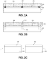
- FIG. 2A illustrates a cross-sectional view of a semiconductor wafer including a plurality of integrated circuits during performing of a method of dicing the semiconductor wafer, corresponding to operation 102 of the Flowchart of FIG. 1 , in accordance with an embodiment of the present invention.
- FIG. 2B illustrates a cross-sectional view of a semiconductor wafer including a plurality of integrated circuits during performing of a method of dicing the semiconductor wafer, corresponding to operation 104 of the Flowchart of FIG. 1 , in accordance with an embodiment of the present invention.
- FIG. 2C illustrates a cross-sectional view of a semiconductor wafer including a plurality of integrated circuits during performing of a method of dicing the semiconductor wafer, corresponding to operation 108 of the Flowchart of FIG. 1 , in accordance with an embodiment of the present invention.
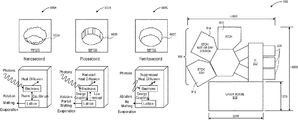
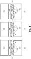
- FIG. 3 illustrates three different scenarios for asymmetric beam splitting, in accordance with an embodiment of the present invention.
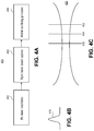
- FIG. 4A is a flowchart representing operations of a laser scribing process with the intensity control of split beams, in accordance with an embodiment of the present invention.
- FIG. 4B illustrates a Gaussian laser beam profile 410 for a laser beam splitting process, in accordance with an embodiment of the present invention.
- FIG. 4C illustrates a Gaussian beam propagation in the beam path 420 , in accordance with an embodiment of the present invention.
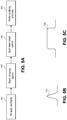
- FIG. 5A is a flowchart representing operations of a laser scribing process with split intensity control of a line shaped beam, in accordance with an embodiment of the present invention.
- FIG. 5B illustrates a Gaussian laser beam profile for a laser beam splitting process, in accordance with an embodiment of the present invention.
- FIG. 5C illustrates a line shaped flat top beam profile, in accordance with an embodiment of the present invention.
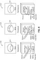
- FIG. 6 illustrates the effects of using a laser pulse width in the femtosecond range, picoseconds range, and nanosecond range, in accordance with an embodiment of the present invention.
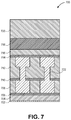
- FIG. 7 illustrates a cross-sectional view of a stack of materials that may be used in a street region of a semiconductor wafer or substrate, in accordance with an embodiment of the present invention.
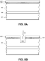
- FIGS. 8A-8D illustrate cross-sectional views of various operations in a method of dicing a semiconductor wafer, in accordance with an embodiment of the present invention.
- FIG. 9 illustrates a block diagram of a tool layout for laser and plasma dicing of wafers or substrates, in accordance with an embodiment of the present invention.
- FIG. 10 illustrates a block diagram of an exemplary computer system, in accordance with an embodiment of the present invention.
- a hybrid wafer or substrate dicing process involving an initial laser scribe and subsequent plasma etch may be implemented for die singulation.
- the laser scribe process may be used to cleanly remove a mask layer, organic and inorganic dielectric layers, and device layers.
- the laser etch process may then be terminated upon exposure of, or partial etch of, the wafer or substrate.
- the plasma etch portion of the dicing process may then be employed to etch through the bulk of the wafer or substrate, such as through bulk single crystalline silicon, to yield die or chip singulation or dicing. More specifically, one or more embodiments are directed to implementing a split shaped laser beam laser scribing process for, e.g., dicing applications.
- advantages for split beam scribing may involve an improved or more efficient use of laser pulse energy.
- high pulse energy tends to ablate relatively large-sized material per pulse.
- the scribed trench is much less clean versus low-energy pulse scribed trenches. This can lead to a more difficult plasma etch process where, for the desired etch quality, much more effect is required to do plasma pre-cleaning of the scribed trench before plasma etching.
- the impact is negative for plasma dicing throughput. In some cases, plasma cleaning may not even make the scribed trench feasible for etch.
- High energy ablation may also cause too deep an ablation than versus what may be desired.
- a femtosecond laser may be applied to remove the mask and device layers on the dicing street until the silicon substrate is exposed.
- a plasma etch follows to separate dies to realize die singulation.
- a Gaussian beam profile is used for the scribing process.
- a Gaussian beam profile shows its limitation with the following two different situations: (1) when a wide kerf is demanded; (2) when a smooth sidewall in combination with high scribing throughput is needed for a typical narrow kerf width.
- the laser intensity control of spatially split beams is implemented for improving laser scribing process in hybrid laser dicing.
- split laser beam control of spatially shaped beams is implemented for improving laser scribing process in hybrid laser dicing processing schemes.
- FIG. 1 is a Flowchart 100 representing operations in a method of dicing a semiconductor wafer including a plurality of integrated circuits, in accordance with an embodiment of the present invention.
- FIGS. 2A-2C illustrate cross-sectional views of a semiconductor wafer including a plurality of integrated circuits during performing of a method of dicing the semiconductor wafer, corresponding to operations of Flowchart 100 , in accordance with an embodiment of the present invention.
- a mask 202 is formed above a semiconductor wafer or substrate 204 .
- the mask 202 is composed of a layer covering and protecting integrated circuits 206 formed on the surface of semiconductor wafer 204 .
- the mask 202 also covers intervening streets 207 formed between each of the integrated circuits 206 .
- forming the mask 202 includes forming a layer such as, but not limited to, a photo-resist layer or an I-line patterning layer.
- a polymer layer such as a photo-resist layer may be composed of a material otherwise suitable for use in a lithographic process.
- the photo-resist layer is composed of a positive photo-resist material such as, but not limited to, a 248 nanometer (nm) resist, a 193 nm resist, a 157 nm resist, an extreme ultra-violet (EUV) resist, or a phenolic resin matrix with a diazonaphthoquinone sensitizer.
- EUV extreme ultra-violet
- the photo-resist layer is composed of a negative photo-resist material such as, but not limited to, poly-cis-isoprene and poly-vinyl-cinnamate.
- forming the mask 202 involves forming a layer deposited in a plasma deposition process.
- the mask 202 is composed of a plasma deposited Teflon or Teflon-like (polymeric CF 2 ) layer.
- the polymeric CF 2 layer is deposited in a plasma deposition process involving the gas C 4 F 8 .
- forming the mask 202 involves forming a water-soluble mask layer.
- the water-soluble mask layer is readily dissolvable in an aqueous media.
- the water-soluble mask layer is composed of a material that is soluble in one or more of an alkaline solution, an acidic solution, or in deionized water.
- the water-soluble mask layer maintains its water solubility upon exposure to a heating process, such as heating approximately in the range of 50-160 degrees Celsius.
- the water-soluble mask layer is soluble in aqueous solutions following exposure to chamber conditions used in a laser and plasma etch singulation process.
- the water-soluble mask layer is composed of a material such as, but not limited to, polyvinyl alcohol, polyacrylic acid, dextran, polymethacrylic acid, polyethylene imine, or polyethylene oxide.
- the water-soluble mask layer has an etch rate in an aqueous solution approximately in the range of 1-15 microns per minute and, more particularly, approximately 1.3 microns per minute.
- forming the mask 202 involves forming a UV-curable mask layer.
- the mask layer has a susceptibility to UV light that reduces an adhesiveness of the UV-curable layer by at least approximately 80%.
- the UV layer is composed of polyvinyl chloride or an acrylic-based material.
- the UV-curable layer is composed of a material or stack of materials with an adhesive property that weakens upon exposure to UV light.
- the UV-curable adhesive film is sensitive to approximately 365 nm UV light. In one such embodiment, this sensitivity enables use of LED light to perform a cure.
- semiconductor wafer or substrate 204 is composed of a material suitable to withstand a fabrication process and upon which semiconductor processing layers may suitably be disposed.
- semiconductor wafer or substrate 204 is composed of a group IV-based material such as, but not limited to, crystalline silicon, germanium or silicon/germanium.
- providing semiconductor wafer 204 includes providing a monocrystalline silicon substrate.
- the monocrystalline silicon substrate is doped with impurity atoms.
- semiconductor wafer or substrate 204 is composed of a III-V material such as, e.g., a III-V material substrate used in the fabrication of light emitting diodes (LEDs).
- LEDs light emitting diodes
- semiconductor wafer or substrate 204 has disposed thereon or therein, as a portion of the integrated circuits 206 , an array of semiconductor devices.
- semiconductor devices include, but are not limited to, memory devices or complimentary metal-oxide-semiconductor (CMOS) transistors fabricated in a silicon substrate and encased in a dielectric layer.
- CMOS complimentary metal-oxide-semiconductor
- a plurality of metal interconnects may be formed above the devices or transistors, and in surrounding dielectric layers, and may be used to electrically couple the devices or transistors to form the integrated circuits 206 .
- Materials making up the streets 207 may be similar to or the same as those materials used to form the integrated circuits 206 .
- streets 207 may be composed of layers of dielectric materials, semiconductor materials, and metallization.
- one or more of the streets 207 includes test devices similar to the actual devices of the integrated circuits 206 .
- the mask 202 is patterned with a split laser beam laser scribing process to provide a patterned mask 208 with gaps 210 , exposing regions of the semiconductor wafer or substrate 204 between the integrated circuits 206 .
- the mask 202 is patterned with a split shaped laser beam laser scribing process to provide the patterned mask 208 with gaps 210 .
- the laser scribing process is used to remove the material of the streets 207 originally formed between the integrated circuits 206 .
- patterning the mask 202 with the split laser beam laser scribing process includes forming trenches 212 partially into the regions of the semiconductor wafer 204 between the integrated circuits 206 , as depicted in FIG. 2B .
- a split laser beam processing scheme may be symmetric in that the beam is split across numerous location at same intensity for each location.
- the beam splitting is asymmetric.
- Such an asymmetric arrangement be used as one of several passes along a wafer used, as a combination, to ultimately scribe the wafer.
- FIG. 3 illustrates three different scenarios for asymmetric beam splitting, in accordance with an embodiment of the present invention.
- part (a) shows a first arrangement of an asymmetric lenslet array where an input laser beam 302 A is passed through a lenslet array 304 A and on to a device wafer 306 A.
- lenslets 308 A increase in size from left to right, allowing increasing beam 310 A intensity from left to right across the device wafer 306 A.
- part (b) shows a second arrangement of an asymmetric lenslet array where an input laser beam 302 B is passed through a lenslet array 304 B and on to a device wafer 306 B.
- lenslets 308 B decrease in size from left to right, allowing decreasing beam 310 B intensity from left to right.
- part (c) shows a third arrangement of an asymmetric lenslet array where an input laser beam 302 C is passed through a lenslet array 304 C and on to a device wafer 306 C.
- lenslets 308 C are varied in size from left to right, allowing varied beam 310 C intensity from left to right.
- FIG. 4A is a flowchart 400 representing operations of a laser scribing process with the intensity control of split beams, in accordance with an embodiment of the present invention.
- a laser beam is input to or generated from a femto-second (Fs) laser oscillator.
- the beam is then passed through split beam optics, such as and including lenslet arrays.
- the output beam is used in a wafer scribing process.
- FIG. 4B illustrates a Gaussian laser beam profile 410 for a laser beam splitting process, in accordance with an embodiment of the present invention.
- the laser beam profile 410 may be a spatial profile of a femtosecond laser.
- FIG. 4C illustrates a Gaussian beam propagation in the beam path 420 , in accordance with an embodiment of the present invention. Referring to FIG. 4C , a first off focus location 422 is shown, a second off focus location 424 is shown, and on focus location 426 is shown.
- a Gaussian beam may be used in a split beam process. However, there may be issued with using such a split beam process, as is shown in FIG. 4C .
- FIG. 5A is a flowchart 500 representing operations of a laser scribing process with split intensity control of a line shaped beam, in accordance with an embodiment of the present invention.
- a laser beam is input to or generated from a femto-second (Fs) laser oscillator.
- the beam is then passed through beam shaping optics.
- the beam is then passed through split beam optics, such as and including lenslet arrays.
- the output beam is used in a wafer scribing process.
- Fs femto-second
- FIG. 5B illustrates a Gaussian laser beam profile 510 for a laser beam splitting process, in accordance with an embodiment of the present invention.
- the laser beam profile 510 may be a spatial profile of a femtosecond laser.
- FIG. 5C illustrates a line shaped flat top beam profile 520 , in accordance with an embodiment of the present invention.
- a laser beam profile 510 is injected onto split laser beam optics to convert the beam from a Gaussian beam profile 510 to a line shaped flat top profile 520 through the beam shaping optics.
- the beam shaping optics includes a diffractive optical element, one or more slit aperture, axicons, etc.
- a scribe process runs at 10 uJ pulse energy, 1 MHz, 1000 mm/sec stage speed, using 2 passes. It takes approximately 11 minutes to scribe an entire wafer. It takes approximately 3 minutes to perform plasma pre-cleaning to enable the final plasma etch.
- workable parameters for a beam splitting application include, in the case of using a one-to-two split beam, the scribe process runs at 800 kHz, 6 uJ pulse energy per split beam (a leading beam and a following beam coaxially aligned to scribe a single line), and 800 mm/sec stage speed, using 1 pass. In one such embodiment, it takes approximately 5 minutes to scribe an entire wafer.
- a femtosecond-based laser is used as a source for a split shaped laser beam scribing process.
- a laser with a wavelength in the visible spectrum plus the ultra-violet (UV) and infra-red (IR) ranges (totaling a broadband optical spectrum) is used to provide a femtosecond-based laser pulse, which has a pulse width on the order of the femtosecond (10 ⁇ 15 seconds).
- ablation is not, or is essentially not, wavelength dependent and is thus suitable for complex films such as films of the mask 202 , the streets 207 and, possibly, a portion of the semiconductor wafer or substrate 204 .
- FIG. 6 illustrates the effects of using a laser pulse width in the femtosecond range, picosecond range, and nanosecond range, in accordance with an embodiment of the present invention.
- heat damage issues are mitigated or eliminated (e.g., minimal to no damage 602 C with femtosecond processing of a via 600 C) versus longer pulse widths (e.g., significant damage 602 A with nanosecond processing of a via 600 A).
- the elimination or mitigation of damage during formation of via 600 C may be due to a lack of low energy recoupling (as is seen for picosecond-based laser ablation of 600 B/ 602 B) or thermal equilibrium (as is seen for nanosecond-based laser ablation), as depicted in FIG. 6 .
- Laser parameters selection may be critical to developing a successful laser scribing and dicing process that minimizes chipping, microcracks and delamination in order to achieve clean laser scribe cuts.
- many functional layers of different material types e.g., conductors, insulators, semiconductors
- thicknesses are typically disposed thereon.
- Such materials may include, but are not limited to, organic materials such as polymers, metals, or inorganic dielectrics such as silicon dioxide and silicon nitride.
- FIG. 7 illustrates a cross-sectional view of a stack of materials that may be used in a street region of a semiconductor wafer or substrate, in accordance with an embodiment of the present invention.
- a street region 700 includes the top portion 702 of a silicon substrate, a first silicon dioxide layer 704 , a first etch stop layer 706 , a first low K dielectric layer 708 (e.g., having a dielectric constant of less than the dielectric constant of 4 . 0 for silicon dioxide), a second etch stop layer 710 , a second low K dielectric layer 712 , a third etch stop layer 714 , an undoped silica glass (USG) layer 716 , a second silicon dioxide layer 718 , and a layer of photo-resist 720 , with relative thicknesses depicted.
- a street region 700 includes the top portion 702 of a silicon substrate, a first silicon dioxide layer 704 , a first etch stop layer 706 , a first low K dielectric layer 708 (e.g., having a dielectric constant of less than the dielectric constant of 4 . 0 for silicon dioxide), a second etch stop layer 710 , a second
- Copper metallization 722 is disposed between the first and third etch stop layers 706 and 714 and through the second etch stop layer 710 .
- the first, second and third etch stop layers 706 , 710 and 714 are composed of silicon nitride, while low K dielectric layers 708 and 712 are composed of a carbon-doped silicon oxide material.
- the materials of street 700 behave quite differently in terms of optical absorption and ablation mechanisms.
- dielectrics layers such as silicon dioxide
- metals, organics (e.g., low K materials) and silicon can couple photons very easily, particularly in response to nanosecond-based irradiation.
- a line shaped profile laser beam laser scribing process is used to pattern a layer of silicon dioxide, a layer of low K material, and a layer of copper by ablating the layer of silicon dioxide prior to ablating the layer of low K material and the layer of copper.
- the split shaped laser beam is a femtosecond-based laser beam
- suitable femtosecond-based laser processes are characterized by a high peak intensity (irradiance) that usually leads to nonlinear interactions in various materials.
- the femtosecond laser sources have a pulse width approximately in the range of 10 femtoseconds to 500 femtoseconds, although preferably in the range of 100 femtoseconds to 400 femtoseconds.
- the femtosecond laser sources have a wavelength approximately in the range of 1570 nanometers to 200 nanometers, although preferably in the range of 540 nanometers to 250 nanometers.
- the laser and corresponding optical system provide a focal spot at the work surface approximately in the range of 3 microns to 15 microns, though preferably approximately in the range of 5 microns to 10 microns or between 10-15 microns.
- the laser source has a pulse repetition rate approximately in the range of 200 kHz to 10 MHz, although preferably approximately in the range of 500 kHz to 5 MHz.
- the laser source delivers pulse energy at the work surface approximately in the range of 0.5 uJ to 100 uJ, although preferably approximately in the range of 1 uJ to 5 uJ.
- the laser scribing process runs along a work piece surface at a speed approximately in the range of 500 mm/sec to 5 m/sec, although preferably approximately in the range of 600 mm/sec to 2 m/sec.
- the scribing process may be run in single pass only, or in multiple passes, but, in an embodiment, preferably 1-2 passes.
- the scribing depth in the work piece is approximately in the range of 5 microns to 50 microns deep, preferably approximately in the range of 10 microns to 20 microns deep.
- the kerf width of the laser beam generated is approximately in the range of 2 microns to 15 microns, although in silicon wafer scribing/dicing preferably approximately in the range of 6 microns to 10 microns, measured at the device/silicon interface.
- Laser parameters may be selected with benefits and advantages such as providing sufficiently high laser intensity to achieve ionization of inorganic dielectrics (e.g., silicon dioxide) and to minimize delamination and chipping caused by underlayer damage prior to direct ablation of inorganic dielectrics. Also, parameters may be selected to provide meaningful process throughput for industrial applications with precisely controlled ablation width (e.g., kerf width) and depth. In an embodiment, a line shaped profile laser beam laser scribing process is suitable to provide such advantages.
- inorganic dielectrics e.g., silicon dioxide
- parameters may be selected to provide meaningful process throughput for industrial applications with precisely controlled ablation width (e.g., kerf width) and depth.
- ablation width e.g., kerf width
- a line shaped profile laser beam laser scribing process is suitable to provide such advantages.
- the dicing or singulation process could be stopped after the above described laser scribing in a case that the laser scribing is used to pattern the mask as well as to scribe fully through the wafer or substrate in order to singulate the dies. Accordingly, further singulation processing would not be required in such a case.
- the following embodiments may be considered in cases where laser scribing alone is not implemented for total singulation.
- the post mask-opening cleaning operation is a plasma-based cleaning process.
- the plasma-based cleaning process is reactive to the regions of the substrate 204 exposed by the gaps 210 .
- the cleaning process itself may form or extend trenches 212 in the substrate 204 since the reactive plasma-based cleaning operation is at least somewhat of an etchant for the substrate 204 .
- the plasma-based cleaning process is non-reactive to the regions of the substrate 204 exposed by the gaps 210 .
- the plasma-based cleaning process is reactive to exposed regions of the substrate 204 in that the exposed regions are partially etched during the cleaning process.
- Ar or another non-reactive gas (or the mix) is combined with SF 6 for a highly-biased plasma treatment for cleaning of scribed openings.
- the plasma treatment using mixed gases Ar+SF 6 under high-bias power is performed for bombarding mask-opened regions to achieve cleaning of the mask-opened regions.
- both physical bombardment from Ar and SF 6 along with chemical etching due to SF 6 and F-ions contribute to cleaning of mask-opened regions.
- the approach may be suitable for photoresist or plasma-deposited Teflon masks 202 , where breakthrough treatment leads to fairly uniform mask thickness reduction and a gentle Si etch. Such a breakthrough etch process, however, may not be best suited for water soluble mask materials.
- the plasma-based cleaning process is non-reactive to exposed regions of the substrate 204 in that the exposed regions are not or only negligible etched during the cleaning process.
- only non-reactive gas plasma cleaning is used.
- Ar or another non-reactive gas (or the mix) is used to perform a highly-biased plasma treatment both for mask condensation and cleaning of scribed openings.
- the approach may be suitable for water-soluble masks or for thinner plasma-deposited Teflon 202 .
- separate mask condensation and scribed trench cleaning operations are used, e.g., an Ar or non-reactive gas (or the mix) highly-biased plasma treatment for mask condensation is first performed, and then an Ar+SF 6 plasma cleaning of a laser scribed trench is performed.
- This embodiment may be suitable for cases where Ar-cleaning is not sufficient for trench cleaning due to too thick of a mask material. Cleaning efficiency is improved for thinner masks, but mask etch rate is much lower, with almost no consumption in a subsequent deep silicon etch process.
- three-operation cleaning is performed: (a) Ar or non-reactive gas (or the mix) highly-biased plasma treatment for mask condensation, (b) Ar+SF 6 highly-biased plasma cleaning of laser scribed trenches, and (c) Ar or non-reactive gas (or the mix) highly-biased plasma treatment for mask condensation.
- a plasma cleaning operation involves first use of a reactive plasma cleaning treatment, such as described above in the first aspect of operation 106 . The reactive plasma cleaning treatment is then followed by a non-reactive plasma cleaning treatment such as described in association with the second aspect of operation 106 .
- etching the semiconductor wafer 204 includes ultimately etching entirely through semiconductor wafer 204 , as depicted in FIG. 2C , by etching the trenches 212 initially formed with the split shaped laser beam laser scribing process.
- patterning the mask with the laser scribing process involves forming trenches in the regions of the semiconductor wafer between the integrated circuits, and plasma etching the semiconductor wafer involves extending the trenches to form corresponding trench extensions.
- each of the trenches has a width
- each of the corresponding trench extensions has the width.
- the resulting roughness of mask opening from laser scribing can impact die sidewall quality resulting from the subsequent formation of a plasma etched trench.
- Lithographically opened masks often have smooth profiles, leading to smooth corresponding sidewalls of a plasma etched trench.
- a conventional laser opened mask can have a very rough profile along a scribing direction if improper laser process parameters are selected (such as spot overlap, leading to rough sidewall of plasma etched trench horizontally).
- the surface roughness can be smoothened by additional plasma processes, there is a cost and throughput hit to remedying such issues. Accordingly, embodiments described herein may be advantageous in providing a smoother scribing process from the laser scribing portion of the singulation process.
- etching the semiconductor wafer 204 includes using a plasma etching process.
- a through-silicon via type etch process is used.
- the etch rate of the material of semiconductor wafer 204 is greater than 25 microns per minute.
- An ultra-high-density plasma source may be used for the plasma etching portion of the die singulation process.
- An example of a process chamber suitable to perform such a plasma etch process is the Applied Centura® SilviaTM Etch system available from Applied Materials of Sunnyvale, Calif., USA.
- the Applied Centura® SilviaTM Etch system combines the capacitive and inductive RF coupling ,which gives much more independent control of the ion density and ion energy than was possible with the capacitive coupling only, even with the improvements provided by magnetic enhancement.
- This combination enables effective decoupling of the ion density from ion energy, so as to achieve relatively high density plasmas without the high, potentially damaging, DC bias levels, even at very low pressures. This results in an exceptionally wide process window.
- any plasma etch chamber capable of etching silicon may be used.
- a deep silicon etch is used to etch a single crystalline silicon substrate or wafer 204 at an etch rate greater than approximately 40% of conventional silicon etch rates while maintaining essentially precise profile control and virtually scallop-free sidewalls.
- a through-silicon via type etch process is used. The etch process is based on a plasma generated from a reactive gas, which generally a fluorine-based gas such as SF 6 , C 4 F 8 , CHF 3 , XeF 2 , or any other reactant gas capable of etching silicon at a relatively fast etch rate.
- the mask layer 208 is removed after the singulation process, as depicted in FIG. 2C .
- the plasma etching operation described in association with FIG. 2C employs a conventional Bosch-type dep/etch/dep process to etch through the substrate 204 .
- a Bosch-type process consists of three sub-operations: deposition, a directional bombardment etch, and isotropic chemical etch which is run through many iterations (cycles) until silicon is etched through.
- wafer dicing may be preformed by initial ablation using a split shaped laser beam laser scribing process to ablate through a mask layer, through wafer streets (including metallization), and partially into a silicon substrate. Die singulation may then be completed by subsequent through-silicon deep plasma etching.
- a specific example of a materials stack for dicing is described below in association with FIGS. 8A-8D , in accordance with an embodiment of the present invention.
- a materials stack for hybrid laser ablation and plasma etch dicing includes a mask layer 802 , a device layer 804 , and a substrate 806 .
- the mask layer, device layer, and substrate are disposed above a die attach film 808 which is affixed to a backing tape 810 .
- the mask layer 802 is a water soluble layer such as the water soluble layers described above in association with mask 202 .
- the device layer 804 includes an inorganic dielectric layer (such as silicon dioxide) disposed above one or more metal layers (such as copper layers) and one or more low K dielectric layers (such as carbon-doped oxide layers).
- the device layer 804 also includes streets arranged between integrated circuits, the streets including the same or similar layers to the integrated circuits.
- the substrate 806 is a bulk single-crystalline silicon substrate.
- the bulk single-crystalline silicon substrate 806 is thinned from the backside prior to being affixed to the die attach film 808 .
- the thinning may be performed by a backside grind process.
- the bulk single-crystalline silicon substrate 806 is thinned to a thickness approximately in the range of 50-100 microns. It is important to note that, in an embodiment, the thinning is performed prior to a laser ablation and plasma etch dicing process.
- the photo-resist layer 802 has a thickness of approximately 5 microns and the device layer 804 has a thickness approximately in the range of 2-3 microns.
- the die attach film 808 (or any suitable substitute capable of bonding a thinned or thin wafer or substrate to the backing tape 810 ) has a thickness of approximately 20 microns.
- the mask 802 , the device layer 804 and a portion of the substrate 806 are patterned with a split shaped laser beam laser scribing process 812 to form trenches 814 in the substrate 806 .
- a through-silicon deep plasma etch process 816 is used to extend the trench 814 down to the die attach film 808 , exposing the top portion of the die attach film 808 and singulating the silicon substrate 806 .
- the device layer 804 is protected by the mask layer 802 during the through-silicon deep plasma etch process 816 .
- the singulation process may further include patterning the die attach film 808 , exposing the top portion of the backing tape 810 and singulating the die attach film 808 .
- the die attach film is singulated by a laser process or by an etch process. Further embodiments may include subsequently removing the singulated portions of substrate 806 (e.g., as individual integrated circuits) from the backing tape 810 . In one embodiment, the singulated die attach film 808 is retained on the back sides of the singulated portions of substrate 806 . Other embodiments may include removing the mask layer 802 from the device layer 804 . In an alternative embodiment, in the case that substrate 806 is thinner than approximately 50 microns, the split shaped laser beam laser scribing process 812 is used to completely singulate substrate 806 without the use of an additional plasma process.
- FIG. 9 illustrates a block diagram of a tool layout for laser and plasma dicing of wafers or substrates, in accordance with an embodiment of the present invention.
- a process tool 900 includes a factory interface 902 (FI) having a plurality of load locks 904 coupled therewith.
- a cluster tool 906 is coupled with the factory interface 902 .
- the cluster tool 906 includes one or more plasma etch chambers, such as plasma etch chamber 908 .
- a laser scribe apparatus 910 is also coupled to the factory interface 902 .
- the overall footprint of the process tool 900 may be, in one embodiment, approximately 3500 millimeters (3.5 meters) by approximately 3800 millimeters (3.8 meters), as depicted in FIG. 9 .
- the laser scribe apparatus 910 houses a laser assembly configured to provide a split laser beam.
- the laser assembly is configured to provide a split shaped laser beam.
- the laser beam is a femto-second based laser beam.
- the laser assembly is configured to provide the split shaped laser beam as a symmetrically split laser beam. In an embodiments, the laser assembly is configured to provide the split shaped laser beam as an asymmetrically split laser beam. In an embodiment, the laser assembly is configured to provide the split shaped laser beam as a line shaped flat top beam profile.
- the laser is suitable for performing a laser ablation portion of a hybrid laser and etch singulation process, such as the laser ablation processes described above.
- a moveable stage is also included in laser scribe apparatus 910 , the moveable stage configured for moving a wafer or substrate (or a carrier thereof) relative to the laser.
- the laser is also moveable.
- the overall footprint of the laser scribe apparatus 910 may be, in one embodiment, approximately 2240 millimeters by approximately 1270 millimeters, as depicted in FIG. 9 .
- the one or more plasma etch chambers 908 is configured for etching a wafer or substrate through the gaps in a patterned mask to singulate a plurality of integrated circuits.
- the one or more plasma etch chambers 908 is configured to perform a deep silicon etch process.
- the one or more plasma etch chambers 808 is an Applied Centura® SilviaTM Etch system, available from Applied Materials of Sunnyvale, Calif., USA.
- the etch chamber may be specifically designed for a deep silicon etch used to create singulate integrated circuits housed on or in single crystalline silicon substrates or wafers.
- a high-density plasma source is included in the plasma etch chamber 908 to facilitate high silicon etch rates.
- more than one etch chamber is included in the cluster tool 906 portion of process tool 900 to enable high manufacturing throughput of the singulation or dicing process.
- the factory interface 902 may be a suitable atmospheric port to interface between an outside manufacturing facility with laser scribe apparatus 910 and cluster tool 906 .
- the factory interface 902 may include robots with arms or blades for transferring wafers (or carriers thereof) from storage units (such as front opening unified pods) into either cluster tool 906 or laser scribe apparatus 910 , or both.
- Cluster tool 906 may include other chambers suitable for performing functions in a method of singulation.
- a deposition chamber 912 in place of an additional etch chamber, is included.
- the deposition chamber 912 may be configured for mask deposition on or above a device layer of a wafer or substrate prior to laser scribing of the wafer or substrate.
- the deposition chamber 912 is suitable for depositing a photo-resist layer.
- a wet/dry station 914 is included in place of an additional etch chamber.
- the wet/dry station may be suitable for cleaning residues and fragments, or for removing a mask, subsequent to a laser scribe and plasma etch singulation process of a substrate or wafer.
- a plasma etch chamber in place of an additional deep silicon etch chamber is included and is configured for performing a plasma-based cleaning process.
- a metrology station is also included as a component of process tool 900 .
- Embodiments of the present invention may be provided as a computer program product, or software, that may include a machine-readable medium having stored thereon instructions, which may be used to program a computer system (or other electronic devices) to perform a process according to embodiments of the present invention.
- the computer system is coupled with process tool 900 described in association with FIG. 9 .
- a machine-readable medium includes any mechanism for storing or transmitting information in a form readable by a machine (e.g., a computer).
- a machine-readable (e.g., computer-readable) medium includes a machine (e.g., a computer) readable storage medium (e.g., read only memory (“ROM”), random access memory (“RAM”), magnetic disk storage media, optical storage media, flash memory devices, etc.), a machine (e.g., computer) readable transmission medium (electrical, optical, acoustical or other form of propagated signals (e.g., infrared signals, digital signals, etc.)), etc.
- FIG. 10 illustrates a diagrammatic representation of a machine in the exemplary form of a computer system 1000 within which a set of instructions, for causing the machine to perform any one or more of the methodologies described herein, may be executed.
- the machine may be connected (e.g., networked) to other machines in a Local Area Network (LAN), an intranet, an extranet, or the Internet.
- LAN Local Area Network
- the machine may operate in the capacity of a server or a client machine in a client-server network environment, or as a peer machine in a peer-to-peer (or distributed) network environment.
- the machine may be a personal computer (PC), a tablet PC, a set-top box (STB), a Personal Digital Assistant (PDA), a cellular telephone, a web appliance, a server, a network router, switch or bridge, or any machine capable of executing a set of instructions (sequential or otherwise) that specify actions to be taken by that machine.
- PC personal computer
- PDA Personal Digital Assistant
- STB set-top box
- WPA Personal Digital Assistant
- the exemplary computer system 1000 includes a processor 1002 , a main memory 1004 (e.g., read-only memory (ROM), flash memory, dynamic random access memory (DRAM) such as synchronous DRAM (SDRAM) or Rambus DRAM (RDRAM), etc.), a static memory 1006 (e.g., flash memory, static random access memory (SRAM), MRAM, etc.), and a secondary memory 1018 (e.g., a data storage device), which communicate with each other via a bus 1030 .
- main memory 1004 e.g., read-only memory (ROM), flash memory, dynamic random access memory (DRAM) such as synchronous DRAM (SDRAM) or Rambus DRAM (RDRAM), etc.
- DRAM dynamic random access memory
- SDRAM synchronous DRAM
- RDRAM Rambus DRAM
- static memory 1006 e.g., flash memory, static random access memory (SRAM), MRAM, etc.
- secondary memory 1018 e.g., a data storage device
- Processor 1002 represents one or more general-purpose processing devices such as a microprocessor, central processing unit, or the like. More particularly, the processor 1002 may be a complex instruction set computing (CISC) microprocessor, reduced instruction set computing (RISC) microprocessor, very long instruction word (VLIW) microprocessor, processor implementing other instruction sets, or processors implementing a combination of instruction sets. Processor 1002 may also be one or more special-purpose processing devices such as an application specific integrated circuit (ASIC), a field programmable gate array (FPGA), a digital signal processor (DSP), network processor, or the like. Processor 1002 is configured to execute the processing logic 1026 for performing the operations described herein.
- ASIC application specific integrated circuit
- FPGA field programmable gate array
- DSP digital signal processor
- the computer system 1000 may further include a network interface device 1008 .
- the computer system 1000 also may include a video display unit 1010 (e.g., a liquid crystal display (LCD), a light emitting diode display (LED), or a cathode ray tube (CRT)), an alphanumeric input device 1012 (e.g., a keyboard), a cursor control device 1014 (e.g., a mouse), and a signal generation device 1016 (e.g., a speaker).
- a video display unit 1010 e.g., a liquid crystal display (LCD), a light emitting diode display (LED), or a cathode ray tube (CRT)
- an alphanumeric input device 1012 e.g., a keyboard
- a cursor control device 1014 e.g., a mouse
- a signal generation device 1016 e.g., a speaker
- the secondary memory 1018 may include a machine-accessible storage medium (or more specifically a computer-readable storage medium) 1032 on which is stored one or more sets of instructions (e.g., software 1022 ) embodying any one or more of the methodologies or functions described herein.
- the software 1022 may also reside, completely or at least partially, within the main memory 1004 and/or within the processor 1002 during execution thereof by the computer system 1000 , the main memory 1004 and the processor 1002 also constituting machine-readable storage media.
- the software 1022 may further be transmitted or received over a network 1020 via the network interface device 1008 .
- machine-accessible storage medium 1032 is shown in an exemplary embodiment to be a single medium, the term “machine-readable storage medium” should be taken to include a single medium or multiple media (e.g., a centralized or distributed database, and/or associated caches and servers) that store the one or more sets of instructions.
- the term “machine-readable storage medium” shall also be taken to include any medium that is capable of storing or encoding a set of instructions for execution by the machine and that cause the machine to perform any one or more of the methodologies of the present invention.
- the term “machine-readable storage medium” shall accordingly be taken to include, but not be limited to, solid-state memories, and optical and magnetic media.
- a machine-accessible storage medium has instructions stored thereon which cause a data processing system to perform a method of dicing a semiconductor wafer having a plurality of integrated circuits.
- the method includes forming a mask above the semiconductor wafer, the mask composed of a layer covering and protecting the integrated circuits.
- the mask is then patterned with a split shaped laser beam laser scribing process to provide a patterned mask with gaps, exposing regions of the semiconductor wafer between the integrated circuits.
- the semiconductor wafer is then plasma etched through the gaps in the patterned mask to singulate the integrated circuits.
Landscapes
- Engineering & Computer Science (AREA)
- Mechanical Engineering (AREA)
- Physics & Mathematics (AREA)
- Optics & Photonics (AREA)
- Plasma & Fusion (AREA)
- General Health & Medical Sciences (AREA)
- Pediatric Medicine (AREA)
- Health & Medical Sciences (AREA)
- Dicing (AREA)
- Laser Beam Processing (AREA)
- Electromagnetism (AREA)
- Drying Of Semiconductors (AREA)
- Closures For Containers (AREA)
Abstract
Description
Claims (7)
Priority Applications (1)
| Application Number | Priority Date | Filing Date | Title |
|---|---|---|---|
| US15/945,966 US11217536B2 (en) | 2016-03-03 | 2018-04-05 | Hybrid wafer dicing approach using a split beam laser scribing process and plasma etch process |
Applications Claiming Priority (2)
| Application Number | Priority Date | Filing Date | Title |
|---|---|---|---|
| US15/060,224 US9972575B2 (en) | 2016-03-03 | 2016-03-03 | Hybrid wafer dicing approach using a split beam laser scribing process and plasma etch process |
| US15/945,966 US11217536B2 (en) | 2016-03-03 | 2018-04-05 | Hybrid wafer dicing approach using a split beam laser scribing process and plasma etch process |
Related Parent Applications (1)
| Application Number | Title | Priority Date | Filing Date |
|---|---|---|---|
| US15/060,224 Division US9972575B2 (en) | 2016-03-03 | 2016-03-03 | Hybrid wafer dicing approach using a split beam laser scribing process and plasma etch process |
Publications (2)
| Publication Number | Publication Date |
|---|---|
| US20180226355A1 US20180226355A1 (en) | 2018-08-09 |
| US11217536B2 true US11217536B2 (en) | 2022-01-04 |
Family
ID=58261525
Family Applications (2)
| Application Number | Title | Priority Date | Filing Date |
|---|---|---|---|
| US15/060,224 Active 2036-03-10 US9972575B2 (en) | 2016-03-03 | 2016-03-03 | Hybrid wafer dicing approach using a split beam laser scribing process and plasma etch process |
| US15/945,966 Expired - Fee Related US11217536B2 (en) | 2016-03-03 | 2018-04-05 | Hybrid wafer dicing approach using a split beam laser scribing process and plasma etch process |
Family Applications Before (1)
| Application Number | Title | Priority Date | Filing Date |
|---|---|---|---|
| US15/060,224 Active 2036-03-10 US9972575B2 (en) | 2016-03-03 | 2016-03-03 | Hybrid wafer dicing approach using a split beam laser scribing process and plasma etch process |
Country Status (8)
| Country | Link |
|---|---|
| US (2) | US9972575B2 (en) |
| EP (1) | EP3214012A1 (en) |
| JP (2) | JP2019512875A (en) |
| KR (1) | KR20180114220A (en) |
| CN (1) | CN108701651B (en) |
| SG (1) | SG11201806838YA (en) |
| TW (2) | TWI731935B (en) |
| WO (1) | WO2017151254A2 (en) |
Families Citing this family (17)
| Publication number | Priority date | Publication date | Assignee | Title |
|---|---|---|---|---|
| US10410924B2 (en) * | 2017-01-12 | 2019-09-10 | Panasonic Intellectual Property Management Co., Ltd. | Manufacturing process of element chip |
| CN108388735B (en) * | 2018-02-28 | 2022-04-22 | 深圳市恒凯微电子科技有限公司 | Method for designing integrated circuit with porous medium layer |
| AU2018203169B1 (en) | 2018-05-07 | 2018-11-08 | B.Box For Kids Developments Pty Ltd | Drinking vessel and ventilation members |
| US10720337B2 (en) * | 2018-07-20 | 2020-07-21 | Asm Ip Holding B.V. | Pre-cleaning for etching of dielectric materials |
| US10720334B2 (en) | 2018-07-20 | 2020-07-21 | Asm Ip Holding B.V. | Selective cyclic dry etching process of dielectric materials using plasma modification |
| US11469141B2 (en) * | 2018-08-07 | 2022-10-11 | Texas Instruments Incorporated | Laser dicing for singulation |
| US11355394B2 (en) * | 2018-09-13 | 2022-06-07 | Applied Materials, Inc. | Wafer dicing using hybrid laser scribing and plasma etch approach with intermediate breakthrough treatment |
| KR102706426B1 (en) | 2018-09-21 | 2024-09-12 | 삼성전자주식회사 | Method of sawing substrate and method of singulating semiconductor chips |
| US11011424B2 (en) * | 2019-08-06 | 2021-05-18 | Applied Materials, Inc. | Hybrid wafer dicing approach using a spatially multi-focused laser beam laser scribing process and plasma etch process |
| US11342226B2 (en) * | 2019-08-13 | 2022-05-24 | Applied Materials, Inc. | Hybrid wafer dicing approach using an actively-focused laser beam laser scribing process and plasma etch process |
| JP7300953B2 (en) * | 2019-09-27 | 2023-06-30 | 株式会社ディスコ | Wafer processing method |
| GB201917988D0 (en) * | 2019-12-09 | 2020-01-22 | Spts Technologies Ltd | A semiconductor wafer dicing process |
| JP7529777B2 (en) * | 2019-12-19 | 2024-08-06 | エーファウ・グループ・エー・タルナー・ゲーエムベーハー | Encapsulated individualized components and methods for producing encapsulated individualized components - Patents.com |
| JP7399565B2 (en) * | 2019-12-23 | 2023-12-18 | 株式会社ディスコ | Processing method of workpiece |
| JP2021136248A (en) * | 2020-02-21 | 2021-09-13 | 株式会社ディスコ | Processing method for device wafer |
| KR102913863B1 (en) * | 2021-04-21 | 2026-01-19 | 주식회사 제우스 | Wafer processing apparatus and wafer processing method |
| DE102022204685B3 (en) * | 2022-05-13 | 2023-10-05 | Fraunhofer-Gesellschaft zur Förderung der angewandten Forschung eingetragener Verein | Optics for generating a linear focus, device and method for machining a workpiece |
Citations (95)
| Publication number | Priority date | Publication date | Assignee | Title |
|---|---|---|---|---|
| US4049944A (en) | 1973-02-28 | 1977-09-20 | Hughes Aircraft Company | Process for fabricating small geometry semiconductive devices including integrated components |
| US4339528A (en) | 1981-05-19 | 1982-07-13 | Rca Corporation | Etching method using a hardened PVA stencil |
| US4684437A (en) | 1985-10-31 | 1987-08-04 | International Business Machines Corporation | Selective metal etching in metal/polymer structures |
| US5336638A (en) | 1991-03-06 | 1994-08-09 | Hitachi, Ltd. | Process for manufacturing semiconductor devices |
| US5593606A (en) | 1994-07-18 | 1997-01-14 | Electro Scientific Industries, Inc. | Ultraviolet laser system and method for forming vias in multi-layered targets |
| JPH09216085A (en) | 1996-02-07 | 1997-08-19 | Canon Inc | Substrate cutting method and cutting device |
| US5691794A (en) | 1993-02-01 | 1997-11-25 | Canon Kabushiki Kaisha | Liquid crystal display device |
| JPH10321908A (en) | 1997-05-19 | 1998-12-04 | Nichia Chem Ind Ltd | Method for manufacturing nitride compound semiconductor device and semiconductor light emitting device |
| US5922224A (en) * | 1996-02-09 | 1999-07-13 | U.S. Philips Corporation | Laser separation of semiconductor elements formed in a wafer of semiconductor material |
| US6028722A (en) * | 1996-03-08 | 2000-02-22 | Sdl, Inc. | Optical beam reconfiguring device and optical handling system for device utilization |
| US6051503A (en) | 1996-08-01 | 2000-04-18 | Surface Technology Systems Limited | Method of surface treatment of semiconductor substrates |
| US6057180A (en) | 1998-06-05 | 2000-05-02 | Electro Scientific Industries, Inc. | Method of severing electrically conductive links with ultraviolet laser output |
| US6174271B1 (en) | 1997-03-09 | 2001-01-16 | Electro Scientific Industries, Inc. | High throughput hole forming system with multiple spindles per station |
| US6211488B1 (en) * | 1998-12-01 | 2001-04-03 | Accudyne Display And Semiconductor Systems, Inc. | Method and apparatus for separating non-metallic substrates utilizing a laser initiated scribe |
| JP2001127011A (en) | 1999-10-26 | 2001-05-11 | Disco Abrasive Syst Ltd | Semiconductor wafer splitting method |
| JP2001144126A (en) | 1999-11-12 | 2001-05-25 | Matsushita Electric Ind Co Ltd | Semiconductor device manufacturing method and semiconductor device |
| US6300593B1 (en) | 1999-12-07 | 2001-10-09 | First Solar, Llc | Apparatus and method for laser scribing a coated substrate |
| US6306731B1 (en) | 1999-10-08 | 2001-10-23 | Oki Electric Industry Co., Ltd. | Semiconductor device and method for fabricating the same |
| US6407363B2 (en) | 2000-03-30 | 2002-06-18 | Electro Scientific Industries, Inc. | Laser system and method for single press micromachining of multilayer workpieces |
| US6426275B1 (en) | 1999-08-03 | 2002-07-30 | Tokyo Seimitsu Co., Ltd. | Method for manufacturing semiconductor chips using protecting pricing and separating sheets |
| US6528864B1 (en) | 1999-11-19 | 2003-03-04 | Disco Corporation | Semiconductor wafer having regular or irregular chip pattern and dicing method for the same |
| WO2003036712A1 (en) | 2001-10-19 | 2003-05-01 | Applied Materials, Inc. | Method and apparatus for dicing a semiconductor wafer |
| US6574250B2 (en) | 2000-01-10 | 2003-06-03 | Electro Scientific Industries, Inc. | Laser system and method for processing a memory link with a burst of laser pulses having ultrashort pulse widths |
| US6582983B1 (en) | 2002-07-12 | 2003-06-24 | Keteca Singapore Singapore | Method and wafer for maintaining ultra clean bonding pads on a wafer |
| JP2003179005A (en) | 2001-12-13 | 2003-06-27 | Tokyo Electron Ltd | Semiconductor device isolation method and semiconductor device isolation device |
| US6593542B2 (en) | 2000-07-12 | 2003-07-15 | Electro Scientific Industries, Inc. | UV laser system and method for single pulse severing of IC fuses |
| WO2003071591A1 (en) | 2002-02-25 | 2003-08-28 | Disco Corporation | Method for dividing semiconductor wafer |
| US20030162313A1 (en) | 2002-02-25 | 2003-08-28 | Samsung Electronics Co., Ltd. | Method for sawing wafer |
| US6676878B2 (en) | 2001-01-31 | 2004-01-13 | Electro Scientific Industries, Inc. | Laser segmented cutting |
| JP2004031526A (en) | 2002-06-24 | 2004-01-29 | Toyoda Gosei Co Ltd | Manufacturing method of group iii nitride compound semiconductor element |
| JP2004055684A (en) | 2002-07-17 | 2004-02-19 | Shinko Electric Ind Co Ltd | Semiconductor device and manufacturing method thereof |
| US6696669B2 (en) | 1996-09-10 | 2004-02-24 | Micron Technology, Inc. | Circuit and method for heating an adhesive to package or rework a semiconductor die |
| US6706998B2 (en) | 2002-01-11 | 2004-03-16 | Electro Scientific Industries, Inc. | Simulated laser spot enlargement |
| US20040080045A1 (en) | 2002-10-28 | 2004-04-29 | Sharp Kabushiki Kaisha | Semiconductor device and chip-stack semiconductor device |
| US6759275B1 (en) | 2001-09-04 | 2004-07-06 | Megic Corporation | Method for making high-performance RF integrated circuits |
| US20040157457A1 (en) | 2003-02-12 | 2004-08-12 | Songlin Xu | Methods of using polymer films to form micro-structures |
| US6803247B2 (en) | 2002-02-28 | 2004-10-12 | Disco Corporation | Method for dividing semiconductor wafer |
| US20040212047A1 (en) | 2003-04-22 | 2004-10-28 | Joshi Subhash M. | Edge arrangements for integrated circuit chips |
| US6887804B2 (en) | 2000-01-10 | 2005-05-03 | Electro Scientific Industries, Inc. | Passivation processing over a memory link |
| JP2005191039A (en) | 2003-12-24 | 2005-07-14 | Matsushita Electric Ind Co Ltd | Semiconductor wafer processing method |
| US6998571B2 (en) | 2003-04-25 | 2006-02-14 | Disco Corporation | Laser beam processing machine |
| US20060043535A1 (en) | 2004-08-24 | 2006-03-02 | Hiatt William M | Pass through via technology for use during the manufacture of a semiconductor device |
| US20060088984A1 (en) | 2004-10-21 | 2006-04-27 | Intel Corporation | Laser ablation method |
| US20060086898A1 (en) | 2004-10-26 | 2006-04-27 | Matsushita Electric Industrial Co., Ltd. | Method and apparatus of making highly repetitive micro-pattern using laser writer |
| US20060146910A1 (en) | 2004-11-23 | 2006-07-06 | Manoochehr Koochesfahani | Method and apparatus for simultaneous velocity and temperature measurements in fluid flow |
| US20060205182A1 (en) | 2005-03-10 | 2006-09-14 | Nec Electronics Corporation | Method for manufacturing semiconductor device |
| US7128806B2 (en) | 2003-10-21 | 2006-10-31 | Applied Materials, Inc. | Mask etch processing apparatus |
| US7129150B2 (en) | 2003-03-11 | 2006-10-31 | Disco Corporation | Method of dividing a semiconductor wafer |
| US7179723B2 (en) | 2003-11-18 | 2007-02-20 | Disco Corporation | Wafer processing method |
| US7265033B2 (en) | 2003-07-02 | 2007-09-04 | Disco Corporation | Laser beam processing method for a semiconductor wafer |
| US7361990B2 (en) | 2005-03-17 | 2008-04-22 | Taiwan Semiconductor Manufacturing Company, Ltd. | Reducing cracking of high-lead or lead-free bumps by matching sizes of contact pads and bump pads |
| US7364986B2 (en) | 2003-09-26 | 2008-04-29 | Disco Corporation | Laser beam processing method and laser beam machine |
| JP2008193034A (en) | 2007-02-08 | 2008-08-21 | Matsushita Electric Ind Co Ltd | Manufacturing method of semiconductor chip |
| US7435607B2 (en) | 2004-01-15 | 2008-10-14 | Disco Corporation | Method of wafer laser processing using a gas permeable protective tape |
| US7459377B2 (en) | 2004-06-08 | 2008-12-02 | Panasonic Corporation | Method for dividing substrate |
| US7468309B2 (en) | 2005-03-29 | 2008-12-23 | Disco Corporation | Semiconductor wafer treatment method |
| US7473866B2 (en) | 2005-07-12 | 2009-01-06 | Disco Corporation | Laser processing apparatus |
| US7507638B2 (en) | 2004-06-30 | 2009-03-24 | Freescale Semiconductor, Inc. | Ultra-thin die and method of fabricating same |
| US7507639B2 (en) | 2005-12-06 | 2009-03-24 | Disco Corporation | Wafer dividing method |
| US20090154518A1 (en) * | 2007-12-17 | 2009-06-18 | Pang H Yang | Laser beam transformer and projector |
| US20090255911A1 (en) | 2008-04-10 | 2009-10-15 | Applied Materials, Inc. | Laser scribing platform and hybrid writing strategy |
| US7629228B2 (en) | 2004-08-02 | 2009-12-08 | Panasonic Corporation | Manufacturing method for semiconductor devices, and formation apparatus for semiconductor wafer dicing masks |
| US20090311830A1 (en) | 2008-06-16 | 2009-12-17 | Samsung Electronics Co., Ltd. | Semiconductor package and manufacturing method thereof |
| US20100013036A1 (en) | 2008-07-16 | 2010-01-21 | Carey James E | Thin Sacrificial Masking Films for Protecting Semiconductors From Pulsed Laser Process |
| US7678670B2 (en) | 2004-12-24 | 2010-03-16 | Panasonic Corporation | TEG removing method in manufacturing method for semiconductor chips |
| US7687740B2 (en) | 2004-06-18 | 2010-03-30 | Electro Scientific Industries, Inc. | Semiconductor structure processing using multiple laterally spaced laser beam spots delivering multiple blows |
| US20100126009A1 (en) | 2008-11-25 | 2010-05-27 | Yonggang Li | Method of enabling selective area plating on a substrate |
| US7754584B2 (en) | 2006-05-12 | 2010-07-13 | Panasonic Corporation | Semiconductor substrate, and semiconductor device and method of manufacturing the semiconductor device |
| US7767551B2 (en) | 2006-10-06 | 2010-08-03 | Panasonic Corporation | Method for fabricating semiconductor chip |
| US7767554B2 (en) | 2007-03-09 | 2010-08-03 | Panasonic Corporation | Method of manufacturing semicondictor chip |
| US7776720B2 (en) | 2002-04-19 | 2010-08-17 | Electro Scientific Industries, Inc. | Program-controlled dicing of a substrate using a pulsed laser |
| US20100216313A1 (en) | 2007-10-12 | 2010-08-26 | Panasonic Corproation | Plasma processing apparatus |
| US7804043B2 (en) | 2004-06-15 | 2010-09-28 | Laserfacturing Inc. | Method and apparatus for dicing of thin and ultra thin semiconductor wafer using ultrafast pulse laser |
| US20100248451A1 (en) | 2009-03-27 | 2010-09-30 | Electro Sceintific Industries, Inc. | Method for Laser Singulation of Chip Scale Packages on Glass Substrates |
| US7838323B2 (en) | 2006-06-09 | 2010-11-23 | Panasonic Corporation | Method for fabricating semiconductor device |
| US7859084B2 (en) | 2008-02-28 | 2010-12-28 | Panasonic Corporation | Semiconductor substrate |
| US20110014777A1 (en) | 2008-03-25 | 2011-01-20 | Hiroshi Haji | Method for processing a substrate, method for manufacturing a semiconductor chip, and method for manufacturing a semiconductor chip having a resin adhesive layer |
| US7875898B2 (en) | 2005-01-24 | 2011-01-25 | Panasonic Corporation | Semiconductor device |
| US7923351B2 (en) | 2005-07-11 | 2011-04-12 | Panasonic Corporation | Manufacturing method of semiconductor devices |
| US7926410B2 (en) | 2007-05-01 | 2011-04-19 | J.R. Automation Technologies, L.L.C. | Hydraulic circuit for synchronized horizontal extension of cylinders |
| US7927973B2 (en) | 2004-10-05 | 2011-04-19 | Panasonic Corporation | Method for dividing semiconductor wafer and manufacturing method for semiconductor devices |
| US20110129958A1 (en) * | 2009-11-30 | 2011-06-02 | Esi-Pyrophotonics Lasers, Inc. | Method and apparatus for scribing a line in a thin film using a series of laser pulses |
| US20110312157A1 (en) | 2010-06-22 | 2011-12-22 | Wei-Sheng Lei | Wafer dicing using femtosecond-based laser and plasma etch |
| US20120002284A1 (en) * | 2010-06-30 | 2012-01-05 | Avago Technologies Fiber Ip (Singapore) Pte. Ltd. | Optical beam splitter for use in an optoelectronic module, and a method for performing optical beam splitting in an optoelectronic module |
| US20120211748A1 (en) | 2011-02-17 | 2012-08-23 | Infineon Technologies Ag | Method of Dicing a Wafer |
| US20120322241A1 (en) | 2011-06-15 | 2012-12-20 | Applied Materials, Inc. | Multi-layer mask for substrate dicing by laser and plasma etch |
| US20120322242A1 (en) * | 2011-06-15 | 2012-12-20 | Applied Materials, Inc. | Multi-step and asymmetrically shaped laser beam scribing |
| US20130017668A1 (en) * | 2011-07-11 | 2013-01-17 | Wei-Sheng Lei | Wafer dicing using hybrid split-beam laser scribing process with plasma etch |
| US20130045554A1 (en) | 2007-08-29 | 2013-02-21 | Semiconductor Energy Laboratory Co., Ltd. | Display device and electronic appliance including the display device |
| US20130065378A1 (en) | 2011-03-14 | 2013-03-14 | Chris Johnson | Method and Apparatus for Plasma Dicing a Semi-conductor Wafer |
| US8759197B2 (en) | 2011-06-15 | 2014-06-24 | Applied Materials, Inc. | Multi-step and asymmetrically shaped laser beam scribing |
| US8883614B1 (en) * | 2013-05-22 | 2014-11-11 | Applied Materials, Inc. | Wafer dicing with wide kerf by laser scribing and plasma etching hybrid approach |
| JP2015519732A (en) | 2012-04-10 | 2015-07-09 | アプライド マテリアルズ インコーポレイテッドApplied Materials,Incorporated | Wafer dicing using hybrid multi-step laser scribing process by plasma etching |
| US20150204491A1 (en) * | 2014-01-21 | 2015-07-23 | Cree, Inc. | Lighting Device Utilizing a Double Fresnel Lens |
| US20150214109A1 (en) | 2014-01-29 | 2015-07-30 | Wei-Sheng Lei | Wafer dicing using hybrid laser scribing and plasma etch approach with mask plasma treatment for improved mask etch resistance |
Family Cites Families (11)
| Publication number | Priority date | Publication date | Assignee | Title |
|---|---|---|---|---|
| US4171060A (en) * | 1978-12-11 | 1979-10-16 | Spil-Les | Covered drinking cup |
| JP2761579B2 (en) * | 1991-02-18 | 1998-06-04 | 株式会社 半導体エネルギー研究所 | Substrate processing equipment |
| JP3612317B2 (en) * | 2001-11-30 | 2005-01-19 | 株式会社東芝 | Manufacturing method of semiconductor device |
| NL1027881C1 (en) * | 2004-05-25 | 2005-11-30 | Swilion B V | Lockable drinking cup. |
| US8912077B2 (en) * | 2011-06-15 | 2014-12-16 | Applied Materials, Inc. | Hybrid laser and plasma etch wafer dicing using substrate carrier |
| US8703581B2 (en) * | 2011-06-15 | 2014-04-22 | Applied Materials, Inc. | Water soluble mask for substrate dicing by laser and plasma etch |
| US9908687B2 (en) * | 2011-11-15 | 2018-03-06 | Ignite Usa, Llc | Travel beverage container |
| US9012305B1 (en) * | 2014-01-29 | 2015-04-21 | Applied Materials, Inc. | Wafer dicing using hybrid laser scribing and plasma etch approach with intermediate non-reactive post mask-opening clean |
| US9610543B2 (en) * | 2014-01-31 | 2017-04-04 | Infineon Technologies Ag | Method for simultaneous structuring and chip singulation |
| US9418894B2 (en) * | 2014-03-21 | 2016-08-16 | Semiconductor Components Industries, Llc | Electronic die singulation method |
| CN104979187A (en) * | 2014-04-02 | 2015-10-14 | 中芯国际集成电路制造(上海)有限公司 | Method for dividing wafer |
-
2016
- 2016-03-03 US US15/060,224 patent/US9972575B2/en active Active
-
2017
- 2017-01-27 WO PCT/US2017/015479 patent/WO2017151254A2/en not_active Ceased
- 2017-01-27 JP JP2018546040A patent/JP2019512875A/en active Pending
- 2017-01-27 SG SG11201806838YA patent/SG11201806838YA/en unknown
- 2017-01-27 CN CN201780014005.1A patent/CN108701651B/en active Active
- 2017-01-27 KR KR1020187028562A patent/KR20180114220A/en not_active Ceased
- 2017-02-21 TW TW106105700A patent/TWI731935B/en active
- 2017-02-21 TW TW110119938A patent/TWI775464B/en active
- 2017-03-03 EP EP17159193.6A patent/EP3214012A1/en not_active Withdrawn
-
2018
- 2018-04-05 US US15/945,966 patent/US11217536B2/en not_active Expired - Fee Related
-
2022
- 2022-09-29 JP JP2022155709A patent/JP2022191302A/en active Pending
Patent Citations (103)
| Publication number | Priority date | Publication date | Assignee | Title |
|---|---|---|---|---|
| US4049944A (en) | 1973-02-28 | 1977-09-20 | Hughes Aircraft Company | Process for fabricating small geometry semiconductive devices including integrated components |
| US4339528A (en) | 1981-05-19 | 1982-07-13 | Rca Corporation | Etching method using a hardened PVA stencil |
| US4684437A (en) | 1985-10-31 | 1987-08-04 | International Business Machines Corporation | Selective metal etching in metal/polymer structures |
| US5336638A (en) | 1991-03-06 | 1994-08-09 | Hitachi, Ltd. | Process for manufacturing semiconductor devices |
| US5691794A (en) | 1993-02-01 | 1997-11-25 | Canon Kabushiki Kaisha | Liquid crystal display device |
| US5593606A (en) | 1994-07-18 | 1997-01-14 | Electro Scientific Industries, Inc. | Ultraviolet laser system and method for forming vias in multi-layered targets |
| JPH09216085A (en) | 1996-02-07 | 1997-08-19 | Canon Inc | Substrate cutting method and cutting device |
| US5922224A (en) * | 1996-02-09 | 1999-07-13 | U.S. Philips Corporation | Laser separation of semiconductor elements formed in a wafer of semiconductor material |
| US6028722A (en) * | 1996-03-08 | 2000-02-22 | Sdl, Inc. | Optical beam reconfiguring device and optical handling system for device utilization |
| US6051503A (en) | 1996-08-01 | 2000-04-18 | Surface Technology Systems Limited | Method of surface treatment of semiconductor substrates |
| US6696669B2 (en) | 1996-09-10 | 2004-02-24 | Micron Technology, Inc. | Circuit and method for heating an adhesive to package or rework a semiconductor die |
| US6174271B1 (en) | 1997-03-09 | 2001-01-16 | Electro Scientific Industries, Inc. | High throughput hole forming system with multiple spindles per station |
| JPH10321908A (en) | 1997-05-19 | 1998-12-04 | Nichia Chem Ind Ltd | Method for manufacturing nitride compound semiconductor device and semiconductor light emitting device |
| US6057180A (en) | 1998-06-05 | 2000-05-02 | Electro Scientific Industries, Inc. | Method of severing electrically conductive links with ultraviolet laser output |
| US6211488B1 (en) * | 1998-12-01 | 2001-04-03 | Accudyne Display And Semiconductor Systems, Inc. | Method and apparatus for separating non-metallic substrates utilizing a laser initiated scribe |
| US6426275B1 (en) | 1999-08-03 | 2002-07-30 | Tokyo Seimitsu Co., Ltd. | Method for manufacturing semiconductor chips using protecting pricing and separating sheets |
| US6306731B1 (en) | 1999-10-08 | 2001-10-23 | Oki Electric Industry Co., Ltd. | Semiconductor device and method for fabricating the same |
| US6465158B1 (en) | 1999-10-26 | 2002-10-15 | Disco Corporation | Semiconductor wafer dividing method |
| JP2001127011A (en) | 1999-10-26 | 2001-05-11 | Disco Abrasive Syst Ltd | Semiconductor wafer splitting method |
| JP2001144126A (en) | 1999-11-12 | 2001-05-25 | Matsushita Electric Ind Co Ltd | Semiconductor device manufacturing method and semiconductor device |
| US6528864B1 (en) | 1999-11-19 | 2003-03-04 | Disco Corporation | Semiconductor wafer having regular or irregular chip pattern and dicing method for the same |
| US6300593B1 (en) | 1999-12-07 | 2001-10-09 | First Solar, Llc | Apparatus and method for laser scribing a coated substrate |
| US6574250B2 (en) | 2000-01-10 | 2003-06-03 | Electro Scientific Industries, Inc. | Laser system and method for processing a memory link with a burst of laser pulses having ultrashort pulse widths |
| US6887804B2 (en) | 2000-01-10 | 2005-05-03 | Electro Scientific Industries, Inc. | Passivation processing over a memory link |
| US6407363B2 (en) | 2000-03-30 | 2002-06-18 | Electro Scientific Industries, Inc. | Laser system and method for single press micromachining of multilayer workpieces |
| US6593542B2 (en) | 2000-07-12 | 2003-07-15 | Electro Scientific Industries, Inc. | UV laser system and method for single pulse severing of IC fuses |
| US6676878B2 (en) | 2001-01-31 | 2004-01-13 | Electro Scientific Industries, Inc. | Laser segmented cutting |
| US6759275B1 (en) | 2001-09-04 | 2004-07-06 | Megic Corporation | Method for making high-performance RF integrated circuits |
| WO2003036712A1 (en) | 2001-10-19 | 2003-05-01 | Applied Materials, Inc. | Method and apparatus for dicing a semiconductor wafer |
| US6642127B2 (en) | 2001-10-19 | 2003-11-04 | Applied Materials, Inc. | Method for dicing a semiconductor wafer |
| JP2003179005A (en) | 2001-12-13 | 2003-06-27 | Tokyo Electron Ltd | Semiconductor device isolation method and semiconductor device isolation device |
| US6706998B2 (en) | 2002-01-11 | 2004-03-16 | Electro Scientific Industries, Inc. | Simulated laser spot enlargement |
| US20040137700A1 (en) | 2002-02-25 | 2004-07-15 | Kazuma Sekiya | Method for dividing semiconductor wafer |
| US20030162313A1 (en) | 2002-02-25 | 2003-08-28 | Samsung Electronics Co., Ltd. | Method for sawing wafer |
| WO2003071591A1 (en) | 2002-02-25 | 2003-08-28 | Disco Corporation | Method for dividing semiconductor wafer |
| US6803247B2 (en) | 2002-02-28 | 2004-10-12 | Disco Corporation | Method for dividing semiconductor wafer |
| US7776720B2 (en) | 2002-04-19 | 2010-08-17 | Electro Scientific Industries, Inc. | Program-controlled dicing of a substrate using a pulsed laser |
| JP2004031526A (en) | 2002-06-24 | 2004-01-29 | Toyoda Gosei Co Ltd | Manufacturing method of group iii nitride compound semiconductor element |
| US6582983B1 (en) | 2002-07-12 | 2003-06-24 | Keteca Singapore Singapore | Method and wafer for maintaining ultra clean bonding pads on a wafer |
| JP2004055684A (en) | 2002-07-17 | 2004-02-19 | Shinko Electric Ind Co Ltd | Semiconductor device and manufacturing method thereof |
| US20040080045A1 (en) | 2002-10-28 | 2004-04-29 | Sharp Kabushiki Kaisha | Semiconductor device and chip-stack semiconductor device |
| US20040157457A1 (en) | 2003-02-12 | 2004-08-12 | Songlin Xu | Methods of using polymer films to form micro-structures |
| US7129150B2 (en) | 2003-03-11 | 2006-10-31 | Disco Corporation | Method of dividing a semiconductor wafer |
| US20040212047A1 (en) | 2003-04-22 | 2004-10-28 | Joshi Subhash M. | Edge arrangements for integrated circuit chips |
| US6998571B2 (en) | 2003-04-25 | 2006-02-14 | Disco Corporation | Laser beam processing machine |
| US7265033B2 (en) | 2003-07-02 | 2007-09-04 | Disco Corporation | Laser beam processing method for a semiconductor wafer |
| US7364986B2 (en) | 2003-09-26 | 2008-04-29 | Disco Corporation | Laser beam processing method and laser beam machine |
| US7128806B2 (en) | 2003-10-21 | 2006-10-31 | Applied Materials, Inc. | Mask etch processing apparatus |
| US7179723B2 (en) | 2003-11-18 | 2007-02-20 | Disco Corporation | Wafer processing method |
| JP2005191039A (en) | 2003-12-24 | 2005-07-14 | Matsushita Electric Ind Co Ltd | Semiconductor wafer processing method |
| US7435607B2 (en) | 2004-01-15 | 2008-10-14 | Disco Corporation | Method of wafer laser processing using a gas permeable protective tape |
| US7459377B2 (en) | 2004-06-08 | 2008-12-02 | Panasonic Corporation | Method for dividing substrate |
| US7804043B2 (en) | 2004-06-15 | 2010-09-28 | Laserfacturing Inc. | Method and apparatus for dicing of thin and ultra thin semiconductor wafer using ultrafast pulse laser |
| US7687740B2 (en) | 2004-06-18 | 2010-03-30 | Electro Scientific Industries, Inc. | Semiconductor structure processing using multiple laterally spaced laser beam spots delivering multiple blows |
| US7507638B2 (en) | 2004-06-30 | 2009-03-24 | Freescale Semiconductor, Inc. | Ultra-thin die and method of fabricating same |
| US7629228B2 (en) | 2004-08-02 | 2009-12-08 | Panasonic Corporation | Manufacturing method for semiconductor devices, and formation apparatus for semiconductor wafer dicing masks |
| US20060043535A1 (en) | 2004-08-24 | 2006-03-02 | Hiatt William M | Pass through via technology for use during the manufacture of a semiconductor device |
| US7927973B2 (en) | 2004-10-05 | 2011-04-19 | Panasonic Corporation | Method for dividing semiconductor wafer and manufacturing method for semiconductor devices |
| US20060088984A1 (en) | 2004-10-21 | 2006-04-27 | Intel Corporation | Laser ablation method |
| US20060086898A1 (en) | 2004-10-26 | 2006-04-27 | Matsushita Electric Industrial Co., Ltd. | Method and apparatus of making highly repetitive micro-pattern using laser writer |
| US20060146910A1 (en) | 2004-11-23 | 2006-07-06 | Manoochehr Koochesfahani | Method and apparatus for simultaneous velocity and temperature measurements in fluid flow |
| US7678670B2 (en) | 2004-12-24 | 2010-03-16 | Panasonic Corporation | TEG removing method in manufacturing method for semiconductor chips |
| US7875898B2 (en) | 2005-01-24 | 2011-01-25 | Panasonic Corporation | Semiconductor device |
| US20060205182A1 (en) | 2005-03-10 | 2006-09-14 | Nec Electronics Corporation | Method for manufacturing semiconductor device |
| US7361990B2 (en) | 2005-03-17 | 2008-04-22 | Taiwan Semiconductor Manufacturing Company, Ltd. | Reducing cracking of high-lead or lead-free bumps by matching sizes of contact pads and bump pads |
| US7468309B2 (en) | 2005-03-29 | 2008-12-23 | Disco Corporation | Semiconductor wafer treatment method |
| US7923351B2 (en) | 2005-07-11 | 2011-04-12 | Panasonic Corporation | Manufacturing method of semiconductor devices |
| US7473866B2 (en) | 2005-07-12 | 2009-01-06 | Disco Corporation | Laser processing apparatus |
| US7507639B2 (en) | 2005-12-06 | 2009-03-24 | Disco Corporation | Wafer dividing method |
| US7754584B2 (en) | 2006-05-12 | 2010-07-13 | Panasonic Corporation | Semiconductor substrate, and semiconductor device and method of manufacturing the semiconductor device |
| US7838323B2 (en) | 2006-06-09 | 2010-11-23 | Panasonic Corporation | Method for fabricating semiconductor device |
| US7767551B2 (en) | 2006-10-06 | 2010-08-03 | Panasonic Corporation | Method for fabricating semiconductor chip |
| US7906410B2 (en) | 2007-02-08 | 2011-03-15 | Panasonic Corporation | Method of manufacturing semiconductor chip using laser light and plasma dicing |
| JP2008193034A (en) | 2007-02-08 | 2008-08-21 | Matsushita Electric Ind Co Ltd | Manufacturing method of semiconductor chip |
| US7767554B2 (en) | 2007-03-09 | 2010-08-03 | Panasonic Corporation | Method of manufacturing semicondictor chip |
| US7926410B2 (en) | 2007-05-01 | 2011-04-19 | J.R. Automation Technologies, L.L.C. | Hydraulic circuit for synchronized horizontal extension of cylinders |
| US20130045554A1 (en) | 2007-08-29 | 2013-02-21 | Semiconductor Energy Laboratory Co., Ltd. | Display device and electronic appliance including the display device |
| US20100216313A1 (en) | 2007-10-12 | 2010-08-26 | Panasonic Corproation | Plasma processing apparatus |
| US20090154518A1 (en) * | 2007-12-17 | 2009-06-18 | Pang H Yang | Laser beam transformer and projector |
| US7859084B2 (en) | 2008-02-28 | 2010-12-28 | Panasonic Corporation | Semiconductor substrate |
| US20110014777A1 (en) | 2008-03-25 | 2011-01-20 | Hiroshi Haji | Method for processing a substrate, method for manufacturing a semiconductor chip, and method for manufacturing a semiconductor chip having a resin adhesive layer |
| US20090255911A1 (en) | 2008-04-10 | 2009-10-15 | Applied Materials, Inc. | Laser scribing platform and hybrid writing strategy |
| US20090311830A1 (en) | 2008-06-16 | 2009-12-17 | Samsung Electronics Co., Ltd. | Semiconductor package and manufacturing method thereof |
| US20100013036A1 (en) | 2008-07-16 | 2010-01-21 | Carey James E | Thin Sacrificial Masking Films for Protecting Semiconductors From Pulsed Laser Process |
| US20100126009A1 (en) | 2008-11-25 | 2010-05-27 | Yonggang Li | Method of enabling selective area plating on a substrate |
| US20100248451A1 (en) | 2009-03-27 | 2010-09-30 | Electro Sceintific Industries, Inc. | Method for Laser Singulation of Chip Scale Packages on Glass Substrates |
| US20110129958A1 (en) * | 2009-11-30 | 2011-06-02 | Esi-Pyrophotonics Lasers, Inc. | Method and apparatus for scribing a line in a thin film using a series of laser pulses |
| US20110312157A1 (en) | 2010-06-22 | 2011-12-22 | Wei-Sheng Lei | Wafer dicing using femtosecond-based laser and plasma etch |
| US20120002284A1 (en) * | 2010-06-30 | 2012-01-05 | Avago Technologies Fiber Ip (Singapore) Pte. Ltd. | Optical beam splitter for use in an optoelectronic module, and a method for performing optical beam splitting in an optoelectronic module |
| US20120211748A1 (en) | 2011-02-17 | 2012-08-23 | Infineon Technologies Ag | Method of Dicing a Wafer |
| US20130065378A1 (en) | 2011-03-14 | 2013-03-14 | Chris Johnson | Method and Apparatus for Plasma Dicing a Semi-conductor Wafer |
| US20130230972A1 (en) | 2011-03-14 | 2013-09-05 | Plasma-Therm Llc | Method and Apparatus for Plasma Dicing a Semi-conductor Wafer |
| JP2014523113A (en) | 2011-06-15 | 2014-09-08 | アプライド マテリアルズ インコーポレイテッド | Multi-step asymmetric laser scribing |
| US20120322241A1 (en) | 2011-06-15 | 2012-12-20 | Applied Materials, Inc. | Multi-layer mask for substrate dicing by laser and plasma etch |
| US20120322242A1 (en) * | 2011-06-15 | 2012-12-20 | Applied Materials, Inc. | Multi-step and asymmetrically shaped laser beam scribing |
| US8557683B2 (en) | 2011-06-15 | 2013-10-15 | Applied Materials, Inc. | Multi-step and asymmetrically shaped laser beam scribing |
| US8759197B2 (en) | 2011-06-15 | 2014-06-24 | Applied Materials, Inc. | Multi-step and asymmetrically shaped laser beam scribing |
| US20130017668A1 (en) * | 2011-07-11 | 2013-01-17 | Wei-Sheng Lei | Wafer dicing using hybrid split-beam laser scribing process with plasma etch |
| JP2014526146A (en) | 2011-07-11 | 2014-10-02 | アプライド マテリアルズ インコーポレイテッド | Wafer dicing using hybrid split beam laser scribing process with plasma etching |
| JP2015519732A (en) | 2012-04-10 | 2015-07-09 | アプライド マテリアルズ インコーポレイテッドApplied Materials,Incorporated | Wafer dicing using hybrid multi-step laser scribing process by plasma etching |
| US8883614B1 (en) * | 2013-05-22 | 2014-11-11 | Applied Materials, Inc. | Wafer dicing with wide kerf by laser scribing and plasma etching hybrid approach |
| US20150204491A1 (en) * | 2014-01-21 | 2015-07-23 | Cree, Inc. | Lighting Device Utilizing a Double Fresnel Lens |
| US20150214109A1 (en) | 2014-01-29 | 2015-07-30 | Wei-Sheng Lei | Wafer dicing using hybrid laser scribing and plasma etch approach with mask plasma treatment for improved mask etch resistance |
Non-Patent Citations (9)
| Title |
|---|
| International Preliminary Report on Patentability from PCT/US2017/015479 dated Sep. 13, 2018, 8 pgs. |
| International Search Report and Written Opinion from PCT/US2017/015479 dated Jun. 19, 2017, 9 pgs. |
| Linder, V. et al., "Water-Soluble Sacrificial Layers for Surface Micromachining," www.small-journal.com, 2005, 1, No. 7, 7 pgs. |
| Non-Final Office Action from U.S. Appl. No. 15/060,224, filed Mar. 3, 2016, dated Jun. 15, 2017, 14 pgs. |
| Notice of Reasons for Rejection from Japanese Patent Application No. 2018-546040 dated Mar. 17, 2021, 9 pgs. |
| Notice of Reasons for Rejection from Japanese Patent Application No. 2018-546040 dated Sep. 22, 2021, 8 pgs. |
| Official Letter from Taiwan Patent Application No. 106105700 dated Sep. 22, 2020, 10 pgs. |
| Official Letter from Taiwan Patent Application No. 110119938 dated Sep. 24, 2021, 10 pgs. |
| Singh, Saravjeet et al., "Apparatus and Methods for Dry Etch With Edge, Side and Back Protection," U.S. Appl. No. 61/491,693, filed May 31, 2011 24 pgs. |
Also Published As
| Publication number | Publication date |
|---|---|
| US9972575B2 (en) | 2018-05-15 |
| TW202141626A (en) | 2021-11-01 |
| JP2022191302A (en) | 2022-12-27 |
| TWI731935B (en) | 2021-07-01 |
| WO2017151254A2 (en) | 2017-09-08 |
| US20170256500A1 (en) | 2017-09-07 |
| CN108701651A (en) | 2018-10-23 |
| CN108701651B (en) | 2023-08-01 |
| SG11201806838YA (en) | 2018-09-27 |
| WO2017151254A3 (en) | 2018-07-26 |
| US20180226355A1 (en) | 2018-08-09 |
| TW201740460A (en) | 2017-11-16 |
| EP3214012A1 (en) | 2017-09-06 |
| KR20180114220A (en) | 2018-10-17 |
| TWI775464B (en) | 2022-08-21 |
| JP2019512875A (en) | 2019-05-16 |
Similar Documents
| Publication | Publication Date | Title |
|---|---|---|
| US11217536B2 (en) | Hybrid wafer dicing approach using a split beam laser scribing process and plasma etch process | |
| US8975163B1 (en) | Laser-dominated laser scribing and plasma etch hybrid wafer dicing | |
| US9852997B2 (en) | Hybrid wafer dicing approach using a rotating beam laser scribing process and plasma etch process | |
| US9349648B2 (en) | Hybrid wafer dicing approach using a rectangular shaped two-dimensional top hat laser beam profile or a linear shaped one-dimensional top hat laser beam profile laser scribing process and plasma etch process | |
| US9018079B1 (en) | Wafer dicing using hybrid laser scribing and plasma etch approach with intermediate reactive post mask-opening clean | |
| US10535561B2 (en) | Hybrid wafer dicing approach using a multiple pass laser scribing process and plasma etch process | |
| US9355907B1 (en) | Hybrid wafer dicing approach using a line shaped laser beam profile laser scribing process and plasma etch process | |
| US9012305B1 (en) | Wafer dicing using hybrid laser scribing and plasma etch approach with intermediate non-reactive post mask-opening clean | |
| US20240079273A1 (en) | Laser scribing trench opening control in wafer dicing using hybrid laser scribing and plasma etch approach | |
| US20210233816A1 (en) | Hybrid wafer dicing approach using a spatially multi-focused laser beam laser scribing process and plasma etch process | |
| US20150243559A1 (en) | Hybrid wafer dicing approach using temporally-controlled laser scribing process and plasma etch | |
| US9245803B1 (en) | Hybrid wafer dicing approach using a bessel beam shaper laser scribing process and plasma etch process | |
| WO2015175268A1 (en) | Hybrid wafer dicing approach using an ultra-short pulsed laguerre gauss beam laser scribing process and plasma etch process | |
| US9196536B1 (en) | Hybrid wafer dicing approach using a phase modulated laser beam profile laser scribing process and plasma etch process | |
| US9281244B1 (en) | Hybrid wafer dicing approach using an adaptive optics-controlled laser scribing process and plasma etch process | |
| US9177861B1 (en) | Hybrid wafer dicing approach using laser scribing process based on an elliptical laser beam profile or a spatio-temporal controlled laser beam profile | |
| EP4014251B1 (en) | Method of and system for dicing a semiconductor wafer ; and method of dicing a semiconductor wafer comprising a plurality of integrated circuits | |
| US20240363412A1 (en) | Hybrid wafer dicing approach using a rectangular laser spot-based laser scribing process and plasma etch process | |
| US20220246476A1 (en) | Hybrid wafer dicing approach using an actively-focused laser beam laser scribing process and plasma etch process | |
| US9330977B1 (en) | Hybrid wafer dicing approach using a galvo scanner and linear stage hybrid motion laser scribing process and plasma etch process |
Legal Events
| Date | Code | Title | Description |
|---|---|---|---|
| FEPP | Fee payment procedure |
Free format text: ENTITY STATUS SET TO UNDISCOUNTED (ORIGINAL EVENT CODE: BIG.); ENTITY STATUS OF PATENT OWNER: LARGE ENTITY |
|
| STPP | Information on status: patent application and granting procedure in general |
Free format text: DOCKETED NEW CASE - READY FOR EXAMINATION |
|
| STPP | Information on status: patent application and granting procedure in general |
Free format text: NON FINAL ACTION MAILED |
|
| STPP | Information on status: patent application and granting procedure in general |
Free format text: NON FINAL ACTION MAILED |
|
| STPP | Information on status: patent application and granting procedure in general |
Free format text: RESPONSE TO NON-FINAL OFFICE ACTION ENTERED AND FORWARDED TO EXAMINER |
|
| STPP | Information on status: patent application and granting procedure in general |
Free format text: FINAL REJECTION MAILED |
|
| AS | Assignment |
Owner name: APPLIED MATERIALS, INC., CALIFORNIA Free format text: ASSIGNMENT OF ASSIGNORS INTEREST;ASSIGNORS:PARK, JUNGRAE;LEI, WEI-SHENG;EATON, BRAD;AND OTHERS;SIGNING DATES FROM 20160309 TO 20160310;REEL/FRAME:057370/0183 |
|
| STPP | Information on status: patent application and granting procedure in general |
Free format text: AWAITING TC RESP., ISSUE FEE NOT PAID |
|
| STPP | Information on status: patent application and granting procedure in general |
Free format text: NOTICE OF ALLOWANCE MAILED -- APPLICATION RECEIVED IN OFFICE OF PUBLICATIONS |
|
| STPP | Information on status: patent application and granting procedure in general |
Free format text: AWAITING TC RESP., ISSUE FEE NOT PAID |
|
| STPP | Information on status: patent application and granting procedure in general |
Free format text: AWAITING TC RESP., ISSUE FEE NOT PAID |
|
| STPP | Information on status: patent application and granting procedure in general |
Free format text: AWAITING TC RESP, ISSUE FEE PAYMENT RECEIVED |
|
| STPP | Information on status: patent application and granting procedure in general |
Free format text: AWAITING TC RESP, ISSUE FEE PAYMENT VERIFIED |
|
| STPP | Information on status: patent application and granting procedure in general |
Free format text: PUBLICATIONS -- ISSUE FEE PAYMENT VERIFIED |
|
| STCF | Information on status: patent grant |
Free format text: PATENTED CASE |
|
| FEPP | Fee payment procedure |
Free format text: MAINTENANCE FEE REMINDER MAILED (ORIGINAL EVENT CODE: REM.); ENTITY STATUS OF PATENT OWNER: LARGE ENTITY |
|
| LAPS | Lapse for failure to pay maintenance fees |
Free format text: PATENT EXPIRED FOR FAILURE TO PAY MAINTENANCE FEES (ORIGINAL EVENT CODE: EXP.); ENTITY STATUS OF PATENT OWNER: LARGE ENTITY |
|
| STCH | Information on status: patent discontinuation |
Free format text: PATENT EXPIRED DUE TO NONPAYMENT OF MAINTENANCE FEES UNDER 37 CFR 1.362 |
|
| FP | Lapsed due to failure to pay maintenance fee |
Effective date: 20260104 |