US11216093B2 - Systems, apparatus, and methods for detecting computing device inputs by a pointing body - Google Patents
Systems, apparatus, and methods for detecting computing device inputs by a pointing body Download PDFInfo
- Publication number
- US11216093B2 US11216093B2 US17/004,924 US202017004924A US11216093B2 US 11216093 B2 US11216093 B2 US 11216093B2 US 202017004924 A US202017004924 A US 202017004924A US 11216093 B2 US11216093 B2 US 11216093B2
- Authority
- US
- United States
- Prior art keywords
- threshold
- make
- break
- event
- pressure value
- Prior art date
- Legal status (The legal status is an assumption and is not a legal conclusion. Google has not performed a legal analysis and makes no representation as to the accuracy of the status listed.)
- Active
Links
Images


Classifications
-
- G—PHYSICS
- G06—COMPUTING; CALCULATING OR COUNTING
- G06F—ELECTRIC DIGITAL DATA PROCESSING
- G06F3/00—Input arrangements for transferring data to be processed into a form capable of being handled by the computer; Output arrangements for transferring data from processing unit to output unit, e.g. interface arrangements
- G06F3/01—Input arrangements or combined input and output arrangements for interaction between user and computer
- G06F3/03—Arrangements for converting the position or the displacement of a member into a coded form
- G06F3/041—Digitisers, e.g. for touch screens or touch pads, characterised by the transducing means
-
- G—PHYSICS
- G06—COMPUTING; CALCULATING OR COUNTING
- G06F—ELECTRIC DIGITAL DATA PROCESSING
- G06F3/00—Input arrangements for transferring data to be processed into a form capable of being handled by the computer; Output arrangements for transferring data from processing unit to output unit, e.g. interface arrangements
- G06F3/01—Input arrangements or combined input and output arrangements for interaction between user and computer
- G06F3/016—Input arrangements with force or tactile feedback as computer generated output to the user
-
- G—PHYSICS
- G06—COMPUTING; CALCULATING OR COUNTING
- G06F—ELECTRIC DIGITAL DATA PROCESSING
- G06F2203/00—Indexing scheme relating to G06F3/00 - G06F3/048
- G06F2203/041—Indexing scheme relating to G06F3/041 - G06F3/045
- G06F2203/04105—Pressure sensors for measuring the pressure or force exerted on the touch surface without providing the touch position
Definitions
- the subject matter disclosed herein relates to computing systems and devices and, more particularly, relates to systems, apparatus, and methods for detecting computing device inputs by a pointing body.
- Conventional input devices e.g., a touch screen of a tablet terminal, a flat type keyboard without key traveling, or a touch-type operation switch without keystroke
- an actuator built into the input device.
- the actuator is driven in response to a user's input operation to give the user a tactile feedback (e.g., haptic feedback).
- Japanese Patent Application Publication No. 2011-48409 discloses an input device configured to vibrate a touch surface of a touch sensor to give an operator a click feeling upon detecting a pressure load on the touch sensor that satisfies a first condition.
- the touch surface of the touch sensor also vibrates to give the operator a release feeling from the click feeling upon detecting that the pressure load on the touch sensor satisfies a second condition.
- a multi-click operation e.g., a double-click operation, a triple-click operation, or the like operation
- multiple clicks are continuously input, as one of the operations.
- users can become fatigued having to perform one or more multi-click operations.
- One system includes a pressure sensor configured to detect a set of physical touches indicating a pressed state of a pointing body on an operation surface of a computing device and a controller configured to detect inputs of the pointing body based on the set of physical touches indicating the pressed state detected by the pressure sensor.
- the controller includes a make event detector configured to detect a make event including a first physical touch including a first pressure value that is greater than or equal to a make threshold pressure value based on the detected user inputs and the make event detector utilizes a first threshold as the make threshold for use in detecting a first round of the make event and utilizing a second threshold, which is less than the first threshold, as the make threshold for use in detecting subsequent rounds of the make event within a first predetermined multi-click detection period of time.
- An apparatus includes a processor of an information handling device and a memory configured to store code executable by the processor.
- the executable code causes the processor to detect user inputs based on a received set of physical touches of a pointing body pressing an operation surface of a computing device indicating a pressed state of the operation surface detected by a pressure sensor, detect a make event comprising a first physical touch including a first pressure value that is greater than or equal to a make threshold pressure value based on the detected user inputs, and utilize a first threshold as the make threshold for use in detecting a first round of the make event and a second threshold, which is less than the first threshold, as the make threshold for use in detecting subsequent rounds of the make event within a first predetermined multi-click detection period of time.
- One method includes detecting, by an information handling device, user inputs based on a received set of physical touches of a pointing body pressing an operation surface of a computing device indicating a pressed state of the operation surface detected by a pressure sensor, detecting a make event comprising a first physical touch including a first pressure value that is greater than or equal to a make threshold pressure value based on the detected user inputs, and utilizing a first threshold as the make threshold for use in detecting a first round of the make event and a second threshold, which is less than the first threshold, as the make threshold for use in detecting subsequent rounds of the make event within a first predetermined multi-click detection period of.
- FIG. 1 is a schematic diagram illustrating an external view of one embodiment of a laptop personal computer (e.g., an information handling device);
- a laptop personal computer e.g., an information handling device
- FIG. 2 is a block diagram illustrating a vertical cross-section of one embodiment of a main body chassis and a touchpad in the laptop personal computer (PC) of FIG. 1 ;
- FIG. 3 is a schematic block diagram illustrating one embodiment of a hardware configuration of the laptop PC of FIG. 1 ;
- FIG. 4 is diagram illustrating one embodiment of a functional configuration related to an input detection function of the laptop PC of FIG. 1 ;
- FIG. 5 is a flowchart diagram illustrating one embodiment of a method for detecting inputs to a laptop PC (e.g., an information handling device);
- a laptop PC e.g., an information handling device
- FIG. 6 is a flowchart diagram illustrating one embodiment of a method for performing a threshold change process
- FIG. 7 is a timing diagram describing one embodiment of a threshold change process and detection timings of a make event and a break event
- FIG. 8 is a timing diagram illustrating another embodiment of a threshold timing change in a threshold change process
- FIG. 9 is a timing diagram illustrating yet another embodiment of a threshold timing change in a threshold change process.
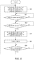
- FIG. 10 is a flowchart diagram illustrating another embodiment of a method for performing a threshold change process
- FIG. 11 is a timing diagram describing another embodiment of a threshold change process and detection timings of a make event and a break event.
- embodiments may be embodied as an apparatus and/or a system. Accordingly, embodiments may take the form of an entirely hardware embodiment or an embodiment combining hardware and software aspects that may all generally be referred to herein as a “circuit,” “module” or “system.”
- the various embodiments disclosed herein provide an input device and an input detection method thereof capable of reducing the feeling of fatigue experienced by a user when a multi-click operation is performed.
- An input device includes a pressure sensor configured to detect a physical quantity of touches indicating a pressed state of a pointing device on an operational surface and a controller configured to detect an input on the basis of a physical quantity of touches indicating the pressed state detected by the pressure sensor.
- the controller includes a make event detector configured to detect a make event in the case where the physical quantity of touches is greater than or equal to a threshold quantity of touches and the make event detector uses a first threshold of touches as a make threshold for use in detecting a first round of a make event and uses a second threshold of touches, which is smaller than the first threshold of touches, as another make threshold for use in detecting second and subsequent rounds of make events in the case of detecting a plurality of make events within a predetermined multi-click detection period.
- An information processing apparatus includes the above-described input device.
- An input detection method which is intended for an input device configured to include a pressure sensor that detects a physical quantity of touches indicating a pressed state of a pointing device on an operational surface, includes a computing device (e.g., an information handling device) detecting a make event in response to a physical quantity of touches being greater than or equal to a make threshold of touches.
- the computer uses a first threshold of touches as a make threshold for use in detecting a first round of a make event and uses a second threshold of touches, which is smaller than the first threshold of touches, as a second make threshold for use in detecting second and subsequent rounds of make events in the case of detecting a plurality of make events within a predetermined multi-click detection period of time.
- Input devices and input detection methods thereof are described below with reference to the appended drawing figures.
- a laptop personal computer which can be considered an information processing apparatus and/or an information handling device
- the various embodiments are not limited tom laptop PCs. That is, the input device(s) and the input detection method(s) can be applied to other computing devices that provide a human-machine interface and/or interaction.
- an input device is not limited thereto, and any input device may be used provided that the input device includes a multi-click function as an input operation.
- a pressure-sensitive touch display may be used as the input device.
- FIG. 1 is a schematic diagram illustrating an external view of one embodiment of a laptop PC 1 .
- the laptop PC 1 includes, among other components, a display side chassis 2 A and a main body side chassis 2 B, both of which include a substantially rectangular shape.
- the display side chassis 2 A includes a display 4 configured to display images.
- the display side chassis 2 A and the main body side chassis 2 B are connected, for example, by a pair of left and right connecting parts 3 A and 3 B at their respective ends.
- the connecting parts 3 A and 3 B include hinges, which support the display side chassis 2 A and the main body side chassis 2 B so that the display side chassis 2 A and the main body side chassis 2 B can be opened and closed.
- the main body side chassis 2 B includes, among other components, a flat keyboard 5 and a pressure-sensitive touchpad 6 as input devices.
- a keyboard is not limited to the flat keyboard 5 exemplified in this embodiment and may include a keyboard device including multiple physical keys arranged so that the physical keys can move down and up when pressed/depressed.
- the flat keyboard 5 in some embodiments, includes a panel with a touch sensor 27 (see, FIG. 3 ) that displays images indicating a plurality of key positions in which inputs of characters, commands, or the like are accepted.
- the flat keyboard 5 is configured to have no or little, if any, keystrokes.
- the pressure-sensitive touchpad 6 includes an area for performing pointing and tapping operations (e.g., a click operation, a double-click operation, a triple-click operation, and the like operation(s)) to move a pointer 7 displayed on the display 4 .
- the pressure-sensitive touchpad 6 illustrated in FIG. 1 is displayed in a rectangular shape, but the shape is not limited thereto, and other shapes may be used.
- the pressure-sensitive touchpad 6 is provided on the lower side (e.g., a user side) of the flat keyboard 5 on the surface of the main body side chassis 2 B; however, the location is not limited thereto.
- the pressure-sensitive touchpad 6 may be provided on the right or left side of the flat keyboard 5 .
- the pressure-sensitive touchpad 6 is configured to have no or little, if any, keystrokes similar to the flat keyboard 5 .
- FIG. 2 is a schematic diagram of a vertical cross-section of one embodiment of the main body side chassis 2 B including the pressure-sensitive touchpad 6 .
- the pressure-sensitive touchpad 6 includes a pressure sensor 33 provided on the back of the operation surface (e.g., a chassis surface) and a haptic device 34 provided on an underside of the pressure sensor 33 .
- the haptic device 34 includes a feedback unit and/or device that provides feedback (hereinafter, referred to as “haptic feedback”) to the tactile sensation of a user's finger or the like and is equipped with, for example, an actuator 34 A that causes vibration.
- the actuator 34 A in configured to transmit the vibration(s) to the pressure-sensitive touchpad 6 in response to a user's input to the pressure-sensitive touchpad 6 .
- the user perceives the vibration(s) with his/her finger, which gives the user the illusion, sensation, and/or impression that the user has actually pressed the pressure-sensitive touchpad 6 .
- the actuator 34 A is configured to provide vibration of a constant or substantially constant amplitude to a vibrating body 34 B for a predetermined amount of time.
- the actuator 34 A may include, for example, an eccentric rotating mass (ERM) actuator that uses an eccentric motor, a linear resonant actuator (LRA) that vibrates a mover by applying an alternating current to a coil in a magnetic field, an actuator using a shape memory alloy (e.g., a shape memory alloy impact actuator (SIA)), and an actuator using a piezoelectric element (e.g., a piezo element, a piezo vibration actuator (PVA), etc.), among other actuators that are possible and contemplated herein.
- a shape memory alloy e.g., a shape memory alloy impact actuator (SIA)
- SIA shape memory alloy impact actuator
- PVA piezo vibration actuator
- the quantity of installed haptic devices 34 and their respective locations are not limited to this embodiment.
- a plurality of haptic devices 34 may be provided.
- the haptic devices 34 may be provided with one haptic device 34 located at each of the four corners inside the main body side chassis 2 B.
- FIG. 3 is a diagram illustrating one embodiment of a hardware configuration of a laptop PC 1 .
- the laptop PC 1 includes, among other components, a central processing unit (CPU) 20 , a read-only memory (ROM) 21 , a memory 22 , a flash memory 30 , a communication device 31 , a power supply circuit 32 , and the like components, and the respective units are connected directly or indirectly via a bus 36 .
- the display 4 is configured to include, among other components, a liquid crystal display (LCD) 23 and a graphics adapter 24 .
- the graphics adapter 24 is configured to convert image information/data to a video signal and output the converted video signal to the LCD 23 .
- the LCD 23 displays the video signal received from the graphics adapter 24 as an image under the control of the CPU 20 .
- the flat keyboard 5 is configured to include, among other components, a touch sensor 27 and/or a touch IC 28 .
- the touch sensor 27 is configured to detect, for example, a physical quantity of touches indicating the pressed state of a user's finger or the like on the flat keyboard 5 and output a detection signal related to a pressed position and a pressed state to the touch IC 28 .
- the touch sensor 27 may include, for example, a capacitance type, a resistance film type, or an electromagnetic induction type of touch sensor, among other types of touch sensors that are possible and contemplated herein.
- the touch IC 28 is configured to perform various processes based on the detection signal input from the touch sensor 27 via a processor executing a program stored in the ROM 21 or the like memory device(s).
- the pressure-sensitive touchpad 6 is configured to include, among other components, a pressure sensor 33 , a haptic device 34 , and a pad controller 35 .
- the pressure sensor 33 is configured to detect a physical quantity of touches indicating the pressed state of a user's finger (e.g., a pointing body) on the operation surface (e.g., a chassis surface) of the pressure-sensitive touchpad 6 and output a detection signal related to the physical quantity of touches to the pad controller (e.g., a controller) 35 .
- the pressure sensor 33 is further configured to detect, for example, a pressure value corresponding to the pressed state of a user's finger or the like.
- the pressure sensor 33 is configured to detect a contact pressure (e.g., click-down pressure) on the operation surface and then output a detection signal related to the detected pressure value to the pad controller 35 .
- the pad controller 35 includes a processor.
- the processor is configured to execute a set of programs stored in the ROM 21 , the flash memory 30 , or the like memory device(s) to perform various processes based on a detection signal input from the pressure sensor 33 .
- the pad controller 35 is configured to receive the detection signal from the pressure sensor 33 and, in response thereto, output a signal for driving the haptic device 34 to the haptic device 34 .
- the CPU 20 is configured to control the laptop PC 1 via an operating system (OS) stored in the flash memory 30 that is connected and/coupled to the CPU 20 via the bus 36 . Further, the CPU 20 is configured to perform a set of processes based on information/data from the input device (e.g., the flat keyboard 5 and/or the pressure-sensitive touchpad 6 ) on the basis of various programs stored in the flash memory 30 .
- OS operating system
- the input device e.g., the flat keyboard 5 and/or the pressure-sensitive touchpad 6
- the ROM 21 stores a basic input/output system (BIOS), various data, and the like.
- the memory 22 includes, among other components, a cache memory and/or a random-access memory (RAM).
- the memory 22 further includes a writable memory used as a work area for reading an execution program of the CPU 20 and writing processing data by the execution program.
- the flash memory 30 stores, among other data, a multi-window OS for controlling the laptop PC 1 , various drivers for operating hardware of peripheral devices, utility programs, various application programs, and the like.
- the laptop PC 1 may include another storage section, such as a hard disk drive (HDD), as a storage section and/or device that is in addition or an alternative to the flash memory 30 .
- HDD hard disk drive
- the communication device 31 is configured to communicate with one or more other devices.
- the power supply circuit 32 includes an Alternating Current (AC) adapter, a battery, a charger for charging the battery, and a Direct Current-to-Direct Current (DC-DC) converter or the like and is configured to supply electric power to the respective devices under the control of the CPU 20 .
- AC Alternating Current
- DC-DC Direct Current-to-Direct Current
- FIG. 4 is a functional configuration diagram schematically illustrating one embodiment of a functional configuration related to an input detection function of the laptop PC.
- the processes for implementing various functions described below are stored in a computer-readable recording medium (e.g., a non-transitory computer-readable storage medium) in the form of a program.
- the program is read to the memory 22 , such as the RAM, and is executed by a processor mounted at least on the pad controller 35 or on the CPU 20 , in which various functions are implemented.
- the program may be previously installed in the ROM 21 , the flash memory 30 , or other storage media, and may be provided in the state of being stored in a computer-readable storage medium or may be distributed through a wired or wireless communication section.
- the computer-readable storage medium may include a magnetic disk, a magneto-optical disk, a CD-ROM, a DVD-ROM, a semiconductor memory, or the like.
- the various embodiments are not limited thereto.
- at least one processor included in the laptop PC 1 executes a predetermined program (e.g., an input detection program) to implement the various functions disclosed below. That is, the following various functions may be implemented by the cooperation of the pad controller 35 and the CPU 20 or the following functions may be implemented by the cooperation of the pad controller 35 and one or more other processors.
- the pad controller 35 includes, among other components, a make event detector 40 , a break event detector 41 , a feedback controller 42 , and a threshold change unit 43 . Additionally, the pad controller 35 is configured to output an input signal corresponding to the user's input operation to the CPU 20 .
- the make event detector 40 is configured to determine and/or detect a make event, which includes an event at the time when a user's finger (e.g., pointing body) presses the pressure-sensitive touchpad 6 and a pressure value is detected by the pressure sensor 33 .
- the make event detector 40 is configured to detect a make event in situations in which the pressure value from the pressure sensor 33 is greater than or equal to a make threshold pressure value.
- the break event detector 41 is configured to determine and/or detect a break event, which includes an event at the time when a user's finger is separated from the pressure-sensitive touchpad 6 and a pressure value is detected by the pressure sensor 33 . Specifically, after the make event is detected, the break event detector 41 detects a break event in which the pressure value from the pressure sensor 33 is less than or equal to a break threshold pressure value, which is a pressure value less than or equal to the make threshold pressure value.
- the make threshold and the break threshold pressure values are parameters that can be set and/or changed by the threshold change unit 43 , the details of which are discussed elsewhere herein.
- the feedback controller 42 is configured to activate the haptic device 34 according to a make event and/or a break event.
- the time when the haptic device 34 vibrates is set to be an appropriate amount of time for a user to feel/sense the click. Note that the haptic device 34 may be activated in response to a make event.
- the threshold change unit 43 is configured to set and/or change the make threshold pressure value, which is used by the make event detector 40 , and the break threshold pressure value, which is used by the break event detector 41 .
- the threshold change unit 43 includes an initial pressure value (e.g., Pm 1 ) for the make threshold pressure value and an initial pressure value (e.g., Pb 1 ) for the break threshold pressure value.
- Pm 1 initial pressure value
- Pb 1 initial pressure value
- the threshold change unit 43 sets the initial make pressure value Pm 1 as the make threshold pressure value and sets the initial break threshold pressure value Pb 1 as the break threshold pressure value, which is less than Pm 1 (Pm 1 ⁇ Pb 1 ).
- the threshold change unit 43 is configured to lower the make threshold pressure value in response to detecting a break event. For example, in response to detecting a break event, the threshold change unit 43 changes the make threshold pressure value to a changed make threshold pressure value Pm 2 (e.g., a second make threshold pressure value) that is set to a value of a predetermined amount that is smaller than the initial value Pm 1 (e.g., a first make threshold pressure value).
- a changed make threshold pressure value Pm 2 e.g., a second make threshold pressure value
- the threshold change unit 43 changes the make threshold pressure value from the changed make threshold pressure value Pm 2 to the initial make threshold pressure value Pm 1 and changes the lowered make threshold pressure value to the original make threshold pressure value.
- the make threshold pressure value used to detect second and subsequent rounds of make events is set to a make threshold pressure value that is lower than the make threshold pressure value used to detect a first round of a make event.
- the threshold change unit 43 may also lower the break threshold pressure value in conjunction with the lowering of the make threshold pressure value.
- the threshold change unit 43 can change the break threshold pressure value to the changed break threshold pressure value Pb 2 , which is set to a value a predetermined amount smaller than the initial break threshold pressure value Pb 1 , in conjunction with the lowering of the make threshold pressure value.
- the threshold change unit 43 may change the break threshold pressure value to the initial break threshold pressure value Pb 1 , which is the original threshold pressure value, in tandem with changing the above-described make threshold pressure value to the initial make threshold pressure value Pm 1 , which is the original make threshold pressure value.
- the break threshold pressure value used to detect second and subsequent rounds of break events will also be set to a value lower than the break threshold pressure value used to detect a first round of a break event.
- the threshold change unit 43 reducing the make threshold pressure value and the break threshold pressure value in response to detecting a break event. Further, in response to reducing the make threshold pressure value and the break threshold pressure value, the threshold change unit 43 changes the make threshold pressure value and the break threshold pressure value to the original threshold pressure values (e.g., the initial make and break threshold pressure values) when a preset threshold change period has elapsed from the detection of the break event.
- the original threshold pressure values e.g., the initial make and break threshold pressure values
- the initial make threshold pressure value Pm 1 and the changed make threshold pressure value Pm 2 and the corresponding initial break threshold pressure value Pb 1 and the changed break threshold pressure value Pb 2 can be appropriately set according to the size, shape, material, or main usage of the pressure-sensitive touchpad 6 and/or the information processing apparatus (e.g., laptop PC 1 ) to which the various embodiments disclosed herein are applied. Moreover, since there is an individual difference in the pressure value depending on the user, the pressure values in past uses of the laptop PC 1 may be recorded/stored for each user so that initially set make and break threshold pressure values can be automatically corrected and set on the basis of the past use or uses.
- FIG. 5 is a flowchart diagram illustrating one embodiment of a method for an input detection process.
- FIG. 6 is a flowchart diagram illustrating one embodiment of a method for a threshold change process, which can be performed in parallel with the method discussed with reference to FIG. 5 .
- the input detection method will be described with reference to FIG. 5 and then the threshold pressure value change method will be described with reference to FIG. 6 .
- the input detection method discussed with reference to FIG. 5 starts with the booting of the laptop PC 1 as a trigger, for example.
- the pressure sensor 33 determines whether the pressure value detected by the pressure sensor 33 is greater than or equal to the make threshold pressure value (block SA 2 ).
- the pressure sensor 33 determines that the detected contact is not intended for a user's click operation, and the process returns to block SA 1 .
- the pressure value detected by the pressure sensor 33 being greater than or equal to the make threshold pressure value (e.g., a “YES” in block SA 2 )
- a make event is detected (block SA 3 ) and a signal that drives the haptic device 34 is output upon the detection of the make event (block SA 4 ).
- the pressure sensor 33 determines whether a subsequent pressure value detected by the pressure sensor 33 is less than or equal to the break threshold pressure value (block SA 5 ). In response to the pressure sensor 33 determining that the subsequent pressure value detected by the pressure sensor 33 is not less than or equal to the break threshold pressure value (e.g., a “NO” in block SA 5 ), the touching pointing body (e.g., a user's finger) is not separated from the touch pad, the determination process of block SA 6 is repeated until the pressure value decreases to the break threshold pressure value or less.
- the break threshold pressure value e.g., a “NO” in block SA 5
- a break event is detected (block SA 6 )
- a signal for driving the haptic device is output upon the detection of this break event (block SA 7 )
- the process returns to block SA 1 described above.
- the threshold change method illustrated in FIG. 6 starts with the booting of the laptop PC 1 as a trigger, for example. First, the initial make threshold pressure value Pm 1 is set and the initial break threshold pressure value Pb 1 is set (block SB 1 ).
- a pressure sensor 33 determines whether a break event has occurred (block SB 2 ), which corresponds to detecting a break event in block SA 6 of the user feedback process illustrated in FIG. 5 . In response to not detecting a break event (e.g., a “NO” in block SB 2 ), the pressure sensor 33 continues to determine whether a break event has occurred in block SB 2 .
- a break event e.g., a “NO” in block SB 2
- the pressure sensor 33 continues to determine whether a break event has occurred in block SB 2 .
- the pressure sensor 33 determines whether the current pressure value is less than the changed make threshold pressure value Pm 2 (block SB 3 ). In response to the current pressure value being greater than or equal to the change make threshold pressure value Pm 2 (e.g., a “NO” in block SB 3 ), a standby state is maintained until the pressure value decreases to be smaller than the changed make threshold pressure value Pm 2 in block SB 3 .
- the make threshold and the break threshold are lowered by a predetermined amount (block SB 4 ).
- the changed make threshold pressure value Pm 2 which is a predetermined amount smaller than the initial make threshold pressure value Pm 1
- the changed break threshold pressure value Pb 2 which is a predetermined amount smaller than the initial break threshold pressure value Pb 1 , is set to the break threshold (block SB 4 ).
- a timer is then started (block SB 5 ) and determines whether a threshold change period of time has elapsed from the detection of the break event (block SB 6 ). In other words, determines whether the timer time has exceeded the threshold change period.
- the timer In response to determining that the threshold change period of time has elapsed (e.g., a “NO” in block SB 6 ), the timer continues to determine whether the threshold change period of time has elapsed (e.g., block SB 6 is repeated until the timer time has exceeded the threshold change period). In response to determining that the threshold change period of time has not elapsed (e.g., a “YES” in block SB 6 ), the method returns to the block SB 1 to set the initial make threshold pressure value Pm 1 to the make threshold and to set the initial break threshold pressure value Pb 1 to the break threshold. Thereby, the make threshold and the break threshold are reset before being lowered in the block SB 4 . Then, a standby state is maintained again until a break event is detected.
- the threshold change period of time e.g., a “NO” in block SB 6
- the timer In response to determining that the threshold change period of time has not elapsed (e.g., a “YES”
- FIG. 7 is a timing diagram for describing the threshold change method and the detection time of a make event and a break event according to various embodiments.
- the horizontal axis represents time and the vertical axis represents a pressure value.
- FIG. 7 illustrates a situation in which the initial break threshold pressure value Pb 1 is set to a value smaller than the changed make threshold pressure value Pm 2 , the various embodiments are not limited to this example. Depending on the utilization, the initial break threshold pressure value Pb 1 threshold may be set to a value greater than the changed make threshold pressure value Pm 2 .
- FIG. 7 illustrates that, at time T 1 , a make event is detected in response to the pressure value detected by the pressure sensor 33 being greater than or equal to the set initial make threshold pressure value Pm 1 .
- the multi-click detection period starts to be timed from this point in time. Thereby, if a plurality of rounds of make events is detected within the multi-click detection period, the plurality of make events are determined to be a multi-click operation. If a make event is detected at the time T 1 , the haptic device 34 is driven and vibration occurs.
- the make threshold pressure value is changed from the initial make threshold pressure value Pm 1 to the changed make threshold pressure value Pm 2 and the break threshold is changed from the initial break threshold pressure value Pb 1 to the changed break threshold pressure value Pb 2 .
- the make threshold and the break threshold are lowered by a predetermined amount.
- the multi-click detection period ends at time T 5 . Thereby, for example, there is performed processing according to the quantity of clicks input to the OS within the multi-click detection period.
- the make threshold is reset from the changed make threshold pressure value Pm 2 to the initial make threshold pressure value Pm 1 and the break threshold is reset from the changed break threshold pressure value Pb 2 to the initial break threshold pressure value Pb 1 .
- the next make event detection and break event detection are determined using the initial make and break threshold pressure values.
- the make event detector 40 uses the initial make threshold pressure value Pm 1 (e.g., a first threshold) as a make threshold for use in detecting the first round of a make event and uses the changed make threshold pressure value Pm 2 (e.g., a second threshold), which is smaller than the initial make threshold pressure value Pm 1 , as a make threshold for use in detecting the second and subsequent rounds of make events, in the case of detecting the make event(s) within a predetermined multi-click detection period.
- the various embodiments enable a user to feel the pressing force required for the second and subsequent click operations to be smaller than that for the first click operation, thereby enabling a reduction in the user's feeling of fatigue during multi-click input operations.
- the lowered make threshold is change to the original make threshold pressure value. Therefore, detection of the first round of the make event that occurs thereafter is determined using the initial make threshold pressure value, which enables the user to obtain a stable feeling during input operations.
- the make threshold and the break threshold are changed at the same time in certain embodiments, other embodiments include the break threshold being changed after the make threshold is changed during the change timing of the break threshold.
- the value of the break threshold may be changed after a predetermined time has elapsed from the change of the make threshold.
- the change timing of the make threshold is not limited thereto.
- the make threshold may be changed at a predetermined time during the period from the detection of a make event to the detection of a break event.
- the make threshold may be changed from the initial make threshold pressure value Pm 1 to the changed make threshold pressure value Pm 2 at a predetermined time in the period from the time T 1 when the make event is detected to the time T 3 when the break event is detected.
- FIG. 8 illustrates an example situation of changing the make threshold from the initial make threshold pressure value Pm 1 to the changed make threshold pressure value Pm 2 at the time T 2 when a predetermined time period t 1 has elapsed from the time T 1 when the make event is detected.
- the change timing of the break threshold is not limited to a particular amount of time.
- the break threshold may be changed from the initial break threshold pressure value Pb 1 to the changed break threshold pressure value Pb 2 at the time T 4 when a predetermined time period t 2 has elapsed after the break event is detected at the time T 3 .
- the predetermined time periods t 1 and t 2 may be the same amount of time or different amounts of time.
- the start time for timing the threshold change period in this example can also be set appropriately.
- FIG. 8 illustrates the time T 2 when the make threshold is changed at the start time of the threshold change period
- the various embodiments are not limited thereto.
- the timer may be started at an arbitrary time between when the make threshold is detected (e.g., time T 1 ) and when the break threshold is changed (e.g., time T 4 ).
- time T 1 time between when the make threshold is detected
- the break threshold e.g., time T 4
- the length of the threshold change period may be appropriately set according to the start time of the threshold change period.
- the “threshold change period” may be set according to a multi-click detection period, which is used for determining multi-click operations.
- the threshold change period may be set so that the end time of the threshold change period is the same time as the end time of the multi-click detection period and/or so that the end time of the threshold change period is later than the end time of the multi-click detection period.
- the threshold change unit 43 may change the make threshold from the changed make threshold pressure value Pm 2 to the initial make threshold pressure value Pm 1 with the end time of the multi-click detection period. This change enables the end time of the multi-click detection period to be matched with the return time of the make threshold.
- the make threshold may be changed at a predetermined time in the period from the detection of a break event to the detection of the next make event. For example, as shown in the timing diagram illustrated in FIG. 9 , the make threshold may be changed from the initial make threshold pressure value Pm 1 to the changed make threshold pressure value Pm 2 at a predetermined time in a time period that includes time T 2 to time T 4 .
- FIG. 9 illustrates a situation of changing the make threshold from the initial make threshold pressure value Pm 1 to the changed make threshold pressure value Pm 2 at time T 3 when a predetermined time period t 3 has elapsed after the break event is detected at the time T 2 .
- the change timing of the break threshold is not limited to such embodiments.
- the break threshold may be changed from the initial break threshold pressure value Pb 1 to the changed break threshold pressure value Pb 2 at the time T 4 when a predetermined time period t 4 has elapsed after the make threshold is changed at the time T 3 .
- the predetermined time periods t 3 and t 4 may include the same amount of time or different amounts of time.
- the start time for timing the threshold change period in this example can be appropriately set.
- the example shown in FIG. 9 illustrates the time T 3 when the make threshold is changed as the start time of the threshold change period
- the various embodiments are not limited thereto.
- the timer may be started at an arbitrary time between when the make threshold is detected (e.g., time T 1 ) and when the break threshold is changed (e.g., time T 4 ).
- arbitrary times can includes, for example, when the make event is detected (e.g., time T 1 ), the time when the break event is detected (e.g., time T 2 ), the change time of the make threshold (e.g., time T 3 ), the change time of the break threshold (e.g., time T 4 ), and the like times.
- the length of the threshold change period may be appropriately set according to the start time of the threshold change period of time.
- the “threshold change period” may be set according to the multi-click detection period, which is used for determining multi-click operations.
- the threshold change period can be set so that the end time of the threshold change period is the same time as the end time of the multi-click detection period and/or so that the end time of the threshold change period is later than the end time of the multi-click detection period.
- the threshold change unit 43 may change the make threshold from the changed make threshold pressure value Pm 2 to the initial make threshold pressure value Pm 1 at the end time of the multi-click detection period, which enables the end time of the multi-click detection period to be matched with the return time of the make threshold.
- FIGS. 10 and 11 describes an input device and an input detection method thereof according to another embodiment.
- the description of the same points as those of the embodiments described above will be omitted and the different points will be mainly described, regarding the input device and the input detection method thereof according to this embodiment.
- FIG. 10 is a diagram illustrating one embodiment of a processing method for a threshold change process.
- the threshold change method illustrated in FIG. 10 starts, for example, with the booting of the laptop PC 1 as a trigger.
- the initial make threshold pressure value Pm 1 is set to the make threshold and the initial break threshold pressure value Pb 1 is set to the break threshold (block SC 1 ).
- the pressure value is monitored to determine whether a make event has occurred (block SC 2 ).
- a monitoring state is maintained until a break event is detected.
- a break event e.g., a “YES” in block SC 2
- a determination of whether the current pressure value is smaller than the changed make threshold pressure value Pm 2 block SC 3 ).
- a standby state is maintained until the pressure value decreases to be less than the changed make threshold pressure value Pm 2 .
- the make threshold and the break threshold are lowered by a predetermined amount.
- the changed make threshold pressure value Pm 2 which is a predetermined amount less than the initial make threshold pressure value Pm 1
- the changed break threshold pressure value Pb 2 which is a predetermined amount less than the initial break threshold pressure value Pb 1 , is set to the break threshold (block SC 4 ).
- a timer is started (block SC 5 ) and a determination of whether a break event is detected before the timer time has exceeded a threshold change period is performed (block SC 6 ).
- a threshold change period e.g., a “YES” is block SC 6
- the timer is reset (block SC 7 ) and the method returns to block SC 6 . That is, unless the timer time has exceeded the threshold change period, the method returns to the block SC 6 to determine whether a break event is detected.
- a determination of whether the timer time has exceeded the preset threshold change period is performed (block SC 8 ).
- the method returns to the block SC 6 to determine whether a break event is detected.
- the method In response to the timer time exceeding the preset threshold change period (e.g., a “YES” in block SC 8 ), the method returns to the block SC 1 to set the initial make threshold pressure value Pm 1 to the make threshold and the initial break threshold value Pb 1 to the break threshold. That is, the method returns to the block SC 1 unless a break event is detected before the timer time has exceeded the threshold change period. Thereby, the make threshold and the break threshold are reset to their respective values before being lowered in the block SC 4 . Then, a standby state is maintained again until a break event is detected.
- the preset threshold change period e.g., a “YES” in block SC 8
- FIG. 11 is a timing diagram describing one embodiment of the threshold change method and the detection timing of a make event and a break event in which the horizontal axis represents time and the vertical axis represents a pressure value.
- FIG. 11 illustrates a situation in which the initial break threshold pressure value Pb 1 is set to a value less than the changed make threshold pressure value Pm 2 , the various embodiments are not limited to this example. Depending on utilization, the initial break threshold pressure value Pb 1 may be set to a value greater than the changed make threshold pressure value Pm 2 .
- a make event is detected in response to the pressure value detected by the pressure sensor 33 being greater than or equal to the initial make threshold pressure value Pm 1 set as the make threshold.
- a timing the multi-click detection period starts from this point of time (not illustrated). Thereby, in response to a plurality of rounds of make events being detected within the multi-click detection period, it is determined to be a multi-click operation.
- the haptic device 34 is driven and vibration occurs.
- the make threshold is changed from the initial make threshold pressure value Pm 1 to the changed make threshold pressure value Pm 2 and the break threshold is changed from the initial break threshold pressure value Pb 1 to the changed break threshold pressure value Pb 2 .
- the make threshold and the break threshold are lowered by a predetermined amount.
- the make threshold is reset from the changed make threshold pressure value Pm 2 to the initial make threshold pressure value Pm 1 and the break threshold is reset from the changed value break threshold pressure Pb 2 to the initial break threshold pressure value Pb 1 , which causes the next make event detection and break event detection to be determined via using the initial values.
- the threshold change period in various embodiments may be set to a time period different from the threshold change period of the various embodiments described above. Further, in certain embodiments, the timing to change the make threshold and to change the break threshold can be appropriately set. In other words, the make threshold may be changed at a predetermined time in a particular time period from the detection of a make event to the detection of a break event and/or may be changed at a predetermined time in a period of time from the detection of a break event to the detection of the next make event. Moreover, the break threshold may be changed at the same time as the change of the make threshold or may be changed later than the change of the make threshold. Moreover, the reset timing of the threshold change period is not limited to the above examples, but a proper timing can be appropriately set.
- the change timing of the make threshold and break threshold for the second and subsequent rounds is not limited to the break event detection timing.
- the change timing for the second and subsequent rounds may be appropriately set according to the change timing of the make threshold for the first round and the break threshold for the first round.
- each of the amounts and/or quantities of decrease in the make threshold and/or the break threshold may be appropriately set and the amount of decrease in the make threshold may be different from the amount of decrease in the break threshold.
- the various embodiments are not limited thereto.
- the haptic device 34 may be configured to generate electrical stimulation on a finger by electric current (or voltage) instead of the actuator 34 A.
- the pad controller 35 does not necessarily have to drive the haptic device 34 in synchronization with all make events and break events. That is, the haptic device 34 may not be driven by a user's selective setting.
- the various embodiments are not limited thereto. That is, the pressure sensor 33 may be another sensor such as, for example, a capacitive sensor that detects a contact area. In situation in which the pressure sensor 33 is a capacitive sensor, the contact areas may be set, instead of pressure values, as the above make threshold and break threshold.
- an information processing apparatus may also include, but is not limited to, a desktop PC, a tablet PC, a personal digital assistance (PDA), or other similar devices/systems.
- an input device is not limited to the pressure-sensitive touchpad 6 , but may be, for example, an input device of a game console or an input device provided in an Internet of Things (IoT) device, and the input device can be widely applied to any device that functions as a user interface.
- IoT Internet of Things
Landscapes
- Engineering & Computer Science (AREA)
- General Engineering & Computer Science (AREA)
- Theoretical Computer Science (AREA)
- Human Computer Interaction (AREA)
- Physics & Mathematics (AREA)
- General Physics & Mathematics (AREA)
- User Interface Of Digital Computer (AREA)
Applications Claiming Priority (3)
| Application Number | Priority Date | Filing Date | Title |
|---|---|---|---|
| JP2019-155922 | 2019-08-28 | ||
| JP2019155922A JP6840805B2 (ja) | 2019-08-28 | 2019-08-28 | 入力デバイス及びその入力検出方法 |
| JPJP2019-155922 | 2019-08-28 |
Publications (2)
| Publication Number | Publication Date |
|---|---|
| US20210064157A1 US20210064157A1 (en) | 2021-03-04 |
| US11216093B2 true US11216093B2 (en) | 2022-01-04 |
Family
ID=74676671
Family Applications (1)
| Application Number | Title | Priority Date | Filing Date |
|---|---|---|---|
| US17/004,924 Active US11216093B2 (en) | 2019-08-28 | 2020-08-27 | Systems, apparatus, and methods for detecting computing device inputs by a pointing body |
Country Status (2)
| Country | Link |
|---|---|
| US (1) | US11216093B2 (ja) |
| JP (1) | JP6840805B2 (ja) |
Families Citing this family (1)
| Publication number | Priority date | Publication date | Assignee | Title |
|---|---|---|---|---|
| JP2022163424A (ja) * | 2021-04-14 | 2022-10-26 | アルプスアルパイン株式会社 | 入力判定装置、及び、入力判定方法 |
Citations (5)
| Publication number | Priority date | Publication date | Assignee | Title |
|---|---|---|---|---|
| JP2002323955A (ja) | 2001-04-26 | 2002-11-08 | Matsushita Electric Ind Co Ltd | 入力装置、入力方法、入力プログラムおよび入力プログラムを記憶した記憶媒体 |
| JP2004348739A (ja) | 2003-05-19 | 2004-12-09 | Agilent Technol Inc | 光学的にクリックを検出する方法およびシステム |
| US20100271326A1 (en) * | 2009-04-27 | 2010-10-28 | Compal Electronics, Inc. | Method for operating electronic device using touch pad |
| JP2011048409A (ja) | 2009-07-29 | 2011-03-10 | Kyocera Corp | 入力装置および入力装置の制御方法 |
| US20150084874A1 (en) * | 2013-09-26 | 2015-03-26 | Synaptics Incorporated | Methods and apparatus for click detection on a force pad using dynamic thresholds |
-
2019
- 2019-08-28 JP JP2019155922A patent/JP6840805B2/ja active Active
-
2020
- 2020-08-27 US US17/004,924 patent/US11216093B2/en active Active
Patent Citations (5)
| Publication number | Priority date | Publication date | Assignee | Title |
|---|---|---|---|---|
| JP2002323955A (ja) | 2001-04-26 | 2002-11-08 | Matsushita Electric Ind Co Ltd | 入力装置、入力方法、入力プログラムおよび入力プログラムを記憶した記憶媒体 |
| JP2004348739A (ja) | 2003-05-19 | 2004-12-09 | Agilent Technol Inc | 光学的にクリックを検出する方法およびシステム |
| US20100271326A1 (en) * | 2009-04-27 | 2010-10-28 | Compal Electronics, Inc. | Method for operating electronic device using touch pad |
| JP2011048409A (ja) | 2009-07-29 | 2011-03-10 | Kyocera Corp | 入力装置および入力装置の制御方法 |
| US20150084874A1 (en) * | 2013-09-26 | 2015-03-26 | Synaptics Incorporated | Methods and apparatus for click detection on a force pad using dynamic thresholds |
Also Published As
| Publication number | Publication date |
|---|---|
| JP6840805B2 (ja) | 2021-03-10 |
| US20210064157A1 (en) | 2021-03-04 |
| JP2021033859A (ja) | 2021-03-01 |
Similar Documents
| Publication | Publication Date | Title |
|---|---|---|
| AU2018282404B2 (en) | Touch-sensitive button | |
| US8866791B2 (en) | Portable electronic device having mode dependent user input controls | |
| JP5490508B2 (ja) | タッチセンサを有する装置、触感呈示方法及び触感呈示プログラム | |
| US20140344765A1 (en) | Touch Sensitive UI Pinch and Flick Techniques for Managing Active Applications | |
| JP6205043B1 (ja) | キーボード、情報処理装置、フィードバック方法、及びプログラム | |
| JP2005108036A (ja) | 情報処理装置およびタッチパッド | |
| US11216093B2 (en) | Systems, apparatus, and methods for detecting computing device inputs by a pointing body | |
| JP6300891B1 (ja) | 入力装置、情報処理装置、入力装置の制御方法、及び入力装置の制御プログラム | |
| US11526220B2 (en) | Method and apparatus of using a computer touchpad or digitizer stylus pad as a mousepad | |
| US20210333923A1 (en) | Information processing apparatus and input control method | |
| WO2013179954A1 (ja) | 電子装置 | |
| WO2017145341A1 (ja) | 端末装置、給電判定装置及び給電判定方法 |
Legal Events
| Date | Code | Title | Description |
|---|---|---|---|
| AS | Assignment |
Owner name: LENOVO (SINGAPORE) PTE. LTD., SINGAPORE Free format text: ASSIGNMENT OF ASSIGNORS INTEREST;ASSIGNORS:MATSUBARA, MASAKI;OZEKI, NORIHITO;TRAN, THI XUAN MAI;AND OTHERS;SIGNING DATES FROM 20200805 TO 20200817;REEL/FRAME:053619/0564 |
|
| FEPP | Fee payment procedure |
Free format text: ENTITY STATUS SET TO UNDISCOUNTED (ORIGINAL EVENT CODE: BIG.); ENTITY STATUS OF PATENT OWNER: LARGE ENTITY |
|
| STPP | Information on status: patent application and granting procedure in general |
Free format text: DOCKETED NEW CASE - READY FOR EXAMINATION |
|
| STPP | Information on status: patent application and granting procedure in general |
Free format text: NON FINAL ACTION MAILED |
|
| STPP | Information on status: patent application and granting procedure in general |
Free format text: NOTICE OF ALLOWANCE MAILED -- APPLICATION RECEIVED IN OFFICE OF PUBLICATIONS |
|
| STPP | Information on status: patent application and granting procedure in general |
Free format text: PUBLICATIONS -- ISSUE FEE PAYMENT VERIFIED |
|
| STCF | Information on status: patent grant |
Free format text: PATENTED CASE |