US11215587B2 - Sensor device and detecting method employing same - Google Patents
Sensor device and detecting method employing same Download PDFInfo
- Publication number
- US11215587B2 US11215587B2 US16/328,649 US201716328649A US11215587B2 US 11215587 B2 US11215587 B2 US 11215587B2 US 201716328649 A US201716328649 A US 201716328649A US 11215587 B2 US11215587 B2 US 11215587B2
- Authority
- US
- United States
- Prior art keywords
- sensor
- external
- terminal
- terminals
- detection
- Prior art date
- Legal status (The legal status is an assumption and is not a legal conclusion. Google has not performed a legal analysis and makes no representation as to the accuracy of the status listed.)
- Active, expires
Links
Images


Classifications
-
- G—PHYSICS
- G01—MEASURING; TESTING
- G01N—INVESTIGATING OR ANALYSING MATERIALS BY DETERMINING THEIR CHEMICAL OR PHYSICAL PROPERTIES
- G01N29/00—Investigating or analysing materials by the use of ultrasonic, sonic or infrasonic waves; Visualisation of the interior of objects by transmitting ultrasonic or sonic waves through the object
- G01N29/02—Analysing fluids
- G01N29/022—Fluid sensors based on microsensors, e.g. quartz crystal-microbalance [QCM], surface acoustic wave [SAW] devices, tuning forks, cantilevers, flexural plate wave [FPW] devices
-
- G—PHYSICS
- G01—MEASURING; TESTING
- G01D—MEASURING NOT SPECIALLY ADAPTED FOR A SPECIFIC VARIABLE; ARRANGEMENTS FOR MEASURING TWO OR MORE VARIABLES NOT COVERED IN A SINGLE OTHER SUBCLASS; TARIFF METERING APPARATUS; MEASURING OR TESTING NOT OTHERWISE PROVIDED FOR
- G01D9/00—Recording measured values
-
- G—PHYSICS
- G01—MEASURING; TESTING
- G01N—INVESTIGATING OR ANALYSING MATERIALS BY DETERMINING THEIR CHEMICAL OR PHYSICAL PROPERTIES
- G01N29/00—Investigating or analysing materials by the use of ultrasonic, sonic or infrasonic waves; Visualisation of the interior of objects by transmitting ultrasonic or sonic waves through the object
- G01N29/02—Analysing fluids
-
- G—PHYSICS
- G01—MEASURING; TESTING
- G01N—INVESTIGATING OR ANALYSING MATERIALS BY DETERMINING THEIR CHEMICAL OR PHYSICAL PROPERTIES
- G01N29/00—Investigating or analysing materials by the use of ultrasonic, sonic or infrasonic waves; Visualisation of the interior of objects by transmitting ultrasonic or sonic waves through the object
- G01N29/22—Details, e.g. general constructional or apparatus details
- G01N29/222—Constructional or flow details for analysing fluids
-
- G—PHYSICS
- G01—MEASURING; TESTING
- G01N—INVESTIGATING OR ANALYSING MATERIALS BY DETERMINING THEIR CHEMICAL OR PHYSICAL PROPERTIES
- G01N29/00—Investigating or analysing materials by the use of ultrasonic, sonic or infrasonic waves; Visualisation of the interior of objects by transmitting ultrasonic or sonic waves through the object
- G01N29/22—Details, e.g. general constructional or apparatus details
- G01N29/30—Arrangements for calibrating or comparing, e.g. with standard objects
-
- G—PHYSICS
- G01—MEASURING; TESTING
- G01N—INVESTIGATING OR ANALYSING MATERIALS BY DETERMINING THEIR CHEMICAL OR PHYSICAL PROPERTIES
- G01N37/00—Details not covered by any other group of this subclass
-
- G—PHYSICS
- G01—MEASURING; TESTING
- G01N—INVESTIGATING OR ANALYSING MATERIALS BY DETERMINING THEIR CHEMICAL OR PHYSICAL PROPERTIES
- G01N2291/00—Indexing codes associated with group G01N29/00
- G01N2291/02—Indexing codes associated with the analysed material
- G01N2291/022—Liquids
-
- G—PHYSICS
- G01—MEASURING; TESTING
- G01N—INVESTIGATING OR ANALYSING MATERIALS BY DETERMINING THEIR CHEMICAL OR PHYSICAL PROPERTIES
- G01N2291/00—Indexing codes associated with group G01N29/00
- G01N2291/02—Indexing codes associated with the analysed material
- G01N2291/025—Change of phase or condition
- G01N2291/0256—Adsorption, desorption, surface mass change, e.g. on biosensors
Definitions
- the present invention relates to a sensor device capable of measurement of the properties or constituents of a sample in liquid form, and a detecting method employing the same.
- a positioning member which is complementary to a microfluid cartridge, for setting the microfluid cartridge in a certain oriented position in the device.
- a sensor device in accordance with one embodiment of the invention includes a sensor and a measurement portion in which the sensor is detachably mounted.
- the sensor includes a sensor main body including a first face, a sensor element located in the sensor main body, and a plurality of external terminals located on the first face so as to be electrically connected to the sensor element.
- the measurement portion includes a measurement portion main body including a second face opposed to the first face, and a plurality of connection terminals located on the second face. At least one of a pattern of placement of the plurality of external terminals and a pattern of placement of the plurality of connection terminals exhibits rotational symmetry.
- At least one of the plurality of external terminals can be electrically connected to corresponding one of the plurality of connection terminals in any one of a first arrangement in which the sensor is set in a predetermined oriented position with respect to the measurement portion and a second arrangement in which the sensor is set in another oriented position to which it has been shifted, after a rotation about a rotation center of rotational symmetry, from the predetermined oriented position corresponding to the first arrangement.
- a detecting method in accordance with one embodiment of the invention is carried out by a sensor device comprising a sensor and a measurement portion in which the sensor is detachably mounted.
- a first face of the sensor is set on a second face of the measurement portion for supporting the first face.
- an electric signal is supplied to the sensor element under conditions where at least one of a pattern of placement of connection terminals located at the second face and a pattern of placement of external terminals located on the first face so as to be electrically connected to the corresponding connection terminals exhibits rotational symmetry, and electrical connection is established between the connection terminals and the external terminals.
- a detection signal produced in the sensor element in response to the supplied electric signal is inputted, via an external terminal disposed on the first face, to a connection terminal disposed on the second face so as to be electrically connected to the external terminal.
- a detection result based on the inputted detection signal is outputted.
- FIG. 1 is a schematic view showing the structure of a sensor device 1 in accordance with a first embodiment of the invention
- FIG. 2A is a plan view showing the appearance of a liquid sample sensor 2 ;
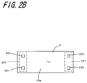
- FIG. 2B is a bottom view showing the appearance of the liquid sample sensor 2 ;
- FIG. 3 is a sectional view of the liquid sample sensor 2 taken along the line A-A in FIG. 2A ;
- FIG. 4 is a plan view of the sensor element 21 ;
- FIG. 5 is a schematic block diagram showing the sensor device 1 in a first arrangement
- FIG. 6 is a schematic block diagram showing the sensor device 1 in a second arrangement
- FIG. 7 is a plan view of the sensor element 21 A
- FIG. 8A is a plan view showing the appearance of a modified example of the liquid sample sensor 2 ;
- FIG. 8B is a bottom view showing the appearance of a modified example of the liquid sample sensor 2 ;
- FIG. 9A is a plan view showing the appearance of a modified example of a reader 3 ;
- FIG. 9B is a bottom view showing the appearance of a modified example of the reader 3 ;
- FIG. 10 is an external view showing another modified example of the liquid sample sensor 2 ;
- FIG. 11A is a plan view showing the appearance of a liquid sample sensor 5 ;
- FIG. 11B is a bottom view showing the appearance of the liquid sample sensor 5 ;
- FIG. 12 is a schematic block diagram showing a sensor device 4 in accordance with a second embodiment of the invention in the first arrangement
- FIG. 13 is a schematic block diagram showing the sensor device 4 in the second arrangement
- FIG. 14A is a plan view showing the appearance of a modified example of the liquid sample sensor 5 ;
- FIG. 14B is a bottom view showing the appearance of a modified example of the liquid sample sensor 5 ;
- FIG. 15A is a plan view showing the appearance of the liquid sample sensor 5 ;
- FIG. 15B is a bottom view showing the appearance of the liquid sample sensor 5 ;
- FIG. 16 is a schematic drawing showing a modified example of a reader 6 ;
- FIG. 17 is a schematic drawing showing the structure of a sensor device 8 in accordance with a third embodiment of the invention.
- FIG. 18A is a plan view showing the appearance of a liquid sample sensor 9 ;
- FIG. 18B is a bottom view showing the appearance of the liquid sample sensor 9 ;
- FIG. 19 is a schematic block diagram showing the sensor device 8 in accordance with the third embodiment of the invention.
- FIG. 20 is a schematic block diagram showing a sensor device 8 A of a modified example of the third embodiment of the invention.
- FIG. 21 is a schematic block diagram showing a sensor device 8 B of a modified example of the third embodiment of the invention.
- FIG. 22 is a schematic block diagram showing a sensor device 8 C of a modified example of the third embodiment of the invention.
- FIG. 23A is a schematic block diagram (first arrangement) showing a sensor device 1 A in accordance with a fourth embodiment of the invention.
- FIG. 23B is a schematic block diagram (second arrangement) showing the sensor device 1 A in accordance with the fourth embodiment of the invention.
- FIG. 24 is a flow chart showing procedures in a detecting method in accordance with a fifth embodiment of the invention.
- FIG. 25 is a schematic block diagram showing a liquid sample sensor 2 D of a modified example of the first embodiment of the invention.
- a sensor is exemplified by a liquid sample sensor which carries out sensing operation using a sample in liquid form, and, a measurement portion is exemplified by a reader built as a device including various constituent elements.
- FIG. 1 is a schematic drawing showing the structure of a sensor device 1 in accordance with a first embodiment of the invention.
- FIGS. 2A and 2B are external views showing the configuration of a liquid sample sensor 2 .
- FIG. 2A is a plan view
- FIG. 2B is a bottom view.
- the sensor device 1 includes the liquid sample sensor 2 serving as a sensor and a reader 3 serving as a measurement portion in which the liquid sample sensor 2 is detachably mounted.
- the liquid sample sensor 2 at least absorbs or receives a liquid sample, causes an electric signal supplied from the reader 3 to vary according to the properties or constituent components of the liquid sample, and, and outputs the varied electric signal to the reader 3 .
- the reader 3 supplies an electric signal to the liquid sample sensor 2 , and also receives an electric signal outputted from the liquid sample sensor 2 .
- the liquid sample sensor 2 is made as a disposable cartridge.
- the used liquid sample sensor 2 is replaced with a new liquid sample sensor 2 which is to be set in the reader 3 for the succeeding liquid sample sensing operation.
- the liquid sample sensor 2 includes a sensor main body 20 including a first face 20 a , a sensor element 21 located in the sensor main body 20 , and a plurality of external terminals 22 located on the first face 20 a of the sensor main body 20 .
- the external terminals 22 are electrically connected to the sensor element 21 .
- the reader 3 includes a reader main body 30 including a second face 30 a opposed to the first face 20 a of the liquid sample sensor 2 , a plurality of connection terminals 31 positioned so as to correspond one-to-one to the plurality of external terminals 22 , and a control section 32 which is electrically connected to the plurality of connection terminals 31 , and which carries out inputting and outputting electric signals.
- the sensor main body 20 is shaped in a plate.
- One of the flat surfaces of the sensor main body 20 which are perpendicular to the thickness direction is defined as the first face 20 a
- the other flat surface is defined as a third face 20 b .
- the first face 20 a is provided with the external terminals 22
- the third face 20 b is provided with an inlet 20 c for introduction of a liquid sample and an outlet 20 d for discharge of a liquid sample.
- a liquid sample is subjected to detection process in the sensor element 21 located in the sensor main body 20 , and, following the completion of detection, the liquid sample is discharged from the outlet 20 d .
- FIG. 3 is a sectional view of the liquid sample sensor 2 taken along the line A-A in FIG. 2A .
- the sensor element 21 has a metallic film 7 a with a reactant immobilized thereon for reaction with an object to be detected.
- the selection of the reactant may be predicated upon the type of an object to be detected, viz., a detection object.
- a detection object is a specific cell or living tissue in a liquid sample
- an antibody, and an aptamer made of nucleic acid and peptide may be used as the reactant.
- the reactant and the detection object may be bound to each other under chemical reaction or antigen-antibody reaction.
- the form of reaction is not so limited, and thus, the detection object may be bound to or adsorbed on the reactant under interaction between the detection object and the reactant.
- a characteristic of a signal transmitted from a signal-transmitting electrode such as an IDT (InterDigital Transducer) electrode varies according to the type or content of the detection object.
- the signal having the varied characteristic is received as a detection signal by a signal-receiving electrode such as an IDT electrode.
- a mass corresponding to an increase of the detection object contained in the sample can be detected.
- the signal characteristic employed may be any given characteristic which varies with a change in the mass of the metallic film 7 a without specific limitation. For example, where the signal is of elastic wave signals, the phase of the signal may be employed as the signal characteristic to be varied.
- a flow channel 80 extending from the inlet 20 c to the outlet 20 d to bring the liquid sample introduced in the sensor main body 20 from the inlet 20 c into contact with the metallic film 7 a and the metallic film 7 b.
- FIG. 4 is a plan view of the sensor element 21 .
- the sensor element 21 includes a detection section and a reference section.
- the detection section includes a first IDT electrode 11 which generates an elastic wave which propagates toward the metallic film 7 a and a second IDT electrode 12 which receives the elastic wave which has passed through the metallic film 7 a
- the reference section includes a first IDT electrode 13 which generates an elastic wave which propagates toward the metallic film 7 b and a second IDT electrode 14 which receives the elastic wave which has passed through the metallic film 7 b .
- the first IDT electrode 11 and the first IDT electrode 13 are each connected to a pair of first draw-out electrodes 15
- the second IDT electrode 12 and the second IDT electrode 14 are each connected to a pair of second draw-out electrodes 16 .
- One of the pair of first draw-out electrodes 15 and one of the pair of second draw-out electrodes 16 are each connected to the plurality of connection terminals 31 of the reader 3 .
- the other one of the pair of first draw-out electrodes 15 and the other one of the pair of second draw-out electrodes 16 are disposed so that they can be connected to the ground (earth) electrode of the reader 3 even if any one of a first arrangement and a second arrangement is taken up as will hereafter be described.
- the first face 20 a of the liquid sample sensor 2 is provided with a plurality of external terminals 22 which are electrically connected to a plurality of connection terminals 31 located in the reader 3 .
- the plurality of external terminals 22 are located on the first face 20 a so as to exhibit rotational symmetry. While the present embodiment will be described with respect to the case where the liquid sample sensor 2 includes four external terminals as the plurality of external terminals 22 , the number of the external terminals 22 is not limited to a specific value, and may thus be determined in conformity with input and output numbers for the sensor element 21 , for example.
- the first face 20 a and the third face 20 b have the same quadrangular (rectangular) shape.
- Each external terminal 22 has a square shape.
- the external terminals 22 do not necessarily have to have the same shape, and may thus be made to have different shapes.
- the pattern of placement of these four external terminals 22 a , 22 b , 22 c , and 22 d exhibits two-fold rotational symmetry.
- the pattern of placement of the four external terminals 22 a , 22 b , 22 c , and 22 d exhibits two-fold rotational symmetry, and thus, even after a 180° rotation of the liquid sample sensor about the rotation center c 1 , the pattern of terminal placement remains the same.
- the second face 30 a opposed to the first face 20 a has a rectangular shape.
- the second face 30 a defines the bottom of a recess formed in the surface of the reader main body 30 .
- An inner periphery 30 b of the recess extends along the outer periphery of the second face 30 a serving as the recess bottom, and also extends substantially vertically from the second face 30 a .
- the opening of the recess has a rectangular shape.
- the second face 30 a is provided with a plurality of connection terminals 31 each disposed so as to make electrical connection with corresponding one of the external terminals 22 of the liquid sample sensor 2 .
- the connection terminals 31 correspond in number with the external terminals, that is; there are provided four connection terminals 31 which are connected to the four external terminals 22 a , 22 b , 22 c , and 22 d , respectively.
- the four connection terminals are arranged so as to exhibit two-fold rotational symmetry.
- the liquid sample sensor 2 is set in the reader 3 .
- the setting of the liquid sample sensor 2 in the reader 3 may be taken to mean the establishment of electrical connection between the external terminal 22 of the liquid sample sensor 2 and the connection terminal of the reader 3 .
- the liquid sample sensor 2 may be mounted so as to lie on the surface of the reader 3 .
- the external terminals 22 are arranged so as to exhibit two-fold rotational symmetry.
- the electrical connection between the external terminal 22 of the liquid sample sensor 2 and the connection terminal of the reader 3 can be established not only when the liquid sample sensor 2 is set in an oriented position to permit electrical connection between the external terminal 22 of the liquid sample sensor 2 and the connection terminal of the reader 3 (first arrangement), but also when the liquid sample sensor 2 is set in another oriented position to which it has been shifted after a rotation of 180° about the rotation center c 1 (second arrangement).
- the liquid sample sensor 3 can be set in any one of two oriented positions corresponding to the first arrangement and the second arrangement, respectively, that is; measurement can be carried out both in the first arrangement and in the second arrangement. This makes it possible to reduce time and effort imposed on the work in preparation for measurement such as the trouble of having to set the liquid sample sensor 2 in a correct oriented position, and thereby enable the user to carry out measurement by simple operation without any regard to the orientation of the liquid sample sensor 2 .
- the liquid sample sensor 2 at the time of mounting the liquid sample sensor 2 having a rectangular plate-like outside shape so that the first face 20 a can be located on the second face 30 a of the reader 3 , the liquid sample sensor 2 is guidedly introduced into the opening having a rectangular outside shape, whereupon the first face 20 a and the second face 30 a are disposed so as to face each other as viewed in the plan view.
- each of the four external terminals 22 a , 22 b , 22 c , and 22 d of the first face 20 a abuts against corresponding one of the four connection terminals of the second face 30 a , thus assuring electrical connection between the external terminal and the connection terminal.
- the recess formed in the main body of the reader 3 as a guide to guide the liquid sample sensor 2 , the user can carry out measurement with greater ease in operation without any regard not only to the orientation of the liquid sample sensor 2 but also to the location of the terminal.
- FIG. 5 is a schematic block diagram showing the sensor device 1 in the first arrangement
- FIG. 6 is a schematic block diagram showing the sensor device 1 in the second arrangement.
- the external terminal and the connection terminal are connected as follows.
- the first external terminal 22 a of the liquid sample sensor 2 is electrically connected to the first connection terminal 31 a of the reader 3 .
- the second external terminal 22 b of the liquid sample sensor 2 is electrically connected to the second connection terminal 31 b of the reader 3 .
- the third external terminal 22 c of the liquid sample sensor 2 is electrically connected to the third connection terminal 31 c of the reader 3 .
- the fourth external terminal 22 d of the liquid sample sensor 2 is electrically connected to the fourth connection terminal 31 d of the reader 3 .
- the first external terminal 22 a and the second external terminal 22 b of the liquid sample sensor 2 are electrically connected to a detection section 21 a which produces a detection signal for detection of a detection object contained in a sample in the sensor element 21 .
- the third external terminal 22 c and the fourth external terminal 22 d of the liquid sample sensor 2 are electrically connected to a reference section 21 b which produces a reference signal which serves as a reference for the detection signal in the sensor element 21 .
- Each of the first external terminal 22 a , the second external terminal 22 b , the third external terminal 22 c , and the fourth external terminal 22 d serves as both of an input terminal which receives an electric signal input and an output terminal which produces an electric signal output.
- each of the first external terminal 22 a and the third external terminal 22 c receives an electric signal input from the reader 3 , and, in the second arrangement, each of them constitutes a first external terminal group 220 which gives an electric signal output to the reader 3 .
- each of the second external terminal 22 b and the fourth external terminal 22 d gives an electric signal output to the reader 3 , and, in the second arrangement, each of them constitutes a second external terminal group 221 which receives an electric signal input from the reader 3 .
- the control section 32 inputs an electric signal to the first connection terminal 31 a and the third connection terminal 31 c , which constitute a first connection terminal group 310 , and supplies the electric signal to the liquid sample sensor 2 . Moreover, the control section 32 receives an electric signal (including a detection signal and a reference signal) outputted from the liquid sample sensor 2 by the second connection terminal 31 b and the fourth connection terminal 31 d which constitute a second connection terminal group 311 .
- the electrical connection between the first connection terminal 31 a of the reader 3 and the first external terminal 22 a of the liquid sample sensor 2 permits the supply of electric signals from the reader 3 to the detection section 21 a of the liquid sample sensor 2 .
- the electrical connection between the second connection terminal 31 b of the reader 3 and the second external terminal 22 b of the liquid sample sensor 2 enables the reader 3 to receive a detection signal produced in the detection section 21 a .
- the electrical connection between the third connection terminal 31 c of the reader 3 and the third external terminal 22 c of the liquid sample sensor 2 permits the supply of electric signals from the reader 3 to the reference section 21 b of the liquid sample sensor 2 .
- the electrical connection between the fourth connection terminal 31 d of the reader 3 and the fourth external terminal 22 d of the liquid sample sensor 2 enables the reader 3 to receive a reference signal produced in the reference section 21 b .
- the reader 3 produces the result of detection of a detection object based on the detection signal and the reference signal received.
- the external terminal and the connection terminal are connected as follows.
- the first external terminal 22 a of the liquid sample sensor 2 is electrically connected to the fourth connection terminal 31 d of the reader 3 .
- the second external terminal 22 b of the liquid sample sensor 2 is electrically connected to the third connection terminal 31 c of the reader 3 .
- the third external terminal 22 c of the liquid sample sensor 2 is electrically connected to the second connection terminal 31 b of the reader 3 .
- the fourth external terminal 22 d of the liquid sample sensor 2 is electrically connected to the first connection terminal 31 a of the reader 3 .
- the electrical connection between the first connection terminal 31 a of the reader 3 and the fourth external terminal 22 d of the liquid sample sensor 2 permits the supply of electric signals from the reader 3 to the reference section 21 b of the liquid sample sensor 2 .
- the electrical connection between the second connection terminal 31 b of the reader 3 and the third external terminal 22 c of the liquid sample sensor 2 enables the reader 3 to receive a reference signal produced in the reference section 21 b .
- the electrical connection between the third connection terminal 31 c of the reader 3 and the second external terminal 22 b of the liquid sample sensor 2 permits the supply of electric signals from the reader 3 to the detection section 21 a of the liquid sample sensor 2 .
- the electrical connection between the fourth connection terminal 31 d of the reader 3 and the first external terminal 22 a of the liquid sample sensor 2 enables the reader 3 to receive a detection signal produced in the detection section 21 a .
- the control section 32 produces the result of detection of a detection object based on the detection signal and the reference signal received.
- the detection signal is received by the fourth connection terminal 31 d and the reference signal is received by the second connection terminal 31 b .
- the control section 32 determines whether the signal received by the second connection terminal 31 b is a detection signal or a reference signal, and also determines whether the signal received by the fourth connection terminal 31 d is a detection signal or a reference signal, prior to the production of a detection result. For example, in the present embodiment, the control section 32 determines which one of the signal received by the second connection terminal 31 b and the signal received by the fourth connection terminal 31 d is a reference signal. When one of the received signals is identified as a reference signal, the other can be judged as a detection signal accordingly.
- a reference signal exhibits a certain variation tendency (profile) over time regardless of whether a detection object is contained in a sample or not.
- the certain variation tendency include the tendency for a signal value to remain unchanged for a predetermined period of time since the onset of signal reception and the tendency for a signal value to increase monotonically for a predetermined period of time since the onset of signal reception.
- it is advisable to record a certain variation tendency of a signal identified as a reference signal viz., a signal which was found to occur in the reference section 21 b , obtained in advance on the basis of signal value variations, etc.
- a comparison is carried out between the recorded data of a certain variation tendency and the data of variation tendencies exhibited by signals received by the second connection terminal 31 b over a certain time duration, as well as the data of the variation tendencies exhibited by signals received by the fourth connection terminal 31 d over a certain time duration.
- a signal which is found to exhibit the variation tendency coinciding with the recorded certain variation tendency is judged as a reference signal.
- whether the received signal is a reference signal or not may alternatively be determined by the control section 32 as follows.
- a certain amount of time is required to obtain the variation tendency of a received signal, and in addition, the possibility may arise that accurate identification cannot be carried out when the variation tendency of a received signal does not coincide with the recorded certain variation tendency.
- the layout of IDT electrodes in the reference section may be changed in the interest of accurate identification of a reference signal.
- the sensor element 21 A shown in FIG. 4 in the sensor element 21 A shown in FIG.
- the distance between the first IDT electrode 11 which generates an elastic wave which propagates toward the metallic film 7 a and the second IDT electrode 12 which receives the elastic wave which has passed through the metallic film 7 a in the detection section is equal to the distance between the first IDT electrode 13 and the second IDT electrode 14 in the reference section.
- the metallic film 7 a and the metallic film 7 b have the same surface condition (for example, the surface of each metallic film is free of immobilization of a reactant which reacts with a detection object), when electric signals are delivered to the detection section and the reference section prior to the supply of a liquid sample to the sensor element 21 , the signal received by the second connection terminal 31 b and the signal received by the fourth connection terminal 31 d are in phase.
- the distance between the first IDT electrode 13 A and the second IDT electrode 14 A in the reference section is greater than the distance between the first IDT electrode 11 and the second IDT electrode 12 in the detection section.
- the surface condition difference-caused phase difference may be employed for signal detection.
- liquid sample sensor 2 has been illustrated as being configured so that, of the four external terminals provided therein, one set of two external terminals constitutes the first external terminal group, and the other set of two external terminals constitutes the second external terminal group, and that the first external terminal group and the second external terminal group are opposed to each other with respect to the rotation center c 1 lying in between, this design is not intended to be limiting of the present embodiment.
- the number of the external terminals may be six or eight, or more.
- FIGS. 8A and 8B are each an external view showing a modified example of the liquid sample sensor 2 .
- FIGS. 8A and 8B for a better understanding of the layout of external terminals, there is shown only the appearance of the first face 20 a of each of liquid sample sensors 2 A and 2 B implemented as modified examples.
- the third face 20 b of each of the liquid sample sensors 2 A and 2 B may be either identical with or different from the third face 20 b of the liquid sample sensor 2 shown in FIG. 2A .
- 8A there are provided eight external terminals 22 , that is, in addition to the above-described four external terminals 22 a , 22 b , 22 c , and 22 d , there are provided four external terminals 22 e , 22 f , 22 g , and 22 h . These eight external terminals 22 are arranged so as to exhibit two-fold rotational symmetry.
- the external terminals 22 e and 22 g belong, together with the external terminals 22 a and 22 c , to the first external terminal group 220
- the external terminals 22 f and 22 h belong, together with the external terminals 22 b and 22 d , to the second external terminal group 221 .
- the four external terminals 22 e , 22 f , 22 g , and 22 h are each electrically connected to corresponding one of two additional detection sections or corresponding one of two additional reference sections, or corresponding one of a single additional detection section and a single additional reference section.
- the total number of the detection and reference sections is four.
- the external terminals are line-symmetrically arranged with respect to an axis of symmetry passing through the rotation center c 1 .
- the external terminal 22 i belongs, together with the external terminals 22 a and 22 c , to the first external terminal group 220
- the external terminal 22 j belongs, together with the external terminals 22 b and 22 d , to the second external terminal group 221 .
- the two external terminals 22 i and 22 j are each electrically connected to an additional detection section or an additional reference section.
- the total number of the detection and reference sections is three.
- the external terminals 22 are arranged so as to exhibit rotational symmetry, and so the user can carry out measurement both in the first arrangement and in the second arrangement regardless of the number of terminals. This enables the user to carry out measurement by simple operation with less effort.
- FIG. 9A is a schematic drawing showing a reader 3 A which is a modified example of the reader.
- the plurality of connection terminals 31 for example, eight connection terminals are provided on the second face 30 a of the reader 3 A.
- eight connection terminals 31 four connection terminals 31 a , 31 c , 31 e , and 31 g are disposed along one of the short sides of the rectangular second face 30 a , and the rest, namely four connection terminals 31 b , 31 d , 31 f , and 31 h are disposed along the other one of the short sides.
- These eight connection terminals 31 are arranged so as to exhibit two-fold rotational symmetry.
- connection terminals 31 a , 31 c , 31 e , and 31 g disposed along one short side are each intended to feed electric signals to the liquid sample sensor 2
- the four connection terminals 31 b , 31 d , 31 f , and 31 h disposed along the other short side are each intended to receive electric signals (including a detection signal and a reference signal) outputted from the liquid sample sensor 2 .
- electric signal-output connection terminals are located on one side of the reader, whereas electric signal-input connection terminals are located on the other side of the reader. This positioning leaves a sufficient spacing between the electric signal-output connection terminal and the electric signal-input connection terminal, with consequent reduction in electromagnetic interference between an outputted electric signal and an inputted electric signal.
- FIG. 9B is a schematic drawing showing a modified example of the reader 3 .
- the connection terminals 31 for example, eight connection terminals are provided on the second face 30 a of the reader 3 A.
- the eight connection terminals 31 four connection terminals 31 a , 31 c , 31 e , and 31 g are disposed along one of the short sides of the rectangular second face 30 a , and the rest, namely four connection terminals 31 b , 31 d , 31 f , and 31 h are disposed along the other one of the short sides.
- These eight connection terminals 31 are arranged so as to exhibit two-fold rotational symmetry.
- connection terminals 31 a , 31 c , 31 e , and 31 g disposed along one short side are classified as terminals for feeding electric signals to the liquid sample sensor 2 and terminals for receiving electric signals (including a detection signal and a reference signal) outputted from the liquid sample sensor 2 .
- connection terminals 31 b , 31 d , 31 f , and 31 h disposed along the other short side are classified as terminals for feeding electric signals to the liquid sample sensor 2 and terminals for receiving electric signals (including a detection signal and a reference signal) outputted from the liquid sample sensor 2 .
- connection terminals 31 a , 31 c , 31 e , and 31 g disposed along one short side the connection terminals 31 a and 31 c located closer to the corresponding ends of one short side serve to feed electric signals to the liquid sample sensor 2 , and the centrally located two connection terminals 31 e and 31 g serve to receive electric signals (including a detection signal and a reference signal) outputted from the liquid sample sensor 2 .
- connection terminals 31 b , 31 d , 31 f , and 31 h disposed along the other short side serve to feed electric signals to the liquid sample sensor 2
- connection terminals 31 b and 31 d located closer to the corresponding ends of the other short side serve to receive electric signals outputted from the liquid sample sensor 2 .
- the present modified example can be implemented under conditions where no specific limitation is imposed upon the layout of the output-receiving terminals and the signal-feeding terminals.
- the output-receiving terminal and the signal-feeding terminal can be disposed adjacent each other.
- internal wiring for connection between the control section 32 and each connection terminal can be configured with greater design flexibility.
- the shape of the first face 20 a is not limited as long as the pattern of placement of the external terminals 22 exhibits two-fold rotational symmetry. That is, there is no need for the first face 20 a to be shaped so as to bear a certain relation to the two-fold rotational symmetry of the pattern of placement of the external terminal 22 .
- the two-fold rotational symmetry of the first face 20 a does not necessarily have to be the same as the two-fold rotational symmetry of the pattern of placement of the external terminal 22 .
- FIG. 10 is an external view showing another modified example of the liquid sample sensor 2 .
- the pattern of placement of four external terminals 22 exhibits two-fold rotational symmetry. More specifically, the first external terminal 22 a and the fourth external terminal 22 d lie in one of diagonal lines drawn on the square-shaped first face 20 a , whereas the second external terminal 22 b and the third external terminal 22 c lie in the other diagonal line drawn on the square-shaped first face 20 a .
- the distance between the first external terminal 22 a and the fourth external terminal 22 d is greater than the distance between the second external terminal 22 b and the third external terminal 22 c .
- the first external terminal 22 a and the second external terminal 22 b are electrically connected to the detection section 21 a
- the third external terminal 22 c and the fourth external terminal 22 d are electrically connected to the reference section 21 b .
- the electrical connection between the external terminal 22 of the liquid sample sensor 2 and the connection terminal of the reader 3 can be established in any one of two different arrangements, namely the first arrangement and the second arrangement that differ 180° from each other in the orientation of the liquid sample sensor 2 . This enables the user to carry out measurement by simple operation with less effort.
- FIGS. 11A and 11B are each an external view showing the configuration of a liquid sample sensor 5 .
- FIG. 11A is a plan view
- FIG. 11B is a bottom view.
- FIG. 12 is a schematic block diagram showing a sensor device 4 in accordance with a second embodiment of the invention in the first arrangement
- FIG. 13 is a schematic block diagram showing the sensor device 4 in the second arrangement.
- the sensor device 4 includes the liquid sample sensor 5 and a reader 6 in which the liquid sample sensor 5 is detachably mounted.
- the liquid sample sensor 5 and the reader 6 are similar in function to the liquid sample sensor 2 and the reader 3 , respectively, of the first embodiment.
- the liquid sample sensor 5 at least absorbs or receives a liquid sample, causes an electric signal supplied from the reader 6 to vary according to the properties or constituent components of the liquid sample, and outputs the varied electric signal to the reader 6 .
- the reader 6 supplies an electric signal to the liquid sample sensor 5 , and also receives an electric signal outputted from the liquid sample sensor 5 .
- the liquid sample sensor 5 includes a sensor main body 50 having a first face 50 a , a sensor element 51 located in the sensor main body 50 , and a plurality of external terminals 52 located on the first face 50 a of the sensor main body 50 .
- the external terminals 52 are electrically connected to the sensor element 51 .
- the reader 6 includes a reader main body 60 having a second face 60 a opposed to the first face 50 a of the liquid sample sensor 5 , a plurality of connection terminals 61 positioned so as to correspond one-to-one to the plurality of external terminals 52 , and a control section 62 which is electrically connected to the plurality of connection terminals 61 , and which carries out inputting and outputting electric signals.
- the sensor main body 50 is shaped in a plate.
- One of the flat surfaces of the sensor main body 50 which are perpendicular to the thickness direction is defined as the first face 50 a
- the other flat surface is defined as a third face 50 b .
- the first face 50 a is provided with the external terminals 52
- the third face 50 b is provided with an inlet 50 c for introduction of a liquid sample and an outlet 50 d for discharge of a liquid sample.
- a liquid sample After being supplied to the sensor main body 50 through the inlet 50 c , a liquid sample is subjected to detection process in the sensor element 51 located in the sensor main body 50 , and, following the completion of detection, the liquid sample is discharged from the outlet 50 d.
- the plurality of external terminals 52 are disposed on the first face 50 a so as to exhibit rotational symmetry. While the present embodiment will be described with respect to the case where the liquid sample sensor 5 includes four external terminals as the plurality of external terminals, the number of the external terminals 52 is not limited to a specific value, and may thus be determined in conformity with input and output numbers for the sensor element 51 , for example.
- the first face 50 a and the third face 50 b have the same square shape.
- Each external terminal 52 has a square shape.
- the external terminals 52 do not necessarily have to have the same shape, and may thus be made to have different shapes.
- These four external terminals 52 a , 52 b , 52 c , and 52 d are arranged so as to exhibit four-fold rotational symmetry.
- the centroid of a square whose four vertices coincide with the centers of the four external terminals 52 a , 52 b , 52 c , and 52 d , respectively, defines the rotation center c 2 of rotational symmetry.
- the third external terminal 52 a and the sixth external terminal 52 d are opposed to each other with respect to the rotation center c 2 lying in between.
- the fourth external terminal 52 b and the fifth external terminal 52 c are opposed to each other with respect to the rotation center c 2 lying in between.
- the pattern of placement of the four external terminals 52 a , 52 b , 52 c , and 52 d exhibits four-fold rotational symmetry, and thus, even after each and every 90° rotation of the liquid sample sensor about the rotation center c 2 , the pattern of terminal placement remains the same.
- an arrangement as shown in FIG. 12 is defined as the first arrangement serving as a reference arrangement
- an arrangement as shown in FIG. 13 attained by a 90° rotation of the liquid sample sensor from the original position is defined as the second arrangement.
- an arrangement attained by a 180° rotation of the liquid sample sensor is defined as the third arrangement
- an arrangement attained by a 270° rotation of the liquid sample sensor is defined as the fourth arrangement.
- the four connection terminals 61 of the reader 6 are also arranged so as to four-fold rotational symmetry.
- each external terminal 52 of the liquid sample sensor 5 makes electrical connection with a different connection terminal 61 of the reader 6 with a change from the first arrangement to the second arrangement and vice versa.
- the external terminal and the connection terminal are connected as follows.
- the third external terminal 52 a of the liquid sample sensor 5 is electrically connected to the third connection terminal 61 a of the reader 6 .
- the fourth external terminal 52 b of the liquid sample sensor 5 is electrically connected to the fourth connection terminal 61 b of the reader 6 .
- the fifth external terminal 52 c of the liquid sample sensor 5 is electrically connected to the fifth connection terminal 61 c of the reader 6 .
- the sixth external terminal 52 d of the liquid sample sensor 5 is electrically connected to the sixth connection terminal 61 d of the reader 6 .
- the third external terminal 52 a and the fourth external terminal 52 b of the liquid sample sensor 5 are electrically connected to a detection section 51 a in the sensor element 51 .
- the fifth external terminal 52 c and the sixth external terminal 52 d of the liquid sample sensor 5 are electrically connected to a reference section 51 b in the sensor element 51 .
- Each of the third external terminal 52 a , the fourth external terminal 52 b , the fifth external terminal 52 c , and the sixth external terminal 52 d serves as both of an input terminal which receives an electric signal input and an output terminal which produces an electric signal output.
- the control section 62 inputs an electric signal to the third connection terminal 61 a and the sixth connection terminal 61 d , and supplies the electric signal to the liquid sample sensor 5 . Moreover, the control section 62 receives an electric signal (including a detection signal and a reference signal) outputted from the liquid sample sensor 5 by the fourth connection terminal 61 b and the fifth connection terminal 61 c.
- the electrical connection between the third connection terminal 61 a of the reader 6 and the third external terminal 52 a of the liquid sample sensor 5 permits the supply of electric signals from the reader 6 to the detection section 51 a of the liquid sample sensor 5 .
- the electrical connection between the fourth connection terminal 61 b of the reader 6 and the fourth external terminal 52 b of the liquid sample sensor 5 enables the reader 6 to receive a detection signal produced in the detection section 51 a .
- the electrical connection between the sixth connection terminal 61 d of the reader 6 and the sixth external terminal 52 d of the liquid sample sensor 5 permits the supply of electric signals from the reader 6 to the reference section 51 b of the liquid sample sensor 5 .
- the electrical connection between the fifth connection terminal 61 c of the reader 6 and the fifth external terminal 52 c of the liquid sample sensor 5 enables the reader 6 to receive a reference signal produced in the reference section 51 b .
- the reader 6 produces the result of detection of a detection object based on the detection signal and the reference signal received.
- the external terminal and the connection terminal are connected as follows.
- the third external terminal 52 a of the liquid sample sensor 5 is electrically connected to the fourth connection terminal 61 b of the reader 6 .
- the fourth external terminal 52 b of the liquid sample sensor 5 is electrically connected to the sixth connection terminal 61 d of the reader 6 .
- the fifth external terminal 52 c of the liquid sample sensor 5 is electrically connected to the third connection terminal 61 a of the reader 6 .
- the sixth external terminal 52 d of the liquid sample sensor 5 is electrically connected to the fifth connection terminal 61 c of the reader 6 .
- the electrical connection between the third connection terminal 61 a of the reader 6 and the fifth external terminal 52 c of the liquid sample sensor 5 permits the supply of electric signals from the reader 6 to the reference section 51 b of the liquid sample sensor 5 .
- the electrical connection between the sixth connection terminal 61 d of the reader 6 and the fourth external terminal 52 b of the liquid sample sensor 5 permits the supply of electric signals to the detection section 51 a .
- the electrical connection between the fifth connection terminal 61 c of the reader 6 and the sixth external terminal 52 d of the liquid sample sensor 5 enables the reader 6 to receive a reference signal produced in the reference section 51 b of the liquid sample sensor 5 .
- the electrical connection between the fourth connection terminal 61 b of the reader 6 and the third external terminal 52 a of the liquid sample sensor 5 enables the reader 6 to receive a detection signal produced in the detection section 51 a .
- the control section 62 produces the result of detection of a detection object based on the detection signal and the reference signal received.
- a detection signal is received by the fourth connection terminal 61 b
- a reference signal is received by the fifth connection terminal 61 c .
- the control section 62 determines whether the signal received by the fourth connection terminal 61 b is a detection signal or a reference signal, and also determines whether the signal received by the fifth connection terminal 61 c is a detection signal or a reference signal, prior to the production of a detection result. For example, in the present embodiment, the control section 62 determines which one of the signal received by the fourth connection terminal 61 b and the signal received by the fifth connection terminal 61 c is a reference signal.
- the other can be judged as a detection signal accordingly.
- the judgment as to whether the received signal is a reference signal or not is made in the same manner as that adopted in the first embodiment, and thus the description thereof will be omitted.
- the result of detection of a detection object can be outputted from the control section 62 also in the case with the third arrangement attained by a 180° rotation of the liquid sample sensor from the position corresponding to the first arrangement, as well as in the case with the fourth arrangement attained by a 270° rotation thereof from the position corresponding to the first arrangement.
- the liquid sample sensor 5 in setting the liquid sample sensor 5 in the reader 6 to carry out measurement, according to the second embodiment, can be set in any one of four oriented positions (corresponding to the first to fourth arrangements, respectively). In any one of the four arrangements, detection results can be outputted from the control section 62 . This enables the user to carry out measurement by simple operation with less effort.
- FIGS. 14A and 14B are each an external view showing a modified example of the liquid sample sensor 5 .
- FIGS. 14A and 14B for a better understanding of the layout of external terminals, there is shown only the appearance of the first face 50 a of each of liquid sample sensors 5 A and 5 B implemented as modified examples.
- the third face 50 b of each of the liquid sample sensors 5 A and 5 B may be either identical with or different from the third face of the liquid sample sensor 5 shown in FIG. 11 .
- the liquid sample sensor 5 B shown in FIG. 14B there are provided four external terminals 52 a , 52 b , 52 c , and 52 d , each located closer to one of two vertices defining the opposite ends of a corresponding side of the first face 50 a with respect to the center of the side, which are equidistant from the corresponding sides of the first face 50 a .
- the third external terminal 52 a and the sixth external terminal 52 d are opposed to each other with respect to the rotation center c 2 lying in between, and the fourth external terminal 52 b and the fifth external terminal 52 c are opposed to each other with respect to the rotation center c 2 lying in between.
- the external terminals 52 are arranged so as to exhibit four-fold rotational symmetry, and so the user can carry out measurement regardless of the shape of the first face 50 a and the terminal positioning within the first face 50 a , even if-any one of the first to fourth arrangements is taken up. This enables the user to carry out measurement by simple operation with less effort.
- FIG. 15 is an external view showing a modified example of the liquid sample sensor 5 .
- FIG. 15A is a plan view
- FIG. 15B is a bottom view.
- FIG. 16 is a schematic drawing showing a modified example of the reader 6 .
- a liquid sample sensor 5 C implemented as a modification example, eight connection terminals 52 are disposed on the first face 50 a .
- the eight connection terminals 52 which are arranged along the four sides of the first face 50 a , include four external terminals 52 a , 52 b , 52 c , and 52 d each located at corresponding one of the four corners of the first face 50 a , and four external terminals 52 e , 52 f , 52 g , and 52 h , each lying in the bisector of a corresponding side of the first face 50 a , which are equidistant from the corresponding sides of the first face 50 a .
- Such a pattern of placement of the eight external terminals 52 exhibits four-fold rotational symmetry.
- a reader 6 A implemented as a modified example includes, on a second face 60 a thereof, eight connection terminals 61 positioned so as to correspond one-to-one to the eight external terminals 52 of the liquid sample sensor 5 C. That is, there are provided four connection terminals 61 a , 61 b , 61 c , and 61 d each situated at corresponding one of the four corners of the second face 60 a , and four connection terminals 61 e , 61 f , 61 g , and 61 h , each lying in the bisector of a corresponding side of the second face 60 a , which are equidistant from the corresponding sides of the second face 60 a .
- connection terminals 61 a , 61 b , 61 c , and 61 d each located at corresponding one of the four corners, the connection terminals 61 a and 61 d lie in one of diagonal lines drawn on the second face 60 a , whereas the connection terminals 61 b and 61 c lie in the other diagonal line.
- connection terminals 61 a and 61 d lying in one diagonal line serve to feed electric signals to the liquid sample sensor 2
- the connection terminals 61 b and 61 c lying in the other diagonal line serve to receive electric signals (including a detection signal and a reference signal) outputted from the liquid sample sensor 2
- the connection terminals 61 e and 61 h opposed to each other with respect to the rotation center c 2 lying in between serve to feed electric signals to the liquid sample sensor 2
- the other two connection terminals 61 f and 61 g opposed to each other with respect to the rotation center c 2 lying in between serve to receive electric signals outputted from the liquid sample sensor 2 .
- connection terminals 61 are classified as four feeding terminals and four receiving terminals, then the feeding terminals and the receiving terminals are arranged so as to exhibit rotational symmetry with respect to the rotation center c 2 .
- the external terminals 52 are arranged so as to exhibit four-fold rotational symmetry, and so the user can carry out measurement regardless of the number of terminals even if any one of the first to fourth arrangements is taken up. This enables the user to carry out measurement by simple operation with less effort.
- FIG. 17 is a schematic drawing showing the structure of a sensor device 8 in accordance with a third embodiment of the invention.
- FIGS. 18A and 18B are external views showing the configuration of a liquid sample sensor 9 .
- FIG. 18A is a plan view
- FIG. 18B is a bottom view.
- the sensor device 8 includes the liquid sample sensor 9 and a reader 10 in which the liquid sample sensor 9 is detachably mounted.
- the liquid sample sensor 9 and the reader 10 are similar in function to the liquid sample sensor 2 and the reader 3 , respectively, of the first embodiment. That is, the liquid sample sensor 9 at least absorbs or receives a liquid sample, causes an electric signal supplied from the reader 10 to vary according to the properties or constituent components of the liquid sample, and outputs the varied electric signal to the reader 10 .
- the reader 10 supplies an electric signal to the liquid sample sensor 9 , and also receives an electric signal outputted from the liquid sample sensor 9 .
- the liquid sample sensor 9 includes a sensor main body 90 including a first face 90 a , a sensor element 91 located in the sensor main body 90 , and a plurality of external terminals 92 located on the first face 90 a of the sensor main body 90 .
- the external terminals 92 are electrically connected to the sensor element 91 .
- the reader 10 includes a reader main body 100 including a second face 100 a opposed to the first face 90 a of the liquid sample sensor 9 , a plurality of connection terminals 101 positioned so as to correspond one-to-one to the plurality of external terminals 92 , and a control section 102 which is electrically connected to the plurality of connection terminals 101 , and which carries out inputting and outputting electric signals.
- the sensor main body 90 is shaped in a plate.
- One of the flat surfaces of the sensor main body 90 which are perpendicular to the thickness direction is defined as the first face 90 a in circular form, and the other flat surface is defined as a third face 90 b in circular form.
- the first face 90 a is provided with the external terminals 92
- the third face 90 b is provided with an inlet 90 c for introduction of a liquid sample and an outlet 90 d for discharge of a liquid sample.
- the second face 100 a opposed to the first face 90 a of the liquid sample sensor 9 has the same circular shape as that of the first face 90 a .
- the second face 100 a defines the bottom of a recess formed at the surface of the reader main body 100 .
- An inner periphery 100 b of the recess extends along the outer periphery of the second face 100 a serving as the recess bottom, and also extends substantially vertically from the second face 100 a .
- the opening of the recess has a circular shape.
- the plurality of external terminals 92 are disposed on the first face 90 a so as to exhibit rotational symmetry. While the present embodiment will be described with respect to the case where the liquid sample sensor 9 includes four external terminals as the plurality of external terminals 92 , the number of the external terminals 92 is not limited to a specific value, and may thus be determined in conformity with input and output numbers for the sensor element 91 , for example.
- the first face 90 a and the third face 90 b have the same circular shape, and there are provided four external terminals 92 a , 92 b , 92 c , and 92 d in ring-like form arranged in a concentric fashion.
- the center of each of the concentric rings coincides with a center c 3 of the first face 90 a .
- the rings have the same width dimension and are equi-spaced in the present embodiment, the rings may be designed to have different widths and may be arranged at various spacings (with different gaps).
- the width of a ring and the spaced interval between adjacent rings may be varied to render the plurality of ring-shaped external terminals 92 similar to each other in electrical characteristics such as electrical resistance and electrical length, for example.
- the pattern of placement of the external terminals 92 defined by concentric rings exhibits n-fold rotational symmetry (n represents a predetermined integer).
- the rotation center c 3 coincides with the centers of the concentric rings.
- the second arrangement may be attained by rotating the liquid sample sensor 9 about the rotation center c 3 regardless of whatever rotation angle the liquid sample sensor 9 takes. That is, any one of arrangements other than the first arrangement may be defined as the second arrangement.
- the seventh external terminal 92 a is shaped in a ring having the largest radius
- the eighth external terminal 92 b is shaped in a ring having the second-largest radius
- the ninth external terminal 92 c is shaped in a ring having the third-largest radius
- the tenth external terminal 92 d is shaped in a ring having the fourth-largest radius (the smallest radius).
- connection terminals 101 of the reader 10 do not necessarily have to be arranged in rotationally symmetrical relation.
- the four connection terminals 101 may be placed in freely-selected locations.
- FIG. 19 is a schematic block diagram showing the sensor device 8 in accordance with the third embodiment of the invention.
- the external terminal and the connection terminal are connected as follows.
- the seventh external terminal 92 a of the liquid sample sensor 9 is electrically connected to the seventh connection terminal 101 a of the reader 10 .
- the eighth external terminal 92 b of the liquid sample sensor 9 is electrically connected to the eighth connection terminal 101 b of the reader 10 .
- the ninth external terminal 92 c of the liquid sample sensor 9 is electrically connected to the ninth connection terminal 101 c of the reader 10 .
- the tenth external terminal 92 d of the liquid sample sensor 9 is electrically connected to the tenth connection terminal 101 d of the reader 10 .
- the user can carry out measurement regardless of whatever rotation angle the liquid sample sensor 9 takes. This makes it possible to reduce time and effort imposed on the work in preparation for measurement such as the trouble of having to set the liquid sample sensor 2 in a correct oriented position, and thereby enable the user to carry out measurement by simple operation without any regard to the orientation of the liquid sample sensor 9 .
- the liquid sample sensor 9 is guidedly introduced into the opening having a circular outside shape.
- each of the four external terminals 92 a , 92 b , 92 c , and 92 d of the first face 90 a abuts against corresponding one of the four connection terminals 101 a , 101 b , 101 c , and 101 d of the second face 100 a , thus assuring electrical connection between the external terminal and the connection terminal.
- the recess formed in the main body of the reader 10 as a guide to guide the liquid sample sensor 9 , the user can carry out measurement with greater ease in operation without any regard not only to the orientation of the liquid sample sensor 9 but also to the location of the terminal.
- the seventh external terminal 92 a and the eighth external terminal 92 b of the liquid sample sensor 9 are electrically connected to a detection section in the sensor element 91 .
- the ninth external terminal 92 c and the tenth external terminal 92 d of the liquid sample sensor 9 are electrically connected to a reference section in the sensor element 91 .
- the four connection terminals 101 of the reader 10 are aligned in a row in a radial direction.
- the control section 102 inputs an electric signal to the seventh connection terminal 101 a and the ninth connection terminal 101 c , and supplies the electric signal to the liquid sample sensor 9 .
- the control section 102 receives an electric signal (including a detection signal and a reference signal) outputted from the liquid sample sensor 9 by the eighth connection terminal 101 b and the tenth connection terminal 101 d.
- the electrical connection between the seventh connection terminal 101 a of the reader 10 and the seventh external terminal 92 a of the liquid sample sensor 9 permits the supply of electric signals from the reader 10 to the detection section of the liquid sample sensor 9 .
- the electrical connection between the eighth connection terminal 101 b of the reader 10 and the eighth external terminal 92 b of the liquid sample sensor 9 enables the reader 10 to receive a detection signal produced in the detection section.
- the electrical connection between the ninth connection terminal 101 c of the reader 10 and the ninth external terminal 92 c of the liquid sample sensor 9 permits the supply of electric signals from the reader 10 to the reference section of the liquid sample sensor 9 .
- the electrical connection between the tenth connection terminal 101 d of the reader 10 and the tenth external terminal 92 d of the liquid sample sensor 9 enables the reader 10 to receive a reference signal produced in the reference section.
- the reader 10 produces the result of detection of a detection object based on the detection signal and the reference signal received.
- the abutting contact between the external terminal 92 of the liquid sample sensor 9 and the connection terminal 101 of the reader 10 can be constantly maintained even if the liquid sample sensor 9 is rotated by any rotation angle about the rotation center c 3 . This enables the user to carry out measurement simply by putting the liquid sample sensor 9 on the reader 10 without any regard to the orientation (setting position) of the liquid sample sensor 9 .
- connection terminals 101 of the reader 10 may be placed in freely-selected locations without causing a failure in abutting contact with the four external terminals 92 for assuring electrical connection between the external terminal and the connection terminal.
- liquid sample sensor 9 has been illustrated as having four external terminals, this design is not intended to be limiting of the present embodiment.
- the number of the external terminals may be six or eight, or more. An increase in the number of the external terminals permits placement of a plurality of detection sections and reference sections.
- connection terminals 101 of the reader 10 have been illustrated as being aligned in a row in the radial direction, the connection terminals 101 may be disposed so as to make electrical connection with the corresponding concentrically arranged ring-shaped external terminals 92 , and therefore each of the connection terminals 101 may be disposed so as to lie on corresponding one of four concentric circles.
- a reader 10 A in a sensor device 8 A, includes a seventh connection terminal 101 a , an eighth connection terminal 101 b , a ninth connection terminal 101 c , and a tenth connection terminal 101 d arranged so as to be distributed in a random pattern.
- a reader 10 B in a sensor device 8 B, includes a seventh connection terminal 101 a , an eighth connection terminal 101 b , a ninth connection terminal 101 c , and a tenth connection terminal 101 d , of which a set of the seventh and ninth connection terminals 101 a and 101 c serving as connection terminals for giving an electric signal output to the liquid sample sensor 9 and a set of the eighth and tenth connection terminals 101 b and 101 d serving as connection terminals for receiving an electric signal input from the liquid sample sensor 9 are disposed face to face with each other.
- This positioning leaves a sufficient spacing between the electric signal-output connection terminal and the electric signal-input connection terminal, with consequent reduction in electromagnetic interference between an outputted electric signal and an inputted electric signal.
- the external terminals 92 in the form of concentric rings do not necessarily have to be shaped in continuous closed rings.
- the concentric ring-shaped external terminals 92 may include an external terminal shaped in an open ring having a discontinuity.
- a seventh external terminal 92 e in the form of a ring having the largest radius and an eighth external terminal 92 f in the form of a ring having the second-largest radius are each shaped in an open ring having a discontinuity.
- a ninth external terminal 92 c and a tenth external terminal 92 d are each shaped in a continuous closed ring.
- a connection terminal 101 of a reader 10 corresponding to the external terminal is made larger in width than the discontinuity. More specifically, a seventh connection terminal 101 e corresponding to the seventh external terminal 92 e having a discontinuity is made larger in width than the discontinuity of the seventh external terminal 92 e , and, an eighth connection terminal 101 f corresponding to the eighth external terminal 92 f having a discontinuity is made larger in width than the discontinuity of the eighth external terminal 92 f .
- the abutting contact between the external terminal 92 of the liquid sample sensor 9 and the connection terminal 101 of the reader 10 can be constantly maintained regardless of the rotation angle of the liquid sample sensor 9 , thus assuring electrical connection between the external terminal 92 and the connection terminal 101 .
- every one of the external terminals 92 may have a discontinuity.
- every one of the connection terminals 101 is made larger in width than the discontinuity of the external terminal 92 .
- the discontinuities of the individual external terminals 92 may be made to have either the same width or different widths.
- a plurality of discontinuities may be formed in a single ring-shaped external terminal 92 . In this case, the discontinuities may be made to have either the same width or different widths.
- the width of a discontinuity and the number of discontinuities may be varied to render the plurality of external terminals 92 similar to each other in electrical characteristics.
- FIGS. 23A and 23B are schematic block diagrams showing a sensor device 1 A in accordance with a fourth embodiment of the invention.
- FIG. 23A shows the first arrangement
- FIG. 23B shows the second arrangement.
- the present embodiment exemplifies a modified example of the first embodiment.
- the present embodiment employs a liquid sample sensor 2 A identical in the positioning of external terminals 22 with the liquid sample sensor 2 A shown in FIG. 8A .
- the first external terminal 22 a and the external terminal 22 e are connected to one side of the detection section 21 a .
- the detection section 21 a and each of the first external terminal 22 a and the external terminal 22 e are connected by branch wires.
- the second external terminal 22 b and the external terminal 22 f are connected to the other side of the detection section 21 a .
- the third external terminal 22 c and the external terminal 22 g are connected to one side of the reference section 21 b
- the fourth external terminal 22 d and the external terminal 22 h are connected to the other side of the reference section 21 b.
- the liquid sample sensor 2 A includes eight external terminals 22 as described above, whereas the reader 3 includes four connection terminals 31 . Moreover, the connection terminals 31 a , 31 b , 31 c , and 31 d are not arranged so as to exhibit rotational symmetry. Thus, as shown in FIG. 23A , in the first arrangement, of the eight external terminals 22 of the liquid sample sensor 2 A, the four external terminals 22 a , 22 c , 22 f , and 22 h are each electrically connected to corresponding one of the connection terminals 31 a , 31 b , 31 c , and 31 d , and the other four external terminals stay in open condition. On the other hand, as shown in FIG.
- the four external terminals 22 b , 22 d , 22 e , and 22 g which are not connected to the corresponding connection terminals 31 a , 31 b , 31 c , and 31 d in the first arrangement, are each electrically connected to corresponding one of the connection terminals 31 a , 31 b , 31 c , and 31 d , and the other four external terminals, which are each connected to corresponding one of the connection terminals 31 in the first arrangement, stay in open condition.
- the external terminals 22 a and 22 c are disposed as two outward terminals, whereas the external terminals 22 f and 22 h are disposed as two inward terminals.
- the external terminals 22 b and 22 d are disposed as two outward terminals, whereas the external terminals 22 e and 22 g are disposed as two inward terminals.
- connection terminals 31 the four external terminals connected to the corresponding connection terminals 31 a , 31 b , 31 c , and 31 d in the first arrangement or the second arrangement are not arranged so as to exhibit rotational symmetry, the pattern of placement of the eight external terminals 22 in the liquid sample sensor 2 A exhibits rotational symmetry.
- measurement can be carried out both in the case of setting the liquid sample sensor 2 A in the reader 3 so as to attain the first arrangement and in the case of setting the liquid sample sensor 2 A in the reader 3 so as to attain the second arrangement.
- FIG. 24 is a flow chart showing procedures in a detecting method in accordance with a fifth embodiment of the invention.
- the fifth embodiment exemplifies a method of detecting an object to be detected by each of the sensor devices 1 , 4 , and 8 thus far described.
- the following description deals with the case of using the sensor device 1 , other aforenamed sensor devices are applicable.
- Step s 1 the first face 20 a of the liquid sample sensor 2 is put on the second face 30 a of the reader 3 .
- At least one of the pattern of placement of the connection terminals 31 and the pattern of placement of the external terminals 22 positioned so as to correspond one-to-one to the connection terminals 31 exhibits rotational symmetry.
- Step s 2 second step, with the liquid sample sensor set in any one of a plurality of oriented positions, an electric signal is supplied to the sensor element 21 under conditions where electrical connection is established between the connection terminal 31 and the external terminal 22 .
- Step s 3 (third step), a detection signal produced in the sensor element 21 in response to the supplied electric signal is inputted, via the external terminal 22 , to the connection terminal 31 .
- Step s 4 (fourth step), the reader 3 produces a detection result based on the inputted detection signal.
- a liquid sample subjected to detection process may be supplied to the sensor element 21 of the liquid sample sensor 2 during the interval when the second to fourth steps are being performed continuously.
- Step sA a liquid sample is supplied between Step s 1 (first step) and Step s 2 (second step).
- a liquid sample may be supplied prior to Step s 1 (first step)
- a liquid sample may be supplied between Step s 2 (second step) and Step s 3 (third step)
- a liquid sample may be supplied subsequent to Step s 4 (fourth step).
- the reference section of the liquid sample sensor 2 is connected to the different connection terminals 31 of the reader between the first arrangement and the second arrangement.
- a reference signal produced in the sensor element 21 in response to the supplied electric signal is additionally inputted to the connection terminal 31 .
- a determination step of determining which one of electric signals inputted to the connection terminals 31 is a detection signal or a reference signal is further provided.
- a detection result is outputted based on the result of determination as to which one of the inputted electric signals is a detection signal or a reference signal.
- the liquid sample sensor has a single detection section and a single reference section
- at least one of the detection section and the reference section may be increased to two or more in number. For example, as shown in the schematic block diagram of FIG.
- a liquid sample sensor 2 D there are provided eight external terminals 22 , of which an external terminal 22 a and an external terminal 22 b are connected to a detection section 21 a , and an external terminal 22 c and an external terminal 22 d are connected to a reference section 21 b , and furthermore, an external terminal 22 e and an external terminal 22 f are connected to a detection section 21 c , and an external terminal 22 g and an external terminal 22 h are connected to a detection section 21 d .
- three detection sections and one reference section are provided.
- the eight external terminals 22 are arranged so as to exhibit two-fold rotational symmetry, and thus, as is the case with the first embodiment, measurement can be carried out even in any one of the first arrangement and the second arrangement which differ 180° from each other in the orientation of the liquid sample sensor.
- both of the pattern of placement of a plurality of external terminals and the pattern of placement of a plurality of connection terminals may be configured to exhibit rotational symmetry.
- the reader main body is provided with a recess as a guide to guide the liquid sample sensor for the positioning of the external terminal of the liquid sample sensor and the connection terminal of the reader which are electrically connected to each other
- a plurality of projections may be formed on the surface of the reader main body so as to extend from the surface while conforming to the outside shape of the liquid sample sensor.
- the sensor main body of the liquid sample sensor is shaped in a circular plate as practiced in the third embodiment
- a set of a pin and a hole may be provided as the guide. The pin is disposed at one of the center of the ring-shaped electrode of the reader main body and the center of the circular first face of the sensor main body, and the hole is disposed at the other center.
- an openable lid may be provided to cover the liquid sample sensor emplaced in the recess of the reader main body, or, a rotatable lever member may be provided to press and hold the emplaced liquid sample sensor.
- a retaining member may be provided to sandwichedly support the emplaced liquid sample sensor from the side thereof while pressing against a projection located on the first face of the liquid sample sensor.
Abstract
Description
-
- 1, 4, 8: Sensor device
- 2, 2A, 2B, 5, 5A, 5B, 9: Liquid sample sensor
- 3, 6, 10: Reader
- 7 a: Metallic film
- 7 b: Metallic film
- 11, 13, 13A: First IDT electrode
- 12, 14, 14A: Second IDT electrode
- 15: First draw-out electrode
- 16: Second draw-out electrode
- 20, 50, 90: Sensor main body
- 20 a, 50 a, 90 a: First face
- 20 b, 50 b, 90 b: Third face
- 20 c, 50 c, 90 c: Inlet
- 20 d, 50 d, 90 d: Outlet
- 21, 21A, 51, 91: Sensor element
- 21 a, 51 a: Detection section
- 21 b, 51 b: Reference section
- 22, 22 e, 22 f, 22 g, 22 h, 22 i, 22 j: External terminal
- 22 a: First external terminal
- 22 b: Second external terminal
- 22 c: Third external terminal
- 22 d: Fourth external terminal
- 30, 60, 100: Reader main body
- 30 a, 60 a, 100 a: Second face
- 30 b, 100 b: Inner periphery
- 31: Connection terminal
- 31 a: First connection terminal
- 31 b: Second connection terminal
- 31 c: Third connection terminal
- 31 d: Fourth connection terminal
- 32, 62, 102: Control section
- 52: External terminal
- 52 a: Third external terminal
- 52 b: Fourth external terminal
- 52 c: Fifth external terminal
- 52 d: Sixth external terminal
- 61: Connection terminal
- 61 a: Third connection terminal
- 61 b: Fourth connection terminal
- 61 c: Fifth connection terminal
- 61 d: Sixth connection terminal
- 92: External terminal
- 92 a: Third external terminal
- 92 b: Fourth external terminal
- 92 c: Fifth external terminal
- 92 d: Sixth external terminal
- 101: Connection terminal
- 101 a: Third connection terminal
- 101 b: Fourth connection terminal
- 101 c: Fifth connection terminal
- 101 d: Sixth connection terminal
- 220: First external terminal group
- 221: Second external terminal group
- 310: First connection terminal group
- 311: Second connection terminal group
Claims (20)
Applications Claiming Priority (4)
| Application Number | Priority Date | Filing Date | Title |
|---|---|---|---|
| JP2016169834 | 2016-08-31 | ||
| JP2016-169834 | 2016-08-31 | ||
| JPJP2016-169834 | 2016-08-31 | ||
| PCT/JP2017/031497 WO2018043686A1 (en) | 2016-08-31 | 2017-08-31 | Sensor device and detecting method employing same |
Publications (2)
| Publication Number | Publication Date |
|---|---|
| US20210285916A1 US20210285916A1 (en) | 2021-09-16 |
| US11215587B2 true US11215587B2 (en) | 2022-01-04 |
Family
ID=61301033
Family Applications (1)
| Application Number | Title | Priority Date | Filing Date |
|---|---|---|---|
| US16/328,649 Active 2038-11-22 US11215587B2 (en) | 2016-08-31 | 2017-08-31 | Sensor device and detecting method employing same |
Country Status (3)
| Country | Link |
|---|---|
| US (1) | US11215587B2 (en) |
| JP (1) | JP6738428B2 (en) |
| WO (1) | WO2018043686A1 (en) |
Citations (2)
| Publication number | Priority date | Publication date | Assignee | Title |
|---|---|---|---|---|
| JP2009031118A (en) | 2007-07-27 | 2009-02-12 | Panasonic Corp | Blood test device |
| JP5415253B2 (en) | 2006-03-24 | 2014-02-12 | ハンディラブ・インコーポレーテッド | Integrated system for processing microfluidic samples and methods of use thereof |
Family Cites Families (6)
| Publication number | Priority date | Publication date | Assignee | Title |
|---|---|---|---|---|
| JP2727973B2 (en) * | 1994-07-26 | 1998-03-18 | 日本電気株式会社 | Card unit integrated electronic equipment |
| JP4784294B2 (en) * | 2004-12-22 | 2011-10-05 | 住友電気工業株式会社 | Sensor device and sensor chip measurement system |
| WO2007062268A2 (en) * | 2005-11-28 | 2007-05-31 | University Of Florida Research Foundation, Inc. | Method and structure for magnetically-directed, self-assembly of three-dimensional structures |
| WO2013115175A1 (en) * | 2012-01-30 | 2013-08-08 | 京セラ株式会社 | Specimen sensor and specimen-sensing method |
| KR101911437B1 (en) * | 2012-06-27 | 2018-10-24 | 삼성전자주식회사 | SAW array sensor |
| WO2016121349A1 (en) * | 2015-01-26 | 2016-08-04 | パナソニックIpマネジメント株式会社 | Electrode device |
-
2017
- 2017-08-31 JP JP2018537421A patent/JP6738428B2/en active Active
- 2017-08-31 US US16/328,649 patent/US11215587B2/en active Active
- 2017-08-31 WO PCT/JP2017/031497 patent/WO2018043686A1/en active Application Filing
Patent Citations (2)
| Publication number | Priority date | Publication date | Assignee | Title |
|---|---|---|---|---|
| JP5415253B2 (en) | 2006-03-24 | 2014-02-12 | ハンディラブ・インコーポレーテッド | Integrated system for processing microfluidic samples and methods of use thereof |
| JP2009031118A (en) | 2007-07-27 | 2009-02-12 | Panasonic Corp | Blood test device |
Also Published As
| Publication number | Publication date |
|---|---|
| US20210285916A1 (en) | 2021-09-16 |
| JP6738428B2 (en) | 2020-08-12 |
| JPWO2018043686A1 (en) | 2019-06-27 |
| WO2018043686A1 (en) | 2018-03-08 |
Similar Documents
| Publication | Publication Date | Title |
|---|---|---|
| US8988083B2 (en) | Conductivity sensor | |
| US9638824B2 (en) | Quad-gradient coils for use in locating systems | |
| JP5128581B2 (en) | Magnetic particle measuring device and method | |
| US7509748B2 (en) | Magnetic MEMS sensors | |
| CN103975242B (en) | Electronics effluent testing arrangement and method | |
| US20140139223A1 (en) | Gradient antenna coils and arrays for use in locating systems | |
| EP2233920B1 (en) | A sensor device and a method of manufacturing the same | |
| EP3237896A1 (en) | Metal oxide gas sensor array devices, systems, and associated methods | |
| US11215587B2 (en) | Sensor device and detecting method employing same | |
| CN109655767B (en) | Integrated magnetic structure | |
| US8513958B2 (en) | Stacked sensor for testing a porous medium | |
| EP1488230B1 (en) | Drift compensated magnetic permeability detector | |
| CN210221895U (en) | Electrochemical gas sensor | |
| CN104458864B (en) | Biosensor test strip and biosensor test device using the same | |
| WO2017131730A1 (en) | Electrode system | |
| JPH0130103B2 (en) | ||
| US20120064563A1 (en) | Cell-based sensing systems and methods | |
| JP5086493B2 (en) | Apparatus for measuring biological material and method for manufacturing the same | |
| EP4317397A1 (en) | Multi-well plate system for assessing cell layers | |
| CN109557156A (en) | Micro-fluidic electrochemica biological sensor and preparation method thereof | |
| EP3234576B1 (en) | High data rate integrated circuit with transmitter configuration | |
| JP6940846B2 (en) | Biosensor and its manufacturing method | |
| CN209559809U (en) | Test electrode | |
| CN213239118U (en) | QCM single channel detection pool | |
| CN209559810U (en) | Micro-fluidic electrochemica biological sensor |
Legal Events
| Date | Code | Title | Description |
|---|---|---|---|
| AS | Assignment |
Owner name: KYOCERA CORPORATION, JAPAN Free format text: ASSIGNMENT OF ASSIGNORS INTEREST;ASSIGNOR:KATTA, HIROSHI;REEL/FRAME:048446/0617 Effective date: 20180119 |
|
| FEPP | Fee payment procedure |
Free format text: ENTITY STATUS SET TO UNDISCOUNTED (ORIGINAL EVENT CODE: BIG.); ENTITY STATUS OF PATENT OWNER: LARGE ENTITY |
|
| STPP | Information on status: patent application and granting procedure in general |
Free format text: NON FINAL ACTION MAILED |
|
| STPP | Information on status: patent application and granting procedure in general |
Free format text: RESPONSE TO NON-FINAL OFFICE ACTION ENTERED AND FORWARDED TO EXAMINER |
|
| STPP | Information on status: patent application and granting procedure in general |
Free format text: NOTICE OF ALLOWANCE MAILED -- APPLICATION RECEIVED IN OFFICE OF PUBLICATIONS |
|
| STPP | Information on status: patent application and granting procedure in general |
Free format text: PUBLICATIONS -- ISSUE FEE PAYMENT RECEIVED |
|
| STPP | Information on status: patent application and granting procedure in general |
Free format text: PUBLICATIONS -- ISSUE FEE PAYMENT VERIFIED |
|
| STCF | Information on status: patent grant |
Free format text: PATENTED CASE |