US11215554B2 - Gas detecting apparatus and method based on terahertz spectroscopy - Google Patents
Gas detecting apparatus and method based on terahertz spectroscopy Download PDFInfo
- Publication number
- US11215554B2 US11215554B2 US16/880,067 US202016880067A US11215554B2 US 11215554 B2 US11215554 B2 US 11215554B2 US 202016880067 A US202016880067 A US 202016880067A US 11215554 B2 US11215554 B2 US 11215554B2
- Authority
- US
- United States
- Prior art keywords
- sample chamber
- gas
- terahertz wave
- regulating
- regulation device
- Prior art date
- Legal status (The legal status is an assumption and is not a legal conclusion. Google has not performed a legal analysis and makes no representation as to the accuracy of the status listed.)
- Active
Links
- 238000000034 method Methods 0.000 title claims abstract description 16
- 238000004611 spectroscopical analysis Methods 0.000 title claims abstract description 13
- 230000001105 regulatory effect Effects 0.000 claims description 81
- 230000007613 environmental effect Effects 0.000 claims description 27
- 238000005070 sampling Methods 0.000 claims description 24
- XLYOFNOQVPJJNP-UHFFFAOYSA-N water Substances O XLYOFNOQVPJJNP-UHFFFAOYSA-N 0.000 claims description 22
- 230000003068 static effect Effects 0.000 claims description 19
- 238000001228 spectrum Methods 0.000 claims description 14
- 239000007788 liquid Substances 0.000 claims description 11
- 239000012530 fluid Substances 0.000 claims description 7
- 238000010438 heat treatment Methods 0.000 claims description 3
- 239000007789 gas Substances 0.000 description 281
- 238000001514 detection method Methods 0.000 description 37
- 238000004445 quantitative analysis Methods 0.000 description 7
- 238000004451 qualitative analysis Methods 0.000 description 6
- 230000000694 effects Effects 0.000 description 3
- 230000002349 favourable effect Effects 0.000 description 3
- 230000003993 interaction Effects 0.000 description 3
- 239000000463 material Substances 0.000 description 3
- 230000001276 controlling effect Effects 0.000 description 2
- 238000005259 measurement Methods 0.000 description 2
- IJGRMHOSHXDMSA-UHFFFAOYSA-N Atomic nitrogen Chemical compound N#N IJGRMHOSHXDMSA-UHFFFAOYSA-N 0.000 description 1
- 238000010521 absorption reaction Methods 0.000 description 1
- 238000009530 blood pressure measurement Methods 0.000 description 1
- 238000009529 body temperature measurement Methods 0.000 description 1
- 238000004364 calculation method Methods 0.000 description 1
- 229910001873 dinitrogen Inorganic materials 0.000 description 1
- 239000012535 impurity Substances 0.000 description 1
- 238000009434 installation Methods 0.000 description 1
- 229920002521 macromolecule Polymers 0.000 description 1
Images


Classifications
-
- G—PHYSICS
- G01—MEASURING; TESTING
- G01J—MEASUREMENT OF INTENSITY, VELOCITY, SPECTRAL CONTENT, POLARISATION, PHASE OR PULSE CHARACTERISTICS OF INFRARED, VISIBLE OR ULTRAVIOLET LIGHT; COLORIMETRY; RADIATION PYROMETRY
- G01J3/00—Spectrometry; Spectrophotometry; Monochromators; Measuring colours
- G01J3/02—Details
- G01J3/0275—Details making use of sensor-related data, e.g. for identification of sensor parts or optical elements
-
- G—PHYSICS
- G01—MEASURING; TESTING
- G01J—MEASUREMENT OF INTENSITY, VELOCITY, SPECTRAL CONTENT, POLARISATION, PHASE OR PULSE CHARACTERISTICS OF INFRARED, VISIBLE OR ULTRAVIOLET LIGHT; COLORIMETRY; RADIATION PYROMETRY
- G01J3/00—Spectrometry; Spectrophotometry; Monochromators; Measuring colours
- G01J3/02—Details
- G01J3/0286—Constructional arrangements for compensating for fluctuations caused by temperature, humidity or pressure, or using cooling or temperature stabilization of parts of the device; Controlling the atmosphere inside a spectrometer, e.g. vacuum
-
- G—PHYSICS
- G01—MEASURING; TESTING
- G01N—INVESTIGATING OR ANALYSING MATERIALS BY DETERMINING THEIR CHEMICAL OR PHYSICAL PROPERTIES
- G01N21/00—Investigating or analysing materials by the use of optical means, i.e. using sub-millimetre waves, infrared, visible or ultraviolet light
- G01N21/01—Arrangements or apparatus for facilitating the optical investigation
- G01N21/03—Cuvette constructions
- G01N21/05—Flow-through cuvettes
-
- G—PHYSICS
- G01—MEASURING; TESTING
- G01N—INVESTIGATING OR ANALYSING MATERIALS BY DETERMINING THEIR CHEMICAL OR PHYSICAL PROPERTIES
- G01N21/00—Investigating or analysing materials by the use of optical means, i.e. using sub-millimetre waves, infrared, visible or ultraviolet light
- G01N21/17—Systems in which incident light is modified in accordance with the properties of the material investigated
- G01N21/25—Colour; Spectral properties, i.e. comparison of effect of material on the light at two or more different wavelengths or wavelength bands
- G01N21/31—Investigating relative effect of material at wavelengths characteristic of specific elements or molecules, e.g. atomic absorption spectrometry
- G01N21/35—Investigating relative effect of material at wavelengths characteristic of specific elements or molecules, e.g. atomic absorption spectrometry using infrared light
- G01N21/3504—Investigating relative effect of material at wavelengths characteristic of specific elements or molecules, e.g. atomic absorption spectrometry using infrared light for analysing gases, e.g. multi-gas analysis
- G01N21/3518—Devices using gas filter correlation techniques; Devices using gas pressure modulation techniques
-
- G—PHYSICS
- G01—MEASURING; TESTING
- G01N—INVESTIGATING OR ANALYSING MATERIALS BY DETERMINING THEIR CHEMICAL OR PHYSICAL PROPERTIES
- G01N21/00—Investigating or analysing materials by the use of optical means, i.e. using sub-millimetre waves, infrared, visible or ultraviolet light
- G01N21/17—Systems in which incident light is modified in accordance with the properties of the material investigated
- G01N21/25—Colour; Spectral properties, i.e. comparison of effect of material on the light at two or more different wavelengths or wavelength bands
- G01N21/31—Investigating relative effect of material at wavelengths characteristic of specific elements or molecules, e.g. atomic absorption spectrometry
- G01N21/35—Investigating relative effect of material at wavelengths characteristic of specific elements or molecules, e.g. atomic absorption spectrometry using infrared light
- G01N21/3581—Investigating relative effect of material at wavelengths characteristic of specific elements or molecules, e.g. atomic absorption spectrometry using infrared light using far infrared light; using Terahertz radiation
-
- G—PHYSICS
- G01—MEASURING; TESTING
- G01N—INVESTIGATING OR ANALYSING MATERIALS BY DETERMINING THEIR CHEMICAL OR PHYSICAL PROPERTIES
- G01N21/00—Investigating or analysing materials by the use of optical means, i.e. using sub-millimetre waves, infrared, visible or ultraviolet light
- G01N21/01—Arrangements or apparatus for facilitating the optical investigation
- G01N21/03—Cuvette constructions
- G01N21/05—Flow-through cuvettes
- G01N2021/052—Tubular type; cavity type; multireflective
-
- G—PHYSICS
- G01—MEASURING; TESTING
- G01N—INVESTIGATING OR ANALYSING MATERIALS BY DETERMINING THEIR CHEMICAL OR PHYSICAL PROPERTIES
- G01N21/00—Investigating or analysing materials by the use of optical means, i.e. using sub-millimetre waves, infrared, visible or ultraviolet light
- G01N21/17—Systems in which incident light is modified in accordance with the properties of the material investigated
- G01N21/25—Colour; Spectral properties, i.e. comparison of effect of material on the light at two or more different wavelengths or wavelength bands
- G01N21/31—Investigating relative effect of material at wavelengths characteristic of specific elements or molecules, e.g. atomic absorption spectrometry
- G01N21/35—Investigating relative effect of material at wavelengths characteristic of specific elements or molecules, e.g. atomic absorption spectrometry using infrared light
- G01N21/3504—Investigating relative effect of material at wavelengths characteristic of specific elements or molecules, e.g. atomic absorption spectrometry using infrared light for analysing gases, e.g. multi-gas analysis
- G01N2021/3536—Investigating relative effect of material at wavelengths characteristic of specific elements or molecules, e.g. atomic absorption spectrometry using infrared light for analysing gases, e.g. multi-gas analysis using modulation of pressure or density
-
- G—PHYSICS
- G01—MEASURING; TESTING
- G01N—INVESTIGATING OR ANALYSING MATERIALS BY DETERMINING THEIR CHEMICAL OR PHYSICAL PROPERTIES
- G01N21/00—Investigating or analysing materials by the use of optical means, i.e. using sub-millimetre waves, infrared, visible or ultraviolet light
- G01N21/17—Systems in which incident light is modified in accordance with the properties of the material investigated
- G01N21/25—Colour; Spectral properties, i.e. comparison of effect of material on the light at two or more different wavelengths or wavelength bands
- G01N21/31—Investigating relative effect of material at wavelengths characteristic of specific elements or molecules, e.g. atomic absorption spectrometry
- G01N21/35—Investigating relative effect of material at wavelengths characteristic of specific elements or molecules, e.g. atomic absorption spectrometry using infrared light
- G01N21/3504—Investigating relative effect of material at wavelengths characteristic of specific elements or molecules, e.g. atomic absorption spectrometry using infrared light for analysing gases, e.g. multi-gas analysis
- G01N2021/354—Hygrometry of gases
-
- G—PHYSICS
- G01—MEASURING; TESTING
- G01N—INVESTIGATING OR ANALYSING MATERIALS BY DETERMINING THEIR CHEMICAL OR PHYSICAL PROPERTIES
- G01N21/00—Investigating or analysing materials by the use of optical means, i.e. using sub-millimetre waves, infrared, visible or ultraviolet light
- G01N21/01—Arrangements or apparatus for facilitating the optical investigation
- G01N21/03—Cuvette constructions
- G01N21/0332—Cuvette constructions with temperature control
Definitions
- the present disclosure relates to the field of detection, in particular to gas detecting apparatuses and methods based on terahertz spectroscopy.
- a terahertz wave is an electromagnetic wave having a frequency ranged between 0.1 THz and 10 THz. Vibration frequencies and rotations frequencies of most polar molecules and macromolecules are within this frequency range. Most materials can interact with the terahertz wave to some degree, and each material has its own frequency spectrum, which can be considered as a kind of “fingerprint”. Therefore, terahertz spectroscopy is uniquely advantageous for material identification and quantitative analysis.
- a gas detecting apparatus based on terahertz spectroscopy includes a sample chamber, a gas feeding unit, a gas outputting unit, and a vacuum pump.
- the sample chamber allows a terahertz wave to pass therethrough.
- the gas feeding unit is connected to the sample chamber to feed gas into the sample chamber.
- the gas outputting unit is connected to the sample chamber to output gas from the sample chamber.
- the vacuum pump is connected to the sample chamber to evacuate the sample chamber.
- the gas detecting apparatus further includes one or more of a pressure gauge, an anemometer, a humidity regulation device, and a temperature regulation device.
- the pressure gauge is disposed on the sample chamber to measure a pressure in the sample chamber.
- the anemometer is disposed on the sample chamber to measure a gas flow rate in the sample chamber.
- the humidity regulation device is connected to the sample chamber to regulate humidity in the sample chamber.
- the temperature regulation device is connected to the sample chamber to regulate temperature in the sample chamber.
- the gas feeding unit includes a gas feeding tube connected to the sample chamber.
- the gas feeding tube includes a main gas feeding tube and a plurality of branch gas feeding tubes. One end of the main gas feeding tube is connected to the sample chamber, and the other end of the main gas feeding tube is connected to the plurality of branch gas feeding tubes.
- the gas feeding unit further includes a plurality of gas feeding valves respectively disposed on the plurality of branch gas feeding tubes.
- the apparatus further includes a background gas source and a target gas source.
- One of the plurality of branch gas feeding tubes is connected to the background gas source.
- Another of the plurality of branch gas feeding tubes is connected to the target gas source.
- the humidity regulation device further includes a filter disposed between the moisture supplying device and the sample chamber to filter the liquid water and/or water vapor supplied into the sample chamber.
- the humidity regulation device further includes a hygrometer disposed on the sample chamber to measure the humidity in the sample chamber.
- the temperature regulation device includes a heater disposed on the sample chamber to heat the gas in the sample chamber and a thermometer disposed on the sample chamber to measure the temperature in the sample chamber.
- the apparatus further includes a terahertz wave generating unit and a terahertz wave detecting unit disposed outside the sample chamber.
- the terahertz wave generating unit is configured to send the terahertz wave into the sample chamber from a first side of the sample chamber.
- the terahertz wave detecting unit is configured to detect the terahertz wave transmitted out from a second side opposite to the first side of the sample chamber.
- the gas feeding unit is disposed at the first side of the sample chamber, and the gas outputting unit is disposed at the second side of the sample chamber.
- the target gas source includes a first gas source and a second gas source different in component with the first gas source.
- Two of the plurality of branch gas feeding tubes are respectively connected to the first gas source and the second gas source.
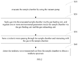
- a method for detecting a gas based on terahertz spectroscopy by using the apparatus includes: evacuating the sample chamber by using the vacuum pump; feeding the gas into the evacuated sample chamber via the gas feeding unit, and regulating one or more environmental parameters inside the sample chamber via one or more of the gas feeding unit, the gas outputting unit, the humidity regulation device, and the temperature regulation device; having the terahertz wave passing through the sample chamber and interacting with the gas in the sample chamber; and detecting the terahertz wave transmitted out from the sample chamber to obtain a terahertz spectrum.
- the method further includes closing the gas feeding unit and the gas outputting unit, thereby obtaining a gas flow static environment in the sample chamber during the detecting the terahertz wave.
- the detecting the terahertz wave is proceeded during the gas flowing through the sample chamber thereby obtaining a gas flow dynamic environment in the sample chamber during the detecting the terahertz wave.
- the regulating one or more environmental parameters inside the sample chamber includes regulating a gas composition, a concentration of a target gas component, and/or a pressure in the sample chamber via the plurality of gas feeding valves.
- the detecting the terahertz wave is proceeded during the regulating the gas composition, the concentration of the target gas component, and/or the pressure in the sample chamber.
- the regulating one or more environmental parameters inside the sample chamber includes regulating the humidity in the sampling chamber via the humidity regulation device.
- the regulating one or more environmental parameters inside the sample chamber includes regulating the temperature in the sampling chamber via the temperature regulation device.
- the environmental parameters inside the sample chamber can be regulated to investigate the influences of one or more of environmental parameters on the gas detection result to reduce a background noise of the terahertz spectrum, which is favorable to the quantitative analysis and the qualitative analysis of the gas.
- FIG. 1 is a schematic structural view of a gas detecting apparatus based on terahertz spectroscopy according to an embodiment of the present disclosure.
- FIG. 2 is flowchart of a method for gas detecting based on terahertz spectroscopy according to an embodiment of the present disclosure.
- the detection of a terahertz spectrum of target gas in a natural environment can be affected by environmental factors such as humidity, wind speed, wind direction, and composition of air. It is difficult to simulate the actual environment in a laboratory to study the target gas terahertz spectrum in a natural environment.
- the apparatus includes a gas feeding unit 100 , a sample chamber 200 , a vacuum pump (for example, a molecular pump) 300 , and a gas outputting unit 400 .
- the apparatus can further include one or more of a humidity regulation device 500 , a temperature regulation device 600 , a pressure gauge 700 , and an anemometer (for example, a miniature anemorumbometer) 800 .
- the apparatus includes both the humidity regulation device 500 and the temperature regulation device 600 .
- the sample chamber 200 can be connected to the gas feeding unit 100 and the gas outputting unit 400 , respectively.
- the sample chamber 200 has two opposite openings. One opening of the sample chamber 200 is connected to the gas feeding unit 100 , and the other opening of the sample chamber 200 is connected to the gas outputting unit 400 .
- the gas feeding unit 100 can control the feeding of gas into the sample chamber 200 .
- the gas feeding unit 100 can include a gas feeding tube connected to the sample chamber 200 and a gas feeding valve 120 disposed on the gas feeding tube.
- the gas feeding valve can regulate an amount and/or a flow rate of the gas fed into the sample chamber 200 via the gas feeding tube.
- the gas fed into the sample chamber 200 can be a single-component gas or a multi-component gas.
- the gas outputting unit 400 can control the output of the gas from the sample chamber 200 .
- the gas outputting unit 400 can include a gas outputting tube 410 connected to the sample chamber 200 and a gas outputting valve 420 disposed on the gas outputting tube 410 .
- the gas outputting valve 420 can regulate an amount and/or a flow rate of the gas output from the sample chamber 200 via the gas outputting tube 410 .
- the apparatus in the present disclosure can achieve a static detection and/or a dynamic detection by controlling the gas feeding valve and the gas outputting valve 420 .
- the gas in the sample chamber can be in a static state, and the static detection of the terahertz wave can be performed in the gas static state.
- the gas in the sample chamber can be in a flowing state and the dynamic detection of the terahertz wave can be performed in the gas flowing state.
- the dynamic detection can simulate an actual detection under windy condition in a natural environment.
- a pressure in the sample chamber 200 can also be regulated by regulating the amounts and/or the flow rates of the gas fed into and/or output from the sample chamber 200 through the gas feeding valve and/or the gas outputting valve 420 .
- the gas feeding tube can include a main gas feeding tube 110 and a plurality of branch gas feeding tubes 112 configured to convey different gas components.
- One end of the main gas feeding tube 110 can be connected to the sample chamber 200 , and the other end of the main gas feeding tube 110 can be connected to the plurality of branch gas feeding tubes 112 , respectively.
- the number of the gas feeding valves can be more than one, and the plurality of gas feeding valves 120 are disposed on the plurality of branch gas feeding tubes 112 , respectively.
- the plurality of branch gas feeding tubes 112 can be in fluid communication with different gas component sources.
- One or more gas components can be provided into the main gas feeding tube 110 via the plurality of branch gas feeding tubes 120 , mixed in the main gas feeding tube 110 , and then fed into the sample chamber 200 .
- a composition, the amount, and/or the flow rate of the gas fed into the sample chamber 200 can be regulated.
- the gas feeding unit 100 can further include a plurality of gas flowmeters (not shown) disposed on the plurality of gas feeding valves 120 , respectively, to measure a flow rate of each gas component provided into the main gas feeding tube 110 .
- the numbers of the branch gas feeding tubes 112 , the gas feeding valves 120 , and the gas flowmeters are not limited herein and can be set according to actual needs. Both the gas feeding valve 120 and the gas outputting valve 420 can be one-way valves.
- one of the branch gas feeding tubes 112 can be in fluid communication with a source 101 of a background gas component.
- Another of the branch gas feeding tubes 112 can be in fluid communication with a source 102 of one target gas component (e.g., a first gas source).
- a third of the branch gas feeding tubes 112 can be in fluid communication with a source 103 of another target gas component (e.g., a second gas source).
- the background gas component refers to a gas component substantially has no absorption to the terahertz wave.
- the background gas can be nitrogen gas.
- the target gas component refers to a gas component to be detected.
- the target gas component can absorb the terahertz wave.
- the background gas component can be used to regulate a pressure in the sample chamber 200 .
- the background gas component can also be used to form a dynamic detection environment by flowing through the sample chamber 200 from the gas feeding tube to the gas outputting tube 410 .
- the pressure gauge 700 can be disposed on the sample chamber 200 to measure the pressure in the sample chamber 200 in real time.
- the pressure gauge 700 can also be configured to display a real-time pressure in the sample chamber 200 .
- the pressure gauge 700 can include a pressure gauge switch. The pressure gauge 700 can be turned on or turned off via the pressure gauge switch to initiate or terminate the pressure measurement.
- the anemometer 800 can be disposed on the sample chamber 200 to measure an actual flow rate of the gas flowing through the sample chamber 200 .
- the actual flow rate of the gas flowing through the sample chamber 200 can be used to verify a theory flow rate of the gas flowing through the sample chamber 200 calculated from the flow rate of each gas component supplied via the plurality of branch gas feeding tubes 120 , the flow rate of the gas output from the sample chamber 200 , and a volume of the sample chamber 200 .
- the anemometer 800 can include an anemometer switch.
- the anemometer 800 can be turned on or turned off via the anemometer switch to initiate or terminate the measurement for the flow rate of the gas flowing through the sample chamber 200 .
- the anemometer 800 can display a real-time flow rate of the gas measured.
- the vacuum pump 300 can be connected to the sample chamber 200 .
- the vacuum pump 300 is configured to evacuate the sample chamber 200 before the detection to ensure the accuracy of the detection.
- the vacuum pump 300 can include a vacuum switch.
- the vacuum pump 300 can be turned on or turned off via the vacuum switch to initiate or terminate the evacuation operation of the vacuum pump 300 .
- the humidity regulation device 500 can be connected to the sample chamber 200 and can regulate humidity in the sample chamber 200 .
- the humidity regulation device 500 can include a moisture supplying device 510 and a humidity regulating valve 520 .
- the moisture supplying device 510 can be in fluid communication with the sample chamber 200 to supply a liquid water and/or water vapor to the sample chamber 200 .
- the humidity regulating valve 520 can be disposed between the humidity regulation device 500 and the sample chamber 200 to regulate an amount and/or a flow rate of the liquid water and/or the water vapor supplied to the sample chamber 200 , so as to regulate the humidity in the sample chamber 200 .
- the humidity regulating valve 520 can be a one-way valve.
- the humidity regulation device 500 can further include a filter 530 disposed between the moisture supply device 510 and the sample chamber 200 .
- the filter 530 is configured to filter out an impurity from the liquid water and/or the water vapor supplied to the sample chamber 200 to ensure the accuracy of the detection.
- the humidity regulation device 500 can further include a hygrometer 540 .
- the hygrometer 540 can be disposed on the sample chamber 200 to measure the humidity in the sample chamber 200 .
- the hygrometer 540 can also be configured to display the real-time humidity in the sample chamber 200 .
- the hygrometer 540 can include a hygrometer switch. The hygrometer 540 can be turned on or turned off via the hygrometer switch to initiate or terminate the humidity measurement.
- the temperature regulation device 600 can regulate temperature in the sample chamber 200 .
- the temperature regulation device 600 can include a heater 610 disposed on the sample chamber 200 to heat the gas in the sample chamber 200 and regulate the temperature in the sample chamber 200 .
- the heater 610 can be any heater known in the art.
- the heater 610 includes a heating plate attached on an inner wall of the sample chamber 200 .
- the heater 610 can include a heater switch. The heater 610 can be turned on or turned off via the heater switch to initiate or terminate the heating operation.
- the temperature regulation device 600 can further include a thermometer 620 disposed on the sample chamber 200 to measure the temperature in the sample chamber 200 .
- the thermometer 620 can be configured to display the real-time temperature in the sample chamber 200 .
- the thermometer 620 can be any appropriate thermometer known in the art.
- the thermometer 620 is a patch thermometer attached on an outer wall of the sample chamber 200 .
- the thermometer 620 can include a thermometer switch. The thermometer 620 can be turned on or turned off via the thermometer switch to initiate or terminate the temperature measurement.
- a shape of the sample chamber 200 is not limited herein and can be selected according to needs.
- the shape of the sample chamber 200 may depend on the specific structure of the apparatus and the installation space of the sample chamber 200 .
- the sample chamber 200 can have a cylindrical shape.
- the sample chamber 200 can have its central axis parallel to a horizontal plane or tilted to the horizontal plane.
- the apparatus can further include a terahertz wave generating unit 910 and a terahertz wave detecting unit 920 .
- a terahertz wave 901 generated by the terahertz wave generating unit 910 can pass through the sample chamber 200 to interact with (for example, the terahertz wave with a certain frequency is to be absorbed by) the gas in the sample chamber 200 .
- a terahertz wave 902 interacted with the gas can exit from the sample chamber 200 and be received by the terahertz wave detecting unit 920 to obtain the terahertz spectrum of the gas in the sample chamber 200 .
- the quantitative analysis and the qualitative analysis of the gas can be achieved based on the terahertz spectroscopy.
- the static detection and the dynamic detection can be performed by controlling the gas feeding unit 100 and the gas outputting unit 400 .
- a single-factor detection and a multi-factor detection can be performed by regulating one or more of environmental parameters inside the sample chamber 200 via one or more of the gas feeding unit 100 , the gas outputting unit 400 , the humidity regulation device 500 , the temperature regulation device 600 , the pressure gage 700 , and the anemometer 800 .
- the humidity in the sample chamber 200 can be regulated via the humidity regulation device 500
- the temperature in the sample chamber 200 can be regulated via the temperature regulation device 600
- the pressure in the sample chamber 200 can be regulated via the mass concentration and the composition of the gas in the sample chamber 200
- the flow rate of the gas flowing through the sample chamber 200 can be regulated via the gas feeding unit 100 and/or the gas outputting unit 400 .
- the influences of one or more of environmental parameters on the gas detection result can be investigated, which can be utilized to simulate the natural environment of the actual detection.
- the method can include:
- All the valves and switches can be in a close state in S 10 .
- the evacuation operation can be initiated by opening the vacuum switch. After the sample chamber 200 is evacuated, the evacuation operation can be terminated by closing the vacuum switch.
- S 20 can include:
- the static detection of the terahertz wave can be performed in the static environment.
- the gas outputting valve 420 can be maintained in the close state throughout the static detection.
- S 211 can specifically include:
- the composition of the gas in the sample chamber 200 can be regulated by regulating a ratio of the amount of the background gas component to the amount of the target gas component fed into the sampling chamber 200 via the corresponding gas feed valve(s).
- the composition of the gas in the sample chamber 200 can be further regulated by regulating ratios of amounts of a plurality of target gas components, for example, a ratio of the amount of the first target gas component to the amount of the second target gas component, via the corresponding gas feed valves.
- the mass concentration of the target gas refers to a ratio of the mass of the target gas fed into the sample chamber 200 to the volume of the sample chamber 200 .
- the mass concentration of the target gas in the sample chamber 200 can be regulated by regulating the amount of the target gas fed into the sample chamber 200 via the corresponding gas feed valve(s).
- the pressure in the sample chamber 200 can be regulated by regulating the amounts of the background gas component and the target gas component fed into the sampling chamber 200 via the corresponding gas feed valves.
- the pressure in the sampling chamber 200 is proportional to the amount of the gas fed into the sampling chamber 200 and the mass concentration of the gas in the sampling chamber 200 .
- the mass concentration of the gas in the sampling chamber 200 can be calculated according to an equation (I):
- c denotes the mass concentration of the gas in the sampling chamber 200
- n denotes the mass of the gas in the sampling chamber 200
- V 0 denotes the volume of the sampling chamber 200 .
- the mass of the gas fed into the sampling chamber 200 can be calculated according to an equation (II):
- V denotes the amount (volume) of the gas fed into the sampling chamber 200
- V m denotes a molar volume of the gas under standard atmospheric pressure
- n 1 and n 2 denotes a mass of a first gas component (for example, the target gas component) and a mass of a second gas component (for example, the background gas component) in the sampling chamber 200 , respectively.
- the calculation methods of n 1 and n 2 can be referred to the equation (II).
- the amount of each gas component can be regulated according to the desired mass concentration of the gas in the sampling chamber 200 and/or the desired pressure in the sampling chamber 200 .
- S 20 can further include:
- a single-factor static detection can be performed.
- a multi-factor static detection can be performed.
- the S 20 can include:
- the dynamic detection can be performed in the dynamic environment.
- the flow rate of the gas flowing through the sample chamber 200 can be regulated by regulating the flow rate of the background gas component, the flow rate of the target gas component, and the flow rate of the gas output from the sample chamber 200 by regulating the corresponding gas feeding valves 120 and the gas outputting valve 420 .
- the plurality of flowmeters can be used to monitor the corresponding flow rates.
- S 221 can further include:
- the composition of the gas in the sample chamber 200 regulating the composition of the gas in the sample chamber 200 , the mass concentration of the target gas component in the sample chamber 200 , the flow rate of the gas flowing through the sample chamber 200 , and/or the pressure in the sample chamber 200 via the plurality of gas feeding valves 120 and the gas outputting tube 420 .
- composition of the gas in the sample chamber 200 , the mass concentration of the target gas component in the sample chamber 200 , the flow rate of the gas flowing through the sample chamber 200 , and/or the pressure in the sample chamber 200 can be regulated by regulating the flow rate of each gas component entering into the main gas feeding tube 110 and the flow rate of gas output from the sample chamber 200 .
- the single-factor static/dynamic detection can be achieved by regulating one environmental parameter while the other environmental parameters can be constant, so that the influence of the parameter regulated during the static/dynamic detection on the terahertz spectrum of the target gas can be obtained.
- a multi-factor static/dynamic detection can be achieved by regulating two or more environmental parameters, while the other environmental parameters can be constant, so that the interaction effect of two or more parameters during the static/dynamic detection on the terahertz spectrum of the target gas can be obtained.
- the influences of one or more of environmental parameters and interaction effect thereof on the gas detection result can be utilized to reduce a background noise of the terahertz spectrum and is favorable to the quantitative analysis and the qualitative analysis of the gas.
- the regulating the humidity in the sample chamber 200 can include regulating the amount and/or the flow rate of the liquid water and/or water vapor supplied to the sample chamber 200 via the humidity regulating valve 520 .
- the regulating the humidity in the sample chamber 200 can further include turning on the hygrometer switch to obtain the real-time humidity in the sample chamber 200 and regulating the amount and/or the flow rate of the liquid water and/or water vapor supplied to the sample chamber 200 according to the real-time humidity and the expected humidity in the sample chamber 200 .
- the regulating the temperature in the sample chamber 200 can further include: turning on the heater switch to regulate the temperature in the sample chamber 200 .
- the regulating the temperature in the sample chamber 200 can further include turning on the thermometer switch to measure and display the real-time temperature in the sample chamber 200 , and regulating the heater according to the real-time temperature and the expected temperature in the sample chamber 200 .
- the regulating the pressure in the sample chamber 200 can include: regulating the amount and/or the flow rate of each gas component via each of the plurality of gas feeding valves 120 , and/or regulating the amount and/or the flow rate of the gas output from the sample chamber 200 via the gas outputting valve 420 .
- the regulating the pressure in the sample chamber 200 can further include: turning on the pressure gage switch to measure and display the real-time pressure in the sample chamber 200 , and regulating the amount and/or the flow rate of each gas component and/or regulating the amount and/or the flow rate of the gas output from the sample chamber 200 according to the real-time pressure and the expected pressure in the sample chamber 200 .
- the regulating the flow rate of the gas flowing through the sample chamber 200 can include: regulating the flow rate of each gas component via each of the plurality of gas feeding valves 120 , and/or regulating the flow rate of the gas output from the sample chamber 200 via the gas outputting valve 420 .
- the regulating the flow rate of the gas flowing through the sample chamber 200 can further include: turning on the anemometer to measure and display the real-time flow rate of the gas flowing through the sample chamber 200 , and regulating the flow rate of each gas component and/or regulating the flow rate of the gas output from the sample chamber 200 according to the real-time flow rate of the gas flowing through the sample chamber 200 and the expected flow rate of the gas flowing through the sample chamber 200 .
- the terahertz wave can enter into the sample chamber 200 with the regulated environment, interact with the gas, exit from the sample chamber 200 , and arrive at the terahertz wave detecting unit to generate a terahertz spectrum of the gas in the regulated environment of the sample chamber 200 .
- the quantitative analysis and the qualitative analysis of the gas can be achieved based on the terahertz spectrum and the environmental parameters.
- the environmental parameters inside the sample chamber 200 can be regulated via one or more of the gas feeding unit 100 , the gas outputting unit 400 , the humidity regulation device 500 , the temperature regulation device 600 , the pressure gauge 700 , and the anemometer 800 .
- the environmental parameters can include one or more of the humidity, the temperature, the pressure in the sample chamber 200 , and the composition, the mass concentration, and the flow rate of the gas in the sample chamber 200 .
- a single-factor static detection, a multi-factor static detection, a single-factor dynamic detection, and a multi-factor dynamic detection can be achieved. Therefore, the influences of one or more of environmental parameters on the gas detection result can be investigated and utilized to reduce a background noise of the terahertz spectrum, which is favorable to the quantitative analysis and the qualitative analysis of the gas.
- each step may be displayed in succession as indicated, these steps may not necessarily be executed in succession in the order indicated by the arrows of FIG. 1 . Unless expressly described herein, the execution of these steps may not be limited to a strict order; instead, the steps can be executed in another order. In addition, at least some steps may include multiple sub-steps or multiple stages. These sub-steps or stages may not necessarily be executed or completed at the same moment, but can be executed at different times, and the order of execution thereof may also not necessarily be in succession, but can be executed in turn or alternately with at least some other steps or sub-steps or stages of other steps.
Landscapes
- Physics & Mathematics (AREA)
- Spectroscopy & Molecular Physics (AREA)
- Health & Medical Sciences (AREA)
- General Physics & Mathematics (AREA)
- Life Sciences & Earth Sciences (AREA)
- Chemical & Material Sciences (AREA)
- Analytical Chemistry (AREA)
- Biochemistry (AREA)
- General Health & Medical Sciences (AREA)
- Immunology (AREA)
- Pathology (AREA)
- Toxicology (AREA)
- Investigating Or Analysing Materials By Optical Means (AREA)
- Sampling And Sample Adjustment (AREA)
Applications Claiming Priority (2)
| Application Number | Priority Date | Filing Date | Title |
|---|---|---|---|
| CN201910430311.4 | 2019-05-22 | ||
| CN201910430311.4A CN110132885A (zh) | 2019-05-22 | 2019-05-22 | 气体太赫兹光谱探测装置和方法 |
Publications (2)
| Publication Number | Publication Date |
|---|---|
| US20200371021A1 US20200371021A1 (en) | 2020-11-26 |
| US11215554B2 true US11215554B2 (en) | 2022-01-04 |
Family
ID=67572487
Family Applications (1)
| Application Number | Title | Priority Date | Filing Date |
|---|---|---|---|
| US16/880,067 Active US11215554B2 (en) | 2019-05-22 | 2020-05-21 | Gas detecting apparatus and method based on terahertz spectroscopy |
Country Status (3)
| Country | Link |
|---|---|
| US (1) | US11215554B2 (zh) |
| CN (1) | CN110132885A (zh) |
| WO (1) | WO2020233029A1 (zh) |
Families Citing this family (4)
| Publication number | Priority date | Publication date | Assignee | Title |
|---|---|---|---|---|
| CN110132885A (zh) * | 2019-05-22 | 2019-08-16 | 清华大学 | 气体太赫兹光谱探测装置和方法 |
| CN110487744A (zh) * | 2019-09-18 | 2019-11-22 | 华东交通大学 | 一种用于太赫兹光谱检测设备实验的辅助装置 |
| CN111678885A (zh) * | 2020-05-29 | 2020-09-18 | 清华大学 | 化学反应观测系统及方法 |
| CN114797516A (zh) * | 2021-01-29 | 2022-07-29 | 陕西青朗万城环保科技有限公司 | 一种多成分气体的发生方法及其控制系统 |
Citations (7)
| Publication number | Priority date | Publication date | Assignee | Title |
|---|---|---|---|---|
| CN104713596A (zh) | 2015-01-07 | 2015-06-17 | 北京科技大学 | 一种太赫兹实验环境的智能监测系统及监测方法 |
| US20150260695A1 (en) * | 2014-03-17 | 2015-09-17 | Prism Analytical Technologies, Inc. | Process and system for rapid sample analysis |
| CN105404228A (zh) | 2015-12-24 | 2016-03-16 | 北京农业智能装备技术研究中心 | 一种太赫兹实验系统及方法 |
| US20160132617A1 (en) * | 2014-11-11 | 2016-05-12 | Spectrasensors, Inc. | Target Analyte Detection and Quantification in Sample Gases With Complex Background Compositions |
| CN106647883A (zh) | 2016-10-31 | 2017-05-10 | 深圳市太赫兹科技创新研究院 | 太赫兹试验环境监控系统 |
| CN108181261A (zh) | 2017-12-27 | 2018-06-19 | 上海理工大学 | 基于太赫兹时域光谱检测混合气体各组分含量的装置 |
| CN109283141A (zh) | 2018-11-02 | 2019-01-29 | 河北大学 | 一种去除水汽干扰的呼出气体光谱检测系统及方法 |
Family Cites Families (1)
| Publication number | Priority date | Publication date | Assignee | Title |
|---|---|---|---|---|
| CN110132885A (zh) * | 2019-05-22 | 2019-08-16 | 清华大学 | 气体太赫兹光谱探测装置和方法 |
-
2019
- 2019-05-22 CN CN201910430311.4A patent/CN110132885A/zh active Pending
- 2019-11-20 WO PCT/CN2019/119701 patent/WO2020233029A1/zh active Application Filing
-
2020
- 2020-05-21 US US16/880,067 patent/US11215554B2/en active Active
Patent Citations (7)
| Publication number | Priority date | Publication date | Assignee | Title |
|---|---|---|---|---|
| US20150260695A1 (en) * | 2014-03-17 | 2015-09-17 | Prism Analytical Technologies, Inc. | Process and system for rapid sample analysis |
| US20160132617A1 (en) * | 2014-11-11 | 2016-05-12 | Spectrasensors, Inc. | Target Analyte Detection and Quantification in Sample Gases With Complex Background Compositions |
| CN104713596A (zh) | 2015-01-07 | 2015-06-17 | 北京科技大学 | 一种太赫兹实验环境的智能监测系统及监测方法 |
| CN105404228A (zh) | 2015-12-24 | 2016-03-16 | 北京农业智能装备技术研究中心 | 一种太赫兹实验系统及方法 |
| CN106647883A (zh) | 2016-10-31 | 2017-05-10 | 深圳市太赫兹科技创新研究院 | 太赫兹试验环境监控系统 |
| CN108181261A (zh) | 2017-12-27 | 2018-06-19 | 上海理工大学 | 基于太赫兹时域光谱检测混合气体各组分含量的装置 |
| CN109283141A (zh) | 2018-11-02 | 2019-01-29 | 河北大学 | 一种去除水汽干扰的呼出气体光谱检测系统及方法 |
Also Published As
| Publication number | Publication date |
|---|---|
| CN110132885A (zh) | 2019-08-16 |
| WO2020233029A1 (zh) | 2020-11-26 |
| US20200371021A1 (en) | 2020-11-26 |
Similar Documents
| Publication | Publication Date | Title |
|---|---|---|
| US11215554B2 (en) | Gas detecting apparatus and method based on terahertz spectroscopy | |
| CN103852437B (zh) | 一种温室气体排放通量的中红外光谱测量系统及方法 | |
| US8424367B2 (en) | Systems and methods for measurement of gas permeation through polymer films | |
| US9234905B2 (en) | Method of calibrating and calibration apparatus for a moisture concentration measurement apparatus | |
| CN107486046A (zh) | 高浓度有机物标准混合气体发生装置及其使用方法 | |
| CN102707017A (zh) | 用于检测气体监测系统完整性、可靠性的测试系统 | |
| Li et al. | Test gas generation from pure liquids: an application-oriented overview of methods in a nutshell | |
| US20200124766A1 (en) | Apparatus and method for radio-sonde temperature and humidity calibration using upper air simulation technology | |
| CN102175817B (zh) | 水汽氢氧稳定同位素通量的模拟装置与用途 | |
| CN104006929A (zh) | 基于限压-分流法的大气环境下的质谱单点检漏系统及方法 | |
| Kaiser et al. | Intercomparison of Hantzsch and fiber-laser-induced-fluorescence formaldehyde measurements | |
| US8171775B2 (en) | Material permeance measurement system and method | |
| Susaya et al. | The controlling effect of temperature in the application of permeation tube devices in standard gas generation | |
| Hurst et al. | A dynamic calibration technique for temperature programmed desorption spectroscopy | |
| CN102039096B (zh) | 常压室温可挥发性液体动态配气系统及其配气方法 | |
| CN109060931A (zh) | 水汽分析仪校准装置及校准方法 | |
| JPH01199133A (ja) | ガス発生装置及びその発生方法 | |
| CN201152868Y (zh) | 四极质谱计相对灵敏度校准系统 | |
| Brewer et al. | A dynamic gravimetric standard for trace water | |
| CN106441702A (zh) | 一种双小孔质谱计校准装置及方法 | |
| CN104165921A (zh) | 间歇式超低压表面反应装置 | |
| Sairanen et al. | A calibration system for reference radiosondes that meets GRUAN uncertainty requirements | |
| RU2446005C1 (ru) | Устройство для приготовления многокомпонентных газовых смесей | |
| KR20020043569A (ko) | 가스내에서 수증기표준을 발생시키기 위한 장치 및 방법 | |
| CN113960248A (zh) | 一种痕量气体检测设备测试工装和样品配制方法 |
Legal Events
| Date | Code | Title | Description |
|---|---|---|---|
| AS | Assignment |
Owner name: TSINGHUA UNIVERSITY, CHINA Free format text: ASSIGNMENT OF ASSIGNORS INTEREST;ASSIGNORS:ZHENG, XIAO-PING;ZHANG, SHAN;GENG, HUA;AND OTHERS;SIGNING DATES FROM 20200424 TO 20200507;REEL/FRAME:052723/0177 |
|
| FEPP | Fee payment procedure |
Free format text: ENTITY STATUS SET TO UNDISCOUNTED (ORIGINAL EVENT CODE: BIG.); ENTITY STATUS OF PATENT OWNER: SMALL ENTITY |
|
| FEPP | Fee payment procedure |
Free format text: ENTITY STATUS SET TO SMALL (ORIGINAL EVENT CODE: SMAL); ENTITY STATUS OF PATENT OWNER: SMALL ENTITY |
|
| STPP | Information on status: patent application and granting procedure in general |
Free format text: APPLICATION DISPATCHED FROM PREEXAM, NOT YET DOCKETED |
|
| STPP | Information on status: patent application and granting procedure in general |
Free format text: DOCKETED NEW CASE - READY FOR EXAMINATION |
|
| STPP | Information on status: patent application and granting procedure in general |
Free format text: NON FINAL ACTION MAILED |
|
| STPP | Information on status: patent application and granting procedure in general |
Free format text: RESPONSE TO NON-FINAL OFFICE ACTION ENTERED AND FORWARDED TO EXAMINER |
|
| STPP | Information on status: patent application and granting procedure in general |
Free format text: NOTICE OF ALLOWANCE MAILED -- APPLICATION RECEIVED IN OFFICE OF PUBLICATIONS |
|
| STPP | Information on status: patent application and granting procedure in general |
Free format text: PUBLICATIONS -- ISSUE FEE PAYMENT RECEIVED |
|
| STPP | Information on status: patent application and granting procedure in general |
Free format text: PUBLICATIONS -- ISSUE FEE PAYMENT VERIFIED |
|
| STCF | Information on status: patent grant |
Free format text: PATENTED CASE |