US11215403B2 - High performance two-phase cooling apparatus - Google Patents
High performance two-phase cooling apparatus Download PDFInfo
- Publication number
- US11215403B2 US11215403B2 US16/543,428 US201916543428A US11215403B2 US 11215403 B2 US11215403 B2 US 11215403B2 US 201916543428 A US201916543428 A US 201916543428A US 11215403 B2 US11215403 B2 US 11215403B2
- Authority
- US
- United States
- Prior art keywords
- wicking structure
- ground plane
- region
- thermal ground
- vapor
- Prior art date
- Legal status (The legal status is an assumption and is not a legal conclusion. Google has not performed a legal analysis and makes no representation as to the accuracy of the status listed.)
- Active
Links
Images


Classifications
-
- F—MECHANICAL ENGINEERING; LIGHTING; HEATING; WEAPONS; BLASTING
- F28—HEAT EXCHANGE IN GENERAL
- F28D—HEAT-EXCHANGE APPARATUS, NOT PROVIDED FOR IN ANOTHER SUBCLASS, IN WHICH THE HEAT-EXCHANGE MEDIA DO NOT COME INTO DIRECT CONTACT
- F28D15/00—Heat-exchange apparatus with the intermediate heat-transfer medium in closed tubes passing into or through the conduit walls ; Heat-exchange apparatus employing intermediate heat-transfer medium or bodies
- F28D15/02—Heat-exchange apparatus with the intermediate heat-transfer medium in closed tubes passing into or through the conduit walls ; Heat-exchange apparatus employing intermediate heat-transfer medium or bodies in which the medium condenses and evaporates, e.g. heat pipes
- F28D15/04—Heat-exchange apparatus with the intermediate heat-transfer medium in closed tubes passing into or through the conduit walls ; Heat-exchange apparatus employing intermediate heat-transfer medium or bodies in which the medium condenses and evaporates, e.g. heat pipes with tubes having a capillary structure
- F28D15/046—Heat-exchange apparatus with the intermediate heat-transfer medium in closed tubes passing into or through the conduit walls ; Heat-exchange apparatus employing intermediate heat-transfer medium or bodies in which the medium condenses and evaporates, e.g. heat pipes with tubes having a capillary structure characterised by the material or the construction of the capillary structure
-
- F—MECHANICAL ENGINEERING; LIGHTING; HEATING; WEAPONS; BLASTING
- F28—HEAT EXCHANGE IN GENERAL
- F28D—HEAT-EXCHANGE APPARATUS, NOT PROVIDED FOR IN ANOTHER SUBCLASS, IN WHICH THE HEAT-EXCHANGE MEDIA DO NOT COME INTO DIRECT CONTACT
- F28D15/00—Heat-exchange apparatus with the intermediate heat-transfer medium in closed tubes passing into or through the conduit walls ; Heat-exchange apparatus employing intermediate heat-transfer medium or bodies
- F28D15/02—Heat-exchange apparatus with the intermediate heat-transfer medium in closed tubes passing into or through the conduit walls ; Heat-exchange apparatus employing intermediate heat-transfer medium or bodies in which the medium condenses and evaporates, e.g. heat pipes
- F28D15/0233—Heat-exchange apparatus with the intermediate heat-transfer medium in closed tubes passing into or through the conduit walls ; Heat-exchange apparatus employing intermediate heat-transfer medium or bodies in which the medium condenses and evaporates, e.g. heat pipes the conduits having a particular shape, e.g. non-circular cross-section, annular
-
- F—MECHANICAL ENGINEERING; LIGHTING; HEATING; WEAPONS; BLASTING
- F28—HEAT EXCHANGE IN GENERAL
- F28F—DETAILS OF HEAT-EXCHANGE AND HEAT-TRANSFER APPARATUS, OF GENERAL APPLICATION
- F28F21/00—Constructions of heat-exchange apparatus characterised by the selection of particular materials
- F28F21/08—Constructions of heat-exchange apparatus characterised by the selection of particular materials of metal
- F28F21/081—Heat exchange elements made from metals or metal alloys
-
- F—MECHANICAL ENGINEERING; LIGHTING; HEATING; WEAPONS; BLASTING
- F28—HEAT EXCHANGE IN GENERAL
- F28F—DETAILS OF HEAT-EXCHANGE AND HEAT-TRANSFER APPARATUS, OF GENERAL APPLICATION
- F28F2260/00—Heat exchangers or heat exchange elements having special size, e.g. microstructures
Definitions
- This invention relates to cooling of semiconductor devices, and, more particularly, to cooling systems to cool semiconductor and other devices.
- TGPs thin thermal ground planes
- Two-phase cooling devices are a class of devices that can transfer heat with very high efficiency, and may include: heat pipes, thermal ground planes, vapor chambers and thermosiphons, and the like.
- the present application provides two-phase cooling devices including at least three substrates.
- one or more of the substrates is formed from microfabricated metal, such as but not limited to titanium, aluminum, copper, or stainless steel.
- the substrate may be formed as a thermal ground plane structure suitable for use in electronic devices.
- the two-phase device may comprise a predetermined amount of at least one suitable working fluid, where the working fluid adsorbs or rejects heat by changing phases between liquid and vapor.
- the present application may provide two-phase cooling devices including a metal, such as but not limited to titanium, aluminum, copper, or stainless steel, substrate comprising a plurality of etched microstructures, forming a wicking structure wherein one or more of the microstructures have a height of between about 1-1000 micrometers, a width of between about 1-1000 micrometers, and a spacing of between about 1-1000 micrometers.
- a vapor cavity may be in communication with the plurality of metal microstructures.
- at least one intermediate substrate may be in communication with the wicking structure and the vapor region.
- a fluid may be contained within the wicking structure and vapor cavity for transporting thermal energy from one region of the thermal ground plane to another region of the thermal ground plane, wherein the fluid may be driven by capillary forces within the wicking structure.
- the cooling device can be configured for high capillary force in the wicking structure, to support large pressure differences between the liquid and vapor phases, while minimizing viscous losses of the liquid flowing in the wicking structure.
- the cooling device may be a thermal ground plane which can be made very thin, and could possibly transfer more thermal energy than can be achieved by earlier TGP's.
- different structural components could be located in an evaporator region, an adiabatic region and a condenser region.
- an evaporator region may contain an intermediate substrate that comprises a plurality of microstructures that when mated with the wicking structure form high aspect ratio structures.
- the intermediate substrate features are interleaved with the wicking structure features to increase the effective aspect ratio of the wicking structure.
- an adiabatic region may contain an intermediate substrate positioned in close proximity to the wicking structure to separate the vapor in the vapor chamber from the liquid in the wicking structure.
- a condenser region may contain an intermediate substrate that has large openings (compared to the microstructure) so that the wicking structure is in direct communication with the vapor chamber.
- a condenser region might not contain an intermediate substrate so that the wicking structure is in direct communication with the vapor chamber.
- FIG. 1 is an illustrative embodiment of an earlier titanium-based thermal ground plane, comprising a titanium substrate with a wicking structure, a backplane, and a vapor chamber;
- FIG. 2 is an illustrative embodiment of earlier titanium substrates with a wicking structure: (A) the wicking structure comprises pillars, (B) the wicking structure comprises channels or grooves;
- FIG. 3 is an illustrative embodiment of a metal-based thermal ground plane with an intermediate substrate in communication with a wicking structure and a vapor chamber.
- the intermediate layer could comprise microstructures.
- (A) shows a profile view depicting components of an embodiment
- (B) shows an exploded view of structural components of an embodiment
- FIG. 4 depicts structural components according to an illustrative embodiment where the different structural components are located in an evaporator region, an adiabatic region and a condenser region:
- A shows an evaporator region of an embodiment where the intermediate substrate comprises a plurality of microstructures that are interleaved with the wicking structure
- B shows an adiabatic region of an embodiment where the intermediate substrate is positioned in close proximity to the wicking
- C shows a condenser region of an embodiment where the wicking structure is in direct communication with the vapor chamber
- D shows detail of an embodiment of an intermediate substrate;
- FIG. 5 is an illustrative embodiment of profile views of structural components of an embodiment where the structures are non-wetted (i.e. dry) and wetted by a liquid: (A) non-wetted structural components in the evaporator region, (B) wetted structural components in the evaporator region, (C) non-wetted structural components in the adiabatic region, (D) wetted structural components in the adiabatic region, (E) non-wetted structural components in the condenser region, (F) wetted structural components in the condenser region;
- A non-wetted structural components in the evaporator region
- B wetted structural components in the evaporator region
- C non-wetted structural components in the adiabatic region
- D wetted structural components in the adiabatic region
- E non-wetted structural components in the condenser region
- F wetted structural components in the condenser region
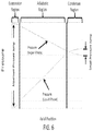
- FIG. 6 shows pressure profiles as a function of axial location for an illustrative embodiment of a thermal ground plane.
- the curves show the pressure of the vapor phase in the vapor chamber and the liquid phase in the wicking structure. In this case, the maximum pressure difference between the liquid and vapor phases occurs in the evaporator region. The minimum pressure difference between the vapor and liquid phases occurs in the condenser region;
- the evaporator is in the center, and there are adiabatic and condenser regions on each side;
- FIG. 8 compares maximum heat transfer for titanium-based thermal ground planes for different vapor temperatures. The comparison is between an earlier titanium thermal ground plane, and an illustrative embodiment of the current thermal ground plane using an intermediate substrate;
- FIG. 9 is an illustrative embodiment of a flow chart of the formation of one or more embodiments of the current Ti-based TGP (metal-based Thermal Ground Plane) in accordance with one or more embodiments;
- FIG. 10 is an illustrative embodiment of a flow chart of the formation of one or more embodiments of the current Ti-based TGP
- FIG. 11 shows illustrative embodiments of a wicking structure in communication with an intermediate substrate.
- the effective aspect ratio is defined as the ratio of the effective channel height, h, to the effective channel width, w:
- (A) shows an illustrative embodiment where the microstructures in the intermediate substrate are interleaved with the wicking structure,
- (B) shows an alternative embodiment where the microstructures in the intermediate substrate are positioned above the wicking structure;
- FIG. 12 is a perspective view an intermediate substrate with a plurality of supporting cross members
- FIG. 13 is a perspective view of an intermediate substrate with supporting cross members, wherein (A) the microstructures are in communication with cross-members and (B) wherein the microstructures and cross-members are positioned directly above the wicking structure; and
- FIG. 14 is a profile view of an illustration of a vapor chamber with one or more recessed regions.
- the thermal ground planes disclosed here could be used to provide efficient space utilization for cooling semiconductor devices in a large range of applications, including but not limited to aircraft, satellites, laptop computers, desktop computers, mobile devices, automobiles, motor vehicles, heating air conditioning and ventilation systems, and data centers.
- Microfabricated substrates can be used to make more robust, shock resistant two-phase cooling devices, which may be in the form of Thermal Ground Planes (TGPs).
- TGPs Thermal Ground Planes
- metal such as but not limited to titanium, aluminum, copper, or stainless steel substrates have been found suitable for TGPs.
- metal can depend upon the various applications and cost considerations. There are advantages to various metals. For example, copper offers the highest thermal conductivity of all the metals. Aluminum can be advantageous for applications where high thermal conductivity is important and weight might be important. Stainless steel could have advantageous in certain harsh environments.
- Titanium has many advantages. For example, titanium has a high fracture toughness, can be microfabricated and micromachined, can resist high temperatures, can resist harsh environments, can be bio-compatible. In addition, titanium-based thermal ground planes can be made light weight, relatively thin, and have high heat transfer performance. Titanium can be pulse laser welded. Since titanium has a high fracture toughness, it can be formed into thin substrates that resist crack and defect propagation. Titanium has a relatively low coefficient of thermal expansion of approximately 8.6 ⁇ 10 ⁇ 6 /K. The low coefficient of thermal expansion, coupled with thin substrates can help to substantially reduce stresses due to thermal mismatch. Titanium can be oxidized to form Nano Structured Titania (NST), which forms stable and super hydrophilic surfaces. In some embodiments, titanium (Ti) substrates with integrated Nano Structured Titania (NST) have been found suitable for TGP's.
- NST Nano Structured Titania
- Metals such as but not limited to titanium, aluminum, copper, or stainless steel, can be microfabricated with controlled characteristic dimensions (depth, width, and spacing) ranging from about 1-1000 micrometers, to engineer the wicking structure and intermediate substrate for optimal performance and customized for specific applications.
- controlled characteristic dimensions depth, width, and spacing
- the controlled characteristic dimensions could range from 10-500 micrometers, to engineer the wicking structure for optimal performance and customized for specific applications.
- titanium can be oxidized to form nanostructured titania (NST), which could provide super hydrophilic surfaces and thereby increase capillary forces, and enhance heat transfer.
- NST nanostructured titania
- the NST can be comprised of hair-like patterns with a nominal roughness of 200 nanometers (nm). In some embodiments, NST can have a nominal roughness of 1-1000 nm.
- aluminum can be oxidized to form hydrophilic nanostructures, to provide super hydrophilic coatings.
- sintered nanoparticles and/or microparticles could be used to provide super hydrophilic surfaces and thereby increase capillary forces, and enhance heat transfer.
- titanium can be coated on another type of substrate forming a titanium film.
- the titanium film can be oxidized to form nano-structured titania (NST), and thereby provide super hydrophilic surfaces.
- NST nano-structured titania
- Titanium is a material that can be microfabricated using cleanroom processing techniques, macro-machined in a machine shop, and hermetically packaged using a pulsed laser micro welding technique.
- the thermal ground plane is comprised of only titanium or titania as the structural material, the various components can be laser welded in place, without introducing contaminants, which could possibly produce non-condensable gasses, contribute to poor performance, and possibly lead to failure.
- titanium and titania have been shown to be compatible with water, which can contribute to long lifetimes and minimal non-condensable gas generation. Accordingly, the titanium substrate may be connected to the titanium backplane by a laser weld, to form a hermetically-sealed vapor cavity.
- Metals can be bonded to form hermetic seals.
- titanium substrates can be pulsed laser micro-welded together to form a hermetic seal.
- copper, aluminum, and stainless steel substrates could be welded using a variety of techniques, such as but not limited to, soldering, brazing, vacuum brazing, TIG, MIG, and many other well-known welding techniques.
- the present application describes the fabrication of metal-based Thermal Ground Planes (TGPs). Without loss of generality, the present application discloses thermal ground plane embodiments that could be comprised of three or more metal substrates.
- TGPs Thermal Ground Planes
- An embodiment can comprise three substrates (of which one or more can be constructed using a metal, such as but not limited to titanium, aluminum, copper, or stainless steel) to form a thermal ground plane.
- a metal such as but not limited to titanium, aluminum, copper, or stainless steel
- titanium substrates could be used to form a thermal ground plane.
- one substrate supports an integrated super-hydrophilic wicking structure 220
- a second substrate consists of a deep-etched (or macro-machined) vapor cavity
- a third intermediate substrate 110 may consist of microstructures 112 and are in communication with the wicking structure 220 and the vapor chamber 300 .
- the substrates could be laser micro welded together to form the thermal ground plane.
- the working fluid can be chosen based upon desired performance characteristics, operating temperature, material compatibility, or other desirable features.
- water could be used as the working fluid.
- helium, nitrogen, ammonia, high-temperature organics, mercury, acetone, methanol, Flutec PP2, ethanol, heptane, Flutec PP9, pentane, caesium, potassium, sodium, lithium, or other materials, could be used as the working fluid.
- the current TGP can provide significant improvement over earlier titanium-based thermal ground planes.
- the present invention could provide significantly higher heat transfer, thinner thermal ground planes, thermal ground planes that are less susceptible to the effects of gravity, and many other advantages.
- FIG. 1 illustrates a thermal ground plane, which in some embodiments may be a titanium-based thermal ground plane, comprising a titanium substrate with a wicking structure, a backplane, and a vapor chamber described in the incorporated references.
- the device may be pulsed micro-welded to form a hermetic seal.
- the thermal ground plane can be charged with a working fluid, such as water in a thermodynamically saturated state, where the liquid phase resides predominantly in the wicking structure, and the vapor phase resides predominantly in the vapor chamber.
- the wicking structure can be formed from a plurality of pillars, channels, grooves, trenches, or other geometric structures.
- FIG. 2(A) illustrates an earlier TGP where a titanium wicking structure 22 is comprised of pillars 24 .
- FIG. 2(B) illustrates an earlier TGP where a titanium wicking structure 22 ′ is comprised of channels or grooves 28 on a titanium substrate 21 .
- FIG. 3 illustrates an embodiment of a novel metal-based thermal ground plane with an intermediate substrate 110 in communication with a wicking structure 220 and a vapor chamber 300 .
- the intermediate layer could comprise microstructures 112 .
- FIG. 3(A) shows a profile view depicting components of an embodiment, while FIG. 3(B) shows an exploded view of structural components of an embodiment.
- the metal substrate 210 could be bonded to a metal backplane 120 to form a hermetically-sealed vapor cavity 300 .
- the vapor cavity 300 may therefore be enclosed by the metal substrate 210 and the metal backplane 120 .
- a titanium substrate could be pulsed laser micro-welded to a titanium backplane 120 to form a hermetically sealed vapor cavity.
- a plurality of intermediate substrates 110 could be used, where at least one different intermediate substrate 110 could be used for each different region of the thermal ground plane.
- the plurality of intermediate substrates 110 could be positioned in close proximity to each other to collectively provide overall benefit to the functionality of the thermal ground plane.
- the intermediate substrate 110 could contain regions that are comprised of a plurality of microstructures 112 , with characteristic dimensions (depth, width, and spacing) ranging from 1-1000 micrometers. In some embodiments, the intermediate substrate 110 could contain regions that are comprised of a plurality of microstructures 112 , with dimensions (depth, width, and spacing) ranging from 10-500 micrometers.
- the at least one intermediate substrate 110 may contain regions that are comprised of a plurality of microstructures 112 , regions that are comprised of solid substrates, and regions that are comprised of at least one opening in the at least one intermediate substrate 110 (that is large compared to the microstructures 112 , and for example openings could range in dimension of 1 millimeter-100 millimeters, or 1 millimeter-1000 millimeters.
- the opening in the intermediate substrate 110 for chosen regions of the thermal ground plane could be achieved by simply not providing an intermediate substrate 110 in those regions.
- Thermal energy can be supplied by a heat source 250 and removed by a heat sink 260 .
- Thermal energy can be transferred from one region (evaporator region) of the metal substrate 210 to another region (condenser region) of the metal substrate 210 .
- the local temperature is higher than the saturation temperature of the liquid/vapor mixture, causing the liquid 140 to evaporate into vapor, thereby absorbing thermal energy due to the latent heat of vaporization.
- the vapor residing in the vapor chamber 300 can flow from the evaporator region through the adiabatic region to the condenser region.
- the heat sink 260 could absorb heat from the condenser region causing the local temperature to be lower than the saturation temperature of the liquid/vapor mixture, causing the vapor to condense into the liquid phase, and thereby releasing thermal energy due to the latent heat of vaporization.
- the condensed liquid 140 could predominantly reside in the wicking structure 220 and could flow from the condenser region through the adiabatic region to the evaporator region as a result of capillary forces.
- supporting pillars are used to mechanically support the spacing between the backplane 120 and the wicking structure 220 and/or intermediate substrate 110 .
- the supporting pillars (standoffs) provide controlled spacing for the vapor chamber 300 .
- the supporting pillars (standoffs) could be microfabricated using chemical wet etching techniques or other fabrication techniques (as described above).
- the backplane may include standoffs that are in communication with the intermediate substrate and/or the metal substrate, for structurally supporting the thermal ground plane.
- FIG. 4 depicts structural components of an embodiment where the different structural components are located in an evaporator region, an adiabatic region and a condenser region:
- (A) shows an evaporator region of an embodiment where the intermediate substrate 110 comprises a plurality of microstructures 112 that are positioned to increase the effective aspect ratio of the wicking structure 220 .
- the fingers (microstructures 112 ) from the intermediate substrate 110 are interleaved with channels in the wicking structure 220 , thereby creating double the number of higher aspect ratio features, compared to the lower aspect ratio features of the wicking structure 220 without the intermediate substrate 110 .
- FIG. 1 shows an evaporator region of an embodiment where the intermediate substrate 110 comprises a plurality of microstructures 112 that are positioned to increase the effective aspect ratio of the wicking structure 220 .
- the fingers (microstructures 112 ) from the intermediate substrate 110 are interleaved with channels in the wicking structure 220 , thereby creating double the number of
- FIG. 4(B) shows an adiabatic region of an embodiment where the intermediate substrate 110 is positioned in close proximity to the wicking structure 220
- (C) shows a condenser region of an embodiment, where the wicking structure 220 is in direct communication with the vapor chamber 300
- (D) shows the intermediate substrate 110 as a whole.
- the thermal ground plane may have an evaporator region, an adiabatic region, and a condenser region.
- the intermediate substrate in turn, may have a different topography in the different regions, and in particular in the evaporator region relative to an adiabatic region.
- FIG. 4(A) depicts an embodiment where the intermediate substrate 110 comprises a plurality of microstructures 112 that are interleaved with the wicking structure 220 of the metal substrate 210 .
- the interface between the solid and liquid can be substantially increased. This could increase the capillary forces that are applied to the liquid, and could increase the amount of heat transferred from the metal solid to the liquid.
- FIG. 4(B) shows an adiabatic region of an embodiment where the intermediate substrate 110 is positioned in close proximity to the wicking structure 220 .
- a solid intermediate substrate 110 could be used to isolate the vapor chamber 300 from the wicking structure 220 .
- the solid-liquid interface area could be increased, and the liquid could fill substantially the wicking structure 220 , without a meniscus occupying the channel, and which could provide a higher mass flow rate for the liquid with less viscous pressure drop, compared to the earlier TGP's where the liquid in the wicking structure 220 could be exposed directly to the vapor in the vapor chamber 300 with a meniscus residing at the liquid/vapor interface.
- FIG. 4(C) shows a condenser region of an embodiment where the wicking structure 220 is in direct communication with the vapor chamber 300 .
- the wicking structure 220 is in direct communication with the vapor chamber 300 , vapor could more easily condense onto the wicking structure 220 .
- regions, such as the condenser there might not be significant differences in pressure between the liquid and vapor phases, and an intermediate substrate 110 may not provide significant advantages.
- an intermediate substrate 110 could provide advantages in the condenser region as well.
- FIG. 4 (D) shows an illustrative embodiment of an implementation of an intermediate substrate 110 as described above.
- the evaporator region of the intermediate substrate 110 includes rows of wedge shaped fingers supported across each end, such that when the TGP is assembled, the fingers interleave with the substrate wicking microstructures 112 as shown in FIG. 4(A) , where the interleaved structures are exposed to the vapor chamber 300 .
- the adiabatic region of the intermediate substrate 110 is a cover that overlays a portion of the wicking microstructures 112 , as shown in FIG. 4(B) .
- the condenser region may not require an intermediate substrate 110 component in some embodiments, as shown in FIG. 4(C) .
- the aspect ratio is commonly defined as the ratio of one major dimension of a structure to another major dimension of a structure.
- the effective aspect ratio may refer to the ratio between the height and the width of the region occupied by a fluid, such as a liquid 140 flowing through a wicking structure 220 .
- the intermediate substrate 110 may include one section (as shown by example in FIG. 4(A) ) that in combination with the wicking structure 220 provides an effective aspect ratio that is substantially higher than the aspect ratio provided only by the wicking structure 220 .
- the intermediate substrate 110 may have a region with a plurality of protrusions that fit conformally into the wicking structure 220 , to form narrow fluid passages through which the fluid is driven by capillary forces.
- the protrusion may be shaped to fit into features in the wicking structure 220 , as shown in FIG. 4(A) .
- the intermediate substrate 110 may include another section (as shown by example in FIG. 4(B) that is basically a cap on the wicking structure 220 to minimize viscous losses, isolate the liquid from the vapor that is in close proximity above, and improve flow volume.
- a third section (as shown by example in FIG. 4(B) that is basically a cap on the wicking structure 220 to minimize viscous losses, isolate the liquid from the vapor that is in close proximity above, and improve flow volume.
- a third section (as shown by example in FIG.
- the intermediate substrate 110 is comprised of openings, that are more open than said microstructures 112 , to facilitate direct communication between the wicking structure 220 and the vapor region, and promote condensation.
- the openings of the intermediate substrate may be substantially more open than said microstructures, so the wicking structure and vapor chamber could be in direct communication, in at least one region of the thermal ground plane.
- the addition of the intermediate substrate 110 allows for optimization of the wicking structure 220 in each of the three operational regions of the cooling device, and in a way that could be compatible with micromachining processes, such as wet etching techniques, and assembly techniques.
- the wicking structure 220 could be formed by dry etching, wet chemical etching, other forms of micromachining, macromachining, sawing with a dicing saw, and many other types of processes.
- dry etching could provide high aspect ratio channels, where the depth is comparable or perhaps even larger than the width of the channels.
- dry etching may be limited to smaller regions and may not be desirable for large-scale manufacturing, compared to wet etching processes.
- Mask-based wet etching could be desirable as it could be applicable to relatively large etch regions, could be cost effective, and could be compatible with high-volume manufacturing.
- photolithography-based methods could be used to dry or wet etching.
- the wicking structure 220 could be formed by standard wet chemical etching techniques.
- wet chemical etching can limit the aspect ratio, which is the ratio of the wicking channel depth to the wicking channel width.
- the wicking channel width can be at least 2 to 2.5 times wider than the wicking channel etch depth. In some embodiments, where the wicking channel width is at least 2 to 2.5 times wider than the wicking channel etch depth, there could be significant disadvantages to low aspect ratio wicking channels.
- a high pressure difference between the liquid and vapor phases could be obtained by decreasing the radius of curvature, R.
- a smaller radius of curvature can be achieved by having material surfaces that exhibit low contact angles, and by forming geometries with relatively small geometric dimensions.
- Small geometric dimensions in the wicking structure 220 can significantly increase the viscous losses of liquid flowing through the wicking structure 220 . Therefore, in some embodiments, it may be difficult to achieve low viscous losses, and have a meniscus with a small radius of curvature that can support a high pressure difference between the vapor and liquid phases.
- the current application discloses a means in which some embodiments can be configured for maximum capillary forces, support large pressure differences between the liquid and vapor phases, for example in the evaporator region.
- the current application discloses a means in which some embodiments can be configured to minimize viscous losses of the liquid flowing in the wicking structure 220 , by using different structures in the different regions.
- FIG. 5 shows profile views of structural components of an illustrative embodiment where the structures are non-wetted (i.e. dry) and are wetted by a liquid: (A) non-wetted structural components in the evaporator region, (B) wetted structural components in the evaporator region, (C) non-wetted structural components in the adiabatic region, (D) wetted structural components in the adiabatic region, (E) non-wetted structural components in the condenser region, (F) wetted structural components in the condenser region.
- A non-wetted structural components in the evaporator region
- B wetted structural components in the evaporator region
- C non-wetted structural components in the adiabatic region
- D wetted structural components in the adiabatic region
- E non-wetted structural components in the condenser region
- F wetted structural components in the condenser region.
- FIG. 5(A) shows a profile view of an illustrative embodiment where the intermediate substrate 110 comprises a plurality of microstructures 112 that are interleaved with the wicking structure 220 of the metal substrate 210 .
- FIG. 5(B) shows a profile view of an illustrative embodiment where the intermediate substrate 110 comprises a plurality of microstructures 112 that are interleaved with the wicking structure 220 of the metal substrate 210 , and where the microstructures 112 and wicking structure 220 are wetted by a liquid 140 .
- the interface area between the solid and liquid 140 could be substantially increased. This could increase the capillary forces that are applied to liquid 140 , and could increase the amount of heat transferred from the metal solid to liquid 140 .
- FIG. 5(B) shows the meniscus 180 at the liquid-vapor interface.
- gaps between the plurality of microstructures 112 contained in the intermediate substrate 110 and the wicking structure 220 could be formed so that they are substantially smaller than the depth of the wicking structure 220 .
- the relatively small gaps between the plurality of microstructures 112 contained in the intermediate substrate 110 and the wicking structure 220 could provide effectively higher aspect ratio wicking channels, compared to some embodiments where the wicking structure 220 is formed by wet etching a single metal substrate 210 (as is common, and depicted in FIG. 4(C) ).
- titanium could be used as a substrate material.
- the combination of the wicking structure 220 and the intermediate substrate 110 can effectively increase the aspect ratio of the channels in the wicking structure 220 .
- the meniscus 180 may be pushed down and not wet the top of the wicking structure 220 .
- the shape of the composite wicking structure 220 formed by interleaving the microstructures 112 of the intermediate substrate 110 with the wicking structure 220 may be chosen such that under large pressure differences across the meniscus 180 , there is only partial dryout (or at least dryout could be substantially delayed) of the wicking structure 220 (so that the TGP continues to function), and the thermal ground plane does not undergo catastrophic dryout.
- instabilities can occur due to evaporation and/or boiling as the liquid phase is converted to the vapor phase. These instabilities can cause local dryout of the wicking structure 220 and can degrade the performance of the thermal ground plane. These instabilities can be substantially decreased in some of the current embodiments.
- the shape of the wicking structure 220 formed by interleaving the microstructures 112 of the intermediate substrate 110 with the wicking structure 220 may be chosen such that there can be substantial viscous resistance to liquid flow in the wicking structure 220 . This viscous resistance can be advantageous as it can increase the stability of the evaporation and/or boiling process that may occur in the evaporator.
- FIG. 5(C) shows a profile view an adiabatic region of an illustrative embodiment, where the intermediate substrate 110 is positioned in close proximity to the wicking structure 220 .
- the intermediate substrate 110 could be placed directly above the wicking structure 220 .
- the intermediate substrate 110 could be comprised of microstructures 112 .
- a solid intermediate substrate 110 could be used to isolate the vapor chamber 300 from the wicking structure 220 .
- the solid-liquid interface area By isolating the vapor chamber 300 from the wicking structure 220 , the solid-liquid interface area could be increased, and the liquid 140 could substantially fill the wicking structure 220 , which could provide a higher mass flow rate of the liquid with less viscous pressure drop, compared to earlier wicking structures 220 .
- FIG. 5(D) shows a profile view an adiabatic region of an illustrative embodiment, where the intermediate substrate 110 is positioned in close proximity to the wicking, and where liquid 140 is wetted in the wicking structure 220 .
- a solid intermediate substrate 110 could be used to isolate the vapor chamber 300 from the wicking structure 220 .
- the solid-liquid interface area could be increased, and the liquid 140 could fill substantially the wicking structure 220 , which could provide a higher mass flow rate for the liquid with less viscous pressure drop, compared to earlier wicking structures 220 .
- an intermediate substrate 110 could be used to isolate the vapor chamber 300 from the liquid 140 in the wicking structure 220 .
- the vapor chamber 300 can be isolated from the liquid in the wicking structure 220 by a solid intermediate substrate 110 , which could prevent the high difference in pressure from negatively affecting flow liquid in the wicking structure 220 .
- wet-etched wicking channels could have low aspect ratios (i.e. low ratio between the channel height to the channel width).
- the liquid phase may not completely fill the wicking channel, and the liquid 140 flow through the wicking structure 220 could be negatively impacted, and could lead the dryout of the wicking channel.
- an intermediate substrate 110 could be used to isolate the vapor chamber 300 from liquid 140 contained in the wicking structure 220 , and could delay or even prevent dryout of the wicking structure 220 .
- FIG. 5(E) shows a profile view of a condenser region of an illustrative embodiment, where the wicking structure 220 is in direct communication with the vapor chamber 300 .
- the wicking structure 220 is in direct communication with the vapor chamber 300 , vapor could condense more readily onto the wicking structure 220 .
- regions, such as the condenser there might not be significant differences in pressure between the liquid and vapor phases, and an intermediate substrate 110 may not provide significant advantages.
- the condenser region could conceivably benefit from at least one intermediate substrate 110 with microstructures 112 , whose effect is to increase the aspect ratio of the wicking structure 220 , thereby shortening the meniscus 180 length and thus increasing the amount of pressure that the meniscus 180 can support, as described above for the evaporation region.
- FIG. 5(F) shows a profile view of a condenser region of an illustrative embodiment, where the wicking structure 220 is in direct communication with the vapor chamber 300 , where the wicking structure 220 is wetted by a liquid 140 .
- there may not be a significant difference in pressure between the vapor chamber 300 and the liquid 140 in the wicking structure 220 and an intermediate substrate 110 may not provide significant advantages.
- the condenser region could conceivably benefit from microstructures 112 whose effect is to increase the aspect ratio of the wicking structure 220 and increase the amount of pressure that the meniscus 180 can support, as described above for the evaporation region.
- FIG. 6 shows pressure profiles as a function of axial location for an illustrative embodiment of a thermal ground plane.
- the curves show the pressure of the vapor phase in the vapor chamber 300 and the liquid phase in the wicking structure 220 .
- the maximum pressure difference between the liquid and vapor phases could occur in the evaporator region.
- the minimum pressure difference between the vapor and liquid phases could occur in the condenser region.
- Wicking structures 220 may be comprised of channels, pillars, or other structures. If these structures are formed by wet etching or other fabrication processes, they may be comprised of features with low aspect ratios. Earlier wicking structures 220 could be comprised of low-aspect ratio channels or pillars, and did not include an intermediate structure. In these earlier low-aspect ratio wicking structures 220 , a large pressure difference between the liquid phase and the vapor phase could cause the meniscus 180 between the two phases to extend towards the bottom of the channel, thereby decreasing the amount of liquid 140 occupying the channel and significantly decreasing the mass flow of the liquid. This in turn could cause poor heat transfer performance and possible dryout of the wicking structure 220 .
- the highest vapor pressure typically occurs in the evaporator region, and the vapor pressure, due to viscous losses, increases with the amount of heat transferred by the TGP.
- a relatively thin vapor chamber 300 could cause substantial viscous losses of the vapor flowing in the vapor chamber 300 from the evaporator through the adiabatic region to the condenser.
- High viscous losses of vapor flowing in the vapor chamber 300 can also contribute to a large difference in pressure between the liquid and vapor phases in the evaporator.
- An intermediate substrate 110 structure which increases the aspect ratio of the wicking structure 220 , as described above, has the effect of decreasing the meniscus 180 length of the liquid/vapor interface, making the radius of curvature smaller, in this part of the wicking structure 220 , thereby making the meniscus 180 more resistant to high meniscus 180 pressure ( FIG. 5(B) ) and making the TGP capable of supporting much higher pressures than previous implementations.
- at least one region of the at least one intermediate substrate may have a plurality of microstructures that are interleaved with at least one region of the wicking structure to form high aspect ratio wicking structures, in at least one region of the thermal ground plane.
- at least one intermediate substrate may be in close proximity to the wicking structure, to isolate the liquid phase and vapor phase, in at least one region of the thermal ground plane.
- the addition of the intermediate substrate 110 may achieve both higher heat transfer and thinner ground planes, simultaneously.
- the thermal ground plane could be filled with a specified mass of saturated liquid/vapor mixture such that difference in pressure between the vapor and liquid phases in the condenser is well controlled.
- the mass of the liquid/vapor mixture could be chosen so that part of the condenser region could contain liquid at a higher pressure than adjacent vapor.
- the evaporator is in the center, and there are is an adiabatic and condenser region on each side.
- the results demonstrate the utility of an embodiment of a titanium thermal ground plane with an intermediate substrate 110 .
- FIG. 8 compares maximum heat transfer for titanium-based thermal ground planes for different vapor temperatures. The comparison is between an earlier titanium thermal ground plane, and an illustrative embodiment of the current thermal ground plane using an intermediate substrate 110 .
- An earlier titanium thermal ground plane with similar dimensions to embodiments tested for FIG. 7 might only be capable of transferring about 10 W of thermal energy before the wicking structure 220 exhibits dryout at an operating vapor temperature of 30° C., compared to 30 W for an illustrative embodiment of the current thermal ground plane using an intermediate substrate 110 .
- the maximum thermal energy transferred for an illustrative embodiment of the current thermal ground plane is increased to 35 W and 40 W, for operating vapor temperatures of 50° C. and 70° C., respectively.
- the maximum thermal energy transferred for an illustrative embodiment of the current thermal ground plane is 15-20 W more than what is observed from an earlier thermal ground plane.
- FIG. 9 illustrates a flow chart of the formation of one or more embodiments of the current Ti-based TGP in accordance with one or more embodiments of the present invention.
- thermal energy can be transported by (1) forming a plurality of metal micro structures in a metal substrate of the thermal ground plane to form a wicking structure in step S 100 .
- a vapor cavity may be formed.
- at least one structure and/or at least one microstructure is formed in an intermediate substrate that is communication with the wicking structure and vapor chamber, wherein the intermediate substrate is shaped and positioned to increase the effective aspect ratio of the wicking structure in at least one region of the wicking structure.
- a fluid may be contained within the thermal ground plane.
- thermal energy may be transported from at least one region of the metal substrate to at least one other region of the metal substrate by fluid motion driven by capillary forces, resulting from the plurality of microstructures.
- FIG. 10 illustrates a flow chart of the formation of one or more embodiments of the current Ti-based TGP in accordance with one or more embodiments of the present invention.
- a metal-based thermal ground plane can be formed by the following process.
- step S 200 the first substrate is formed.
- step S 210 a second substrate is formed.
- step S 220 at least one intermediate substrate is formed.
- step S 230 the substrates are attached.
- step S 240 the thermal ground plane is formed.
- FIG. 11 shows illustrative embodiments of a wicking structure 220 in communication with an intermediate substrate 110 .
- the effective aspect ratio is defined as the ratio of the effective channel height, h, to the effective channel width w:
- (A) shows an illustrative embodiment where the microstructures 112 of the intermediate substrate 110 are interleaved with the wicking structure 220
- (B) shows an alternative embodiment where the microstructures 112 of the intermediate substrate 110 are positioned above the wicking structure 220 .
- the illustrative embodiments shown in FIG. 11 could provide effective aspect ratios that are higher than what might be obtained by the wicking structure 220 without including an intermediate substrate 110 .
- the aspect ratio h/w may be less than unity, or substantially less than unity.
- an intermediate substrate 110 higher effective aspect ratios of the fluid channel between the wicking structure 220 and the intermediate substrate 110 , may be achieved.
- FIG. 11(B) shows an alternative embodiment, which could have advantages when relatively low viscous losses are desirable.
- FIG. 12 shows an illustrative embodiment where the intermediate substrate 310 comprises a plurality of microstructures 312 that are interleaved with the wicking structure 320 .
- the interleaved microstructures 312 are mechanically connected to cross-members 330 .
- the interleaving microstructures 312 and the cross-members 330 are formed from a single substrate.
- the cross-members 330 can be formed from a metal or other material.
- metal cross-members 330 could be comprised of titanium, copper, aluminum, stainless steel, or other metal.
- the interleaving microstructures 312 and cross-members 330 can be formed by chemical etching metal foil, such as a titanium metal foil, copper metal foil, stainless steel metal foil, aluminum metal foil, and the like.
- cross-members 330 can provide mechanical support to the interleaved microstructures 312 .
- cross-members 330 can transfer thermal energy through thermal conduction between interleaving microstructures 312 or throughout the thermal ground plane.
- the cross-members 330 can provide a wetting surface so that liquid can be transported through capillary forces along cross-members. This can provide fluid communication between interleaving microstructures.
- cross-members 330 can provide surface area to facilitate condensation of vapor.
- FIG. 13 shows an illustrative embodiment where the intermediate substrate 410 comprises a plurality of cross-members 430 .
- Wicking structure 412 is formed from metal substrate 420 .
- FIG. 13(A) shows an illustrative embodiment wherein microstructures 414 are in communication with cross-members 430 .
- microstructures 414 and cross-members 430 can be positioned directly above the wicking structure 412 .
- FIG. 13(B) shows an illustrative embodiment where cross-members 430 are positioned directly above the wicking structure 412 .
- an intermediate substrate 410 could be configured with cross-members 430 and could be positioned in the condenser region of the thermal ground plane. In some embodiments, an intermediate substrate 410 could be configured with cross-members 430 and could be positioned in the adiabatic region of the thermal ground plane. In some embodiments, an intermediate substrate 410 could be configured with cross-members 430 and could be positioned in the evaporator region of the thermal ground plane.
- FIG. 14 shows a profile view an illustrative embodiment where a vapor chamber can be comprised of one or more recessed regions 540 , 542 and 544 .
- Viscous flow of vapor in the vapor chamber can be described by Poiseuille flow, where for a given pressure drop, density and viscosity, the mass flow rate of vapor scales with the cube of the vapor chamber height ⁇ h 3 .
- viscous losses can be substantial and limit the overall performance of the thermal ground plane.
- vapor chambers 300 can be configured with one or more recessed regions 540 , thereby increasing the effective height of the vapor chamber, h, in chosen regions of the thermal ground plane. Since the mass flow rate of vapor can vary with h 3 , increasing the height of the vapor chamber in chosen regions can substantially increase the mass flow rate of vapor through the chamber, for a given pressure drop.
- the one or more recessed regions 544 can be formed in the metal substrate and located adjacent to the wicking structure. In some embodiments, the one or more recessed regions 540 and 542 can be formed in the backplane 530 . In some embodiments, the one or more recessed regions can be formed in a combination of the metal substrate and backplane. In some embodiments, recessed regions can be configured to be in communication with other recessed regions, in order to minimize viscous losses in the vapor chamber. In some embodiments, recessed region 540 could be aligned with recessed region 544 , so that the overall depth of the vapor chamber in that region is increased by the combination of recessed region 540 and recessed region 544 .
- Vapor mass flow rate can vary with the vapor chamber height cubed, ⁇ 3 . Therefore, the combination of recessed region 540 and recessed region 544 can have a non-linear effect on reducing viscous losses, and thereby increase overall mass flow rate.
Abstract
Description
Claims (8)
Priority Applications (2)
| Application Number | Priority Date | Filing Date | Title |
|---|---|---|---|
| US16/543,428 US11215403B2 (en) | 2015-01-22 | 2019-08-16 | High performance two-phase cooling apparatus |
| US17/457,328 US11859914B2 (en) | 2015-01-22 | 2021-12-02 | High performance two-phase cooling apparatus |
Applications Claiming Priority (3)
| Application Number | Priority Date | Filing Date | Title |
|---|---|---|---|
| US201562106556P | 2015-01-22 | 2015-01-22 | |
| US15/000,460 US10458719B2 (en) | 2015-01-22 | 2016-01-19 | High performance two-phase cooling apparatus |
| US16/543,428 US11215403B2 (en) | 2015-01-22 | 2019-08-16 | High performance two-phase cooling apparatus |
Related Parent Applications (1)
| Application Number | Title | Priority Date | Filing Date |
|---|---|---|---|
| US15/000,460 Continuation US10458719B2 (en) | 2015-01-22 | 2016-01-19 | High performance two-phase cooling apparatus |
Related Child Applications (1)
| Application Number | Title | Priority Date | Filing Date |
|---|---|---|---|
| US17/457,328 Continuation-In-Part US11859914B2 (en) | 2015-01-22 | 2021-12-02 | High performance two-phase cooling apparatus |
Publications (2)
| Publication Number | Publication Date |
|---|---|
| US20200003500A1 US20200003500A1 (en) | 2020-01-02 |
| US11215403B2 true US11215403B2 (en) | 2022-01-04 |
Family
ID=56417662
Family Applications (2)
| Application Number | Title | Priority Date | Filing Date |
|---|---|---|---|
| US15/000,460 Active 2036-05-25 US10458719B2 (en) | 2015-01-22 | 2016-01-19 | High performance two-phase cooling apparatus |
| US16/543,428 Active US11215403B2 (en) | 2015-01-22 | 2019-08-16 | High performance two-phase cooling apparatus |
Family Applications Before (1)
| Application Number | Title | Priority Date | Filing Date |
|---|---|---|---|
| US15/000,460 Active 2036-05-25 US10458719B2 (en) | 2015-01-22 | 2016-01-19 | High performance two-phase cooling apparatus |
Country Status (6)
| Country | Link |
|---|---|
| US (2) | US10458719B2 (en) |
| EP (1) | EP3247962B1 (en) |
| JP (1) | JP2018503058A (en) |
| KR (1) | KR102505767B1 (en) |
| CN (1) | CN107532860B (en) |
| WO (1) | WO2016118545A1 (en) |
Families Citing this family (23)
| Publication number | Priority date | Publication date | Assignee | Title |
|---|---|---|---|---|
| US9163883B2 (en) | 2009-03-06 | 2015-10-20 | Kevlin Thermal Technologies, Inc. | Flexible thermal ground plane and manufacturing the same |
| US11598594B2 (en) | 2014-09-17 | 2023-03-07 | The Regents Of The University Of Colorado | Micropillar-enabled thermal ground plane |
| US10670352B2 (en) | 2016-05-23 | 2020-06-02 | Pimems, Inc. | High performance two-phase cooling apparatus for portable applications |
| US10458331B2 (en) * | 2016-06-20 | 2019-10-29 | United Technologies Corporation | Fuel injector with heat pipe cooling |
| US20180106553A1 (en) * | 2016-10-13 | 2018-04-19 | Pimems, Inc. | Thermal module charging method |
| US20180106554A1 (en) * | 2016-10-19 | 2018-04-19 | Kelvin Thermal Technologies, Inc. | Method and device for optimization of vapor transport in a thermal ground plane using void space in mobile systems |
| CN211903865U (en) * | 2017-02-07 | 2020-11-10 | 古河电气工业株式会社 | Vapor chamber |
| EP3622238A4 (en) * | 2017-05-08 | 2021-01-13 | Kelvin Thermal Technologies, Inc. | Thermal management planes |
| CN107809880A (en) * | 2017-06-13 | 2018-03-16 | 奇鋐科技股份有限公司 | The manufacture method of heat-sink unit |
| CN107231780A (en) * | 2017-06-13 | 2017-10-03 | 奇鋐科技股份有限公司 | Heat abstractor and its manufacture method |
| JP6466541B2 (en) * | 2017-07-12 | 2019-02-06 | エイジア ヴァイタル コンポーネンツ カンパニー リミテッド | Manufacturing method of heat dissipation unit |
| US10597286B2 (en) | 2017-08-01 | 2020-03-24 | Analog Devices Global | Monolithic phase change heat sink |
| US10561041B2 (en) | 2017-10-18 | 2020-02-11 | Pimems, Inc. | Titanium thermal module |
| US10962298B2 (en) | 2018-09-28 | 2021-03-30 | Microsoft Technology Licensing, Llc | Two-phase thermodynamic system having a porous microstructure sheet to increase an aggregate thin-film evaporation area of a working fluid |
| US10935325B2 (en) * | 2018-09-28 | 2021-03-02 | Microsoft Technology Licensing, Llc | Two-phase thermodynamic system having a porous microstructure sheet with varying surface energy to optimize utilization of a working fluid |
| JP6560425B1 (en) * | 2018-11-09 | 2019-08-14 | 古河電気工業株式会社 | heat pipe |
| AT522831B1 (en) * | 2019-08-08 | 2023-05-15 | Dau Gmbh & Co Kg | Air heat exchanger and method for its production and electronic structure equipped therewith |
| WO2021188128A1 (en) * | 2020-03-18 | 2021-09-23 | Kelvin Thermal Technologies, Inc. | Deformed mesh thermal ground plane |
| WO2021229961A1 (en) * | 2020-05-15 | 2021-11-18 | 株式会社村田製作所 | Vapor chamber |
| US20230292466A1 (en) | 2020-06-19 | 2023-09-14 | Kelvin Thermal Technologies, Inc. | Folding Thermal Ground Plane |
| CN112629298A (en) * | 2020-12-02 | 2021-04-09 | 东莞领杰金属精密制造科技有限公司 | Method for preparing vapor chamber and vapor chamber |
| DE102022120251A1 (en) | 2021-12-02 | 2023-06-07 | Pimems, Inc. | HIGH EFFICIENCY TWO-PHASE COOLING DEVICE |
| FR3138943A1 (en) * | 2022-08-17 | 2024-02-23 | Commissariat A L'energie Atomique Et Aux Energies Alternatives | Heat pipe with non-cylindrical cross section, including an evaporator with improved vapor/liquid interface structure to increase the boiling limit. |
Citations (14)
| Publication number | Priority date | Publication date | Assignee | Title |
|---|---|---|---|---|
| US3042382A (en) * | 1957-10-31 | 1962-07-03 | Parsons C A & Co Ltd | Plate type heat exchangers |
| US3786861A (en) | 1971-04-12 | 1974-01-22 | Battelle Memorial Institute | Heat pipes |
| US4800956A (en) | 1986-04-25 | 1989-01-31 | Digital Equipment Corporation | Apparatus and method for removal of heat from packaged element |
| US5520244A (en) | 1992-12-16 | 1996-05-28 | Sdl, Inc. | Micropost waste heat removal system |
| US6227287B1 (en) * | 1998-05-25 | 2001-05-08 | Denso Corporation | Cooling apparatus by boiling and cooling refrigerant |
| US7718552B2 (en) | 2005-04-04 | 2010-05-18 | The Regents Of The University Of California | Nanostructured titania |
| US7836597B2 (en) * | 2002-11-01 | 2010-11-23 | Cooligy Inc. | Method of fabricating high surface to volume ratio structures and their integration in microheat exchangers for liquid cooling system |
| US20120145358A1 (en) * | 2010-12-13 | 2012-06-14 | Electronics And Telecommunications Research Institute | Thinned flat plate heat pipe fabricated by extrusion |
| WO2012106326A1 (en) | 2011-01-31 | 2012-08-09 | The Regents Of The University Of California | Using millisecond pulsed laser welding in mems packaging |
| US8356657B2 (en) * | 2007-12-19 | 2013-01-22 | Teledyne Scientific & Imaging, Llc | Heat pipe system |
| US20130327504A1 (en) * | 2008-07-21 | 2013-12-12 | The Regents Of The University Of California | Titanium-based thermal ground plane |
| US8807203B2 (en) * | 2008-07-21 | 2014-08-19 | The Regents Of The University Of California | Titanium-based thermal ground plane |
| US20140318167A1 (en) * | 2013-04-26 | 2014-10-30 | Fujitsu Limited | Evaporator, cooling device, and electronic apparatus |
| US20150122460A1 (en) * | 2013-11-06 | 2015-05-07 | Asia Vital Components Co., Ltd. | Heat pipe structure |
Family Cites Families (21)
| Publication number | Priority date | Publication date | Assignee | Title |
|---|---|---|---|---|
| US5179043A (en) * | 1989-07-14 | 1993-01-12 | The Texas A&M University System | Vapor deposited micro heat pipes |
| US6293332B2 (en) * | 1999-03-31 | 2001-09-25 | Jia Hao Li | Structure of a super-thin heat plate |
| US6875247B2 (en) * | 2000-06-06 | 2005-04-05 | Battelle Memorial Institute | Conditions for fluid separations in microchannels, capillary-driven fluid separations, and laminated devices capable of separating fluids |
| CN2580604Y (en) * | 2002-10-16 | 2003-10-15 | 徐惠群 | Anti-high voltage strain and curvable plate heat pipe |
| TW577969B (en) * | 2003-07-21 | 2004-03-01 | Arro Superconducting Technolog | Vapor/liquid separated heat exchanging device |
| JP2005077052A (en) * | 2003-09-03 | 2005-03-24 | Hitachi Metals Ltd | Flat heat pipe |
| US7828046B2 (en) * | 2004-07-21 | 2010-11-09 | Xiao Huang | Hybrid wicking materials for use in high performance heat pipes |
| US20090056917A1 (en) | 2005-08-09 | 2009-03-05 | The Regents Of The University Of California | Nanostructured micro heat pipes |
| JP2007113864A (en) * | 2005-10-21 | 2007-05-10 | Sony Corp | Heat transport apparatus and electronic instrument |
| SG142174A1 (en) * | 2006-10-11 | 2008-05-28 | Iplato Pte Ltd | Method for heat transfer and device therefor |
| JP2008153423A (en) * | 2006-12-18 | 2008-07-03 | Yaskawa Electric Corp | Vapor chamber, and electronic device using it |
| CN101655328A (en) * | 2008-08-19 | 2010-02-24 | 何昆耀 | Flat plate type loop heat conducting device and manufacturing method thereof |
| JP4737285B2 (en) | 2008-12-24 | 2011-07-27 | ソニー株式会社 | Heat transport device and electronic equipment |
| US20100175856A1 (en) * | 2009-01-12 | 2010-07-15 | Meyer Iv George Anthony | Vapor chamber with wick structure of different thickness and die for forming the same |
| US9163883B2 (en) * | 2009-03-06 | 2015-10-20 | Kevlin Thermal Technologies, Inc. | Flexible thermal ground plane and manufacturing the same |
| US20110024085A1 (en) * | 2009-07-28 | 2011-02-03 | Huang Yu-Po | Heat pipe and method for manufacturing the same |
| CN102042777B (en) * | 2009-10-15 | 2013-06-05 | 富准精密工业(深圳)有限公司 | Flat plate type heat pipe |
| CN102042776A (en) * | 2009-10-16 | 2011-05-04 | 富准精密工业(深圳)有限公司 | Loop heat pipe |
| TW201127266A (en) * | 2010-01-20 | 2011-08-01 | Pegatron Corp | Vapor chamber and manufacturing method thereof |
| US20120031587A1 (en) * | 2010-08-05 | 2012-02-09 | Kunshan Jue-Choung Electronics Co., Ltd. | Capillary structure of heat plate |
| KR20140029633A (en) * | 2012-08-29 | 2014-03-11 | 한국전자통신연구원 | Flat heat pipe and fabrication method thereof |
-
2016
- 2016-01-19 US US15/000,460 patent/US10458719B2/en active Active
- 2016-01-20 CN CN201680006869.4A patent/CN107532860B/en active Active
- 2016-01-20 EP EP16740619.8A patent/EP3247962B1/en active Active
- 2016-01-20 JP JP2017557275A patent/JP2018503058A/en active Pending
- 2016-01-20 KR KR1020177022093A patent/KR102505767B1/en active IP Right Grant
- 2016-01-20 WO PCT/US2016/013987 patent/WO2016118545A1/en active Application Filing
-
2019
- 2019-08-16 US US16/543,428 patent/US11215403B2/en active Active
Patent Citations (15)
| Publication number | Priority date | Publication date | Assignee | Title |
|---|---|---|---|---|
| US3042382A (en) * | 1957-10-31 | 1962-07-03 | Parsons C A & Co Ltd | Plate type heat exchangers |
| US3786861A (en) | 1971-04-12 | 1974-01-22 | Battelle Memorial Institute | Heat pipes |
| US4800956A (en) | 1986-04-25 | 1989-01-31 | Digital Equipment Corporation | Apparatus and method for removal of heat from packaged element |
| US5520244A (en) | 1992-12-16 | 1996-05-28 | Sdl, Inc. | Micropost waste heat removal system |
| US6227287B1 (en) * | 1998-05-25 | 2001-05-08 | Denso Corporation | Cooling apparatus by boiling and cooling refrigerant |
| US7836597B2 (en) * | 2002-11-01 | 2010-11-23 | Cooligy Inc. | Method of fabricating high surface to volume ratio structures and their integration in microheat exchangers for liquid cooling system |
| US7718552B2 (en) | 2005-04-04 | 2010-05-18 | The Regents Of The University Of California | Nanostructured titania |
| US8356657B2 (en) * | 2007-12-19 | 2013-01-22 | Teledyne Scientific & Imaging, Llc | Heat pipe system |
| US20130327504A1 (en) * | 2008-07-21 | 2013-12-12 | The Regents Of The University Of California | Titanium-based thermal ground plane |
| US8807203B2 (en) * | 2008-07-21 | 2014-08-19 | The Regents Of The University Of California | Titanium-based thermal ground plane |
| US20120145358A1 (en) * | 2010-12-13 | 2012-06-14 | Electronics And Telecommunications Research Institute | Thinned flat plate heat pipe fabricated by extrusion |
| WO2012106326A1 (en) | 2011-01-31 | 2012-08-09 | The Regents Of The University Of California | Using millisecond pulsed laser welding in mems packaging |
| US20140126167A1 (en) | 2011-01-31 | 2014-05-08 | The Regents Of The University Of California | Using millisecond pulsed laser welding in mems packaging |
| US20140318167A1 (en) * | 2013-04-26 | 2014-10-30 | Fujitsu Limited | Evaporator, cooling device, and electronic apparatus |
| US20150122460A1 (en) * | 2013-11-06 | 2015-05-07 | Asia Vital Components Co., Ltd. | Heat pipe structure |
Non-Patent Citations (2)
| Title |
|---|
| Capillary flow in microchannels; Y. Zhu ⋅ K. Petkovic-Duran (Year: 2009). * |
| Capillary microfluidics in microchannels: from microfluidic networks to capillaric circuits; Ayokunle Olanrewaju, Maïenn Beaugrand, Mohamed Yafia and David Juncker (Year: 2018). * |
Also Published As
| Publication number | Publication date |
|---|---|
| JP2018503058A (en) | 2018-02-01 |
| EP3247962B1 (en) | 2019-07-10 |
| US20200003500A1 (en) | 2020-01-02 |
| EP3247962A1 (en) | 2017-11-29 |
| US10458719B2 (en) | 2019-10-29 |
| KR102505767B1 (en) | 2023-03-06 |
| WO2016118545A1 (en) | 2016-07-28 |
| CN107532860B (en) | 2020-05-15 |
| EP3247962A4 (en) | 2018-08-29 |
| KR20170103900A (en) | 2017-09-13 |
| CN107532860A (en) | 2018-01-02 |
| US20160216042A1 (en) | 2016-07-28 |
Similar Documents
| Publication | Publication Date | Title |
|---|---|---|
| US11215403B2 (en) | High performance two-phase cooling apparatus | |
| US11512912B2 (en) | High performance two-phase cooling apparatus for portable applications | |
| JP2018503058A5 (en) | ||
| US11859914B2 (en) | High performance two-phase cooling apparatus | |
| KR20210058909A (en) | Titanium thermal module | |
| US10309728B2 (en) | Titanium-based thermal ground plane | |
| WO2018198354A1 (en) | Vapor chamber | |
| US7843695B2 (en) | Apparatus and method for thermal management using vapor chamber | |
| JP2017531154A (en) | Planar heat pipe with storage function | |
| US11346617B2 (en) | Wick structure and heat pipe accommodating wick structure | |
| Liu et al. | Performance and manufacturing of silicon-based vapor chambers | |
| US20060081360A1 (en) | Heat dissipation apparatus and manufacturing method thereof | |
| US11059278B2 (en) | Two-phase thermal management devices, methods, and systems | |
| Dhillon | A Planar Evaporator Design to Counter Parasitic Heat Flow During Device Startup of a Microscale Loop Heat Pipe | |
| Moon et al. | Micro Capillary Pumped Loop for Electronic Cooling |
Legal Events
| Date | Code | Title | Description |
|---|---|---|---|
| FEPP | Fee payment procedure |
Free format text: ENTITY STATUS SET TO UNDISCOUNTED (ORIGINAL EVENT CODE: BIG.); ENTITY STATUS OF PATENT OWNER: LARGE ENTITY |
|
| FEPP | Fee payment procedure |
Free format text: ENTITY STATUS SET TO SMALL (ORIGINAL EVENT CODE: SMAL); ENTITY STATUS OF PATENT OWNER: LARGE ENTITY |
|
| FEPP | Fee payment procedure |
Free format text: ENTITY STATUS SET TO UNDISCOUNTED (ORIGINAL EVENT CODE: BIG.); ENTITY STATUS OF PATENT OWNER: LARGE ENTITY |
|
| STPP | Information on status: patent application and granting procedure in general |
Free format text: DOCKETED NEW CASE - READY FOR EXAMINATION |
|
| STPP | Information on status: patent application and granting procedure in general |
Free format text: RESPONSE TO NON-FINAL OFFICE ACTION ENTERED AND FORWARDED TO EXAMINER |
|
| STPP | Information on status: patent application and granting procedure in general |
Free format text: RESPONSE TO NON-FINAL OFFICE ACTION ENTERED AND FORWARDED TO EXAMINER |
|
| STPP | Information on status: patent application and granting procedure in general |
Free format text: FINAL REJECTION MAILED |
|
| STPP | Information on status: patent application and granting procedure in general |
Free format text: RESPONSE AFTER FINAL ACTION FORWARDED TO EXAMINER |
|
| STPP | Information on status: patent application and granting procedure in general |
Free format text: ADVISORY ACTION MAILED |
|
| STPP | Information on status: patent application and granting procedure in general |
Free format text: DOCKETED NEW CASE - READY FOR EXAMINATION |
|
| AS | Assignment |
Owner name: PIMEMS, INC., CALIFORNIA Free format text: ASSIGNMENT OF ASSIGNORS INTEREST;ASSIGNOR:BOZORGI, PAYAM;REEL/FRAME:056792/0499 Effective date: 20210707 |
|
| STPP | Information on status: patent application and granting procedure in general |
Free format text: NOTICE OF ALLOWANCE MAILED -- APPLICATION RECEIVED IN OFFICE OF PUBLICATIONS |
|
| STPP | Information on status: patent application and granting procedure in general |
Free format text: NOTICE OF ALLOWANCE MAILED -- APPLICATION RECEIVED IN OFFICE OF PUBLICATIONS |
|
| STPP | Information on status: patent application and granting procedure in general |
Free format text: PUBLICATIONS -- ISSUE FEE PAYMENT RECEIVED |
|
| STPP | Information on status: patent application and granting procedure in general |
Free format text: PUBLICATIONS -- ISSUE FEE PAYMENT VERIFIED |
|
| STCF | Information on status: patent grant |
Free format text: PATENTED CASE |