US11206388B2 - Image processing apparatus and image processing method for aligning polarized images based on a depth map and acquiring a polarization characteristic using the aligned polarized images - Google Patents
Image processing apparatus and image processing method for aligning polarized images based on a depth map and acquiring a polarization characteristic using the aligned polarized images Download PDFInfo
- Publication number
- US11206388B2 US11206388B2 US15/515,260 US201515515260A US11206388B2 US 11206388 B2 US11206388 B2 US 11206388B2 US 201515515260 A US201515515260 A US 201515515260A US 11206388 B2 US11206388 B2 US 11206388B2
- Authority
- US
- United States
- Prior art keywords
- depth map
- polarization
- unit
- image pickup
- subject
- Prior art date
- Legal status (The legal status is an assumption and is not a legal conclusion. Google has not performed a legal analysis and makes no representation as to the accuracy of the status listed.)
- Active, expires
Links
- 230000010287 polarization Effects 0.000 title claims abstract description 376
- 238000012545 processing Methods 0.000 title claims description 174
- 238000003672 processing method Methods 0.000 title claims description 8
- 230000003287 optical effect Effects 0.000 claims description 22
- 238000000034 method Methods 0.000 claims description 14
- 238000003384 imaging method Methods 0.000 claims description 7
- 238000004458 analytical method Methods 0.000 claims description 4
- 230000002123 temporal effect Effects 0.000 abstract description 6
- 230000015556 catabolic process Effects 0.000 abstract description 4
- 238000006731 degradation reaction Methods 0.000 abstract description 4
- 238000010586 diagram Methods 0.000 description 38
- 238000004891 communication Methods 0.000 description 21
- 238000005516 engineering process Methods 0.000 description 19
- 230000010354 integration Effects 0.000 description 19
- 239000011159 matrix material Substances 0.000 description 17
- 238000001514 detection method Methods 0.000 description 16
- 230000004048 modification Effects 0.000 description 10
- 238000012986 modification Methods 0.000 description 10
- 238000004364 calculation method Methods 0.000 description 9
- 230000006870 function Effects 0.000 description 7
- 102100029860 Suppressor of tumorigenicity 20 protein Human genes 0.000 description 6
- 230000000694 effects Effects 0.000 description 5
- 238000010606 normalization Methods 0.000 description 4
- 230000002999 depolarising effect Effects 0.000 description 3
- 230000008030 elimination Effects 0.000 description 3
- 238000003379 elimination reaction Methods 0.000 description 3
- 238000000605 extraction Methods 0.000 description 3
- 230000009467 reduction Effects 0.000 description 3
- 230000005236 sound signal Effects 0.000 description 3
- 230000001133 acceleration Effects 0.000 description 2
- 230000002730 additional effect Effects 0.000 description 2
- 238000002485 combustion reaction Methods 0.000 description 2
- 238000005286 illumination Methods 0.000 description 2
- 238000009434 installation Methods 0.000 description 2
- 230000007246 mechanism Effects 0.000 description 2
- 230000008569 process Effects 0.000 description 2
- 238000001816 cooling Methods 0.000 description 1
- 230000001419 dependent effect Effects 0.000 description 1
- 238000000572 ellipsometry Methods 0.000 description 1
- 230000004313 glare Effects 0.000 description 1
- 238000005457 optimization Methods 0.000 description 1
- 238000011084 recovery Methods 0.000 description 1
- 239000004065 semiconductor Substances 0.000 description 1
- 239000007787 solid Substances 0.000 description 1
- 238000002945 steepest descent method Methods 0.000 description 1
- 238000006467 substitution reaction Methods 0.000 description 1
- 238000012546 transfer Methods 0.000 description 1
- 238000002834 transmittance Methods 0.000 description 1
- 239000013598 vector Substances 0.000 description 1
Images


Classifications
-
- H—ELECTRICITY
- H04—ELECTRIC COMMUNICATION TECHNIQUE
- H04N—PICTORIAL COMMUNICATION, e.g. TELEVISION
- H04N13/00—Stereoscopic video systems; Multi-view video systems; Details thereof
- H04N13/20—Image signal generators
- H04N13/204—Image signal generators using stereoscopic image cameras
- H04N13/207—Image signal generators using stereoscopic image cameras using a single 2D image sensor
- H04N13/214—Image signal generators using stereoscopic image cameras using a single 2D image sensor using spectral multiplexing
-
- G—PHYSICS
- G01—MEASURING; TESTING
- G01B—MEASURING LENGTH, THICKNESS OR SIMILAR LINEAR DIMENSIONS; MEASURING ANGLES; MEASURING AREAS; MEASURING IRREGULARITIES OF SURFACES OR CONTOURS
- G01B11/00—Measuring arrangements characterised by the use of optical techniques
-
- G—PHYSICS
- G01—MEASURING; TESTING
- G01B—MEASURING LENGTH, THICKNESS OR SIMILAR LINEAR DIMENSIONS; MEASURING ANGLES; MEASURING AREAS; MEASURING IRREGULARITIES OF SURFACES OR CONTOURS
- G01B11/00—Measuring arrangements characterised by the use of optical techniques
- G01B11/24—Measuring arrangements characterised by the use of optical techniques for measuring contours or curvatures
-
- G—PHYSICS
- G01—MEASURING; TESTING
- G01C—MEASURING DISTANCES, LEVELS OR BEARINGS; SURVEYING; NAVIGATION; GYROSCOPIC INSTRUMENTS; PHOTOGRAMMETRY OR VIDEOGRAMMETRY
- G01C3/00—Measuring distances in line of sight; Optical rangefinders
- G01C3/02—Details
- G01C3/06—Use of electric means to obtain final indication
- G01C3/08—Use of electric radiation detectors
- G01C3/085—Use of electric radiation detectors with electronic parallax measurement
-
- G—PHYSICS
- G01—MEASURING; TESTING
- G01J—MEASUREMENT OF INTENSITY, VELOCITY, SPECTRAL CONTENT, POLARISATION, PHASE OR PULSE CHARACTERISTICS OF INFRARED, VISIBLE OR ULTRAVIOLET LIGHT; COLORIMETRY; RADIATION PYROMETRY
- G01J4/00—Measuring polarisation of light
- G01J4/04—Polarimeters using electric detection means
-
- G—PHYSICS
- G06—COMPUTING; CALCULATING OR COUNTING
- G06T—IMAGE DATA PROCESSING OR GENERATION, IN GENERAL
- G06T7/00—Image analysis
- G06T7/50—Depth or shape recovery
- G06T7/55—Depth or shape recovery from multiple images
-
- H—ELECTRICITY
- H04—ELECTRIC COMMUNICATION TECHNIQUE
- H04N—PICTORIAL COMMUNICATION, e.g. TELEVISION
- H04N13/00—Stereoscopic video systems; Multi-view video systems; Details thereof
- H04N13/20—Image signal generators
- H04N13/204—Image signal generators using stereoscopic image cameras
- H04N13/207—Image signal generators using stereoscopic image cameras using a single 2D image sensor
- H04N13/218—Image signal generators using stereoscopic image cameras using a single 2D image sensor using spatial multiplexing
-
- H—ELECTRICITY
- H04—ELECTRIC COMMUNICATION TECHNIQUE
- H04N—PICTORIAL COMMUNICATION, e.g. TELEVISION
- H04N13/00—Stereoscopic video systems; Multi-view video systems; Details thereof
- H04N13/20—Image signal generators
- H04N13/204—Image signal generators using stereoscopic image cameras
- H04N13/207—Image signal generators using stereoscopic image cameras using a single 2D image sensor
- H04N13/229—Image signal generators using stereoscopic image cameras using a single 2D image sensor using lenticular lenses, e.g. arrangements of cylindrical lenses
-
- H—ELECTRICITY
- H04—ELECTRIC COMMUNICATION TECHNIQUE
- H04N—PICTORIAL COMMUNICATION, e.g. TELEVISION
- H04N13/00—Stereoscopic video systems; Multi-view video systems; Details thereof
- H04N13/20—Image signal generators
- H04N13/271—Image signal generators wherein the generated image signals comprise depth maps or disparity maps
-
- H—ELECTRICITY
- H04—ELECTRIC COMMUNICATION TECHNIQUE
- H04N—PICTORIAL COMMUNICATION, e.g. TELEVISION
- H04N23/00—Cameras or camera modules comprising electronic image sensors; Control thereof
- H04N23/45—Cameras or camera modules comprising electronic image sensors; Control thereof for generating image signals from two or more image sensors being of different type or operating in different modes, e.g. with a CMOS sensor for moving images in combination with a charge-coupled device [CCD] for still images
-
- H—ELECTRICITY
- H04—ELECTRIC COMMUNICATION TECHNIQUE
- H04N—PICTORIAL COMMUNICATION, e.g. TELEVISION
- H04N23/00—Cameras or camera modules comprising electronic image sensors; Control thereof
- H04N23/90—Arrangement of cameras or camera modules, e.g. multiple cameras in TV studios or sports stadiums
-
- H04N5/2258—
-
- H04N5/247—
-
- H—ELECTRICITY
- H04—ELECTRIC COMMUNICATION TECHNIQUE
- H04N—PICTORIAL COMMUNICATION, e.g. TELEVISION
- H04N13/00—Stereoscopic video systems; Multi-view video systems; Details thereof
- H04N13/20—Image signal generators
- H04N13/204—Image signal generators using stereoscopic image cameras
- H04N13/207—Image signal generators using stereoscopic image cameras using a single 2D image sensor
- H04N13/232—Image signal generators using stereoscopic image cameras using a single 2D image sensor using fly-eye lenses, e.g. arrangements of circular lenses
-
- H—ELECTRICITY
- H04—ELECTRIC COMMUNICATION TECHNIQUE
- H04N—PICTORIAL COMMUNICATION, e.g. TELEVISION
- H04N13/00—Stereoscopic video systems; Multi-view video systems; Details thereof
- H04N13/20—Image signal generators
- H04N13/204—Image signal generators using stereoscopic image cameras
- H04N13/243—Image signal generators using stereoscopic image cameras using three or more 2D image sensors
-
- H—ELECTRICITY
- H04—ELECTRIC COMMUNICATION TECHNIQUE
- H04N—PICTORIAL COMMUNICATION, e.g. TELEVISION
- H04N13/00—Stereoscopic video systems; Multi-view video systems; Details thereof
- H04N2013/0074—Stereoscopic image analysis
- H04N2013/0081—Depth or disparity estimation from stereoscopic image signals
Definitions
- This technology relates to an image processing apparatus and an image processing method, and enables acquisition of a polarization characteristic of a subject with high precision.
- Patent Document 1 discloses a method for disposing a polarizing filter in front of an image pickup section and shooting by turning the polarizing filter to acquire polarized images in a plurality of polarization directions.
- a method for acquiring polarized images in a plurality of different polarization directions in one image pickup by providing polarizing filters in different polarization directions at respective pixels are disclosed.
- Non-Patent Document 1 and Non-Patent Document 2 describe calculation of the normal information by applying polarized images in a plurality of polarization directions to a model equation.
- an object of this technology is to provide an image processing apparatus and an image processing method capable of acquiring the polarization characteristic of the subject with high precision.
- a first aspect of the present technology lies in an image processing apparatus including: an alignment unit configured to align polarized images obtained by picking up a subject at a plurality of viewpoint positions through polarizing filters in different polarization directions at the different viewpoint positions on the basis of a depth map indicating distance information on the subject; and a polarization characteristic acquisition unit configured to acquire a polarization characteristic of the subject from a desired viewpoint position by using the polarized images aligned by the alignment unit.
- the alignment unit aligns the polarized images obtained by picking up the subject at the plurality of viewpoint positions through the polarizing filters in different polarization directions at different viewpoint positions on the basis of the depth map indicating the distance information on the subject.
- the depth map is generated by a depth map generation unit on the basis of images obtained by picking up the subject from different viewpoint positions.
- the depth map generation unit generates the depth map on the basis of parallax between images from the polarized images obtained by picking up the subject at the plurality of viewpoint positions through the polarizing filters in different polarization directions at different viewpoint positions, or from the images picked up without through the polarizing filters or through polarizing filters in an identical polarization direction.
- the depth map generation unit generates the depth map for each image combination in the images at the plurality of viewpoint positions and integrates the depth map.
- the alignment unit determines parallax on the basis of the integrated depth map and a positional relationship between the image pickup sections that generate the polarized images, and aligns the polarized images so as to eliminate the parallax.
- the polarization characteristic acquisition unit acquires the polarization characteristic of the subject from the desired viewpoint position by using the aligned polarized images.
- the polarization characteristic acquisition unit acquires the polarization characteristic of the subject from the desired viewpoint position on the basis of luminance and polarization directions of the plurality of aligned polarized images, and a positional relationship between the viewpoint positions of the polarized images and the desired viewpoint position, and the like.
- the normal map generation unit when a normal map generation unit is provided, the normal map generation unit generates a normal map of the subject at the desired viewpoint position on the basis of the polarization characteristic calculated by the polarization characteristic acquisition unit, or in generation of the normal map, the normal map generation unit eliminates uncertainty of 180 degrees in polarization analysis on the basis of the depth map used by the alignment unit.
- the high-precision depth map generation unit integrates the depth map used by the alignment unit and the normal map generated by the normal map generation unit to generate the depth map that is higher in spatial resolution than the depth map used by the alignment unit.
- the polarization characteristic use unit uses the polarization characteristic calculated by the polarization characteristic acquisition unit to perform image processing such as, for example, adjustment of a reflection component of the image at the desired viewpoint position and matching processing using an image characteristic amount calculated from the polarization characteristic.
- image pickup sections provided at the plurality of viewpoint positions are provided with the polarizing filters indifferent polarization directions to generate the polarized images at the plurality of viewpoint positions.
- a plurality of lenses are arranged in a direction orthogonal to an optical axis direction on a light incident surface side of an imaging element, and the lenses are provided with polarizing filters in different polarization directions to generate the polarized images at the plurality of viewpoint positions.
- a second aspect of the present technology lies in an image processing method including the steps of: aligning, by an alignment unit, polarized images obtained by picking up a subject at a plurality of viewpoint positions through polarizing filters in different polarization directions at the different viewpoint positions on the basis of a depth map indicating distance information on the subject; and acquiring, by a polarization characteristic acquisition unit, a polarization characteristic of the subject from a desired viewpoint position by using the aligned polarized images.
- FIG. 1 is a diagram illustrating a functional configuration of a first embodiment.
- FIGS. 2( a ) to 2( e ) are each a diagram illustrating arrangement of image pickup sections.
- FIGS. 3( a ) to 3( b ) are each a diagram illustrating polarization directions in an image pickup unit.
- FIG. 4 is a flowchart illustrating an operation of the first embodiment.
- FIG. 5 is a flowchart illustrating an operation of a depth map generation unit.
- FIG. 6 is a diagram for describing depth calculation processing.
- FIG. 7 is a flowchart illustrating another operation of the depth map generation unit.
- FIG. 8 is a flowchart illustrating polarization characteristic acquisition processing.
- FIG. 9 is a diagram illustrating a positional relationship of the image pickup sections.
- FIG. 10 is a diagram for describing a subject surface shape and a polarized image.
- FIG. 11 is a diagram illustrating a relationship between luminance and a polarization angle.
- FIG. 12 is a diagram illustrating a relationship between a polarization degree and a zenith angle.
- FIG. 13 is a flowchart illustrating normal map generation processing.
- FIGS. 14( a ) to 14( c ) are each a diagram for describing elimination of uncertainty of 180 degrees.
- FIG. 15 is a diagram illustrating a functional configuration of a second embodiment.
- FIG. 16 is a flowchart illustrating an operation of the second embodiment.
- FIGS. 17 ( a ) to 17 ( d ) are each a diagram for describing high-precision depth map generation processing.
- FIG. 18 is a diagram illustrating a functional configuration of a third embodiment.
- FIGS. 19( a ) to 19( e ) are each a diagram illustrating arrangement of the image pickup sections.
- FIG. 20 is a flowchart illustrating an operation of the third embodiment.
- FIG. 21 is a diagram illustrating a functional configuration of a fourth embodiment.
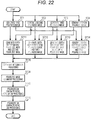
- FIG. 22 is a flowchart illustrating an operation of the fourth embodiment.
- FIGS. 23( a ) to 23( b ) are each a diagram illustrating a first example of image processing using the polarization characteristic.
- FIGS. 24( a ) to 24( b ) are each a diagram illustrating a second example of image processing using the polarization characteristic.
- FIGS. 25( a ) to 25( b ) are each a diagram illustrating a third example of image processing using the polarization characteristic.
- FIGS. 26 ( a ) to 26( c ) are each a diagram for describing calculation of an image characteristic amount.
- FIGS. 27( a ) to 27( b ) are each a diagram illustrating an operation in a case of performing matching processing.
- FIG. 28 is a diagram illustrating a functional configuration of another embodiment.
- FIGS. 29( a ) to 29( b ) are each a diagram illustrating a case of detecting an optical flow.
- FIG. 30 is a block diagram illustrating a schematic configuration of a vehicle control system.
- FIG. 31 is a diagram illustrating an example of installation of the image pickup unit.
- FIG. 1 is a diagram illustrating a functional configuration of a first embodiment of the present technology.
- An image processing apparatus 10 includes an image pickup unit 21 , a depth map generation unit 22 , an alignment unit 23 , a polarization characteristic acquisition unit 24 , and a normal map generation unit 25 .
- the image pickup unit 21 picks up a subject at a plurality of viewpoint positions through polarizing filters in different polarization directions at different viewpoint positions (for example, polarizing plates) to generate polarized images.
- the image pickup unit 21 includes a plurality of image pickup sections, for example, four image pickup sections 211 - 1 to 211 - 4 so as to acquire polarized images in three or more different polarization directions.
- a polarizing plate 210 - 1 is provided in front of the image pickup section 211 - 1 .
- polarizing plates 210 - 2 to 210 - 4 are provided in front of the image pickup sections 211 - 2 to 211 - 4 , respectively.
- the polarizing plates 210 - 1 to 210 - 4 are provided in polarization directions different from one another.
- the image pickup sections 211 - 1 to 211 - 4 generate polarized images in polarization directions different from one another.
- the image pickup unit 21 outputs image data of the polarized images generated by the image pickup sections 211 - 1 to 211 - 4 to the depth map generation unit 22 and the alignment unit 23 .
- FIGS. 2( a ) to 2( e ) are each a diagram illustrating arrangement of the image pickup sections in the image pickup unit 21 .
- the image pickup unit 21 may have a configuration in which the image pickup sections 211 - 1 to 211 - 4 are arranged at four corners of a rectangle as illustrated in (a) of FIG. 2 , and may have a configuration in which the image pickup sections 211 - 1 to 211 - 4 are arranged in a straight line as illustrated in (b) of FIG. 2 .
- the image pickup unit 21 may have a configuration in which the image pickup sections 211 - 1 to 211 - 3 are arranged at vertexes of a triangle as illustrated in (c) of FIG. 2 , and may have a configuration in which the image pickup sections 211 - 1 to 211 - 3 are arranged in a straight line as illustrated in (d) of FIG. 2 .
- the image pickup sections are arranged so as to allow the positions in the subject at which the polarization characteristic is acquired to be picked up by three or more image pickup sections.
- the image pickup unit 21 may have a configuration using a multi-lens array to generate a plurality of polarized images in different polarization directions.
- a plurality of (four in the diagram) lenses 222 are provided in a direction orthogonal to an optical axis direction in front of an image sensor 221 , and optical images of the subject are formed by respective lenses 222 on an imaging surface of the image sensor 221 .
- polarizing plates 223 are provided in front of respective lenses 222 , and the polarizing plates 223 have different polarization directions. Such a configuration allows the image sensor 221 to generate the polarized images in different polarization directions.
- the image pickup unit 21 When the image pickup unit 21 is configured in this way, it is not necessary to use special image pickup sections as in a case of generating four polarized images in different polarization directions with sub pixels in four polarization directions as one pixel, and thus the image pickup unit 21 can be made easily at low costs.
- the image pickup unit 21 uses, for example, linear polarizing plates as the polarizing filters.
- the image pickup unit 21 may use not only the linear polarizing plates but also the linear polarizing plates and circular polarizing plates made of quarter wavelength edition.
- the image pickup unit 21 may be provided with depolarizing plates between the linear polarizing plates and the image pickup sections. For example, when exposure control or the like is performed on the basis of an optical image through a half mirror in the image pickup section, reflectance and transmittance in the half mirror may vary depending on a direction of the linear polarization, which could prevent correct exposure control or the like.
- an optical image of linear polarization is converted into an unpolarized optical image and the unpolarized optical image indicating a component after linear polarization enters the image pickup section, which enables correct exposure control or the like on the basis of the optical image through the half mirror.
- the polarization directions are set so as to allow a plurality of polarized images in different polarization directions to be generated.
- the polarization direction of the linear polarizing plate is rotated by 180 degrees, components passing the linear polarizing plate become equal to each other. Accordingly, the polarization directions are set to differ from one another in a range from 0 degrees to 180 degrees.
- the image processing apparatus 10 calculates a polarization model equation on the basis of luminance and the polarization directions of the polarized images generated by the plurality of image pickup sections. Therefore, it is preferable to set the polarization directions, for example, to have identical angular differences so as to allow calculation of the polarization model equation with high precision.
- FIGS. 3( a ) to 3( b ) each illustrate the polarization directions in the image pickup unit 21 .
- (a) of FIG. 3 illustrates the polarization directions when four image pickup sections are used. In the image pickup unit 21 , for example, assuming that the polarization directions are 0 degrees, 45 degrees, 90 degrees, and 135 degrees, four image pickup sections generate four polarized images in the polarization directions having an identical angular difference (45 degrees).
- (b) of FIG. 3 illustrates the polarization directions when three image pickup sections are used. In the image pickup unit 21 , for example, assuming that the polarization directions are 0 degrees, 60 degrees, and 120 degrees, three image pickup sections generate three polarized images in the polarization directions having an identical angular difference (60 degrees).
- the depth map generation unit 22 generates a depth map indicating distance information on the subject from the images at different viewpoint positions generated by the image pickup unit 21 .
- the depth map generation unit 22 performs stereo matching processing on each pair of polarized images in the polarized images at the plurality of different viewpoint positions generated by the image pickup unit 21 .
- the depth map generation unit 22 generates, for example, the depth map indicating depth at each pixel on the basis of a stereo matching processing result and calibration information acquired in advance about the image pickup sections.
- the calibration information has positional information indicating a positional relationship between the image pickup sections.
- the depth map generation unit 22 integrates the depth map generated for each pair of polarized images to generate a depth map with higher precision than before the integration.
- the depth map generation unit 22 outputs the integrated depth map to the alignment unit 23 and the normal map generation unit 25 .
- the alignment unit 23 aligns the polarized images generated by the image pickup unit 21 on the basis of the depth map generated by the depth map generation unit 22 .
- the alignment unit 23 determines parallax on the basis of, for example, the depth of the integrated depth map generated by the depth map generation unit 22 and the positional relationship between the image pickup sections indicated in the previously acquired calibration information, and aligns the polarized images for each pixel so as to cause parallax to be “0”, that is, so as to cause the subject to match.
- the alignment unit 23 outputs the polarized images after the alignment to the polarization characteristic acquisition unit
- the polarization characteristic acquisition unit 24 acquires the polarization characteristic of the subject from a desired viewpoint position by using the polarized images after the alignment.
- the polarization characteristic acquisition unit 24 calculates a rotation matrix with the image pickup sections as the desired viewpoint position on the basis of the positional relationship between the image pickup sections indicated in the calibration information and the depth map.
- the polarization characteristic acquisition unit 24 calculates the polarization model equation indicating the polarization characteristic of the subject from the desired viewpoint position from information such as the polarization directions and luminance of the plurality of polarized images, and the rotation matrix indicating the positional relationship between the image pickup sections that generate the polarized images and the desired viewpoint position.
- the polarization characteristic acquisition unit 24 outputs the acquired polarization model equation, which is the polarization characteristic, to the normal map generation unit 25 .
- the normal map generation unit 25 generates a normal map of the subject on the basis of the polarization characteristic of the subject from the desired viewpoint position acquired by the polarization characteristic acquisition unit 24 .
- the normal map generation unit 25 calculates a zenith angle for each pixel on the basis of an azimuth angle at which luminance becomes highest and a polarization degree from the polarization characteristic acquired by the polarization characteristic acquisition unit 24 , that is, the polarization model equation, and generates the normal map that stores normal information indicating a normal direction (azimuth angle and zenith angle).
- the normal map generation unit 25 eliminates uncertainty of 180 degrees in the normal map by using the depth map that is output from the depth map generation unit 22 to the alignment unit 23 and the normal map generation unit 25 .
- FIG. 4 is a flowchart illustrating the operation of the first embodiment, and illustrates a case where the image pickup unit 21 includes four image pickup sections 211 - 1 to 211 - 4 .
- step ST 1 to step ST 4 the image pickup unit 21 generates the polarized images.
- the image pickup section 211 - 1 of the image pickup unit 21 generates a first polarized image.
- the image pickup section 211 - 2 generates a second polarized image.
- the image pickup section 211 - 3 generates a third polarized image.
- the image pickup section 211 - 4 generates a fourth polarized image.
- the image pickup sections 211 - 1 to 211 - 4 generate the polarized images in different polarization directions at different viewpoint positions, and then the image processing apparatus 10 proceeds to step ST 11 to step ST 14 .
- step ST 11 to step ST 14 the depth map generation unit 22 generates the depth maps.
- the depth map generation unit 22 generates the depth map from the first polarized image and the second polarized image.
- FIG. 5 is a flowchart illustrating an operation of the depth map generation unit.
- the depth map generation unit 22 acquires two polarized images.
- the depth map generation unit 22 acquires the first polarized image generated by the image pickup section 211 - 1 and the second polarized image generated by the image pickup section 211 - 2 , and then proceeds to step ST 102 .
- step ST 102 the depth map generation unit 22 performs edge extraction processing on each polarized image.
- the polarizing filters are provided in front of the image pickup sections and an identical subject is picked up, the images generated by the image pickup sections will be images with different luminance depending on a difference in the polarization directions. Therefore, the depth map generation unit 22 performs edge extraction processing on the polarized images to generate edge images so as to enable stereo matching processing even if luminance variation is caused by the difference in the polarization directions.
- the depth map generation unit 22 performs edge extraction processing to generate a first edge image from the first polarized image and a second edge image from the second polarized image, and then proceeds to step ST 103 .
- the depth map generation unit 22 performs stereo matching processing using the edge images.
- the depth map generation unit 22 performs stereo matching processing on the first edge image and the second edge image.
- the depth map generation unit 22 detects a pixel of interest in the first edge image and a phase difference of the second edge image corresponding to this pixel of interest (a difference in pixel positions based on parallax).
- a template matching method is used for detecting a most similar image region to a template image that is set to include the pixel of interest from the second edge image.
- the stereo matching processing is not limited to the template matching method, but other methods may be used (for example, a graph cut method or the like).
- the depth map generation unit 22 calculates the phase difference by performing the stereo matching processing, and then proceeds to step ST 105 .
- the depth map generation unit 22 performs depth map generation processing.
- the depth map generation unit 22 calculates depth, which is a distance from the pixel of interest to the subject, on the basis of information such as the phase difference detected by the stereo matching processing and the calibration information acquired in advance.
- the depth map generation unit 22 associates the calculated depth with the pixel of the polarized image to generate the depth map.
- FIG. 6 is a diagram for describing depth calculation processing. Note that FIG. 6 illustrates a case where two image pickup sections are arranged right and left in an identical posture. Here, it is assumed that, for example, the image pickup section 211 - 1 is a standard image pickup section, and that the image pickup section 211 - 2 is a reference image pickup section.
- a distance “Zp” to the subject can be calculated by Equation (1).
- FIG. 7 is a flowchart illustrating another operation of the depth map generation unit, and illustrates a case where stereo matching processing that is robust to a luminance variation is used.
- the depth map generation unit 22 captures two polarized images.
- the depth map generation unit 22 captures the first polarized image generated by the image pickup section 211 - 1 and the second polarized image generated by the image pickup section 211 - 2 , and then proceeds to step ST 104 .
- the depth map generation unit 22 performs stereo matching processing that is robust to a luminance variation.
- the depth map generation unit 22 performs stereo matching processing that is robust to a luminance variation by using the first polarized image and the second polarized image, detects the pixel of interest in the first polarized image and an amount of movement of a pixel position of the second polarized image corresponding to this pixel of interest (phase difference between parallax images).
- ZNCC zero-mean normalized cross correlation
- Equation (2) is a formula of zero-mean normalized cross correlation R ZNCC .
- Equation (2) “T (i, j)” denotes a luminance value of a pixel at coordinates (i, j) in the standard image (template), whereas “I (i, j)” denotes a luminance value of a pixel at coordinates (i, j) in the reference image.
- T (i, j) denotes a luminance value of a pixel at coordinates (i, j) in the standard image (template)
- I (i, j) denotes a luminance value of a pixel at coordinates (i, j) in the reference image.
- M is the number of pixels indicating a width of the template
- N is the number of pixels indicating a height of the template. Note that the stereo matching processing that is robust to a luminance variation is not limited to the zero-mean normalized cross correlation, but other methods may be used.
- the depth map generation unit 22 performs stereo matching processing that is robust to a luminance variation, calculates the phase difference, and proceeds to step ST 105 .
- the depth map generation unit 22 performs depth map generation processing.
- the depth map generation unit 22 calculates the depth, which is a distance from the pixel of interest to the subject, on the basis of information such as the phase difference detected by the stereo matching processing and the calibration information acquired in advance.
- the depth map generation unit 22 associates the calculated depth with the pixel of the polarized image to generate the depth map.
- step ST 12 the depth map generation unit 22 generates the depth map from the second polarized image and the third polarized image.
- the depth map generation unit 22 generates the depth map from the third polarized image and the fourth polarized image.
- step ST 14 the depth map generation unit 22 generates the depth map from the fourth polarized image and the first polarized image. Note that when the number of polarized images is “J”, the depth map generation unit 22 can generate the depth map of the maximum number of image pairs “J(J ⁇ 1)/2.”
- the pairs of polarized images are not limited to a combination illustrated in FIG. 4 .
- the depth map generation unit 22 may define any one of the polarized images as a reference and generate a plurality of depth maps for respective image pairs of this polarized image and another polarized image. For example, by defining the first polarized image as a reference, three depth maps may be generated for the first polarized image, by using the first polarized image and the second polarized image, the first polarized image and the third polarized image, and the first polarized image and the fourth polarized image.
- the depth map generation unit 22 performs depth map integration processing.
- the depth map generation unit 22 integrates the depth maps generated for respective pairs of polarized images to generate the depth map with higher precision than before the integration.
- the depth map generation unit 22 integrates the depth maps, for example, by a method similar to Japanese Patent No. 5387856 “Image processing apparatus, image processing method, image processing program, and image pickup device.” That is, the depth map generation unit 22 performs reliability determination processing on the basis of a shape of a correlation characteristic line that indicates a relationship between a correlation value indicating similarity calculated in the stereo matching processing and the pixel position. In the reliability determination, determination is made using kurtosis, which is an index indicating a degree of sharpness in the shape of the correlation characteristic line.
- the depth map generation unit 22 determines whether a difference value in the correlation value between a vertex and a surrounding point in the correlation characteristic line, or determination may be made using an integrated value (integration value) of a differential value of the correlation value at each pixel position, and the like. Furthermore, the depth map generation unit 22 generates the depth map after the integration on the basis of a reliability determination result in each depth map by performing processing for employing the depth with the highest reliability at a pixel indicating an identical position of the subject for each pixel. Note that when a plurality of depth maps are generated on the basis of any one of the polarized images, in each depth map, an identical pixel position indicates an identical position of the subject. Therefore, by employing the most reliable depth from reliability of each depth map at each pixel position, the depth maps can be easily integrated. The depth map generation unit 22 performs the depth map integration processing, generates the depth map after the integration, and then proceeds to step ST 30 .
- the alignment unit 23 performs polarized image alignment processing.
- the alignment unit 23 determines parallax with respect to the desired viewpoint position on the basis of the depth map after metaphor integration and the positional information between the image pickup sections indicated in the calibration information, and then aligns the plurality of polarized images so as to cause parallax to be “0”, that is, so as to cause the subject to match.
- the desired viewpoint position is not limited to any one of the image pickup sections 211 - 1 to 211 - 4 , but may be, for example, a position within a rectangle or the like when the image pickup sections 211 - 1 to 211 - 4 are provided at four corners of the rectangle.
- the alignment unit 23 aligns the polarized images, and then proceeds to step ST 40 .
- step ST 40 the polarization characteristic acquisition unit 24 performs polarization characteristic acquisition processing.
- the polarization characteristic acquisition unit 24 acquires the polarization characteristic at the desired viewpoint position by using the polarized image after alignment.
- FIG. 8 is a flowchart illustrating polarization characteristic acquisition processing.
- step ST 401 the polarization characteristic acquisition unit 24 acquires the positional information between the image pickup sections.
- the polarization characteristic acquisition unit 24 acquires the positional information between the image pickup sections included in the calibration information that is set in advance.
- step ST 402 the polarization characteristic acquisition unit 24 acquires the polarized images after alignment.
- the polarization characteristic acquisition unit 24 acquires the polarized images after alignment that is output from the alignment unit 23 .
- step ST 403 the polarization characteristic acquisition unit 24 acquires the depth map.
- the polarization characteristic acquisition unit 24 acquires the depth map generated by the depth map generation unit 22 .
- step ST 404 the polarization characteristic acquisition unit 24 calculates the rotation matrix to the desired viewpoint position.
- the polarization characteristic acquisition unit 24 calculates the rotation matrix R with the image pickup section that generates the polarized image as the viewpoint position desired by a user or the like on the basis of the calibration information and the depth map, and then proceeds to step ST 405 .
- Equation (3) illustrates the rotation matrix R.
- step ST 405 the polarization characteristic acquisition unit 24 calculates the polarization model equation with respect to the desired viewpoint position.
- the image pickup section 211 - p at the desired viewpoint position has the positional relationship illustrated in FIG. 9 .
- FIG. 10 is a diagram for describing a subject surface shape and the polarized image.
- the subject OB is illuminated using a light source LT, and the image pickup section 211 - n picks up the subject OB through a polarizing plate 210 - n .
- luminance of the subject OB varies depending on the polarization direction of the polarizing plate 210 - n in the picked up image, and that the highest luminance is Imax and the lowest luminance is Imin.
- an x-axis and a y-axis in two-dimensional coordinates are on a plane of the polarizing plate 210 - n , and that the polarization direction of the polarizing plate 210 - n is a polarization angle v, which is an angle of a y-axis direction with respect to the x-axis.
- the polarizing plate 210 - n has a cycle of 180 degrees, and when the polarization direction is rotated by 180 degrees, the polarizing plate 210 - n returns to an original polarization state.
- the polarization angle ⁇ when the highest luminance Imax is observed is an azimuth angle ⁇ .
- FIG. 11 illustrates a relationship between luminance and the polarization angle.
- Equation (4) the polarization angle ⁇ is apparent at a time of generation of the polarized image, and the highest luminance Imax, the lowest luminance Imin, and the azimuth angle ⁇ are variables.
- an object surface normal is expressed by a polar coordinate system, and that normal information is the azimuth angle ⁇ and a zenith angle ⁇ .
- the zenith angle ⁇ is an angle from a z-axis to the normal
- the azimuth angle ⁇ is an angle of the y-axis direction with respect to the x-axis as described above.
- a polarization degree ⁇ can be calculated by Equation (5).
- the polarization degree ⁇ can be calculated using a relative refractive index n of the subject OB and the zenith angle ⁇ , as expressed by Equation (5).
- a relationship between the polarization degree and the zenith angle is, for example, a characteristic illustrated in FIG. 12 , and by using this characteristic, the zenith angle ⁇ is determined on the basis of the polarization degree ⁇ . Note that as is apparent from Equation (5), the characteristic illustrated in FIG. 12 is dependent on the relative refractive index n, and the polarization degree increases as the relative refractive index n increases.
- I ′ I max ′ + I min ′ 2 + I max ′ - I min ′ 2 ⁇ cos ⁇ ⁇ 2 ⁇ ( v - ⁇ ′ ) ( 6 )
- the normal of the image pickup section 211 - n is the direction of the azimuth angle ⁇ and the zenith angle ⁇ , and the normal N detected by the image pickup section 211 - n can be expressed by Equation (12).
- a normal N′ detected by the image pickup section 211 - p can be expressed by Equation (13) by using the rotation matrix R expressed by Equation (3), and thus the relationship of Equation (14) holds.
- an azimuth angle ⁇ ′ can be calculated by Equation (15) from components of the rotation matrix R, the zenith angle ⁇ , and the azimuth angle ⁇ .
- a zenith angle ⁇ ′ can be calculated by Equation (16) from the components of the rotation matrix R, the zenith angle ⁇ , and the azimuth angle ⁇ .
- Equation (17) the polarization model equation (8) indicating the polarization characteristic of the image pickup section 211 - p is expressed by Equation (17) as a function using three variables, a luminance additional value A, the zenith angle ⁇ , and the azimuth angle ⁇ .
- Similar modeling is performed about three or more image pickup sections, and by using the rotation matrix based on luminance of the polarized images obtained by picking up the subject at three or more viewpoint positions through the polarizing filters in different polarization directions at different viewpoint positions and the calibration information (positional information between the image pickup sections), the luminance additional value A, the azimuth angle ⁇ , and the zenith angle ⁇ are calculated, which are three variables.
- the polarization model equation indicating the polarization characteristic at the desired viewpoint position can be calculated.
- the luminance additional value A, the azimuth angle ⁇ , and the zenith angle ⁇ which are three variables, are analytically calculated from luminance and the polarization model equation (polarization model equation using the rotation matrix between the image pickup sections based on the calibration information) about three or more image pickup sections.
- the three variables may be calculated so as to minimize an error by using an optimization technique, for example, the LM method and the steepest descent method.
- the three variables may be approximately calculated assuming that spacing between the image pickup sections is small compared with the depth and the rotation matrix can be ignored.
- the polarization characteristic acquisition unit 24 performs the above-described processing, and calculates the polarization model equation for the desired viewpoint position, that is, the polarization model equation for the image pickup section 211 - p , which is the polarization characteristic.
- step ST 50 the normal map generation unit 25 performs normal map generation processing.
- FIG. 13 is a flowchart illustrating the normal map generation processing.
- the normal map generation unit 25 calculates the normal.
- the normal map generation unit 25 determines the azimuth angle ⁇ ′ at which luminance becomes highest by using the polarization model equation indicating the polarization characteristic at the desired viewpoint position, that is, Equation (17). Note that a polarization degree ⁇ ′ may be calculated by Equation (11).
- the normal map generation unit 25 calculates the zenith angle ⁇ ′ for each pixel on the basis of the azimuth angle ⁇ ′ and the polarization degree ⁇ ′ at which luminance becomes highest, calculates the normal information on the subject (information indicating the azimuth angle ⁇ ′ and the zenith angle ⁇ ′), and then proceeds to step ST 502 .
- step ST 502 the normal map generation unit 25 eliminates the uncertainty of 180 degrees.
- FIGS. 14( a ) to 14 ( c ) are each a diagram for describing elimination of the uncertainty of 180 degrees.
- the image pickup section 211 picks up the subject OB.
- the polarizing plate will return to an original polarization state, and for example, as illustrated in (b) of FIG. 14 , in an upper half region GA of the subject OB, a normal direction (indicated by arrows) is a right direction.
- the normal map generation unit 25 determines a gradient direction of the subject OB on the basis of the depth map, the normal map generation unit 25 can determine that the subject OB is a shape projecting in a direction of the image pickup section.
- the normal map generation unit 25 can determine that the normal direction of the lower half region GB illustrated in (b) of FIG. 14 is an opposite direction. Accordingly, by reversing the normal direction of the lower half region GB, the normal map generation unit 25 eliminates the uncertainty of 180 degrees, as illustrated in (c) of FIG. 14 .
- the normal map generation unit 25 eliminates the uncertainty of 180 degrees from the normal calculated in step ST 501 on the basis of the depth map, and generates the normal map that correctly indicates the surface shape of the subject.
- the image processing apparatus not only performs the above-described processing in order of steps, but also may perform, for example, processing such as acquisition of images and information, and generation of the depth map by parallel processing.
- performing the above-described processing by pipeline processing makes it possible to calculate the polarization characteristic at the desired viewpoint position and to generate the normal map, for example, sequentially for each frame
- the first embodiment allows acquisition of the polarization characteristic for each pixel at the desired viewpoint position without causing reduction in temporal resolution and spatial resolution.
- the first embodiment allows generation of the normal information on the subject from the polarization characteristic at the desired viewpoint position.
- the first embodiment allows acquisition of the polarization characteristic with high precision, because the polarization characteristic is acquired by integrating the depth map generated through combination and use of the polarized images in different polarization directions at different viewpoint positions and using the polarized images aligned using the integrated depth map.
- the first embodiment allows generation of the normal map on the basis of the polarization characteristic at the desired viewpoint position, thereby allowing generation of the normal map according to the desired viewpoint position. Since this normal map corresponds to the characteristic amount according to the subject surface shape, it becomes possible to perform processing such as subject recognition and subject matching processing with high precision by using this normal map.
- the depth map is generated by using the polarized images, it is not necessary to provide image pickup sections to be used only for generation of the depth map.
- the second embodiment describes a case of generating a depth map with high spatial resolution by using a generated normal map.
- FIG. 15 is a diagram illustrating a functional configuration of the second embodiment of the present technology.
- an image processing apparatus 10 includes an image pickup unit 21 , a depth map generation unit 22 , an alignment unit 23 , a polarization characteristic acquisition unit 24 , and a normal map generation unit 25 .
- the image processing apparatus 10 of the second embodiment includes a high-precision depth map generation unit 26 .
- the image pickup unit 21 picks up a subject at a plurality of viewpoint positions through polarizing filters in different polarization directions at different viewpoint positions (for example, polarizing plates) and generates polarized images.
- the image pickup unit 21 includes a plurality of image pickup sections, for example, four image pickup sections 211 - 1 to 211 - 4 so as to generate polarized images in three or more different polarization directions.
- a polarizing plate 210 - 1 is provided in front of the image pickup section 211 - 1 .
- polarizing plates 210 - 2 to 210 - 4 are provided in front of the image pickup sections 211 - 2 to 211 - 4 , respectively.
- the polarizing plates 210 - 1 to 210 - 4 are provided in polarization directions different from one another.
- the image pickup sections 211 - 1 to 211 - 4 generate polarized images in the polarization directions different from one another.
- the image pickup unit 21 outputs image data of the polarized images generated by the image pickup sections 211 - 1 to 211 - 4 to the depth map generation unit 22 and the alignment unit 23 .
- the image pickup unit 21 uses, for example, linear polarizing plates or the like as the polarizing filters. Note that the image pickup unit 21 may generate polarized images in three or more different polarization directions with another configuration in a similar manner to the above-described first embodiment.
- the depth map generation unit 22 generates a depth map indicating distance information on the subject from the polarized images at different viewpoint positions generated by the image pickup unit 21 .
- the depth map generation unit 22 performs stereo matching processing by using the polarized images at different viewpoint positions to generate the depth map indicating depth at each pixel.
- the depth map generation unit 22 generates the depth map for each pair of polarized images at different viewpoint positions and integrates the generated depth map to generate the depth map with higher precision than before integration.
- the depth map generation unit 22 outputs the depth map after integration to the alignment unit 23 and the normal map generation unit 25 .
- the alignment unit 23 aligns the polarized images generated by the image pickup unit 21 on the basis of the depth map generated by the depth map generation unit 22 .
- the alignment unit 23 determines parallax between the polarized images on the basis of the depth in the depth map generated by the depth map generation unit 22 and a positional relationship of the image pickup sections indicated in the calibration information acquired in advance, and aligns the polarized images at each pixel.
- the alignment unit 23 outputs the polarized images after alignment to the polarization characteristic acquisition unit 24 .
- the polarization characteristic acquisition unit 24 acquires the polarization characteristic of the subject from a desired viewpoint position by using the polarized images after alignment.
- the polarization characteristic acquisition unit 24 calculates a rotation matrix with the image pickup sections as the desired viewpoint position on the basis of the positional relationship of the image pickup sections indicated in the calibration information and the depth map.
- the polarization characteristic acquisition unit 24 calculates a polarization model equation indicating the polarization characteristic of the subject from the desired viewpoint position from information such as the polarization directions and luminance of the plurality of polarized images, and the rotation matrix indicating the positional relationship between the image pickup sections that generate the polarized images and the desired viewpoint position.
- the polarization characteristic acquisition unit 24 outputs the acquired polarization model equation, which is the polarization characteristic, to the normal map generation unit 25 .
- the normal map generation unit 25 generates the normal map of the subject on the basis of the polarization characteristic of the subject from the desired viewpoint position acquired by the polarization characteristic acquisition unit 24 .
- the normal map generation unit 25 calculates a zenith angle at each pixel on the basis of an azimuth angle at which luminance becomes highest and a polarization degree from the polarization model equation acquired by the polarization characteristic acquisition unit 24 , and generates the normal map that stores normal information indicating a normal direction (azimuth angle and zenith angle). Furthermore, the normal map generation unit 25 eliminates uncertainty of 180 degrees in the normal map by using the depth map, and outputs the normal map from which uncertainty of 180 degrees is eliminated to the high-precision depth map generation unit 26 .
- the high-precision depth map generation unit 26 performs precision-enhancing processing of the depth map by using the normal map.
- the high-precision depth map generation unit 26 traces a subject surface shape starting from a pixel at which depth is obtained on the basis of the subject surface shape indicated in the normal map generated by the normal map generation unit 25 and depth indicated in the depth map that is output from the depth map generation unit 22 .
- the subject surface shape is traced starting from the pixel at which depth is obtained, and the normal map generation unit 25 estimates depth corresponding to the pixel at which depth is not obtained.
- the high-precision depth map generation unit 26 generates the depth map that is higher in spatial resolution than the depth map that is output from the depth map generation unit 22 .
- FIG. 16 is a flowchart illustrating the operation of the second embodiment.
- the image pickup unit 21 in a similar manner to the first embodiment, in step ST 1 to step ST 4 , the image pickup unit 21 generates the polarized images.
- the image pickup section 211 - 1 of the image pickup unit 21 generates a first polarized image.
- the image pickup section 211 - 2 generates a second polarized image.
- the image pickup section 211 - 3 generates a third polarized image.
- the image pickup section 211 - 4 generates a fourth polarized image.
- the image pickup sections 211 - 1 to 211 - 4 generate the polarized images in different polarization directions at different viewpoint positions, and then the image processing apparatus 10 proceeds to step ST 11 to step ST 14 .
- step ST 11 to step ST 14 the depth map generation unit 22 generates the depth maps.
- the depth map generation unit 22 generates the depth map from two polarized images at different viewpoint positions, and then proceeds to step ST 20 . Note that pairs of polarized images are not limited to a combination illustrated in FIG. 16 .
- step ST 20 the depth map generation unit 22 performs depth map integration processing.
- the depth map generation unit 22 integrates the depth maps generated in step ST 11 to step ST 14 , and then proceeds to step ST 30 .
- step ST 30 the alignment unit 23 performs polarized image alignment processing.
- the alignment unit 23 aligns the polarized images by using the depth map after integration, and then proceeds to step ST 40 .
- step ST 40 the polarization characteristic acquisition unit 24 performs polarization characteristic acquisition processing.
- the polarization characteristic acquisition unit 24 calculates the polarization model equation for the desired viewpoint position by using the polarized images after alignment, and then proceeds to step ST 50 .
- step ST 50 the normal map generation unit 25 performs normal map generation processing.
- the normal map generation unit 25 generates the normal map indicating a surface normal of the subject at each pixel on the basis of the polarization characteristic at the desired viewpoint position, and then proceeds to step ST 60 .
- step ST 60 the high-precision depth map generation unit 26 performs high-precision depth map generation processing.
- the high-precision depth map generation unit 26 generates the depth map with high spatial resolution from the depth map generated in step ST 20 and the normal map generated in step ST 50 .
- FIGS. 17 ( a ) to 17 ( d ) are each a diagram for describing the high-precision depth map generation processing. Note that for simple description, for example, processing about one line will be described. As illustrated in (a) of FIG. 17 , it is assumed that the image pickup section 211 picks up the subject OB, that the depth map illustrated in (b) of FIG. 17 is obtained by the depth map generation unit 22 , and that the normal map illustrated in (c) of FIG. 17 is obtained by the normal map generation unit 25 .
- the high-precision depth map generation unit 26 estimates the surface shape of the subject OB on the basis of the normal map.
- a second pixel from the left end corresponds to an inclined surface approaching in a direction of the image pickup unit 21 from the subject surface corresponding to the left end pixel on the basis of the normal direction of this pixel. Therefore, the high-precision depth map generation unit 26 estimates depth of the second pixel from the left end at, for example, “1.5 (meters)”, by tracing the surface shape of the subject OB starting from the left end pixel.
- the high-precision depth map generation unit 26 stores the estimated depth in the depth map. It can be determined that a third pixel from the left end corresponds to a surface facing the image pickup unit 21 on the basis of the normal direction of this pixel. Therefore, the high-precision depth map generation unit 26 estimates depth of the third pixel from the left end at, for example, “1 (meter)”, by tracing the surface shape of the subject OB starting from the left end pixel. In addition, the high-precision depth map generation unit 26 stores the estimated depth in the depth map. It can be determined that a fourth pixel from the left end corresponds to an inclined surface in a direction away from the image pickup unit 21 from the subject surface corresponding to the third pixel from the left end.
- the high-precision depth map generation unit 26 estimates depth of the fourth pixel from the left end pixel at, for example, “1.5 (meters)”, by tracing the surface shape of the subject OB starting from the left end pixel. In addition, the high-precision depth map generation unit 26 stores the estimated depth in the depth map. Similarly, depth of a fifth pixel from the left end is estimated at, for example, “2 (meters)” and is stored in the depth map.
- the high-precision depth map generation unit 26 performs precision-enhancing processing of the depth map by using the depth map and the normal map, and traces the surface shape starting from the depth included in the depth map on the basis of the normal map, thereby estimating the depth. Therefore, even if some depth is missing in the depth map illustrated in (b) of FIG. 17 generated by the depth map generation unit 22 , the high-precision depth map generation unit 26 can compensate for the missing depth. Accordingly, the depth map illustrated in (d) of FIG. 17 , which has a spatial resolution equal to or higher than the depth map illustrated in (b) of FIG. 17 , can be generated.
- the second embodiment not only an operational effect of the first embodiment can be obtained, but also even in a subject region where it is difficult to obtain depth by the stereo matching processing, it is possible to estimate depth by using the normal map generated on the basis of the plurality of polarized images. Therefore, it is possible to generate the depth map having a spatial resolution equal to or higher than the depth map generated by the depth map generation unit 22 .
- the depth map is generated without being affected by a luminance difference of polarized images.
- FIG. 18 is a diagram illustrating a functional configuration of the third embodiment.
- An image processing apparatus 10 includes an image pickup unit 21 a , a depth map generation unit 22 a , and in a similar manner to the first embodiment, an alignment unit 23 , a polarization characteristic acquisition unit 24 , and a normal map generation unit 25 .
- the image pickup unit 21 a picks up a subject at a plurality of viewpoint positions through polarizing filters in different polarization directions at different viewpoint positions (polarizing plates) and generates polarized images.
- the image pickup unit 21 a includes a plurality of image pickup sections, for example, four image pickup sections 211 - 1 to 211 - 4 so as to generate polarized images in three or more different polarization directions.
- a polarizing plate 210 - 1 is provided in front of the image pickup section 211 - 1 .
- polarizing plates 210 - 2 to 210 - 4 are provided in front of the image pickup sections 211 - 2 to 211 - 4 , respectively.
- the polarizing plates 210 - 1 to 210 - 4 are provided in polarization directions different from one another.
- the image pickup sections 211 - 1 to 211 - 4 generate polarized images in the polarization directions different from one another.
- the image pickup unit 21 a outputs image data of the polarized images generated by the image pickup sections 211 - 1 to 211 - 4 to the alignment unit 23 .
- the image pickup unit 21 a uses, for example, linear polarizing plates or the like as the polarizing filters. Note that the image pickup unit 21 a may generate polarized images in three or more different polarization directions with another configuration in a similar manner to the above-described first embodiment.
- the image pickup unit 21 a includes image pickup sections that perform image pickup without through polarizing filters or through polarizing filters in an identical polarization direction.
- FIG. 18 illustrates a configuration including image pickup sections 211 - 5 and 211 - 6 that perform image pickup without through polarizing filters. Polarizing filters are not provided in front of the image pickup sections 211 - 5 and 211 - 6 , and the image pickup sections 211 - 5 and 211 - 6 generate unpolarized images.
- the image pickup unit 21 a outputs the unpolarized images generated by the image pickup sections 211 - 5 and 211 - 6 to the depth map generation unit 22 a.
- FIGS. 19( a ) to 19( e ) are each a diagram illustrating arrangement of the image pickup sections in the image pickup unit 21 a .
- the image pickup unit 21 a has a configuration in which the image pickup sections 211 - 1 to 211 - 4 are arranged at four corners of a rectangle as illustrated in (a) of FIG. 19 , and the image pickup section 211 - 5 is arranged on a left side of the image pickup sections 211 - 1 to 211 - 4 that are arranged in a rectangle, and the image pickup section 211 - 6 is arranged on a right side.
- FIGS. 19( a ) to 19( e ) illustrate that the image pickup sections without arrows indicating polarization directions are the image pickup sections that generate unpolarized images.
- the image pickup unit 21 a may have a configuration in which the image pickup sections that generate polarized images are arranged in a straight line as illustrated in (b) and (c) of FIG. 19 , and the image pickup sections that generate unpolarized images are arranged on the left side and right side of the image pickup sections arranged in a straight line.
- the image pickup unit 21 a may have a configuration in which more image pickup sections are provided that generate unpolarized images, depth maps generated for each pair of the unpolarized images are integrated, and a higher-precision depth map can be generated.
- a configuration is used in which, as illustrated in (d) of FIG. 19 , two image pickup sections that generate unpolarized images are provided in a vertical direction on the right and left of the image pickup sections that are arranged in a rectangle and generate polarized images, and a plurality of depth maps generated for each pair of the unpolarized images can be integrated to generate a high-precision depth map.
- a configuration may be used in which, as illustrated in (e) of FIG.
- image pickup sections that generate unpolarized images are provided so as to surround image pickup sections that are arranged in a rectangle and generate polarized images, and a plurality of depth maps generated for each pair of the unpolarized images can be integrated to generate a high-precision depth map.
- the image pickup sections that generate unpolarized images may be arranged in any manner without limitation to the arrangement illustrated in (d) and (e) of FIG. 19 as long as the plurality of depth maps can be integrated to generate a high-precision depth map.
- the depth map generation unit 22 a generates the depth map indicating distance information on the subject from the unpolarized images generated by the image pickup unit 21 a .
- the depth map generation unit 22 a performs stereo matching processing by using the unpolarized images at different viewpoint positions and generates the depth map indicating depth at each pixel.
- the depth map generation unit 22 a outputs the generated depth map to the alignment unit 23 and the normal map generation unit 25 .
- the depth map generation unit 22 a may generate the depth maps for respective pairs, perform depth map integration processing as described above, thereby generating the high-precision depth map.
- the alignment unit 23 aligns the polarized images generated by the image pickup unit 21 a on the basis of the depth map generated by the depth map generation unit 22 a .
- the alignment unit 23 determines parallax between the polarized images and aligns the polarized images at each pixel on the basis of depth in the depth map generated by the depth map generation unit 22 a and a positional relationship of the image pickup sections indicated using calibration information acquired in advance.
- the alignment unit 23 outputs the polarized images after alignment to the polarization characteristic acquisition unit 24 .
- the polarization characteristic acquisition unit 24 acquires the polarization characteristic of the subject from a desired viewpoint position by using the polarized images after alignment.
- the polarization characteristic acquisition unit 24 calculates a rotation matrix with the image pickup sections as the desired viewpoint position on the basis of the positional relationship of the image pickup sections indicated using the calibration information and the depth map.
- the polarization characteristic acquisition unit 24 calculates a polarization model equation indicating the polarization characteristic of the subject from the desired viewpoint position from information such as the polarization directions and luminance of the plurality of polarized images and the rotation matrix indicating the positional relationship between the image pickup sections that generate these polarized images and the desired viewpoint position.
- the polarization characteristic acquisition unit 24 outputs the acquired polarization model equation, which is the polarization characteristic, to the normal map generation unit 25 .
- the normal map generation unit 25 generates a normal map of the subject on the basis of the polarization characteristic of the subject from the desired viewpoint position acquired by the polarization characteristic acquisition unit 24 .
- the normal map generation unit 25 calculates a zenith angle for each pixel on the basis of an azimuth angle at which luminance becomes highest and a polarization degree from the polarization model equation acquired by the polarization characteristic acquisition unit 24 , and generates the normal map that stores normal information indicating a normal direction (azimuth angle and zenith angle). Furthermore, the normal map generation unit 25 eliminates uncertainty of 180 degrees in the normal map by using the depth map, and generates the normal map from which the uncertainty of 180 degrees is eliminated.
- FIG. 20 is a flowchart illustrating the operation of the third embodiment.
- the image pickup unit 21 a generates the polarized images.
- the image pickup section 211 - 1 of the image pickup unit 21 a generates a first polarized image.
- the image pickup section 211 - 2 generates a second polarized image.
- the image pickup section 211 - 3 generates a third polarized image.
- the image pickup section 211 - 4 generates a fourth polarized image.
- step ST 5 to step ST 6 the image pickup unit 21 a generates the unpolarized images without through the polarizing filters.
- the image pickup section 211 - 5 of the image pickup unit 21 a generates a first unpolarized image.
- step ST 6 the image pickup section 211 - 6 generates a second unpolarized image.
- the image pickup sections 211 - 1 to 211 - 6 generate the plurality of polarized images in different polarization directions at different viewpoint positions and the unpolarized images at different viewpoint positions, and then the image processing apparatus 10 proceeds to step ST 15 .
- step ST 15 the depth map generation unit 22 a generates the depth map.
- the depth map generation unit 22 a performs stereo matching processing by using the first unpolarized image and the second unpolarized image at different viewpoint positions, generates the depth map, and then proceeds to step ST 30 .
- step ST 30 the alignment unit 23 performs polarized image alignment processing.
- the alignment unit 23 aligns respective polarized images by using the depth map generated in step ST 15 , and then proceeds to step ST 40 .
- step ST 40 the polarization characteristic acquisition unit 24 performs polarization characteristic acquisition processing.
- the polarization characteristic acquisition unit 24 calculates the polarization model equation for the desired viewpoint position by using the polarized images after alignment, and then proceeds to step ST 50 .
- step ST 50 the normal map generation unit 25 performs normal map generation processing.
- the normal map generation unit 25 generates the normal map indicating a surface normal of the subject for each pixel on the basis of the polarization characteristic at the desired viewpoint position.
- the depth map since the depth map is generated using the unpolarized images, the depth map can be easily generated with high precision compared with a case where the polarized images are used that can produce a difference in luminance depending on the polarization direction.
- the polarization characteristic at the desired viewpoint position can be acquired for each pixel with high precision, without causing reduction in temporal resolution and spatial resolution.
- the fourth embodiment describes a case of performing processing using an acquired polarization characteristic at a desired viewpoint position.
- FIG. 21 is a diagram illustrating a functional configuration of the fourth embodiment.
- an image processing apparatus 10 includes an image pickup unit 21 , a depth map generation unit 22 , an alignment unit 23 , and a polarization characteristic acquisition unit 24 .
- the image processing apparatus 10 of the fourth embodiment includes a polarization characteristic use unit 27 .
- the image pickup unit 21 picks up a subject at a plurality of viewpoint positions through polarizing filters in different polarization directions at different viewpoint positions (for example, polarizing plates) and generates polarized images.
- the image pickup unit 21 includes a plurality of image pickup sections, for example, four image pickup sections 211 - 1 to 211 - 4 so as to generate polarized images in three or more different polarization directions.
- a polarizing plate 210 - 1 is provided in front of the image pickup section 211 - 1 .
- polarizing plates 210 - 2 to 210 - 4 are provided in front of the image pickup sections 211 - 2 to 211 - 4 , respectively.
- the polarizing plates 210 - 1 to 210 - 4 are provided in polarization directions different from one another.
- the image pickup sections 211 - 1 to 211 - 4 generate polarized images in the polarization directions different from one another.
- the image pickup unit 21 outputs image data of the polarized images generated by the image pickup sections 211 - 1 to 211 - 4 to the depth map generation unit 22 and the alignment unit 23 .
- the image pickup unit 21 uses, for example, linear polarizing plates or the like as the polarizing filters. Note that the image pickup unit 21 may generate polarized images in three or more different polarization directions with another configuration in a similar manner to the above-described first embodiment.
- the depth map generation unit 22 generates a depth map indicating distance information on the subject from the polarized images at different viewpoint positions generated by the image pickup unit 21 .
- the depth map generation unit 22 performs stereo matching processing by using the polarized images at different viewpoint positions to generate the depth map indicating depth at each pixel.
- the depth map generation unit 22 generates the depth map for each pair of polarized images at different viewpoint positions and integrates the generated depth map to generate the depth map with higher precision than before integration.
- the depth map generation unit 22 outputs the depth map after integration to the alignment unit 23 and a normal map generation unit 25 .
- the alignment unit 23 aligns the polarized images generated by the image pickup unit 21 on the basis of the depth map generated by the depth map generation unit 22 .
- the alignment unit 23 determines parallax between the polarized images on the basis of the depth in the depth map generated by the depth map generation unit 22 and a positional relationship of the image pickup sections indicated in the calibration information acquired in advance, and aligns the polarized images at each pixel.
- the alignment unit 23 outputs the polarized images after alignment to the polarization characteristic acquisition unit 24 .
- the polarization characteristic acquisition unit 24 acquires the polarization characteristic of the subject from a desired viewpoint position by using the polarized images after alignment.
- the polarization characteristic acquisition unit 24 calculates a rotation matrix with the image pickup sections as the desired viewpoint position on the basis of the positional relationship of the image pickup sections indicated in the calibration information and the depth map.
- the polarization characteristic acquisition unit 24 calculates a polarization model equation indicating the polarization characteristic of the subject from the desired viewpoint position from information such as the polarization directions and luminance of the plurality of polarized images, and the rotation matrix indicating the positional relationship between the image pickup sections that generate the polarized images and the desired viewpoint position.
- the polarization characteristic acquisition unit 24 outputs the acquired polarization model equation, which is the polarization characteristic, to the polarization characteristic use unit
- the polarization characteristic use unit 27 uses the polarization characteristic acquired by the polarization characteristic acquisition unit 24 to perform modification processing on images generated by the image pickup unit 21 , such as adjustment of a reflection component of an image at the desired viewpoint position, for example. Specifically, modification processing are performed such as processing for generating a polarized image of an arbitrary azimuth angle, processing for eliminating the reflection component, and processing for adjusting a specular reflection component and adjusting glossiness.
- the polarization characteristic use unit 27 may use the polarization characteristic according to a surface shape of the subject as an image characteristic amount to perform processing such as processing in consideration of the surface shape of the subject and recognition of a three-dimensional subject.
- FIG. 22 is a flowchart illustrating the operation of the fourth embodiment.
- the image pickup unit 21 in a similar manner to the first embodiment, in step ST 1 to step ST 4 , the image pickup unit 21 generates the polarized images.
- the image pickup section 211 - 1 of the image pickup unit 21 generates a first polarized image.
- the image pickup section 211 - 2 generates a second polarized image.
- the image pickup section 211 - 3 generates a third polarized image.
- the image pickup section 211 - 4 generates a fourth polarized image.
- the image pickup sections 211 - 1 to 211 - 4 generate the polarized images in different polarization directions at different viewpoint positions, and then the image processing apparatus 10 proceeds to step ST 11 to step ST 14 , respectively.
- step ST 11 to step ST 14 the depth map generation unit 22 generates the depth maps.
- the depth map generation unit 22 generates the depth map from two polarized images at different viewpoint positions, and then proceeds to step ST 20 . Note that pairs of polarized images are not limited to a combination illustrated in FIG. 22 .
- step ST 20 the depth map generation unit 22 performs depth map integration processing.
- the depth map generation unit 22 integrates the depth maps generated in step ST 11 to step ST 14 , and then proceeds to step ST 30 .
- step ST 30 the alignment unit 23 performs polarized image alignment processing.
- the alignment unit 23 aligns the polarized images by using the depth map after integration, and then proceeds to step ST 40 .
- step ST 40 the polarization characteristic acquisition unit 24 performs polarization characteristic acquisition processing.
- the polarization characteristic acquisition unit 24 calculates the polarization model equation for the desired viewpoint position by using the polarized images after alignment, and then proceeds to step ST 70 .
- the polarization characteristic use unit 27 performs polarization characteristic use processing.
- the polarization characteristic use unit 27 uses the acquired polarization characteristic, for example, to perform image modification processing.
- FIGS. 23( a ) to 23( b ) , FIGS. 24( a ) to 24( b ) , and FIGS. 25( a ) to 25( b ) each illustrate a case of adjusting the reflection component of the image as modification processing using the polarization characteristic.
- (a) of FIG. 23 , (a) of FIG. 24 , and (a) of FIG. 25 each illustrate a relationship between an azimuth angle and luminance on the basis of the polarization model equation calculated in step ST 40 .
- a range up to the lowest luminance Imin is a component in which luminance does not vary regardless of a polarization state
- a luminance range from the lowest luminance Imin to the highest luminance Imax is a range in which luminance varies depending on the polarization state. Therefore, controlling luminance according to the azimuth angle makes it possible to obtain a filter effect corresponding to a PL filter in a pseudo manner, and as illustrated in (b) of FIG. 23 , a polarized image through a polarizing filter in a desired polarization direction can be generated from a normal picked up image.
- the range up to the lowest luminance Imin is a component in which luminance does not vary regardless of the polarization state and corresponds to an unpolarized component
- the luminance range from the lowest luminance Imin to the highest luminance Imax is a range in which luminance varies depending on the polarization state, and corresponds to a polarized component. Accordingly, as illustrated in (b) of FIG. 24 , by eliminating a luminance component corresponding to the polarized component from the normal picked up image, a picked up image from which the reflection component is eliminated can be generated.
- the range up to the lowest luminance Imin is a component in which luminance does not vary regardless of the polarization state and corresponds to the unpolarized component, and this range can be mostly regarded as a diffused reflection component.
- the luminance range from the lowest luminance Imin to the highest luminance Imax can be mostly regarded as a specular reflection component. Therefore, as illustrated in (b) of FIG. 25 , by suppressing the specular reflection component, it is possible to generate a picked up image in which glossiness is suppressed. Alternatively, by emphasizing the specular reflection component, it is possible to generate a picked up image with enhanced glossiness.
- the polarization characteristic use unit 27 may calculate the image characteristic amount by using the polarization characteristic calculated by the polarization characteristic acquisition unit, and may perform processing in consideration of the surface shape of the subject by using the image characteristic amount, such as matching processing of three-dimensional subjects and recognition processing of the three-dimensional subject, for example. Next, as processing in consideration of the surface shape of the subject, an operation of performing matching processing of the three-dimensional subject will be described.
- the polarization characteristic use unit 27 uses the polarization characteristic, for example, to calculate the image characteristic amount according to the surface shape of the subject in the polarized image at each pixel.
- FIGS. 26( a ) to 26( c ) are each a diagram for describing calculation of the image characteristic amount.
- (a) and (b) of FIG. 26 each illustrate a relationship between an angle of the polarization direction and luminance in a characteristic amount calculation object pixel of the image characteristic amount in the polarized image (hereinafter simply referred to as “object pixel”).
- object pixel a characteristic amount calculation object pixel of the image characteristic amount in the polarized image
- FIG. 26 illustrates a case where, for example, illumination light is brighter than (a) of FIG. 26 . Note that FIGS.
- 26( a ) to 26( c ) each illustrate a case where the polarization angle is 0 degrees, 45 degrees, 90 degrees, and 135 degrees.
- luminance when the polarization angle at the object pixel is 0 degrees is I 0° and I′ 0°
- luminance when the polarization angle is 45 degrees is I 45° and I′ 45°
- luminance when the polarization angle is 90 degrees is I 90° and I′ 90°
- luminance when the polarization angle is 135 degrees is I 135° and I′ 135° .
- luminance of the polarized image varies depending on illumination or the like.
- the polarization characteristic use unit 27 normalizes luminance so as to make it possible to determine whether the polarization characteristic has an identical characteristic even when luminance is different.
- the polarization characteristic use unit 27 calculates an average of luminance at each polarization angle, divides the luminance at each polarization angle by the calculated average luminance, and calculates normalized luminance. Note that (c) of FIG. 26 illustrates luminance after normalization, and a normalization reference level corresponds to average luminance.
- the polarization characteristic use unit 27 sets the luminance of each polarization angle after normalization as the image characteristic amount. Note that Equation (18) illustrates the image characteristic amount when the polarized images with the polarization angle of 0 degrees, 45 degrees, 90 degrees, and 135 degrees are acquired.
- the image characteristic amount calculated in this manner is information indicating the surface shape at the subject position corresponding to the object pixel.
- the polarization characteristic use unit 27 uses the calculated image characteristic amount to perform matching processing of the three-dimensional subject.
- FIGS. 27( a ) to 27( b ) each illustrate an operation when the polarization characteristic use unit performs matching processing.
- the polarization characteristic use unit 27 determines which characteristic point detected in one image a characteristic point for matching detected in the other image (hereinafter referred to as “object characteristic point”) matches by using the image characteristic amount.
- the characteristic point is detected, for example, on the basis of the image characteristic amount calculated on the basis of luminance at the polarization angle ⁇ of 0 degrees, 45 degrees, 90 degrees, and 135 degrees.
- the image characteristic amount of an object characteristic point TP0 is [F 0 0° , F 0 45° , F 0 90° , F 0 135° ].
- the image characteristic amount of another characteristic point TQj is [F j 0° , F j 45° , F j 90° , F j 135° ].
- “j” is a variable denoting j-th characteristic point in another characteristic point.
- the polarization characteristic use unit 27 determines a point at which a distance between vectors of the image characteristic amount is smallest as a matching point. For example, by performing calculation of Equation (19), the polarization characteristic use unit 27 distinguishes the characteristic point j at which the sum of squared difference of the object characteristic point from the image characteristic amount becomes minimum from the other characteristic point, and sets this as a matching point.
- the fourth embodiment it is possible to easily perform processing such as various types of modification processing and processing in consideration of the surface shape of the subject, by using the calculated polarization characteristic.
- Another embodiment illustrates a case of generating a normal map without generating a depth map.
- FIG. 28 is a diagram illustrating a functional configuration of another embodiment.
- An image processing apparatus 10 includes an image pickup unit 21 , an alignment unit 23 a , and a normal map generation unit 25 a.
- the image pickup unit 21 picks up a subject at a plurality of viewpoint positions through polarizing filters in different polarization directions at different viewpoint positions and generates polarized images.
- the image pickup unit 21 includes a plurality of image pickup sections, for example, four image pickup sections 211 - 1 to 211 - 4 so as to generate polarized images in three or more different polarization directions.
- a polarizing plate 210 - 1 is provided in front of the image pickup section 211 - 1 .
- polarizing plates 210 - 2 to 210 - 4 are provided in front of the image pickup sections 211 - 2 to 211 - 4 , respectively.
- the polarizing plates 210 - 1 to 210 - 4 are provided in polarization directions different from one another.
- the image pickup sections 211 - 1 to 211 - 4 generate polarized images in the polarization directions different from one another.
- the image pickup unit 21 outputs image data of the polarized images generated by the image pickup sections 211 - 1 to 211 - 4 to a depth map generation unit 22 and the alignment unit 23 a.
- the image pickup unit 21 uses, for example, linear polarizing plates as the polarizing plates.
- the image pickup unit 21 may use not only the linear polarizing plates but also the linear polarizing plates and circular polarizing plates made of quarter wavelength edition.
- the image pickup unit 21 may be provided with depolarizing plates between the linear polarizing plates and the image pickup sections. Note that the image pickup unit 21 may generate polarized images in three or more different polarization directions with another configuration in a similar manner to the above-described first embodiment.
- the alignment unit 23 a aligns the polarized images generated by the image pickup unit 21 .
- the alignment unit 23 a uses the image characteristic to align the polarized images without using the depth map.
- the alignment unit 23 a approximately models movement between images or the like by homography, for example, on an entire screen, and aligns the polarized images on the basis of this model.
- the alignment unit 23 a may detect an optical flow or the like and align the polarized images on the basis of a detection result. For example, as illustrated in FIGS.
- the normal map generation unit 25 a obtains a relationship between luminance and the polarization angle from the polarization direction and the luminance of the polarized image to determine an azimuth angle ⁇ at which luminance becomes highest.
- the normal map generation unit 25 a calculates a polarization degree ⁇ by using the highest luminance and the lowest luminance obtained from the relationship between the luminance and the polarization angle, and determines the zenith angle ⁇ corresponding to the calculated polarization degree ⁇ on the basis of a characteristic curve indicating a relationship between the polarization degree and the zenith angle.
- the normal map generation unit 25 a obtains the normal information on the subject (azimuth angle ⁇ and zenith angle ⁇ ) at each pixel position to generate the normal map.
- the normal map since it is not necessary to generate the depth map, the normal map can be easily generated. Note that since the depth map is not generated, the generated normal map has uncertainty of 180 degrees.
- FIG. 30 is a block diagram illustrating a schematic configuration of a vehicle control system using the image processing apparatus of this technology.
- a vehicle control system 90 includes a plurality of control units and detection units connected via a communication network 920 .
- the vehicle control system 90 includes a drive system control unit 931 , a body system control unit 932 , a battery control unit 933 , an outside-vehicle information detection unit 934 , a wireless communication unit 935 , and an integrated control unit 940 .
- the communication network 920 may be, for example, a vehicle-mounted communication network that complies with arbitrary standards, such as a controller area network (CAN), a local interconnect network (LIN), a local area network (LAN), and FlexRay (registered trademark).
- CAN controller area network
- LIN local interconnect network
- LAN local area network
- FlexRay registered trademark
- Each control unit includes a microcomputer that performs arithmetic processing according to various programs, a storage unit that stores the programs to be executed by the microcomputer or parameters to be used for various calculations or the like, and a drive circuit that drives various apparatuses to be controlled.
- the drive system control unit 931 controls operations of apparatuses related to a vehicle drive system according to various programs.
- the drive system control unit 931 functions as a driving force generation device for generating driving force of the vehicle, such as an internal combustion engine or a drive motor, a driving force transfer mechanism for transferring the driving force to wheels, and a steering mechanism for adjusting a rudder angle of the vehicle.
- the drive system control unit 931 may have a function as a control device such as a braking device for generating braking force of the vehicle, and a function as a control device such as an antilock brake system (ABS) and an electronic stability control (ESC).
- ABS antilock brake system
- ESC electronic stability control
- a vehicle condition detection unit 9311 is connected to the drive system control unit 931 .
- the vehicle condition detection unit 9311 includes, for example, at least one of a gyro sensor that detects angular velocity of axial rotational movement of a vehicle body, an acceleration sensor that detects acceleration of the vehicle, or a sensor for detecting an amount of operation of an accelerator pedal, an amount of operation of a brake pedal, a steering angle of a steering wheel, an engine speed, or a driving speed.
- the drive system control unit 931 performs arithmetic processing using a signal that is input from the vehicle condition detection unit 9311 , and controls the internal combustion engine, the drive motor, an electric power steering device, a braking device, or the like.
- the body system control unit 932 controls operations of various devices installed in the vehicle body according to various programs.
- the body system control unit 932 functions as a keyless entry system, a smart key system, a power window device, or a control device of various lamps, such as a head lamp, a rear lamp, a brake lamp, a blinker, or a fog lamp.
- an electromagnetic wave that is sent from a portable device that substitutes for a key or signals of various switches can be input into the body system control unit 932 .
- the body system control unit 932 receives input of the electromagnetic wave or signals, and controls devices of the vehicle, such as a door lock device, the power window device, and the lamps.
- the battery control unit 933 controls a secondary battery 9331 , which is an electric power supply source for the drive motor, according to various programs. For example, information such as battery temperature, battery output voltage, or battery remaining capacity is input into the battery control unit 933 from a battery device including the secondary battery 9331 .
- the battery control unit 933 performs arithmetic processing by using these signals, and performs temperature adjustment control of the secondary battery 9331 or control of a cooling device or the like included in the battery device.
- the outside-vehicle information detection unit 934 detects information on outside of the vehicle equipped with the vehicle control system 90 .
- the image processing apparatus 10 of this technology is used for the outside-vehicle information detection unit 934 .
- FIG. 31 is a diagram illustrating an example of installation of the image pickup unit.
- the image pickup unit 21 of the image processing apparatus 10 is provided in, for example, at least one position of a front nose, sideview mirrors, rear bumper, back door, and upper portion of a windshield within an occupant compartment of a vehicle 80 .
- the image pickup unit 21 -A provided in the front nose and the image pickup unit 21 -B provided in the upper portion of the windshield within the occupant compartment mainly acquire images ahead of the vehicle 80 .
- the image pickup units 21 -C and 21 -D provided in the sideview mirrors mainly acquire images of the side of the vehicle 80 .
- the image pickup unit 21 -E provided in the rear bumper or back door mainly acquires images behind the vehicle 80 . Note that FIGS.
- the image pickup range AR-a indicates an image pickup range of the image pickup unit 21 -A provided in the front nose.
- the image pickup ranges AR-c and AR-d indicate the image pickup ranges of the image pickup units 21 -C and 21 -D provided in the sideview mirrors, respectively.
- the image pickup range AR-e indicates an image pickup range of the image pickup unit 21 -E provided in the rear bumper or back door.
- the outside-vehicle information detection unit 934 picks up surrounding regions of the vehicle and acquires polarized images. In addition, the outside-vehicle information detection unit 934 acquires a polarization characteristic of the subject from the acquired polarized images. Furthermore, the outside-vehicle information detection unit 934 performs processing such as generation of information available for vehicle control and the like by using the acquired polarization characteristic.
- the wireless communication unit 935 communicates with outside of the vehicle, for example, other vehicles and a management center that manages road conditions and the like via a wireless communication network such as dedicated short range communication (DSRC) (registered trademark).
- the wireless communication unit 935 then outputs received information to the integrated control unit 940 .
- the wireless communication unit 935 transmits information such as the polarization characteristic acquired by the outside-vehicle information detection unit 934 to other vehicles, the management center, and the like.
- the wireless communication unit 935 may communicate with the management center via a wireless communication network such as a wireless communication network of wireless LAN, a wireless communication network for mobile phones such as 3G, LTE, and 4G.
- the wireless communication unit 935 may receive a signal of the global navigation satellite system (GNSS) or other signals and perform positioning, and output a positioning result to the integrated control unit 940 .
- GNSS global navigation satellite system
- the input unit 951 , the audio output unit 952 , and the display unit 953 are connected to the integrated control unit 940 .
- the input unit 951 is implemented, for example, by a device on which an occupant can perform input operations, such as a touch panel, a button, a microphone, a switch, or a lever.
- the input unit 951 generates an input signal on the basis of information input by the occupant or the like, and outputs the input signal to the integrated control unit 940 .
- the audio output unit 952 aurally notifies the vehicle occupant of information by outputting audio based on an audio signal from the integrated control unit 940 .
- the display unit 953 displays images on the basis of an image signal from the integrated control unit 940 and visually notifies the vehicle occupant of information.
- the integrated control unit 940 has a central processing unit (CPU), a read only memory (ROM), a random access memory (RAM), and the like.
- the read only memory (ROM) stores various programs to be executed by the central processing unit (CPU).
- the random access memory (RAM) stores various parameters and information such as an arithmetic result or sensor values.
- the CPU executes the various programs stored in the ROM, and controls overall operations in the vehicle control system 90 in accordance with the input signal from the input unit 951 , information acquired through communication with each control unit via the communication network 920 , the outside-vehicle information detection unit, and the wireless communication unit, and the information stored in the RAM.
- the integrated control unit 940 generates the audio signal indicating information to be aurally notified to the vehicle occupant and outputs the audio signal to the audio output unit 952 , and generates the image signal visually notifying information and outputs the image signal to the display unit 953 .
- the integrated control unit 940 communicates with various devices that exist outside the vehicle, such as other vehicles and the management center, by using the wireless communication unit 935 .
- the integrated control unit 940 performs vehicle driving support on the basis of map information stored in the ROM or RAM and the positioning result acquired from the wireless communication unit 935 .
- control units connected via the communication network 920 may be integrated as one control unit.
- each individual control unit may include a plurality of control units.
- vehicle control system 90 may include another unillustrated control unit.
- some or all of functions to be performed by any one of the control units may be performed by another control unit. In other words, as long as information is transmitted and received via the communication network 920 , predetermined arithmetic processing may be performed by anyone of the control units.
- the outside-vehicle information detection unit can perform subject recognition and the like with high precision, and generate the depth map with high spatial resolution and high precision.
- modification processing such as, for example, filter processing corresponding to the PL filter, elimination of reflection components, and adjustment of glossiness, it is possible to generate picked up images with suppressed reflection and glare. This makes it possible to detect an obstacle, to grasp a distance to the obstacle, and the like with high precision by using information such as the depth map generated by the outside-vehicle information detection unit and images after the modification processing, and to construct a vehicle control system that enables safer driving.
- the above-described image processing apparatus may be an electronic device or the like including an image pickup device or an image pickup function.
- a series of processes described in the specification can be executed by hardware, software, or a combined configuration of both hardware and software.
- a program recording processing sequence is installed in a memory within a computer incorporated in dedicated hardware for execution.
- the program can be recorded in advance in a hard disk, a solid state drive (SSD), or a read only memory (ROM) as a recording medium.
- the program can be stored (recorded) temporarily or permanently on a removable recording medium such as a flexible disk, a compact disc read only memory (CD-ROM), a magneto optical (MO) disk, a digital versatile disc (DVD), a Blu-ray Disc (BD) (registered trademark), a magnetic disk, and a semiconductor memory card.
- a removable recording medium can be provided as so-called package software.
- the program may be transferred wirelessly or by wire from a download site to a computer via a network such as a local area network (LAN) and the Internet.
- the computer can receive the program transferred in this way and install the program on a recording medium such as a built-in hard disk.
- the image processing apparatus of the present technology can also have the following configurations.
- An image processing apparatus including:
- an alignment unit configured to align polarized images obtained by picking up a subject at a plurality of viewpoint positions through polarizing filters in different polarization directions at the different viewpoint positions on the basis of a depth map indicating distance information on the subject;
- a polarization characteristic acquisition unit configured to acquire a polarization characteristic of the subject from a desired viewpoint position by using the polarized images aligned by the alignment unit.
- the image processing apparatus further including a depth map generation unit configured to generate the depth map from images obtained by picking up the subject at the plurality of viewpoint positions.
- the depth map generation unit generates the depth map for each image combination in the images at the plurality of viewpoint positions and integrates the generated depth map
- the alignment unit aligns the polarized images on the basis of the depth map after integration obtained by the depth map generation unit.
- the image processing apparatus uses images picked up without through the polarizing filters or through polarizing filters in an identical polarization direction.
- the polarization characteristic acquisition unit acquires the polarization characteristic of the subject from the desired viewpoint position on the basis of polarization directions and luminance of the plurality of aligned polarized images.
- the image processing apparatus further including a normal map generation unit configured to generate a normal map of the subject at the desired viewpoint position on the basis of the polarization characteristic calculated by the polarization characteristic acquisition unit.
- the image processing apparatus (8) The image processing apparatus according to (7), wherein the normal map generation unit generates the normal map from which uncertainty of 180 degrees in polarization analysis is eliminated on the basis of the depth map used by the alignment unit.
- the image processing apparatus according to (7) or (8), further including a high-precision depth map generation unit configured to integrate the depth map used by the alignment unit and the normal map generated by the normal map generation unit to generate a depth map with higher precision than the depth map used by the alignment unit.
- the image processing apparatus according to any of (1) to (9), further including an image pickup unit configured to generate the polarized images by picking up the subject at the plurality of viewpoint positions through the polarizing filters in different polarization directions at the different viewpoint positions.
- (11) The image processing apparatus according to (10), wherein
- image pickup sections are provided at the plurality of viewpoint positions, and
- the image pickup sections are provided with the polarizing filters in different polarization directions to generate the polarized images at the plurality of viewpoint positions.
- a plurality of lenses are arranged in a direction orthogonal to an optical axis direction on a light incident surface side of an imaging element, and
- the lenses are provided with the polarizing filters in different polarization directions to generate the polarized images at the plurality of viewpoint positions.
- the image processing apparatus further includes image pickup sections configured to pick up the subject at the plurality of viewpoint positions without through the polarizing filters or through polarizing filters in an identical polarization direction to generate images.
- the image processing apparatus according to any of (1) to (12), further including a polarization characteristic use unit configured to perform image processing by using the polarization characteristic calculated by the polarization characteristic acquisition unit.
- the polarization characteristic use unit uses the polarization characteristic calculated by the polarization characteristic acquisition unit to generate an image with a reflection component of the image at the desired viewpoint position adjusted.
- the image processing apparatus and the image processing method of this technology alignment is performed on the polarized images obtained by picking up the subject at the plurality of viewpoint positions through the polarizing filters in different polarization directions at different viewpoint positions on the basis of the depth map indicating distance information on the subject. Furthermore, by using the aligned polarized images, the polarization characteristic of the subject from the desired viewpoint position is acquired. Therefore, if the normal is calculated on the basis of this polarization characteristic, the surface shape of the subject can be detected from the desired position with high precision. In addition, by using the acquired polarization characteristic, it is possible to acquire the desired polarized images without picking up images at the desired viewpoint position while adjusting the polarization directions of the polarizing filters. Therefore, it is suitable for devices such as a device that acquires the three-dimensional shape of the subject and a device that performs modification processing or the like on the picked up images.
Applications Claiming Priority (4)
| Application Number | Priority Date | Filing Date | Title |
|---|---|---|---|
| JP2014-243299 | 2014-12-01 | ||
| JP2014243299 | 2014-12-01 | ||
| JPJP2014-243299 | 2014-12-01 | ||
| PCT/JP2015/080380 WO2016088483A1 (ja) | 2014-12-01 | 2015-10-28 | 画像処理装置と画像処理方法 |
Publications (2)
| Publication Number | Publication Date |
|---|---|
| US20170223339A1 US20170223339A1 (en) | 2017-08-03 |
| US11206388B2 true US11206388B2 (en) | 2021-12-21 |
Family
ID=56091438
Family Applications (1)
| Application Number | Title | Priority Date | Filing Date |
|---|---|---|---|
| US15/515,260 Active 2035-11-29 US11206388B2 (en) | 2014-12-01 | 2015-10-28 | Image processing apparatus and image processing method for aligning polarized images based on a depth map and acquiring a polarization characteristic using the aligned polarized images |
Country Status (5)
| Country | Link |
|---|---|
| US (1) | US11206388B2 (de) |
| EP (1) | EP3228977A4 (de) |
| JP (1) | JP6652065B2 (de) |
| CN (1) | CN107003110B (de) |
| WO (1) | WO2016088483A1 (de) |
Families Citing this family (33)
| Publication number | Priority date | Publication date | Assignee | Title |
|---|---|---|---|---|
| EP3734661A3 (de) | 2015-07-23 | 2021-03-03 | Artilux Inc. | Hocheffizienter sensor mit breitem spektrum |
| US10707260B2 (en) | 2015-08-04 | 2020-07-07 | Artilux, Inc. | Circuit for operating a multi-gate VIS/IR photodiode |
| TWI805011B (zh) | 2015-08-04 | 2023-06-11 | 光程研創股份有限公司 | 光感測系統 |
| US10761599B2 (en) | 2015-08-04 | 2020-09-01 | Artilux, Inc. | Eye gesture tracking |
| US10861888B2 (en) | 2015-08-04 | 2020-12-08 | Artilux, Inc. | Silicon germanium imager with photodiode in trench |
| CN108140656B (zh) | 2015-08-27 | 2022-07-26 | 光程研创股份有限公司 | 宽频谱光学传感器 |
| US10254389B2 (en) | 2015-11-06 | 2019-04-09 | Artilux Corporation | High-speed light sensing apparatus |
| US10886309B2 (en) | 2015-11-06 | 2021-01-05 | Artilux, Inc. | High-speed light sensing apparatus II |
| US10418407B2 (en) | 2015-11-06 | 2019-09-17 | Artilux, Inc. | High-speed light sensing apparatus III |
| US10739443B2 (en) | 2015-11-06 | 2020-08-11 | Artilux, Inc. | High-speed light sensing apparatus II |
| US10741598B2 (en) | 2015-11-06 | 2020-08-11 | Atrilux, Inc. | High-speed light sensing apparatus II |
| JP2018029280A (ja) * | 2016-08-18 | 2018-02-22 | ソニー株式会社 | 撮像装置と撮像方法 |
| US20180124378A1 (en) * | 2016-11-03 | 2018-05-03 | Qualcomm Incorporated | Enhanced depth map images for mobile devices |
| JP7044107B2 (ja) * | 2017-05-11 | 2022-03-30 | ソニーグループ株式会社 | 光センサ、及び、電子機器 |
| JP2019015575A (ja) * | 2017-07-05 | 2019-01-31 | 株式会社東芝 | 画像処理装置、測距装置および処理システム |
| US20200211275A1 (en) * | 2017-08-30 | 2020-07-02 | Sony Corporation | Information processing device, information processing method, and recording medium |
| CN111465818B (zh) * | 2017-12-12 | 2022-04-12 | 索尼公司 | 图像处理设备、图像处理方法、程序和信息处理系统 |
| WO2019125427A1 (en) * | 2017-12-20 | 2019-06-27 | Olympus Corporation | System and method for hybrid depth estimation |
| JP7204326B2 (ja) * | 2018-01-15 | 2023-01-16 | キヤノン株式会社 | 情報処理装置及びその制御方法及びプログラム、並びに、車両の運転支援システム |
| US11105928B2 (en) | 2018-02-23 | 2021-08-31 | Artilux, Inc. | Light-sensing apparatus and light-sensing method thereof |
| CN111868929B (zh) | 2018-02-23 | 2021-08-03 | 奥特逻科公司 | 光检测装置及其光检测方法 |
| WO2019199691A1 (en) | 2018-04-08 | 2019-10-17 | Artilux, Inc. | Photo-detecting apparatus |
| TWI795562B (zh) | 2018-05-07 | 2023-03-11 | 美商光程研創股份有限公司 | 雪崩式之光電晶體 |
| US10969877B2 (en) | 2018-05-08 | 2021-04-06 | Artilux, Inc. | Display apparatus |
| WO2019225080A1 (ja) | 2018-05-24 | 2019-11-28 | ソニー株式会社 | 情報処理装置と情報処理方法およびプログラム |
| JP7243721B2 (ja) * | 2018-06-05 | 2023-03-22 | ソニーグループ株式会社 | 情報生成装置と情報生成方法およびプログラム |
| CN110971889A (zh) * | 2018-09-30 | 2020-04-07 | 华为技术有限公司 | 一种获取深度图像的方法、摄像装置以及终端 |
| EP3863278B1 (de) * | 2018-10-03 | 2023-04-19 | FUJIFILM Corporation | Bildgebungsvorrichtung |
| BR112021011132A2 (pt) | 2018-12-14 | 2021-08-31 | Spectral Md, Inc. | Sistemas de aprendizado por máquina e métodos para avaliação, predição de cicatrização e tratamento de feridas |
| CN113260835A (zh) | 2018-12-14 | 2021-08-13 | 光谱Md公司 | 用于高精度多孔径光谱成像的系统和方法 |
| KR20200097865A (ko) * | 2019-02-08 | 2020-08-20 | 삼성전자주식회사 | 깊이 측정을 위한 이미지 처리 시스템 및 이의 동작 방법 |
| US11127147B2 (en) * | 2019-12-10 | 2021-09-21 | GM Global Technology Operations LLC | Three-dimensional point cloud generation using a polarimetric camera in a drive assistance system equipped vehicle |
| US20220375125A1 (en) * | 2021-05-07 | 2022-11-24 | Intrinsic Innovation Llc | Systems and methods for using computer vision to pick up small objects |
Citations (11)
| Publication number | Priority date | Publication date | Assignee | Title |
|---|---|---|---|---|
| US5028138A (en) * | 1989-05-23 | 1991-07-02 | Wolff Lawrence B | Method of and apparatus for obtaining object data by machine vision form polarization information |
| WO2008099589A1 (ja) | 2007-02-13 | 2008-08-21 | Panasonic Corporation | 画像処理システム、方法、装置、及び画像フォーマット |
| WO2009147814A1 (ja) | 2008-06-02 | 2009-12-10 | パナソニック株式会社 | 法線情報を生成する画像処理装置、方法、コンピュータプログラム、および、視点変換画像生成装置 |
| JP2010256138A (ja) | 2009-04-23 | 2010-11-11 | Canon Inc | 撮像装置及びその制御方法 |
| WO2011049149A1 (en) | 2009-10-19 | 2011-04-28 | Ricoh Company, Ltd. | Ranging camera apparatus |
| US20110199458A1 (en) * | 2010-02-16 | 2011-08-18 | Sony Corporation | Image processing device, image processing method, image processing program, and imaging device |
| US20120075432A1 (en) | 2010-09-27 | 2012-03-29 | Apple Inc. | Image capture using three-dimensional reconstruction |
| JP2013030889A (ja) | 2011-07-27 | 2013-02-07 | Dainippon Printing Co Ltd | 個体識別装置、個体識別対象物、個体識別方法、及びプログラム |
| JP2013044597A (ja) | 2011-08-23 | 2013-03-04 | Canon Inc | 画像処理装置および方法、プログラム |
| EP2741504A1 (de) | 2011-08-04 | 2014-06-11 | Sony Corporation | Bildverarbeitungsvorrichtung, bildverarbeitungsverfahren und programm dafür |
| US20160080727A1 (en) * | 2014-09-16 | 2016-03-17 | Canon Kabushiki Kaisha | Depth measurement apparatus, imaging apparatus, and depth measurement method |
Family Cites Families (2)
| Publication number | Priority date | Publication date | Assignee | Title |
|---|---|---|---|---|
| BRPI0417255B1 (pt) * | 2003-12-03 | 2018-02-14 | Fpinnovations | Aparelho para determinar retardos de fase relativos e orientações dos eixos ópticos de diferentes camadas em um espécime de fibra celulósica birrefringente de diversas camadas, e, método para determinar o retardo de fase relativo relacionado à espessura de parede e ângulo de fibrila de uma fibra de madeira intacta |
| JP5569132B2 (ja) * | 2009-05-15 | 2014-08-13 | 株式会社ニコン | 測距装置および撮像装置 |
-
2015
- 2015-10-28 WO PCT/JP2015/080380 patent/WO2016088483A1/ja active Application Filing
- 2015-10-28 EP EP15865560.5A patent/EP3228977A4/de not_active Withdrawn
- 2015-10-28 US US15/515,260 patent/US11206388B2/en active Active
- 2015-10-28 JP JP2016562351A patent/JP6652065B2/ja not_active Expired - Fee Related
- 2015-10-28 CN CN201580064243.4A patent/CN107003110B/zh not_active Expired - Fee Related
Patent Citations (14)
| Publication number | Priority date | Publication date | Assignee | Title |
|---|---|---|---|---|
| US5028138A (en) * | 1989-05-23 | 1991-07-02 | Wolff Lawrence B | Method of and apparatus for obtaining object data by machine vision form polarization information |
| WO2008099589A1 (ja) | 2007-02-13 | 2008-08-21 | Panasonic Corporation | 画像処理システム、方法、装置、及び画像フォーマット |
| CN102047651A (zh) | 2008-06-02 | 2011-05-04 | 松下电器产业株式会社 | 生成法线信息的图像处理装置、方法、计算机程序及视点变换图像生成装置 |
| WO2009147814A1 (ja) | 2008-06-02 | 2009-12-10 | パナソニック株式会社 | 法線情報を生成する画像処理装置、方法、コンピュータプログラム、および、視点変換画像生成装置 |
| US20100289878A1 (en) * | 2008-06-02 | 2010-11-18 | Satoshi Sato | Image processing apparatus, method and computer program for generating normal information, and viewpoint-converted image generating apparatus |
| JP2010256138A (ja) | 2009-04-23 | 2010-11-11 | Canon Inc | 撮像装置及びその制御方法 |
| WO2011049149A1 (en) | 2009-10-19 | 2011-04-28 | Ricoh Company, Ltd. | Ranging camera apparatus |
| US20110199458A1 (en) * | 2010-02-16 | 2011-08-18 | Sony Corporation | Image processing device, image processing method, image processing program, and imaging device |
| JP2011171858A (ja) | 2010-02-16 | 2011-09-01 | Sony Corp | 画像処理装置、画像処理方法、画像処理プログラムおよび撮像装置 |
| US20120075432A1 (en) | 2010-09-27 | 2012-03-29 | Apple Inc. | Image capture using three-dimensional reconstruction |
| JP2013030889A (ja) | 2011-07-27 | 2013-02-07 | Dainippon Printing Co Ltd | 個体識別装置、個体識別対象物、個体識別方法、及びプログラム |
| EP2741504A1 (de) | 2011-08-04 | 2014-06-11 | Sony Corporation | Bildverarbeitungsvorrichtung, bildverarbeitungsverfahren und programm dafür |
| JP2013044597A (ja) | 2011-08-23 | 2013-03-04 | Canon Inc | 画像処理装置および方法、プログラム |
| US20160080727A1 (en) * | 2014-09-16 | 2016-03-17 | Canon Kabushiki Kaisha | Depth measurement apparatus, imaging apparatus, and depth measurement method |
Non-Patent Citations (6)
| Title |
|---|
| Apr. 21, 2020, European Communication issued for related EP application No. 15865560.5. |
| Atkinson, et al., Recovery of Surface Orientation From Diffuse Polarization, IEEE Transactions on Image Processing, Jun. 2006, pp. 1653-1664, vol. 15, No. 6. |
| Aug. 6, 2019, Japanese Office Action issued for related JP Application No. 2016-562351. |
| Jan. 3, 2019, Chinese Office Action issued for related CN Application No. 201580064243.4. |
| Jun. 1, 2018, European Search Report issued for related EP Application No. 15865560.5. |
| Wolff, et al., Constraining Object Features Using a Polarization Reflectance Model, IEEE Transactions on Pattern Analysis and Machine Intelligence, Jul. 1991, pp. 635-657, vol. 13, No. 7. |
Also Published As
| Publication number | Publication date |
|---|---|
| EP3228977A1 (de) | 2017-10-11 |
| WO2016088483A1 (ja) | 2016-06-09 |
| JP6652065B2 (ja) | 2020-02-19 |
| US20170223339A1 (en) | 2017-08-03 |
| EP3228977A4 (de) | 2018-07-04 |
| JPWO2016088483A1 (ja) | 2017-09-07 |
| CN107003110B (zh) | 2020-09-15 |
| CN107003110A (zh) | 2017-08-01 |
Similar Documents
| Publication | Publication Date | Title |
|---|---|---|
| US11206388B2 (en) | Image processing apparatus and image processing method for aligning polarized images based on a depth map and acquiring a polarization characteristic using the aligned polarized images | |
| US10812735B2 (en) | Image processing device and image processing method | |
| US10839248B2 (en) | Information acquisition apparatus and information acquisition method | |
| US10362280B2 (en) | Image processing apparatus, image processing method, and image pickup element for separating or extracting reflection component | |
| US10460422B2 (en) | Image processing device and image processing method | |
| US10798367B2 (en) | Imaging device, image processing device and image processing method | |
| WO2017057042A1 (ja) | 信号処理装置、信号処理方法、プログラム、および、物体検出システム | |
| JPWO2017159382A1 (ja) | 信号処理装置および信号処理方法 | |
| US20190166342A1 (en) | Image processing device, information generation device, and information generation method | |
| US11948315B2 (en) | Image composition in multiview automotive and robotics systems | |
| WO2019073920A1 (ja) | 情報処理装置、移動装置、および方法、並びにプログラム | |
| US11663831B2 (en) | Image processing device and image processing method | |
| WO2019021591A1 (ja) | 画像処理装置と画像処理方法とプログラムおよび画像処理システム | |
| WO2016203989A1 (ja) | 画像処理装置および画像処理方法 | |
| JP6801666B2 (ja) | 画像処理装置と画像処理方法および車両制御システム | |
| JP7136123B2 (ja) | 画像処理装置と画像処理方法およびプログラムと情報処理システム | |
| US10721458B1 (en) | Stereoscopic distance measurements from a reflecting surface | |
| WO2024004806A1 (ja) | マップ生成装置およびマップ生成方法 | |
| KR20160086696A (ko) | 스테레오 카메라 모듈 및 스테레오 카메라의 캘리브레이션 방법 |
Legal Events
| Date | Code | Title | Description |
|---|---|---|---|
| AS | Assignment |
Owner name: SONY CORPORATION, JAPAN Free format text: ASSIGNMENT OF ASSIGNORS INTEREST;ASSIGNORS:KONDO, YUHI;HIRASAWA, YASUTAKA;HAYASAKA, KENGO;SIGNING DATES FROM 20170315 TO 20170317;REEL/FRAME:042109/0339 |
|
| STPP | Information on status: patent application and granting procedure in general |
Free format text: DOCKETED NEW CASE - READY FOR EXAMINATION |
|
| STPP | Information on status: patent application and granting procedure in general |
Free format text: NON FINAL ACTION MAILED |
|
| STPP | Information on status: patent application and granting procedure in general |
Free format text: FINAL REJECTION MAILED |
|
| STPP | Information on status: patent application and granting procedure in general |
Free format text: ADVISORY ACTION MAILED |
|
| STPP | Information on status: patent application and granting procedure in general |
Free format text: DOCKETED NEW CASE - READY FOR EXAMINATION |
|
| STPP | Information on status: patent application and granting procedure in general |
Free format text: NON FINAL ACTION MAILED |
|
| STPP | Information on status: patent application and granting procedure in general |
Free format text: NOTICE OF ALLOWANCE MAILED -- APPLICATION RECEIVED IN OFFICE OF PUBLICATIONS |
|
| STPP | Information on status: patent application and granting procedure in general |
Free format text: AWAITING TC RESP., ISSUE FEE NOT PAID |
|
| STPP | Information on status: patent application and granting procedure in general |
Free format text: NOTICE OF ALLOWANCE MAILED -- APPLICATION RECEIVED IN OFFICE OF PUBLICATIONS |
|
| STPP | Information on status: patent application and granting procedure in general |
Free format text: PUBLICATIONS -- ISSUE FEE PAYMENT RECEIVED |
|
| STPP | Information on status: patent application and granting procedure in general |
Free format text: PUBLICATIONS -- ISSUE FEE PAYMENT VERIFIED |
|
| STCF | Information on status: patent grant |
Free format text: PATENTED CASE |