US11141917B2 - Powder module - Google Patents
Powder module Download PDFInfo
- Publication number
- US11141917B2 US11141917B2 US16/157,820 US201816157820A US11141917B2 US 11141917 B2 US11141917 B2 US 11141917B2 US 201816157820 A US201816157820 A US 201816157820A US 11141917 B2 US11141917 B2 US 11141917B2
- Authority
- US
- United States
- Prior art keywords
- support unit
- powder
- carrying element
- wall portion
- locating support
- Prior art date
- Legal status (The legal status is an assumption and is not a legal conclusion. Google has not performed a legal analysis and makes no representation as to the accuracy of the status listed.)
- Active, expires
Links
Images


Classifications
-
- B—PERFORMING OPERATIONS; TRANSPORTING
- B29—WORKING OF PLASTICS; WORKING OF SUBSTANCES IN A PLASTIC STATE IN GENERAL
- B29C—SHAPING OR JOINING OF PLASTICS; SHAPING OF MATERIAL IN A PLASTIC STATE, NOT OTHERWISE PROVIDED FOR; AFTER-TREATMENT OF THE SHAPED PRODUCTS, e.g. REPAIRING
- B29C64/00—Additive manufacturing, i.e. manufacturing of three-dimensional [3D] objects by additive deposition, additive agglomeration or additive layering, e.g. by 3D printing, stereolithography or selective laser sintering
- B29C64/10—Processes of additive manufacturing
- B29C64/141—Processes of additive manufacturing using only solid materials
- B29C64/153—Processes of additive manufacturing using only solid materials using layers of powder being selectively joined, e.g. by selective laser sintering or melting
-
- B—PERFORMING OPERATIONS; TRANSPORTING
- B22—CASTING; POWDER METALLURGY
- B22F—WORKING METALLIC POWDER; MANUFACTURE OF ARTICLES FROM METALLIC POWDER; MAKING METALLIC POWDER; APPARATUS OR DEVICES SPECIALLY ADAPTED FOR METALLIC POWDER
- B22F12/00—Apparatus or devices specially adapted for additive manufacturing; Auxiliary means for additive manufacturing; Combinations of additive manufacturing apparatus or devices with other processing apparatus or devices
- B22F12/30—Platforms or substrates
-
- B—PERFORMING OPERATIONS; TRANSPORTING
- B29—WORKING OF PLASTICS; WORKING OF SUBSTANCES IN A PLASTIC STATE IN GENERAL
- B29C—SHAPING OR JOINING OF PLASTICS; SHAPING OF MATERIAL IN A PLASTIC STATE, NOT OTHERWISE PROVIDED FOR; AFTER-TREATMENT OF THE SHAPED PRODUCTS, e.g. REPAIRING
- B29C64/00—Additive manufacturing, i.e. manufacturing of three-dimensional [3D] objects by additive deposition, additive agglomeration or additive layering, e.g. by 3D printing, stereolithography or selective laser sintering
- B29C64/10—Processes of additive manufacturing
- B29C64/165—Processes of additive manufacturing using a combination of solid and fluid materials, e.g. a powder selectively bound by a liquid binder, catalyst, inhibitor or energy absorber
-
- B—PERFORMING OPERATIONS; TRANSPORTING
- B29—WORKING OF PLASTICS; WORKING OF SUBSTANCES IN A PLASTIC STATE IN GENERAL
- B29C—SHAPING OR JOINING OF PLASTICS; SHAPING OF MATERIAL IN A PLASTIC STATE, NOT OTHERWISE PROVIDED FOR; AFTER-TREATMENT OF THE SHAPED PRODUCTS, e.g. REPAIRING
- B29C64/00—Additive manufacturing, i.e. manufacturing of three-dimensional [3D] objects by additive deposition, additive agglomeration or additive layering, e.g. by 3D printing, stereolithography or selective laser sintering
- B29C64/20—Apparatus for additive manufacturing; Details thereof or accessories therefor
- B29C64/245—Platforms or substrates
-
- B—PERFORMING OPERATIONS; TRANSPORTING
- B29—WORKING OF PLASTICS; WORKING OF SUBSTANCES IN A PLASTIC STATE IN GENERAL
- B29C—SHAPING OR JOINING OF PLASTICS; SHAPING OF MATERIAL IN A PLASTIC STATE, NOT OTHERWISE PROVIDED FOR; AFTER-TREATMENT OF THE SHAPED PRODUCTS, e.g. REPAIRING
- B29C64/00—Additive manufacturing, i.e. manufacturing of three-dimensional [3D] objects by additive deposition, additive agglomeration or additive layering, e.g. by 3D printing, stereolithography or selective laser sintering
- B29C64/20—Apparatus for additive manufacturing; Details thereof or accessories therefor
- B29C64/255—Enclosures for the building material, e.g. powder containers
-
- B—PERFORMING OPERATIONS; TRANSPORTING
- B29—WORKING OF PLASTICS; WORKING OF SUBSTANCES IN A PLASTIC STATE IN GENERAL
- B29C—SHAPING OR JOINING OF PLASTICS; SHAPING OF MATERIAL IN A PLASTIC STATE, NOT OTHERWISE PROVIDED FOR; AFTER-TREATMENT OF THE SHAPED PRODUCTS, e.g. REPAIRING
- B29C64/00—Additive manufacturing, i.e. manufacturing of three-dimensional [3D] objects by additive deposition, additive agglomeration or additive layering, e.g. by 3D printing, stereolithography or selective laser sintering
- B29C64/30—Auxiliary operations or equipment
- B29C64/307—Handling of material to be used in additive manufacturing
-
- B—PERFORMING OPERATIONS; TRANSPORTING
- B33—ADDITIVE MANUFACTURING TECHNOLOGY
- B33Y—ADDITIVE MANUFACTURING, i.e. MANUFACTURING OF THREE-DIMENSIONAL [3-D] OBJECTS BY ADDITIVE DEPOSITION, ADDITIVE AGGLOMERATION OR ADDITIVE LAYERING, e.g. BY 3-D PRINTING, STEREOLITHOGRAPHY OR SELECTIVE LASER SINTERING
- B33Y30/00—Apparatus for additive manufacturing; Details thereof or accessories therefor
-
- B—PERFORMING OPERATIONS; TRANSPORTING
- B33—ADDITIVE MANUFACTURING TECHNOLOGY
- B33Y—ADDITIVE MANUFACTURING, i.e. MANUFACTURING OF THREE-DIMENSIONAL [3-D] OBJECTS BY ADDITIVE DEPOSITION, ADDITIVE AGGLOMERATION OR ADDITIVE LAYERING, e.g. BY 3-D PRINTING, STEREOLITHOGRAPHY OR SELECTIVE LASER SINTERING
- B33Y40/00—Auxiliary operations or equipment, e.g. for material handling
-
- B—PERFORMING OPERATIONS; TRANSPORTING
- B22—CASTING; POWDER METALLURGY
- B22F—WORKING METALLIC POWDER; MANUFACTURE OF ARTICLES FROM METALLIC POWDER; MAKING METALLIC POWDER; APPARATUS OR DEVICES SPECIALLY ADAPTED FOR METALLIC POWDER
- B22F12/00—Apparatus or devices specially adapted for additive manufacturing; Auxiliary means for additive manufacturing; Combinations of additive manufacturing apparatus or devices with other processing apparatus or devices
-
- B—PERFORMING OPERATIONS; TRANSPORTING
- B33—ADDITIVE MANUFACTURING TECHNOLOGY
- B33Y—ADDITIVE MANUFACTURING, i.e. MANUFACTURING OF THREE-DIMENSIONAL [3-D] OBJECTS BY ADDITIVE DEPOSITION, ADDITIVE AGGLOMERATION OR ADDITIVE LAYERING, e.g. BY 3-D PRINTING, STEREOLITHOGRAPHY OR SELECTIVE LASER SINTERING
- B33Y10/00—Processes of additive manufacturing
-
- Y—GENERAL TAGGING OF NEW TECHNOLOGICAL DEVELOPMENTS; GENERAL TAGGING OF CROSS-SECTIONAL TECHNOLOGIES SPANNING OVER SEVERAL SECTIONS OF THE IPC; TECHNICAL SUBJECTS COVERED BY FORMER USPC CROSS-REFERENCE ART COLLECTIONS [XRACs] AND DIGESTS
- Y02—TECHNOLOGIES OR APPLICATIONS FOR MITIGATION OR ADAPTATION AGAINST CLIMATE CHANGE
- Y02P—CLIMATE CHANGE MITIGATION TECHNOLOGIES IN THE PRODUCTION OR PROCESSING OF GOODS
- Y02P10/00—Technologies related to metal processing
- Y02P10/25—Process efficiency
Definitions
- Respective powder modules are adapted to receive (powdery) build material in a powder chamber comprising at least one wall portion, typically four walls, defining a powder room in which the build material is received. Inside the powder room a carrying element is arranged which is movably supported relative to the powder chamber, carrying build material that is received in the powder room.
- the carrying element and/or the power chamber may expand and therefore, the tolerances have to be chosen such that a movement of the carrying element relative to the powder chamber is still possible, wherein an oversize fit can be prevented that leads to high wear between the carrying element and the chamber wall portion or the respective guide the carrying element is guided in. Therefore, a compromise between an oversize fit and too much tolerance between the powder chamber and the carrying element has to be found.
- the powder module described herein is a powder module for an apparatus for additively manufacturing three-dimensional objects, e.g. technical components, by means of successive selective layerwise consolidation of layers of a powdered build material (“build material”) which can be consolidated by means of an energy source, e.g. an energy beam, in particular a laser beam or an electron beam.
- a respective build material can be a metal, ceramic or polymer powder.
- a respective energy beam can be a laser beam or an electron beam.
- a respective apparatus can be a selective laser sintering apparatus, a selective laser melting apparatus or a selective electron beam melting apparatus, for instance.
- the successive layerwise selective consolidation of build material may be performed via at least one binding material.
- the binding material may be applied with a corresponding application unit and, for example, irradiated with a suitable energy source, e.g. a UV light source.
- the apparatus may comprise a number of functional units which are operated during its operation.
- exemplary functional units are a process chamber, a build material application device which is adapted to apply layers of build material in a build plane of the process chamber of the apparatus, an irradiation device which is adapted to selectively irradiate a build material layer disposed in the process chamber with at least one energy beam, and a stream generating device, which is adapted to generate a gaseous fluid stream at least partly streaming through the process chamber with given streaming properties, e.g. a given streaming profile, streaming velocity, etc.
- the gaseous fluid stream is capable of being charged with non-consolidated particulate build material, particularly smoke or smoke residues generated during operation of the apparatus, while streaming through the process chamber.
- the gaseous fluid stream is typically inert, i.e. typically a stream of an inert gas, e.g. argon, nitrogen, carbon dioxide, etc.
- the invention is based on the idea that at least one support unit is provided that is adapted to provide a non-locating bearing of the carrying element relative to the at least one wall portion.
- the support unit is not solidly mounted or connected with the carrying element and the chamber wall, but a movement between the support unit and the carrying element and the chamber wall is possible.
- the non-locating bearing provided by the support unit adds a degree of freedom to the bearing of the carrying element allowing for tolerances to be compensated, e.g. a thermal expansion of the bearing and/or the carrying element relative to the wall portion does not lead to an oversize fit, since the corresponding support unit may compensate the change of dimension by moving relative to the chamber wall and/or the carrying element.
- the support unit provides a non-locating bearing that therefore, adapts to the current dimensions of the carrying element and/or the powder chamber wall portion, e.g. a guide guiding the carrying element relative to at least one portion of the powder chamber wall.
- non-locating bearing By providing a non-locating bearing, forces that are applied between the carrying element and the at least one wall portion can be kept constant even if changes occur, such as changes in temperature conditions or a load distribution applied on the carrying element.
- the non-locating bearing further allows for an improved compensation of manufacturing tolerances, since the respective guide surface is not connected solidly to (solidly contacting) the carrying element (or a corresponding structure carrying the carrying element).
- the term “provide a non-locating bearing of the carrying element” may also be understood as the powder module comprising a non-locating bearing that is realized via the at least one support unit. Thus, the respective support unit may be deemed as part of the non-locating bearing the carrying element is supported relative to the powder chamber.
- the support unit is moveable relative to the carrying element and relative to the at least one wall portion.
- the ability to move relative to the at least one wall portion allows to apply an essentially constant force onto the respective guide surface that is provided by the wall portion.
- Manufacturing tolerances of the wall portion or of the carrying element can be compensated in that the support unit is moved due to the tolerances and therefore, adapts to the guide surface.
- changes during the manufacturing process such as load changes or changes of conditions inside the powder chamber, in particular thermal expansion due to the energy input of the corresponding energy source, in particular a laser source, can also be compensated as the support unit is not solidly connected with the carrying element and therefore, is adapted to adjust to varying dimensions of the powder chamber and the carrying element.
- the suspension unit and the support unit may be arranged in that the support unit is preloaded via the suspension unit against the at least one powder chamber wall portion.
- the stiffness or spring rate of the suspension unit and the behavior of the suspension force related thereto upon a movement of the support unit against the suspension unit can in general be arbitrarily chosen.
- the suspension force behaves essentially constant upon a typical movement of the support unit.
- a defined force onto the carrying element in movement direction leads to a constant movement of the carrying element independent of the current process conditions, since the suspension force that is transferred via the support unit onto the at least one wall portion remains essentially constant. Therefore, variances of the force applied on the carrying element via the bearing can be reduced or avoided.
- At least one first wall portion with a first orientation and at least one second wall portion with a second orientation may be provided, wherein at least one first support unit connecting the carrying element with the first wall portion is supported via at least one first suspension unit and at least one second support unit connecting the carrying element with the second wall portion is supported via at least one second suspension unit.
- the at least two wall portions comprise different orientations, wherein a non-locating bearing is provided via the respective first and second suspension units connecting the respective first and second support units.
- the carrying element is at least supported on both wall portions via one support unit supported via one suspension unit each. Therefore, manufacturing tolerances and effects of varying process conditions can be compensated in both directions or for both orientations the wall portions are oriented in, respectively.
- the two wall portions are to be considered as not arranged in parallel, but, for example, enclosing a defined angle, in particular both wall portions can to be regarded as arranged in perpendicular to each other.
- the provision of a locating bearing and a non-locating bearing on opposing sides of the carrying element is provided both in longitudinal and in traverse direction, i.e. on all sets of wall portions that are arranged in opposite orientations.
- the provision of a locating and a non-locating bearing is provided for all four wall portions, wherein two opposing wall portions form a set of wall portions, as described above.
- the powder module may comprise at least two support units that are provided with the same wall portion. Therefore, the carrying element may be connected to (contacted, in particular supported by) the respective wall portion via two or more support units.
- the bearing of the carrying element via more than one support units increases the mechanical stability of the bearing, wherein additionally the force per support unit required to support the carrying element may be reduced compared to the support provided by a single support unit. Thus, the wear between the support units and the guide can be reduced.
- the powder module may also comprise at least one support unit which is supported by at least two suspension units, in that at least two suspension units are assigned to the same support unit.
- at least two suspension units are assigned to the same support unit.
- the at least two suspension units may further be arranged in parallel or in series.
- a first type of suspension unit(s) may be provided to compensate manufacturing tolerances and a second type of suspension unit(s) may be provided to compensate varying process conditions, in particular thermal expansion.
- At least one suspension unit may be provided that supports at least two support units.
- two or more support units, in particular support units that are assigned to the same side of the carrying element are supported via a common suspension unit. Thereby, the number of parts required can be reduced.
- the at least one support unit may be built as or may comprise at least one sliding element, in particular a pad, and/or at least one guide element, in particular a rail.
- the sliding element can be slid along the corresponding guide surface of the wall portion the sliding element is assigned to.
- the sliding element may, for example, be built as a guide element, e.g. a rail, additionally being adapted to guide the carrying element along the wall portion.
- the invention relates to an apparatus for additively manufacturing of three-dimensional objects by means of successive layerwise selective irradiation and consolidation of layers of a build material which can be consolidated by means of an energy source, comprising at least one powder module comprising a powder chamber with at least one wall portion delimiting a powder room, in which powder room a carrying element is provided that is moveably supported relative to the powder chamber, wherein at least one support unit is provided that is adapted to provide a non-locating bearing of the carrying element relative to the at least one wall portion.
- the at least one powder module may be built as a dose module and/or a build module.
- FIG. 1 are schematic diagrams, wherein
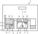
- FIG. 1 shows an inventive apparatus for additively manufacturing three-dimensional objects.
- FIG. 2 shows a bottom view of a powder chamber of an inventive powder module
- FIG. 3 shows a cross-sectional view of the powder chamber of FIGS. 1, 2 ;
- FIG. 4 shows an assembly of a suspension unit and a support unit according to a first embodiment
- FIG. 5 shows an assembly of a suspension unit and a support unit according to a second embodiment.
- FIG. 2 further shows that the powder module 5 comprises suspension units 14 that support the support units 13 against the carrying element 9 .
- the suspension units 14 generate a suspension force (indicated by arrow F) that moves the assigned support unit 13 against the powder chamber wall portion 11 generating a non-locating bearing, wherein the support units 12 provide a locating bearing against the powder chamber 10 .
- manufacturing tolerances of the powder chamber 10 and variances in the dimensions of the powder module 5 in particular of the carrying element 9 and the guide surfaces assigned to the carrying element 9 can be compensated by the non-locating bearing provided by the support units 13 supported by the suspension units 14 .
- FIG. 4 shows a detail of an exemplary non-locating bearing provided by three support units 13 that are supported via suspension units 14 , 15 , 16 .
- the uppermost support unit 13 is supported via two suspension units 14 , 15 that are connected in series.
- the two suspension units 14 , 15 may differ in the spring rate or the stiffness, respectively.
- the suspension units 14 , 15 may, for example, be built as mechanical spring elements, such as coil springs.
- the middle support unit 13 is supported via three suspension units 14 that are connected in parallel, wherein the three suspension units 14 may be the same suspension units 14 or differing from each other, for example regarding the spring rate or the stiffness, respectively.
- the lowermost support unit 13 is supported via a suspension unit 16 that is, for example, built as pneumatic element. Dependent on the pressure in the pneumatic element a suspension force is applied onto the lowermost support unit 13 .
- the support units 13 may be built as sliding elements, in particular sliding pads. Additionally, the support units 13 may provide a guide, for example by building the support units 13 as guiding rails that interact with a complementary element in the assigned wall portion 11 .
- FIG. 5 shows a bottom view of an assembly of two support units 13 and one suspension unit 14 analog to FIG. 2 .
- the single suspension unit 14 supports both support units 13 .
- both support units 13 can be arranged above each other or neighboring each other.
- an arbitrary number of support units 13 can be coupled and supported via one or more suspension units 14 , 15 , 16 .
Landscapes
- Chemical & Material Sciences (AREA)
- Engineering & Computer Science (AREA)
- Materials Engineering (AREA)
- Manufacturing & Machinery (AREA)
- Physics & Mathematics (AREA)
- Optics & Photonics (AREA)
- Mechanical Engineering (AREA)
- Powder Metallurgy (AREA)
- Magnetic Bearings And Hydrostatic Bearings (AREA)
Applications Claiming Priority (3)
| Application Number | Priority Date | Filing Date | Title |
|---|---|---|---|
| EP17203531.3 | 2017-11-24 | ||
| EP17203531 | 2017-11-24 | ||
| EP17203531.3A EP3488995A1 (de) | 2017-11-24 | 2017-11-24 | Pulvermodul |
Publications (2)
| Publication Number | Publication Date |
|---|---|
| US20190160752A1 US20190160752A1 (en) | 2019-05-30 |
| US11141917B2 true US11141917B2 (en) | 2021-10-12 |
Family
ID=60574382
Family Applications (1)
| Application Number | Title | Priority Date | Filing Date |
|---|---|---|---|
| US16/157,820 Active 2039-01-28 US11141917B2 (en) | 2017-11-24 | 2018-10-11 | Powder module |
Country Status (4)
| Country | Link |
|---|---|
| US (1) | US11141917B2 (de) |
| EP (1) | EP3488995A1 (de) |
| JP (2) | JP6622346B2 (de) |
| CN (1) | CN109834929A (de) |
Citations (6)
| Publication number | Priority date | Publication date | Assignee | Title |
|---|---|---|---|---|
| DE19905067A1 (de) | 1999-02-08 | 2000-08-10 | Matthias Fockele | Vorrichtung zur Herstellung eines Formkörpers durch schichtweises Aufbauen aus pulverförmigem, insbesondere metallischem Werkstoff |
| US7204684B2 (en) * | 2000-09-26 | 2007-04-17 | Ingo Ederer | Interchangeable container |
| EP2937163A1 (de) | 2014-03-13 | 2015-10-28 | Jeol Ltd. | Maschine und verfahren zur additivherstellung |
| CN105346090A (zh) | 2015-12-10 | 2016-02-24 | 合肥西锐三维打印科技有限公司 | 一种带有密封装置的成型平台 |
| CN105538725A (zh) | 2016-02-17 | 2016-05-04 | 李全贵 | 激光成型机 |
| US10252336B2 (en) * | 2016-06-29 | 2019-04-09 | Velo3D, Inc. | Three-dimensional printing and three-dimensional printers |
-
2017
- 2017-11-24 EP EP17203531.3A patent/EP3488995A1/de not_active Withdrawn
-
2018
- 2018-01-10 CN CN201810022010.3A patent/CN109834929A/zh active Pending
- 2018-03-30 JP JP2018067206A patent/JP6622346B2/ja not_active Expired - Fee Related
- 2018-10-11 US US16/157,820 patent/US11141917B2/en active Active
-
2019
- 2019-11-21 JP JP2019210380A patent/JP6928065B2/ja active Active
Patent Citations (6)
| Publication number | Priority date | Publication date | Assignee | Title |
|---|---|---|---|---|
| DE19905067A1 (de) | 1999-02-08 | 2000-08-10 | Matthias Fockele | Vorrichtung zur Herstellung eines Formkörpers durch schichtweises Aufbauen aus pulverförmigem, insbesondere metallischem Werkstoff |
| US7204684B2 (en) * | 2000-09-26 | 2007-04-17 | Ingo Ederer | Interchangeable container |
| EP2937163A1 (de) | 2014-03-13 | 2015-10-28 | Jeol Ltd. | Maschine und verfahren zur additivherstellung |
| CN105346090A (zh) | 2015-12-10 | 2016-02-24 | 合肥西锐三维打印科技有限公司 | 一种带有密封装置的成型平台 |
| CN105538725A (zh) | 2016-02-17 | 2016-05-04 | 李全贵 | 激光成型机 |
| US10252336B2 (en) * | 2016-06-29 | 2019-04-09 | Velo3D, Inc. | Three-dimensional printing and three-dimensional printers |
Non-Patent Citations (3)
| Title |
|---|
| European Search Opinion Corresponding to Application No. 17203531.3. |
| European Search Report Corresponding to Application No. 17203531 dated Jun. 20, 2018. |
| Japanese Office Action Corresponding to Application No. 2018067206 dated May 24, 2018. |
Also Published As
| Publication number | Publication date |
|---|---|
| CN109834929A (zh) | 2019-06-04 |
| US20190160752A1 (en) | 2019-05-30 |
| EP3488995A1 (de) | 2019-05-29 |
| JP6622346B2 (ja) | 2019-12-18 |
| JP2020032731A (ja) | 2020-03-05 |
| JP6928065B2 (ja) | 2021-09-01 |
| JP2019093697A (ja) | 2019-06-20 |
Similar Documents
| Publication | Publication Date | Title |
|---|---|---|
| US10106339B2 (en) | XY table for a linear transport system | |
| US20180056393A1 (en) | System for additive manufacturing of three-dimensional objects | |
| JP4351218B2 (ja) | 三次元造形製品の製造装置 | |
| US11141917B2 (en) | Powder module | |
| CN107530964B (zh) | 用于制造三维物体的设备 | |
| US20210331392A1 (en) | Apparatus for the additive manufacturing of a three-dimensional object | |
| US10105895B2 (en) | Apparatus for additively manufacturing of three-dimensional objects | |
| US11161305B2 (en) | Plant comprising at least one apparatus for additively manufacturing three-dimensional objects | |
| US6398101B1 (en) | Bi-directional compliant precision linear slide | |
| JP2023517170A (ja) | 粉体を出発材料とする積層造形システムのためのドクターブレードユニット | |
| EP3431210A1 (de) | Pulvermodul | |
| US10364842B2 (en) | Long travel air bearing linear stage | |
| EP3686009B1 (de) | Pulvermodul für eine vorrichtung zur generativen fertigung von dreidimensionalen objekten | |
| US20200114424A1 (en) | Application unit | |
| JP5368876B2 (ja) | 磁気ダンパーを有するエアスライド装置 | |
| US20190022790A1 (en) | Apparatus for manufacturing three-dimensional objects | |
| CN106808702A (zh) | 压紧治具 | |
| KR102017716B1 (ko) | 선형 이동 시스템 및 이를 포함하는 레이저 가공 장치 | |
| US20200122398A1 (en) | Apparatus for additively manufacturing three-dimensional objects | |
| US11123928B2 (en) | Plant comprising at least one apparatus for additively manufacturing three-dimensional objects | |
| US11820080B2 (en) | Apparatus for additively manufacturing three-dimensional objects | |
| US20190061247A1 (en) | Apparatus for additively manufacturing of three-dimensional objects | |
| KR100969373B1 (ko) | 전자빔 용접기용 지그장치 | |
| US20200254521A1 (en) | Method for operating an apparatus for additively manufacturing three-dimensional objects | |
| RU2753061C2 (ru) | Способ виброизоляции и виброизолирующий механизм для реализации способа |
Legal Events
| Date | Code | Title | Description |
|---|---|---|---|
| FEPP | Fee payment procedure |
Free format text: ENTITY STATUS SET TO UNDISCOUNTED (ORIGINAL EVENT CODE: BIG.); ENTITY STATUS OF PATENT OWNER: LARGE ENTITY |
|
| AS | Assignment |
Owner name: CL SCHUTZRECHTSVERWALTUNGS GMBH, GERMANY Free format text: ASSIGNMENT OF ASSIGNORS INTEREST;ASSIGNORS:HETZEL, RALF;SCHMIDBAUER, CHRISTOPH;REEL/FRAME:047152/0462 Effective date: 20171213 |
|
| STPP | Information on status: patent application and granting procedure in general |
Free format text: DOCKETED NEW CASE - READY FOR EXAMINATION |
|
| AS | Assignment |
Owner name: CONCEPT LASER GMBH, GERMANY Free format text: MERGER AND CHANGE OF NAME;ASSIGNORS:CL SCHUTZRECHTSVERWALTUNGS GMBH;CONCEPT LASER GMBH;REEL/FRAME:052048/0799 Effective date: 20190828 |
|
| STPP | Information on status: patent application and granting procedure in general |
Free format text: NON FINAL ACTION MAILED |
|
| STPP | Information on status: patent application and granting procedure in general |
Free format text: NOTICE OF ALLOWANCE MAILED -- APPLICATION RECEIVED IN OFFICE OF PUBLICATIONS |
|
| STPP | Information on status: patent application and granting procedure in general |
Free format text: DOCKETED NEW CASE - READY FOR EXAMINATION |
|
| STPP | Information on status: patent application and granting procedure in general |
Free format text: NOTICE OF ALLOWANCE MAILED -- APPLICATION RECEIVED IN OFFICE OF PUBLICATIONS |
|
| STPP | Information on status: patent application and granting procedure in general |
Free format text: PUBLICATIONS -- ISSUE FEE PAYMENT RECEIVED |
|
| STCF | Information on status: patent grant |
Free format text: PATENTED CASE |