US11092383B2 - Heat dissipation device - Google Patents
Heat dissipation device Download PDFInfo
- Publication number
- US11092383B2 US11092383B2 US16/251,074 US201916251074A US11092383B2 US 11092383 B2 US11092383 B2 US 11092383B2 US 201916251074 A US201916251074 A US 201916251074A US 11092383 B2 US11092383 B2 US 11092383B2
- Authority
- US
- United States
- Prior art keywords
- heat dissipation
- dissipation device
- top face
- heat
- chamber
- Prior art date
- Legal status (The legal status is an assumption and is not a legal conclusion. Google has not performed a legal analysis and makes no representation as to the accuracy of the status listed.)
- Active
Links
Images


Classifications
-
- H10W40/258—
-
- F—MECHANICAL ENGINEERING; LIGHTING; HEATING; WEAPONS; BLASTING
- F28—HEAT EXCHANGE IN GENERAL
- F28D—HEAT-EXCHANGE APPARATUS, NOT PROVIDED FOR IN ANOTHER SUBCLASS, IN WHICH THE HEAT-EXCHANGE MEDIA DO NOT COME INTO DIRECT CONTACT
- F28D1/00—Heat-exchange apparatus having stationary conduit assemblies for one heat-exchange medium only, the media being in contact with different sides of the conduit wall, in which the other heat-exchange medium is a large body of fluid, e.g. domestic or motor car radiators
- F28D1/02—Heat-exchange apparatus having stationary conduit assemblies for one heat-exchange medium only, the media being in contact with different sides of the conduit wall, in which the other heat-exchange medium is a large body of fluid, e.g. domestic or motor car radiators with heat-exchange conduits immersed in the body of fluid
- F28D1/03—Heat-exchange apparatus having stationary conduit assemblies for one heat-exchange medium only, the media being in contact with different sides of the conduit wall, in which the other heat-exchange medium is a large body of fluid, e.g. domestic or motor car radiators with heat-exchange conduits immersed in the body of fluid with plate-like or laminated conduits
-
- F—MECHANICAL ENGINEERING; LIGHTING; HEATING; WEAPONS; BLASTING
- F28—HEAT EXCHANGE IN GENERAL
- F28D—HEAT-EXCHANGE APPARATUS, NOT PROVIDED FOR IN ANOTHER SUBCLASS, IN WHICH THE HEAT-EXCHANGE MEDIA DO NOT COME INTO DIRECT CONTACT
- F28D15/00—Heat-exchange apparatus with the intermediate heat-transfer medium in closed tubes passing into or through the conduit walls ; Heat-exchange apparatus employing intermediate heat-transfer medium or bodies
- F28D15/02—Heat-exchange apparatus with the intermediate heat-transfer medium in closed tubes passing into or through the conduit walls ; Heat-exchange apparatus employing intermediate heat-transfer medium or bodies in which the medium condenses and evaporates, e.g. heat pipes
- F28D15/0233—Heat-exchange apparatus with the intermediate heat-transfer medium in closed tubes passing into or through the conduit walls ; Heat-exchange apparatus employing intermediate heat-transfer medium or bodies in which the medium condenses and evaporates, e.g. heat pipes the conduits having a particular shape, e.g. non-circular cross-section, annular
-
- F—MECHANICAL ENGINEERING; LIGHTING; HEATING; WEAPONS; BLASTING
- F28—HEAT EXCHANGE IN GENERAL
- F28D—HEAT-EXCHANGE APPARATUS, NOT PROVIDED FOR IN ANOTHER SUBCLASS, IN WHICH THE HEAT-EXCHANGE MEDIA DO NOT COME INTO DIRECT CONTACT
- F28D15/00—Heat-exchange apparatus with the intermediate heat-transfer medium in closed tubes passing into or through the conduit walls ; Heat-exchange apparatus employing intermediate heat-transfer medium or bodies
- F28D15/02—Heat-exchange apparatus with the intermediate heat-transfer medium in closed tubes passing into or through the conduit walls ; Heat-exchange apparatus employing intermediate heat-transfer medium or bodies in which the medium condenses and evaporates, e.g. heat pipes
- F28D15/0275—Arrangements for coupling heat-pipes together or with other structures, e.g. with base blocks; Heat pipe cores
-
- F—MECHANICAL ENGINEERING; LIGHTING; HEATING; WEAPONS; BLASTING
- F28—HEAT EXCHANGE IN GENERAL
- F28D—HEAT-EXCHANGE APPARATUS, NOT PROVIDED FOR IN ANOTHER SUBCLASS, IN WHICH THE HEAT-EXCHANGE MEDIA DO NOT COME INTO DIRECT CONTACT
- F28D15/00—Heat-exchange apparatus with the intermediate heat-transfer medium in closed tubes passing into or through the conduit walls ; Heat-exchange apparatus employing intermediate heat-transfer medium or bodies
- F28D15/02—Heat-exchange apparatus with the intermediate heat-transfer medium in closed tubes passing into or through the conduit walls ; Heat-exchange apparatus employing intermediate heat-transfer medium or bodies in which the medium condenses and evaporates, e.g. heat pipes
- F28D15/04—Heat-exchange apparatus with the intermediate heat-transfer medium in closed tubes passing into or through the conduit walls ; Heat-exchange apparatus employing intermediate heat-transfer medium or bodies in which the medium condenses and evaporates, e.g. heat pipes with tubes having a capillary structure
- F28D15/046—Heat-exchange apparatus with the intermediate heat-transfer medium in closed tubes passing into or through the conduit walls ; Heat-exchange apparatus employing intermediate heat-transfer medium or bodies in which the medium condenses and evaporates, e.g. heat pipes with tubes having a capillary structure characterised by the material or the construction of the capillary structure
-
- F—MECHANICAL ENGINEERING; LIGHTING; HEATING; WEAPONS; BLASTING
- F28—HEAT EXCHANGE IN GENERAL
- F28D—HEAT-EXCHANGE APPARATUS, NOT PROVIDED FOR IN ANOTHER SUBCLASS, IN WHICH THE HEAT-EXCHANGE MEDIA DO NOT COME INTO DIRECT CONTACT
- F28D20/00—Heat storage plants or apparatus in general; Regenerative heat-exchange apparatus not covered by groups F28D17/00 or F28D19/00
- F28D20/0056—Heat storage plants or apparatus in general; Regenerative heat-exchange apparatus not covered by groups F28D17/00 or F28D19/00 using solid heat storage material
-
- F—MECHANICAL ENGINEERING; LIGHTING; HEATING; WEAPONS; BLASTING
- F28—HEAT EXCHANGE IN GENERAL
- F28F—DETAILS OF HEAT-EXCHANGE AND HEAT-TRANSFER APPARATUS, OF GENERAL APPLICATION
- F28F3/00—Plate-like or laminated elements; Assemblies of plate-like or laminated elements
- F28F3/02—Elements or assemblies thereof with means for increasing heat-transfer area, e.g. with fins, with recesses, with corrugations
- F28F3/06—Elements or assemblies thereof with means for increasing heat-transfer area, e.g. with fins, with recesses, with corrugations the means being attachable to the element
-
- H—ELECTRICITY
- H01—ELECTRIC ELEMENTS
- H01L—SEMICONDUCTOR DEVICES NOT COVERED BY CLASS H10
- H01L23/00—Details of semiconductor or other solid state devices
- H01L23/34—Arrangements for cooling, heating, ventilating or temperature compensation ; Temperature sensing arrangements
- H01L23/36—Selection of materials, or shaping, to facilitate cooling or heating, e.g. heatsinks
- H01L23/373—Cooling facilitated by selection of materials for the device or materials for thermal expansion adaptation, e.g. carbon
-
- H10W40/25—
-
- H10W40/259—
-
- H10W40/73—
-
- F—MECHANICAL ENGINEERING; LIGHTING; HEATING; WEAPONS; BLASTING
- F28—HEAT EXCHANGE IN GENERAL
- F28D—HEAT-EXCHANGE APPARATUS, NOT PROVIDED FOR IN ANOTHER SUBCLASS, IN WHICH THE HEAT-EXCHANGE MEDIA DO NOT COME INTO DIRECT CONTACT
- F28D1/00—Heat-exchange apparatus having stationary conduit assemblies for one heat-exchange medium only, the media being in contact with different sides of the conduit wall, in which the other heat-exchange medium is a large body of fluid, e.g. domestic or motor car radiators
- F28D1/02—Heat-exchange apparatus having stationary conduit assemblies for one heat-exchange medium only, the media being in contact with different sides of the conduit wall, in which the other heat-exchange medium is a large body of fluid, e.g. domestic or motor car radiators with heat-exchange conduits immersed in the body of fluid
- F28D1/03—Heat-exchange apparatus having stationary conduit assemblies for one heat-exchange medium only, the media being in contact with different sides of the conduit wall, in which the other heat-exchange medium is a large body of fluid, e.g. domestic or motor car radiators with heat-exchange conduits immersed in the body of fluid with plate-like or laminated conduits
- F28D1/0308—Heat-exchange apparatus having stationary conduit assemblies for one heat-exchange medium only, the media being in contact with different sides of the conduit wall, in which the other heat-exchange medium is a large body of fluid, e.g. domestic or motor car radiators with heat-exchange conduits immersed in the body of fluid with plate-like or laminated conduits the conduits being formed by paired plates touching each other
-
- F—MECHANICAL ENGINEERING; LIGHTING; HEATING; WEAPONS; BLASTING
- F28—HEAT EXCHANGE IN GENERAL
- F28D—HEAT-EXCHANGE APPARATUS, NOT PROVIDED FOR IN ANOTHER SUBCLASS, IN WHICH THE HEAT-EXCHANGE MEDIA DO NOT COME INTO DIRECT CONTACT
- F28D15/00—Heat-exchange apparatus with the intermediate heat-transfer medium in closed tubes passing into or through the conduit walls ; Heat-exchange apparatus employing intermediate heat-transfer medium or bodies
- F28D15/02—Heat-exchange apparatus with the intermediate heat-transfer medium in closed tubes passing into or through the conduit walls ; Heat-exchange apparatus employing intermediate heat-transfer medium or bodies in which the medium condenses and evaporates, e.g. heat pipes
- F28D15/04—Heat-exchange apparatus with the intermediate heat-transfer medium in closed tubes passing into or through the conduit walls ; Heat-exchange apparatus employing intermediate heat-transfer medium or bodies in which the medium condenses and evaporates, e.g. heat pipes with tubes having a capillary structure
-
- F—MECHANICAL ENGINEERING; LIGHTING; HEATING; WEAPONS; BLASTING
- F28—HEAT EXCHANGE IN GENERAL
- F28F—DETAILS OF HEAT-EXCHANGE AND HEAT-TRANSFER APPARATUS, OF GENERAL APPLICATION
- F28F21/00—Constructions of heat-exchange apparatus characterised by the selection of particular materials
- F28F21/04—Constructions of heat-exchange apparatus characterised by the selection of particular materials of ceramic; of concrete; of natural stone
-
- F—MECHANICAL ENGINEERING; LIGHTING; HEATING; WEAPONS; BLASTING
- F28—HEAT EXCHANGE IN GENERAL
- F28F—DETAILS OF HEAT-EXCHANGE AND HEAT-TRANSFER APPARATUS, OF GENERAL APPLICATION
- F28F21/00—Constructions of heat-exchange apparatus characterised by the selection of particular materials
- F28F21/08—Constructions of heat-exchange apparatus characterised by the selection of particular materials of metal
- F28F21/081—Heat exchange elements made from metals or metal alloys
- F28F21/082—Heat exchange elements made from metals or metal alloys from steel or ferrous alloys
- F28F21/083—Heat exchange elements made from metals or metal alloys from steel or ferrous alloys from stainless steel
-
- F—MECHANICAL ENGINEERING; LIGHTING; HEATING; WEAPONS; BLASTING
- F28—HEAT EXCHANGE IN GENERAL
- F28F—DETAILS OF HEAT-EXCHANGE AND HEAT-TRANSFER APPARATUS, OF GENERAL APPLICATION
- F28F21/00—Constructions of heat-exchange apparatus characterised by the selection of particular materials
- F28F21/08—Constructions of heat-exchange apparatus characterised by the selection of particular materials of metal
- F28F21/081—Heat exchange elements made from metals or metal alloys
- F28F21/084—Heat exchange elements made from metals or metal alloys from aluminium or aluminium alloys
-
- F—MECHANICAL ENGINEERING; LIGHTING; HEATING; WEAPONS; BLASTING
- F28—HEAT EXCHANGE IN GENERAL
- F28F—DETAILS OF HEAT-EXCHANGE AND HEAT-TRANSFER APPARATUS, OF GENERAL APPLICATION
- F28F21/00—Constructions of heat-exchange apparatus characterised by the selection of particular materials
- F28F21/08—Constructions of heat-exchange apparatus characterised by the selection of particular materials of metal
- F28F21/081—Heat exchange elements made from metals or metal alloys
- F28F21/085—Heat exchange elements made from metals or metal alloys from copper or copper alloys
-
- F—MECHANICAL ENGINEERING; LIGHTING; HEATING; WEAPONS; BLASTING
- F28—HEAT EXCHANGE IN GENERAL
- F28F—DETAILS OF HEAT-EXCHANGE AND HEAT-TRANSFER APPARATUS, OF GENERAL APPLICATION
- F28F21/00—Constructions of heat-exchange apparatus characterised by the selection of particular materials
- F28F21/08—Constructions of heat-exchange apparatus characterised by the selection of particular materials of metal
- F28F21/081—Heat exchange elements made from metals or metal alloys
- F28F21/086—Heat exchange elements made from metals or metal alloys from titanium or titanium alloys
-
- F—MECHANICAL ENGINEERING; LIGHTING; HEATING; WEAPONS; BLASTING
- F28—HEAT EXCHANGE IN GENERAL
- F28F—DETAILS OF HEAT-EXCHANGE AND HEAT-TRANSFER APPARATUS, OF GENERAL APPLICATION
- F28F2255/00—Heat exchanger elements made of materials having special features or resulting from particular manufacturing processes
- F28F2255/18—Heat exchanger elements made of materials having special features or resulting from particular manufacturing processes sintered
-
- F—MECHANICAL ENGINEERING; LIGHTING; HEATING; WEAPONS; BLASTING
- F28—HEAT EXCHANGE IN GENERAL
- F28F—DETAILS OF HEAT-EXCHANGE AND HEAT-TRANSFER APPARATUS, OF GENERAL APPLICATION
- F28F2275/00—Fastening; Joining
- F28F2275/02—Fastening; Joining by using bonding materials; by embedding elements in particular materials
-
- F—MECHANICAL ENGINEERING; LIGHTING; HEATING; WEAPONS; BLASTING
- F28—HEAT EXCHANGE IN GENERAL
- F28F—DETAILS OF HEAT-EXCHANGE AND HEAT-TRANSFER APPARATUS, OF GENERAL APPLICATION
- F28F2275/00—Fastening; Joining
- F28F2275/06—Fastening; Joining by welding
- F28F2275/061—Fastening; Joining by welding by diffusion bonding
-
- F—MECHANICAL ENGINEERING; LIGHTING; HEATING; WEAPONS; BLASTING
- F28—HEAT EXCHANGE IN GENERAL
- F28F—DETAILS OF HEAT-EXCHANGE AND HEAT-TRANSFER APPARATUS, OF GENERAL APPLICATION
- F28F2275/00—Fastening; Joining
- F28F2275/06—Fastening; Joining by welding
- F28F2275/067—Fastening; Joining by welding by laser welding
-
- Y—GENERAL TAGGING OF NEW TECHNOLOGICAL DEVELOPMENTS; GENERAL TAGGING OF CROSS-SECTIONAL TECHNOLOGIES SPANNING OVER SEVERAL SECTIONS OF THE IPC; TECHNICAL SUBJECTS COVERED BY FORMER USPC CROSS-REFERENCE ART COLLECTIONS [XRACs] AND DIGESTS
- Y02—TECHNOLOGIES OR APPLICATIONS FOR MITIGATION OR ADAPTATION AGAINST CLIMATE CHANGE
- Y02E—REDUCTION OF GREENHOUSE GAS [GHG] EMISSIONS, RELATED TO ENERGY GENERATION, TRANSMISSION OR DISTRIBUTION
- Y02E60/00—Enabling technologies; Technologies with a potential or indirect contribution to GHG emissions mitigation
- Y02E60/14—Thermal energy storage
Definitions
- the present invention relates generally to a heat dissipation device, and more particularly to a heat dissipation device, which can greatly enhance the horizontal heat dissipation effect as a whole.
- a vapor chamber is a kind of heat dissipation device often applied to heat dissipation field.
- the vapor chamber is often made of copper, aluminum, stainless steel, etc. In manufacturing, these materials are apt to cause potential difference, which will result in the phenomenon of potential difference corrosion, etc.
- the conventional vapor chamber made of copper, aluminum or stainless steel is applied to large-scale industrial equipment, in order to have sufficient strength, the vapor chamber generally has a huge volume and quite heavy weight.
- the vapor chamber is applied to a handheld device such as an intelligent mobile phone or tablet, it is necessary to manufacture an extremely thin vapor chamber. Under such circumstance, the vapor chamber is often too thin to have sufficient strength. Therefore, in recent years, some manufacturers have manufactured advanced heat dissipation devices with titanium material for application to heat dissipation field.
- Titanium is a metal material having the properties of lightweight, high structural strength and anticorrosion. Therefore, titanium has been widely used in various fields. However, in comparison with copper and aluminum materials, the thermal conductivity (also referred to as K value) of titanium is slightly lower than that of copper and aluminum materials. In addition, the heat dissipation device made of titanium has a relatively poor heat conduction effect in horizontal direction.
- a heat dissipation device 1 such as a vapor chamber
- titanium and additionally attach at least one heat conduction member 11 (such as graphite sheet, heat pipe, copper plate, etc.) to the outer flange 10 of the heat dissipation device 1 so as to enhance the heat conduction effect in horizontal direction.
- the flange 10 is a section formed along the outer peripheries of the two plate bodies in such a manner that after two plate bodies of the vapor chamber are mated with each other, the outer peripheries of the two plate bodies are connected and sealed with each other by means of heating (such as welding) or pressurization.
- the working fluid 13 filled in the vapor chamber cannot flow to the flange 10 so that the flange 10 is a void area without vapor-liquid circulation effect.
- the conventional vapor chamber is simply improved by means of attaching the heat conduction member 11 to the flange 10 of the vapor chamber without directly contacting the working area of the vapor chamber with heat conduction effect, (that is, the area of the chamber 12 with the vapor-liquid circulation effect of the working fluid 13 as shown in FIG. 1B ). Therefore, actually, the heat conduction member 11 additionally attaching to the flange 10 can hardly enhance the heat conduction effect in horizontal direction. As a result, the heat dissipation effect of the entire heat dissipation device 1 cannot be enhanced.
- the heat dissipation device of the present invention includes a main body and at least one heat conduction member.
- the main body has a top face.
- One end of the heat conduction member is correspondingly in contact and connection with the top face.
- the heat dissipation device of the present invention includes a main body and at least one heat conduction member.
- the main body has a top face.
- a periphery of the top face has a connection section.
- One end of the heat conduction member is correspondingly in contact and connection with the top face or the connection section.
- the main body has an upper plate and a lower plate.
- the upper and lower plates are correspondingly mated with each other to together define a chamber.
- a working fluid is filled in the chamber.
- the chamber is an area where the vapor-liquid circulation of the working fluid is performed.
- the main body is further formed with a flange, which is an outermost periphery of the main body for connection and sealing of the main body. Therefore, the flange is a void area without vapor-liquid circulation effect.
- one end of the heat conduction member extends to contact and connect with the top face or the connection section.
- One face of the heat dissipation device is in contact with and attaches to a heat source to absorb the heat thereof.
- the vapor-liquid circulation of the working fluid in the chamber is performed so as to conduct and dissipate the heat.
- the heat can be transferred from one end to the other end of the heat conduction member in contact with and attached to the top face or the connection section so as to enhance the heat conduction and dissipation effect in the horizontal direction.
- the horizontal heat conduction and dissipation effect of the heat dissipation device is greatly enhanced to improve the shortcoming of the conventional heat dissipation effect that the heat conduction member is simply attached to the flange of the main body and fails to achieve any heat transfer effect.
- FIG. 1A is a perspective assembled view of a conventional heat dissipation device
- FIG. 1B is a sectional view of the conventional heat dissipation device
- FIG. 2 is a perspective exploded view of a first embodiment of the heat dissipation device of the present invention
- FIG. 3 is a perspective assembled view of the first embodiment of the heat dissipation device of the present invention.
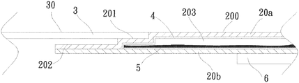
- FIG. 4 is a sectional view of the first embodiment of the heat dissipation device of the present invention.
- FIG. 5 is a sectional view of a second embodiment of the heat dissipation device of the present invention.
- FIG. 2 is a perspective exploded view of a first embodiment of the heat dissipation device of the present invention.
- FIG. 3 is a perspective assembled view of the first embodiment of the heat dissipation device of the present invention.
- FIG. 4 is a sectional view of the first embodiment of the heat dissipation device of the present invention.
- the first embodiment of the heat dissipation device 2 of the present invention includes a main body 20 and at least one heat conduction member 3 .
- the main body 20 has a top face 200 .
- a periphery of the top face 200 has a connection section 201 .
- the main body 20 is, but not limited to, a vapor chamber for illustration purposes.
- the main body 20 can be a heat pipe, a heat plate or any other heat dissipation device.
- the main body 20 has an upper plate 20 a and a lower plate 20 b .
- the upper and lower plates 20 a , 20 b are correspondingly mated with each other to together define a chamber 203 .
- the top face 200 and the connection section 201 are respectively correspondingly disposed on an outer side of the chamber 203 .
- a capillary structure 4 and a working fluid 5 are disposed in the chamber 203 .
- the upper and lower plates 20 a , 20 b can be made of the same material or different materials and are assembled with each other to form the main body 20 .
- the material of the upper and lower plates 20 a , 20 b is selected from a group consisting of gold, silver, copper, aluminum, iron, stainless steel, ceramic material, commercial pure titanium and titanium alloy.
- An outer face of the upper plate 20 a (that is, the top face) is defined as a condensation side, while an outer face of the lower plate 20 b , (that is, the bottom face) is defined as a heat
- one end of the heat conduction member 3 is correspondingly in contact and connection with the top face 200 .
- the heat conduction member 3 is selectively graphite or graphene.
- the heat conduction member 3 is correspondingly in contact with and attaches to the top face 200 by means of adhesion, diffusion bonding, welding, sintering or laser welding.
- the working fluid 5 in the chamber 203 is positioned where the vapor-liquid circulation is performed.
- the main body 20 is further formed with a flange 202 as an outermost periphery of the main body 20 for connection and sealing of the main body 20 . Therefore, the flange 202 is a void area without vapor-liquid circulation effect.
- the outer face of the lower plate 20 b , (that is, the heat absorption side) of the heat dissipation device 2 is in contact with and attaches to a heat source 6 to absorb the heat thereof.
- the vapor-liquid circulation of the working fluid in the chamber 203 is performed so as to conduct and dissipate the heat.
- the heat can be transferred from one end to the other end of the heat conduction member 3 attached to the top face 200 so as to enhance the heat conduction and dissipation effect in the horizontal direction of the main body 20 .
- the other end of the heat conduction member 3 can be further connected to a heat dissipation component (not shown) to dissipate the heat.
- the heat dissipation component can be a heat sink or a radiating fin assembly. Accordingly, the heat dissipation effect of the entire heat dissipation device 2 of the present invention can be greatly enhanced to improve the shortcoming of the conventional heat dissipation device that the heat conduction member 3 is simply attached to the flange 202 of the main body 20 and fails to achieve any heat transfer effect.
- the number and size of the heat conduction member 3 one end of which is in contact and connection with the top face 200 are not limited.
- the number and size of the heat conduction member 3 can be adjusted in accordance with the requirement of a user for the arrangement.
- FIG. 5 is a sectional view of a second embodiment of the heat dissipation device of the present invention.
- the second embodiment is partially identical to the first embodiment in structure and thus will not be redundantly described hereinafter.
- the second embodiment is different from the first embodiment in that one end of the heat conduction member 3 is correspondingly in contact and connection with the connection section 201 .
- the connection section 201 has the form of a stepped structure.
- the flange 202 further outward extends from the stepped structure.
- the stepped structure is continuously arranged or discontinuously arranged. In this embodiment, as shown in the drawing, the stepped structure is continuously arranged.
- a first face 30 of the heat conduction member 3 is correspondingly flush with the top face 200 of the main body 20 (as shown in FIG. 5 ).
- the first face 30 of the heat conduction member 3 is not flush with the top face 200 of the main body 20 , that is, the first face 30 is selectively lower than or higher than the top face 200 (not shown).
- the present invention has the following advantages:
Landscapes
- Engineering & Computer Science (AREA)
- Physics & Mathematics (AREA)
- Thermal Sciences (AREA)
- Mechanical Engineering (AREA)
- General Engineering & Computer Science (AREA)
- Life Sciences & Earth Sciences (AREA)
- Sustainable Development (AREA)
- Materials Engineering (AREA)
- Chemical & Material Sciences (AREA)
- Condensed Matter Physics & Semiconductors (AREA)
- General Physics & Mathematics (AREA)
- Computer Hardware Design (AREA)
- Microelectronics & Electronic Packaging (AREA)
- Power Engineering (AREA)
- Cooling Or The Like Of Semiconductors Or Solid State Devices (AREA)
- Cooling Or The Like Of Electrical Apparatus (AREA)
Abstract
Description
- 1. The horizontal heat conduction and dissipation effect is greatly enhanced.
- 2. The heat dissipation effect of the entire heat dissipation device is greatly enhanced.
Claims (6)
Priority Applications (1)
| Application Number | Priority Date | Filing Date | Title |
|---|---|---|---|
| US16/251,074 US11092383B2 (en) | 2019-01-18 | 2019-01-18 | Heat dissipation device |
Applications Claiming Priority (1)
| Application Number | Priority Date | Filing Date | Title |
|---|---|---|---|
| US16/251,074 US11092383B2 (en) | 2019-01-18 | 2019-01-18 | Heat dissipation device |
Publications (2)
| Publication Number | Publication Date |
|---|---|
| US20200232712A1 US20200232712A1 (en) | 2020-07-23 |
| US11092383B2 true US11092383B2 (en) | 2021-08-17 |
Family
ID=71608578
Family Applications (1)
| Application Number | Title | Priority Date | Filing Date |
|---|---|---|---|
| US16/251,074 Active US11092383B2 (en) | 2019-01-18 | 2019-01-18 | Heat dissipation device |
Country Status (1)
| Country | Link |
|---|---|
| US (1) | US11092383B2 (en) |
Cited By (1)
| Publication number | Priority date | Publication date | Assignee | Title |
|---|---|---|---|---|
| US20220205733A1 (en) * | 2016-06-15 | 2022-06-30 | Delta Electronics, Inc. | Heat dissipation device |
Families Citing this family (2)
| Publication number | Priority date | Publication date | Assignee | Title |
|---|---|---|---|---|
| US11092383B2 (en) * | 2019-01-18 | 2021-08-17 | Asia Vital Components Co., Ltd. | Heat dissipation device |
| JP6934093B1 (en) * | 2020-07-13 | 2021-09-08 | レノボ・シンガポール・プライベート・リミテッド | Electronic equipment and cooling modules |
Citations (71)
| Publication number | Priority date | Publication date | Assignee | Title |
|---|---|---|---|---|
| US5076351A (en) * | 1989-07-19 | 1991-12-31 | Showa Aluminum Corporation | Heat pipe |
| US20050178532A1 (en) * | 2004-02-18 | 2005-08-18 | Huang Meng-Cheng | Structure for expanding thermal conducting performance of heat sink |
| US20070012431A1 (en) * | 2005-06-27 | 2007-01-18 | Hideyuki Miyahara | Plate type heat exchanger and method of manufacturing the same |
| CN201119229Y (en) | 2007-10-26 | 2008-09-17 | 北京工业大学 | Heat dissipation device integrated with flat heat pipe |
| US20080251239A1 (en) * | 2007-04-10 | 2008-10-16 | Fujikura Ltd. | Heat sink |
| US20100006267A1 (en) * | 2008-07-14 | 2010-01-14 | Meyer Iv George Anthony | Covered plate-type heat pipe |
| CN101819001A (en) | 2009-02-27 | 2010-09-01 | 陈文进 | Superconducting element structure |
| TW201102605A (en) | 2009-07-10 | 2011-01-16 | Foxconn Tech Co Ltd | Heat spreader and method for manufacturing the same |
| US20110088873A1 (en) * | 2009-10-15 | 2011-04-21 | Asia Vital Components Co., Ltd. | Support structure for flat-plate heat pipe |
| US20110174474A1 (en) * | 2010-01-20 | 2011-07-21 | Juei-Khai Liu | Vapor chamber and method for manufacturing the same |
| US20110186268A1 (en) * | 2010-02-04 | 2011-08-04 | Asia Vital Components Co., Ltd. | Flat type heat pipe device |
| US20110259554A1 (en) * | 2010-04-26 | 2011-10-27 | Asia Vital Components Co., Ltd. | Flat plate heat pipe and method for manufacturing the same |
| US20120285662A1 (en) * | 2011-05-10 | 2012-11-15 | Celsia Technologies Taiwan, I | Vapor chamber with improved sealed opening |
| CN103025118A (en) | 2011-09-21 | 2013-04-03 | 奇鋐科技股份有限公司 | Heat sink and method for manufacturing the same |
| US20130199757A1 (en) * | 2012-02-03 | 2013-08-08 | Celsia Technologies Taiwan, Inc. | Heat-dissipating module having loop-type vapor chamber |
| US20140138057A1 (en) * | 2012-11-18 | 2014-05-22 | Chin-Hsing Horng | Structure of low-profile heat pipe |
| US20140182819A1 (en) * | 2013-01-01 | 2014-07-03 | Asia Vital Components Co., Ltd. | Heat dissipating device |
| US20150083371A1 (en) * | 2013-09-24 | 2015-03-26 | Asia Vital Components Co., Ltd. | Heat dissipation structure for hand-held mobile device |
| US20150129175A1 (en) * | 2012-11-13 | 2015-05-14 | Delta Electronics, Inc. | Thermosyphon heat sink |
| US20150185793A1 (en) * | 2013-12-31 | 2015-07-02 | Asia Vital Components Co., Ltd. | Heat dissipation structure of mobile device |
| US20160003555A1 (en) * | 2014-07-04 | 2016-01-07 | Cooler Master Co., Ltd. | Heat dissipater having capillary component |
| US20160091259A1 (en) * | 2014-09-26 | 2016-03-31 | Asia Vital Components Co., Ltd. | Vapor chamber structure |
| US20160131437A1 (en) * | 2014-11-12 | 2016-05-12 | Asia Vital Components Co., Ltd. | Thin heat pipe structure |
| US20160131436A1 (en) * | 2014-11-12 | 2016-05-12 | Asia Vital Components Co., Ltd. | Heat pipe structure |
| US20160187074A1 (en) * | 2014-12-25 | 2016-06-30 | Asia Vital Components Co., Ltd. | Supporting structure for vapor chamber |
| US20160219756A1 (en) * | 2015-01-28 | 2016-07-28 | Cooler Master Co., Ltd. | Heat sink structure with heat exchange mechanism |
| US20160223267A1 (en) * | 2015-02-02 | 2016-08-04 | Asia Vital Components Co., Ltd. | Flat-plate heat pipe structure |
| US9453688B2 (en) * | 2013-09-24 | 2016-09-27 | Asia Vital Components Co., Ltd. | Heat dissipation unit |
| CN205678635U (en) | 2016-05-23 | 2016-11-09 | 张文锦 | Improved high-power road lighting LED lamp set |
| US20170023307A1 (en) * | 2015-07-21 | 2017-01-26 | Chaun-Choung Technology Corp. | Vapor chamber having no gas discharging protrusion and manufacturing method thereof |
| US20170122671A1 (en) * | 2015-10-28 | 2017-05-04 | Taiwan Microloops Corp. | Vapor chamber and upper housing thereof |
| US20170122672A1 (en) * | 2015-10-28 | 2017-05-04 | Taiwan Microloops Corp. | Vapor chamber and manufacturing method thereof |
| US20170153064A1 (en) * | 2015-12-01 | 2017-06-01 | Asia Vital Components Co., Ltd. | Heat dissipation unit |
| US9685636B2 (en) * | 2014-07-23 | 2017-06-20 | Samsung Display Co., Ltd. | Composite sheet and display device comprising the same |
| US20170248374A1 (en) * | 2016-02-25 | 2017-08-31 | Asia Vital Components Co., Ltd. | Vapor chamber structure |
| US20170254600A1 (en) * | 2016-03-01 | 2017-09-07 | Cooler Master Co., Ltd. | Heat pipe module and heat dissipating device using the same |
| US20170268835A1 (en) * | 2016-03-21 | 2017-09-21 | Taiwan Microloops Corp. | Dual material vapor chamber and upper shell thereof |
| US9772143B2 (en) * | 2013-04-25 | 2017-09-26 | Asia Vital Components Co., Ltd. | Thermal module |
| US20170292793A1 (en) * | 2016-04-07 | 2017-10-12 | Cooler Master Co., Ltd. | Thermal conducting structure |
| CN107407531A (en) | 2015-03-26 | 2017-11-28 | 株式会社村田制作所 | Sheet heat pipe |
| US20170343298A1 (en) * | 2016-05-27 | 2017-11-30 | Asia Vital Components Co., Ltd. | Heat dissipation component |
| US20170367219A1 (en) * | 2016-06-16 | 2017-12-21 | Asia Vital Components Co., Ltd. | Vapor chamber structure |
| US20180031330A1 (en) * | 2016-08-01 | 2018-02-01 | California Institute Of Technology | Multi-Phase Thermal Control Apparatus, Evaporators and Methods of Manufacture Thereof |
| US20180100708A1 (en) * | 2016-06-16 | 2018-04-12 | Asia Vital Components Co., Ltd. | Vapor chamber structure |
| US20180106552A1 (en) * | 2016-10-14 | 2018-04-19 | Taiwan Microloops Corp. | Vapor chamber and heat pipe combined structure and combining method thereof |
| US20180164043A1 (en) * | 2016-12-14 | 2018-06-14 | Shinko Electric Industries Co., Ltd. | Heat pipe |
| US10012445B2 (en) * | 2016-09-08 | 2018-07-03 | Taiwan Microloops Corp. | Vapor chamber and heat pipe combined structure |
| CN108362148A (en) | 2018-01-29 | 2018-08-03 | 北京雷格讯电子股份有限公司 | Combined type cold plate |
| CN108362144A (en) | 2018-01-29 | 2018-08-03 | 北京雷格讯电子股份有限公司 | Compound slab heat pipe |
| CN108716871A (en) | 2018-07-09 | 2018-10-30 | 奇鋐科技股份有限公司 | Heat dissipation element and manufacturing method thereof |
| US20180320997A1 (en) * | 2017-05-05 | 2018-11-08 | Forcecon Technology Co., Ltd. | Temperature-uniforming plate with supporting effect |
| CN108882644A (en) | 2018-07-25 | 2018-11-23 | 奇鋐科技股份有限公司 | Heat radiation unit |
| US20180372418A1 (en) * | 2017-06-22 | 2018-12-27 | Asia Vital Components Co., Ltd. | Heat Dissipation Device |
| US20180372419A1 (en) * | 2017-04-11 | 2018-12-27 | Cooler Master Co., Ltd. | Heat transfer device |
| US20180372431A1 (en) * | 2017-06-22 | 2018-12-27 | Asia Vital Components Co., Ltd. | Heat dissipation device |
| US20190145712A1 (en) * | 2017-11-14 | 2019-05-16 | Asia Vital Components Co., Ltd. | Straight-through structure of heat dissipation unit |
| US20190162480A1 (en) * | 2017-11-29 | 2019-05-30 | Asia Vital Components Co., Ltd. | Airtight penetration structure for heat dissipation device |
| US20190204019A1 (en) * | 2018-01-03 | 2019-07-04 | Asia Vital Components (China) Co., Ltd. | Heat dissipation device |
| US20190204020A1 (en) * | 2018-01-03 | 2019-07-04 | Asia Vital Components (China) Co., Ltd. | Manufacturing method of heat dissipation device |
| US20190226770A1 (en) * | 2018-01-23 | 2019-07-25 | Cooler Master Co., Ltd. | Vapor chamber |
| US20190242654A1 (en) * | 2018-02-06 | 2019-08-08 | Shinko Electric Industries Co., Ltd. | Loop heat pipe |
| US20190285357A1 (en) * | 2018-03-19 | 2019-09-19 | Asia Vital Components Co., Ltd. | Middle member of heat dissipation device and the heat dissipation device |
| US20190343021A1 (en) * | 2018-05-07 | 2019-11-07 | Asia Vital Components Co., Ltd. | Heat dissipation unit connection reinforcement structure |
| CN209639571U (en) | 2019-01-03 | 2019-11-15 | 奇鋐科技股份有限公司 | heat sink |
| US20190376747A1 (en) * | 2018-06-08 | 2019-12-12 | Cooler Master Co., Ltd. | Vapor chamber and manufacturing method for the same |
| US20200025457A1 (en) * | 2018-07-22 | 2020-01-23 | Asia Vital Components Co., Ltd. | Heat dissipation component |
| US20200045851A1 (en) * | 2018-08-05 | 2020-02-06 | Asia Vital Components Co., Ltd. | Heat dissipation unit |
| US20200060044A1 (en) * | 2017-04-28 | 2020-02-20 | Murata Manufacturing Co., Ltd. | Vapor chamber |
| US20200068745A1 (en) * | 2018-08-22 | 2020-02-27 | Asia Vital Components Co., Ltd. | Heat dissipation structure of electronic device |
| US20200088472A1 (en) * | 2018-09-18 | 2020-03-19 | Asia Vital Components Co., Ltd. | Heat dissipation unit |
| US20200232712A1 (en) * | 2019-01-18 | 2020-07-23 | Asia Vital Components Co., Ltd. | Heat dissipation device |
-
2019
- 2019-01-18 US US16/251,074 patent/US11092383B2/en active Active
Patent Citations (71)
| Publication number | Priority date | Publication date | Assignee | Title |
|---|---|---|---|---|
| US5076351A (en) * | 1989-07-19 | 1991-12-31 | Showa Aluminum Corporation | Heat pipe |
| US20050178532A1 (en) * | 2004-02-18 | 2005-08-18 | Huang Meng-Cheng | Structure for expanding thermal conducting performance of heat sink |
| US20070012431A1 (en) * | 2005-06-27 | 2007-01-18 | Hideyuki Miyahara | Plate type heat exchanger and method of manufacturing the same |
| US20080251239A1 (en) * | 2007-04-10 | 2008-10-16 | Fujikura Ltd. | Heat sink |
| CN201119229Y (en) | 2007-10-26 | 2008-09-17 | 北京工业大学 | Heat dissipation device integrated with flat heat pipe |
| US20100006267A1 (en) * | 2008-07-14 | 2010-01-14 | Meyer Iv George Anthony | Covered plate-type heat pipe |
| CN101819001A (en) | 2009-02-27 | 2010-09-01 | 陈文进 | Superconducting element structure |
| TW201102605A (en) | 2009-07-10 | 2011-01-16 | Foxconn Tech Co Ltd | Heat spreader and method for manufacturing the same |
| US20110088873A1 (en) * | 2009-10-15 | 2011-04-21 | Asia Vital Components Co., Ltd. | Support structure for flat-plate heat pipe |
| US20110174474A1 (en) * | 2010-01-20 | 2011-07-21 | Juei-Khai Liu | Vapor chamber and method for manufacturing the same |
| US20110186268A1 (en) * | 2010-02-04 | 2011-08-04 | Asia Vital Components Co., Ltd. | Flat type heat pipe device |
| US20110259554A1 (en) * | 2010-04-26 | 2011-10-27 | Asia Vital Components Co., Ltd. | Flat plate heat pipe and method for manufacturing the same |
| US20120285662A1 (en) * | 2011-05-10 | 2012-11-15 | Celsia Technologies Taiwan, I | Vapor chamber with improved sealed opening |
| CN103025118A (en) | 2011-09-21 | 2013-04-03 | 奇鋐科技股份有限公司 | Heat sink and method for manufacturing the same |
| US20130199757A1 (en) * | 2012-02-03 | 2013-08-08 | Celsia Technologies Taiwan, Inc. | Heat-dissipating module having loop-type vapor chamber |
| US20150129175A1 (en) * | 2012-11-13 | 2015-05-14 | Delta Electronics, Inc. | Thermosyphon heat sink |
| US20140138057A1 (en) * | 2012-11-18 | 2014-05-22 | Chin-Hsing Horng | Structure of low-profile heat pipe |
| US20140182819A1 (en) * | 2013-01-01 | 2014-07-03 | Asia Vital Components Co., Ltd. | Heat dissipating device |
| US9772143B2 (en) * | 2013-04-25 | 2017-09-26 | Asia Vital Components Co., Ltd. | Thermal module |
| US20150083371A1 (en) * | 2013-09-24 | 2015-03-26 | Asia Vital Components Co., Ltd. | Heat dissipation structure for hand-held mobile device |
| US9453688B2 (en) * | 2013-09-24 | 2016-09-27 | Asia Vital Components Co., Ltd. | Heat dissipation unit |
| US20150185793A1 (en) * | 2013-12-31 | 2015-07-02 | Asia Vital Components Co., Ltd. | Heat dissipation structure of mobile device |
| US20160003555A1 (en) * | 2014-07-04 | 2016-01-07 | Cooler Master Co., Ltd. | Heat dissipater having capillary component |
| US9685636B2 (en) * | 2014-07-23 | 2017-06-20 | Samsung Display Co., Ltd. | Composite sheet and display device comprising the same |
| US20160091259A1 (en) * | 2014-09-26 | 2016-03-31 | Asia Vital Components Co., Ltd. | Vapor chamber structure |
| US20160131437A1 (en) * | 2014-11-12 | 2016-05-12 | Asia Vital Components Co., Ltd. | Thin heat pipe structure |
| US20160131436A1 (en) * | 2014-11-12 | 2016-05-12 | Asia Vital Components Co., Ltd. | Heat pipe structure |
| US20160187074A1 (en) * | 2014-12-25 | 2016-06-30 | Asia Vital Components Co., Ltd. | Supporting structure for vapor chamber |
| US20160219756A1 (en) * | 2015-01-28 | 2016-07-28 | Cooler Master Co., Ltd. | Heat sink structure with heat exchange mechanism |
| US20160223267A1 (en) * | 2015-02-02 | 2016-08-04 | Asia Vital Components Co., Ltd. | Flat-plate heat pipe structure |
| CN107407531A (en) | 2015-03-26 | 2017-11-28 | 株式会社村田制作所 | Sheet heat pipe |
| US20170023307A1 (en) * | 2015-07-21 | 2017-01-26 | Chaun-Choung Technology Corp. | Vapor chamber having no gas discharging protrusion and manufacturing method thereof |
| US20170122671A1 (en) * | 2015-10-28 | 2017-05-04 | Taiwan Microloops Corp. | Vapor chamber and upper housing thereof |
| US20170122672A1 (en) * | 2015-10-28 | 2017-05-04 | Taiwan Microloops Corp. | Vapor chamber and manufacturing method thereof |
| US20170153064A1 (en) * | 2015-12-01 | 2017-06-01 | Asia Vital Components Co., Ltd. | Heat dissipation unit |
| US20170248374A1 (en) * | 2016-02-25 | 2017-08-31 | Asia Vital Components Co., Ltd. | Vapor chamber structure |
| US20170254600A1 (en) * | 2016-03-01 | 2017-09-07 | Cooler Master Co., Ltd. | Heat pipe module and heat dissipating device using the same |
| US20170268835A1 (en) * | 2016-03-21 | 2017-09-21 | Taiwan Microloops Corp. | Dual material vapor chamber and upper shell thereof |
| US20170292793A1 (en) * | 2016-04-07 | 2017-10-12 | Cooler Master Co., Ltd. | Thermal conducting structure |
| CN205678635U (en) | 2016-05-23 | 2016-11-09 | 张文锦 | Improved high-power road lighting LED lamp set |
| US20170343298A1 (en) * | 2016-05-27 | 2017-11-30 | Asia Vital Components Co., Ltd. | Heat dissipation component |
| US20180100708A1 (en) * | 2016-06-16 | 2018-04-12 | Asia Vital Components Co., Ltd. | Vapor chamber structure |
| US20170367219A1 (en) * | 2016-06-16 | 2017-12-21 | Asia Vital Components Co., Ltd. | Vapor chamber structure |
| US20180031330A1 (en) * | 2016-08-01 | 2018-02-01 | California Institute Of Technology | Multi-Phase Thermal Control Apparatus, Evaporators and Methods of Manufacture Thereof |
| US10012445B2 (en) * | 2016-09-08 | 2018-07-03 | Taiwan Microloops Corp. | Vapor chamber and heat pipe combined structure |
| US20180106552A1 (en) * | 2016-10-14 | 2018-04-19 | Taiwan Microloops Corp. | Vapor chamber and heat pipe combined structure and combining method thereof |
| US20180164043A1 (en) * | 2016-12-14 | 2018-06-14 | Shinko Electric Industries Co., Ltd. | Heat pipe |
| US20180372419A1 (en) * | 2017-04-11 | 2018-12-27 | Cooler Master Co., Ltd. | Heat transfer device |
| US20200060044A1 (en) * | 2017-04-28 | 2020-02-20 | Murata Manufacturing Co., Ltd. | Vapor chamber |
| US20180320997A1 (en) * | 2017-05-05 | 2018-11-08 | Forcecon Technology Co., Ltd. | Temperature-uniforming plate with supporting effect |
| US20180372418A1 (en) * | 2017-06-22 | 2018-12-27 | Asia Vital Components Co., Ltd. | Heat Dissipation Device |
| US20180372431A1 (en) * | 2017-06-22 | 2018-12-27 | Asia Vital Components Co., Ltd. | Heat dissipation device |
| US20190145712A1 (en) * | 2017-11-14 | 2019-05-16 | Asia Vital Components Co., Ltd. | Straight-through structure of heat dissipation unit |
| US20190162480A1 (en) * | 2017-11-29 | 2019-05-30 | Asia Vital Components Co., Ltd. | Airtight penetration structure for heat dissipation device |
| US20190204019A1 (en) * | 2018-01-03 | 2019-07-04 | Asia Vital Components (China) Co., Ltd. | Heat dissipation device |
| US20190204020A1 (en) * | 2018-01-03 | 2019-07-04 | Asia Vital Components (China) Co., Ltd. | Manufacturing method of heat dissipation device |
| US20190226770A1 (en) * | 2018-01-23 | 2019-07-25 | Cooler Master Co., Ltd. | Vapor chamber |
| CN108362148A (en) | 2018-01-29 | 2018-08-03 | 北京雷格讯电子股份有限公司 | Combined type cold plate |
| CN108362144A (en) | 2018-01-29 | 2018-08-03 | 北京雷格讯电子股份有限公司 | Compound slab heat pipe |
| US20190242654A1 (en) * | 2018-02-06 | 2019-08-08 | Shinko Electric Industries Co., Ltd. | Loop heat pipe |
| US20190285357A1 (en) * | 2018-03-19 | 2019-09-19 | Asia Vital Components Co., Ltd. | Middle member of heat dissipation device and the heat dissipation device |
| US20190343021A1 (en) * | 2018-05-07 | 2019-11-07 | Asia Vital Components Co., Ltd. | Heat dissipation unit connection reinforcement structure |
| US20190376747A1 (en) * | 2018-06-08 | 2019-12-12 | Cooler Master Co., Ltd. | Vapor chamber and manufacturing method for the same |
| CN108716871A (en) | 2018-07-09 | 2018-10-30 | 奇鋐科技股份有限公司 | Heat dissipation element and manufacturing method thereof |
| US20200025457A1 (en) * | 2018-07-22 | 2020-01-23 | Asia Vital Components Co., Ltd. | Heat dissipation component |
| CN108882644A (en) | 2018-07-25 | 2018-11-23 | 奇鋐科技股份有限公司 | Heat radiation unit |
| US20200045851A1 (en) * | 2018-08-05 | 2020-02-06 | Asia Vital Components Co., Ltd. | Heat dissipation unit |
| US20200068745A1 (en) * | 2018-08-22 | 2020-02-27 | Asia Vital Components Co., Ltd. | Heat dissipation structure of electronic device |
| US20200088472A1 (en) * | 2018-09-18 | 2020-03-19 | Asia Vital Components Co., Ltd. | Heat dissipation unit |
| CN209639571U (en) | 2019-01-03 | 2019-11-15 | 奇鋐科技股份有限公司 | heat sink |
| US20200232712A1 (en) * | 2019-01-18 | 2020-07-23 | Asia Vital Components Co., Ltd. | Heat dissipation device |
Cited By (2)
| Publication number | Priority date | Publication date | Assignee | Title |
|---|---|---|---|---|
| US20220205733A1 (en) * | 2016-06-15 | 2022-06-30 | Delta Electronics, Inc. | Heat dissipation device |
| US11971219B2 (en) * | 2016-06-15 | 2024-04-30 | Delta Electronics, Inc. | Heat dissipation device |
Also Published As
| Publication number | Publication date |
|---|---|
| US20200232712A1 (en) | 2020-07-23 |
Similar Documents
| Publication | Publication Date | Title |
|---|---|---|
| US11313628B2 (en) | Thermal conducting structure | |
| US20220205733A1 (en) | Heat dissipation device | |
| US11910574B2 (en) | Heat dissipation unit | |
| TWI407071B (en) | Thin heat pipe structure and manufacturing method thereof | |
| US11092383B2 (en) | Heat dissipation device | |
| US11193718B2 (en) | Heat dissipation unit and heat dissipation device using same | |
| US20170115071A1 (en) | Heat dissipation structure and water block having the same | |
| US20100071879A1 (en) | Method for manufacturing a plate-type heat pipe and a plate-type heat pipe obtained thereby | |
| US11397057B2 (en) | Vapor chamber structure | |
| US11516940B2 (en) | Middle bezel frame with heat dissipation structure | |
| WO2017124754A1 (en) | Ultrathin soaking plate and manufacturing method thereof | |
| CN101957151A (en) | Flat-plate heat tube and radiator using flat-plate heat tube | |
| US20190343021A1 (en) | Heat dissipation unit connection reinforcement structure | |
| TWI708919B (en) | Temperature-uniformizing board and capillary thin film | |
| TW201947180A (en) | Loop vapor chamber conducive to separation of liquid and gas | |
| TWM577130U (en) | Heat dissipation apparatus | |
| US20170122671A1 (en) | Vapor chamber and upper housing thereof | |
| US20130092353A1 (en) | Vapor chamber structure and method of manufacturing same | |
| CN209639571U (en) | heat sink | |
| CN102646651A (en) | Thin type hot plate structure | |
| CN211601670U (en) | Temperature equalizing plate structure | |
| TWI711921B (en) | Heat dissipation device | |
| CN104034192B (en) | Heat pipe structure | |
| CN216673629U (en) | Brazing laminated heat pipe radiator | |
| US20190204019A1 (en) | Heat dissipation device |
Legal Events
| Date | Code | Title | Description |
|---|---|---|---|
| AS | Assignment |
Owner name: ASIA VITAL COMPONENTS CO., LTD., TAIWAN Free format text: ASSIGNMENT OF ASSIGNORS INTEREST;ASSIGNOR:HSIEH, KUO-CHUN;REEL/FRAME:048091/0738 Effective date: 20190111 |
|
| FEPP | Fee payment procedure |
Free format text: ENTITY STATUS SET TO UNDISCOUNTED (ORIGINAL EVENT CODE: BIG.); ENTITY STATUS OF PATENT OWNER: LARGE ENTITY |
|
| STPP | Information on status: patent application and granting procedure in general |
Free format text: FINAL REJECTION MAILED |
|
| STPP | Information on status: patent application and granting procedure in general |
Free format text: NON FINAL ACTION MAILED |
|
| STPP | Information on status: patent application and granting procedure in general |
Free format text: RESPONSE TO NON-FINAL OFFICE ACTION ENTERED AND FORWARDED TO EXAMINER |
|
| STPP | Information on status: patent application and granting procedure in general |
Free format text: NOTICE OF ALLOWANCE MAILED -- APPLICATION RECEIVED IN OFFICE OF PUBLICATIONS |
|
| STPP | Information on status: patent application and granting procedure in general |
Free format text: PUBLICATIONS -- ISSUE FEE PAYMENT RECEIVED |
|
| STPP | Information on status: patent application and granting procedure in general |
Free format text: PUBLICATIONS -- ISSUE FEE PAYMENT VERIFIED |
|
| STPP | Information on status: patent application and granting procedure in general |
Free format text: AWAITING TC RESP, ISSUE FEE PAYMENT VERIFIED |
|
| STPP | Information on status: patent application and granting procedure in general |
Free format text: PUBLICATIONS -- ISSUE FEE PAYMENT VERIFIED |
|
| STCF | Information on status: patent grant |
Free format text: PATENTED CASE |
|
| MAFP | Maintenance fee payment |
Free format text: PAYMENT OF MAINTENANCE FEE, 4TH YEAR, LARGE ENTITY (ORIGINAL EVENT CODE: M1551); ENTITY STATUS OF PATENT OWNER: LARGE ENTITY Year of fee payment: 4 |