US11047803B1 - Glass container inspection system - Google Patents
Glass container inspection system Download PDFInfo
- Publication number
- US11047803B1 US11047803B1 US17/110,277 US202017110277A US11047803B1 US 11047803 B1 US11047803 B1 US 11047803B1 US 202017110277 A US202017110277 A US 202017110277A US 11047803 B1 US11047803 B1 US 11047803B1
- Authority
- US
- United States
- Prior art keywords
- container
- mirror
- glass container
- image
- illuminator
- Prior art date
- Legal status (The legal status is an assumption and is not a legal conclusion. Google has not performed a legal analysis and makes no representation as to the accuracy of the status listed.)
- Active
Links
Images


Classifications
-
- G—PHYSICS
- G01—MEASURING; TESTING
- G01N—INVESTIGATING OR ANALYSING MATERIALS BY DETERMINING THEIR CHEMICAL OR PHYSICAL PROPERTIES
- G01N21/00—Investigating or analysing materials by the use of optical means, i.e. using sub-millimetre waves, infrared, visible or ultraviolet light
- G01N21/84—Systems specially adapted for particular applications
- G01N21/88—Investigating the presence of flaws or contamination
- G01N21/8851—Scan or image signal processing specially adapted therefor, e.g. for scan signal adjustment, for detecting different kinds of defects, for compensating for structures, markings, edges
-
- G—PHYSICS
- G02—OPTICS
- G02B—OPTICAL ELEMENTS, SYSTEMS OR APPARATUS
- G02B17/00—Systems with reflecting surfaces, with or without refracting elements
- G02B17/02—Catoptric systems, e.g. image erecting and reversing system
- G02B17/06—Catoptric systems, e.g. image erecting and reversing system using mirrors only, i.e. having only one curved mirror
-
- G—PHYSICS
- G01—MEASURING; TESTING
- G01N—INVESTIGATING OR ANALYSING MATERIALS BY DETERMINING THEIR CHEMICAL OR PHYSICAL PROPERTIES
- G01N21/00—Investigating or analysing materials by the use of optical means, i.e. using sub-millimetre waves, infrared, visible or ultraviolet light
- G01N21/84—Systems specially adapted for particular applications
- G01N21/88—Investigating the presence of flaws or contamination
- G01N21/90—Investigating the presence of flaws or contamination in a container or its contents
- G01N21/9036—Investigating the presence of flaws or contamination in a container or its contents using arrays of emitters or receivers
-
- G—PHYSICS
- G02—OPTICS
- G02B—OPTICAL ELEMENTS, SYSTEMS OR APPARATUS
- G02B17/00—Systems with reflecting surfaces, with or without refracting elements
- G02B17/02—Catoptric systems, e.g. image erecting and reversing system
- G02B17/023—Catoptric systems, e.g. image erecting and reversing system for extending or folding an optical path, e.g. delay lines
-
- G—PHYSICS
- G02—OPTICS
- G02B—OPTICAL ELEMENTS, SYSTEMS OR APPARATUS
- G02B5/00—Optical elements other than lenses
- G02B5/02—Diffusing elements; Afocal elements
- G02B5/0273—Diffusing elements; Afocal elements characterized by the use
-
- G—PHYSICS
- G06—COMPUTING OR CALCULATING; COUNTING
- G06T—IMAGE DATA PROCESSING OR GENERATION, IN GENERAL
- G06T7/00—Image analysis
- G06T7/0002—Inspection of images, e.g. flaw detection
- G06T7/0004—Industrial image inspection
- G06T7/001—Industrial image inspection using an image reference approach
-
- H—ELECTRICITY
- H04—ELECTRIC COMMUNICATION TECHNIQUE
- H04N—PICTORIAL COMMUNICATION, e.g. TELEVISION
- H04N23/00—Cameras or camera modules comprising electronic image sensors; Control thereof
- H04N23/56—Cameras or camera modules comprising electronic image sensors; Control thereof provided with illuminating means
-
- H—ELECTRICITY
- H04—ELECTRIC COMMUNICATION TECHNIQUE
- H04N—PICTORIAL COMMUNICATION, e.g. TELEVISION
- H04N23/00—Cameras or camera modules comprising electronic image sensors; Control thereof
- H04N23/90—Arrangement of cameras or camera modules, e.g. multiple cameras in TV studios or sports stadiums
-
- H04N5/2256—
-
- H04N5/247—
-
- H—ELECTRICITY
- H04—ELECTRIC COMMUNICATION TECHNIQUE
- H04N—PICTORIAL COMMUNICATION, e.g. TELEVISION
- H04N7/00—Television systems
- H04N7/18—Closed-circuit television [CCTV] systems, i.e. systems in which the video signal is not broadcast
- H04N7/183—Closed-circuit television [CCTV] systems, i.e. systems in which the video signal is not broadcast for receiving images from a single remote source
-
- G—PHYSICS
- G01—MEASURING; TESTING
- G01N—INVESTIGATING OR ANALYSING MATERIALS BY DETERMINING THEIR CHEMICAL OR PHYSICAL PROPERTIES
- G01N2201/00—Features of devices classified in G01N21/00
- G01N2201/06—Illumination; Optics
- G01N2201/061—Sources
- G01N2201/06126—Large diffuse sources
-
- G—PHYSICS
- G01—MEASURING; TESTING
- G01N—INVESTIGATING OR ANALYSING MATERIALS BY DETERMINING THEIR CHEMICAL OR PHYSICAL PROPERTIES
- G01N2201/00—Features of devices classified in G01N21/00
- G01N2201/06—Illumination; Optics
- G01N2201/063—Illuminating optical parts
- G01N2201/0634—Diffuse illumination
-
- G—PHYSICS
- G01—MEASURING; TESTING
- G01N—INVESTIGATING OR ANALYSING MATERIALS BY DETERMINING THEIR CHEMICAL OR PHYSICAL PROPERTIES
- G01N2201/00—Features of devices classified in G01N21/00
- G01N2201/06—Illumination; Optics
- G01N2201/063—Illuminating optical parts
- G01N2201/0636—Reflectors
Definitions
- defects may be introduced into one or more sidewalls of the glass container.
- An exemplary defect in a glass container is referred to as a check, which is a crack in the glass container (e.g., often found in the finish of a glass bottle).
- a check in a glass container is typically caused by a defect in a manufacturing process at a facility; thus, checks are likely to occur in other glass containers that are manufactured using the manufacturing process at the facility.
- glass containers can be sampled off of a conveyor, such that approximately one of every N glass containers is inspected for checks.
- a human can pick up the glass container and visually inspect the glass container for existence of a check; if a check is identified, the bottle is discarded and a line may be shut down to analyze the manufacturing process.
- an automated inspection system can be added to a line, where the automated inspection system rotates the glass container and collimated light is directed towards specific positions on the glass container. Images are captured at these specific positions to ascertain whether or not a check exists at such positions.
- the mechanics involved in rotating glass containers are complex, expensive, and are subject to breakage.
- utilizing such an automated system slows the line, as each glass container must be stopped and rotated.
- the glass container inspection system includes a diffuse illuminator configured to provide diffused light.
- the diffuse illuminator can be arranged to illuminate a portion of a glass container symmetrically about a central axis of the container.
- the glass container inspection system further includes an image capture system configured to generate at least one image that includes a plurality of views of the glass container illuminated by the diffused light.
- the image capture system can generate the at least one image as the diffused light passes through a sidewall of the glass container.
- the at least one image may include a view of the portion of the container reflected by a mirror.
- the glass container inspection system yet further includes a computing system in communication with the image capture system.
- the computing system can be configured to output an indication as to whether the container is defective based upon the data from the image capture system.
- the computing system can be further configured to output the indication responsive to detecting a check in the sidewall of the glass container.
- a method of forming the container inspection system includes arranging a diffuse illuminator to illuminate a portion of a glass container with diffuse light. The method further includes arranging a mirror to reflect a portion of the glass container illuminated by the diffuse illuminator. The method also includes placing an image capture system at a location to capture a plurality of views of the glass container illuminated by the diffuse light.
- the image capture system can include a camera configured to capture an image.
- the image captured by the camera may include a first view of the portion of the glass container and a second view of the portion of the glass container. The first view and the second view can be included in a second mirror that is pointed towards the portion of the glass container. The second view may be based upon the reflection from the mirror.
- a glass container inspection system comprising a diffuse illuminator configured to provide diffuse light.
- the diffuse illuminator can be arranged to illuminate a portion of a glass container symmetrically about a central axis of the glass container.
- the container inspection system further includes an annular mirror arranged between the diffuse illuminator and a glass container being inspected.
- the annular mirror can include an aperture with a cross-section smaller than an inner cross-section of an open end of the glass container to permit diffused light to pass therethrough, and thus pass through the transparent or semi-transparent container near the top of the container.
- the annular mirror may be arranged to reflect a portion of the glass container.
- the container inspection system also includes a plurality of planar mirrors each arranged to reflect views of the portion of the glass container illuminated by the diffused light and views of a portion of the annular mirror.
- the container inspection system yet further includes a camera configured to capture at least one image. The at least one image can include the reflections from the plurality of planar mirrors simultaneously.
- the container inspection system additionally includes a computing system in communication with camera. The computing system can be configured to output an indication as to whether the glass container is defective based upon the data from the camera. The computing system may be configured to output the indication responsive to detecting a check in the sidewall of the glass container
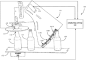
- FIG. 1 illustrates an exemplary container inspection system.
- FIG. 2 illustrates another exemplary container inspection system.
- FIG. 3 illustrates an image gathered by an image capture system of an exemplary container inspection system.
- FIG. 4 illustrates a further exemplary container inspection system.
- FIG. 5 illustrates a yet further exemplary container inspection system.
- FIG. 6 illustrates yet another exemplary container inspection system.
- FIG. 7 illustrates another exemplary container inspection system.
- FIG. 8 illustrates a further exemplary container inspection system.
- FIG. 9 illustrates a yet further exemplary image capture system.
- FIG. 10 illustrates yet another exemplary container inspection system.
- FIG. 11 illustrates depicts a functional block diagram of a computing system of a container inspection system.
- FIG. 12 is a flow diagram that illustrates an exemplary methodology for forming a container inspection system.
- FIG. 13 is an exemplary computing device.
- the term “or” is intended to mean an inclusive “or” rather than an exclusive “or.” That is, unless specified otherwise, or clear from the context, the phrase “X employs A or B” is intended to mean any of the natural inclusive permutations. That is, the phrase “X employs A or B” is satisfied by any of the following instances: X employs A; X employs B; or X employs both A and B.
- the articles “a” and “an” as used in this application and the appended claims should generally be construed to mean “one or more” unless specified otherwise or clear from the context to be directed to a singular form.
- the term “exemplary” is intended to mean serving as an illustration or example of something and is not intended to indicate a preference.
- an apparatus for inspecting a glass container for flaws in a body of the glass container e.g., for flaws in a finish of a glass bottle.
- conventional approaches for detecting checks tend to be time-consuming and mechanically complex. They involve a human picking up a glass container and visually inspecting for a crack or an automated inspection system rotating the glass container and directing collimated light towards specific positions on the glass container and capturing images of those specific positions while collimated light is directed towards such positions. Manually removing a glass container for visual inspection or rotating the glass container slows the conveyor line down because each glass container must be manipulated.
- the embodiments described herein can be performed without requiring a glass container to be rotated during inspection because diffuse light is emitted to symmetrically illuminate the glass container about a central axis of the glass container, resulting in even illumination of the glass container.
- the even illumination allows for images to be gathered from multiple sides of the glass container simultaneously without requiring rotation of the glass container, light source, and/or image capture device and thus, without requiring the conveyor line to be slowed down for manual manipulation of the glass containers.
- FIG. 1 illustrated is an exemplary embodiment of a container inspection system 100 configured to illuminate a glass container and to inspect the illuminated glass container.
- a conveyor 102 transports a plurality of glass containers 104 - 106 through the container inspection system 100 .
- the container inspection system 100 comprises an illuminator 108 configured to emit light to illuminate the plurality of glass containers 104 - 106 as they travel through the container inspection system 100 .
- the container inspection system 100 also comprises an image capture system 110 configured to capture one or more images of each of the plurality of glass containers 104 - 106 as the plurality of glass containers 104 - 106 are transported through the container inspection system 100 by the conveyor 102 .
- the image capture system 110 can be configured to capture the image(s) during illumination of each container by the illuminator 108 , as will be described in detail below.
- the illuminator 108 can take any suitable shape and/or comprise any suitable components for providing light to illuminate each of the plurality of glass containers 104 - 106 as the plurality of glass containers 104 - 106 are transported through the container inspection system 100 by the conveyor 102 .
- the illuminator 108 can include a light source(s) configured to emit light at specified times such as when a container is directly beneath the illuminator 108 . Any suitable light source may be employed and the light source may be selected based on any number of characteristics, such as type of container being inspected, type of defect to be detected, desired type of emitted light, and/or the like.
- the illuminator 108 can include an electroluminescence light source such as a light emitting diode (LED).
- the containers 104 - 106 are formed of a transparent or semi-transparent material (such as glass) and the light from the illuminator 108 passes through a sidewall(s) of a container as the container is beneath the illuminator 108 to illuminate the container.
- the illuminator 108 can include any suitable number of light sources and the number may depend on the desired type of light or any other suitable factor.
- the illuminator 108 can include a plurality of LEDs organized in a particular arrangement. Each LED can be configured to emit a similar light or the light can vary. It is to be understood, however, that other types of light source are contemplated.
- the illuminator 108 may further include a device and/or structure that alters the light emitted from the light source.
- the illuminator 108 may optionally include a lens or plurality of lenses that focuses light from the light source toward a specific portion(s) of the container and/or a diffusing element that diffuses light.
- the illuminator 108 may include a diffuser that diffuses or scatters light from the light source to evenly illuminate a glass container (e.g., the first container 104 ). Diffusing the light from the light source may result in symmetric illumination of a portion of the glass container about a central axis of the container.
- a diffuser that diffuses or scatters light from the light source to evenly illuminate a glass container (e.g., the first container 104 ). Diffusing the light from the light source may result in symmetric illumination of a portion of the glass container about a central axis of the container.
- collimated or focused light is aimed at a specific point on the glass container while an image is captured of that point. Because the light is directed toward a specific point on the container in conventional systems, either the container or the light source needs to be rotated in order to capture illuminated images for the whole bottle.
- using a diffuser permits for rotationally symmetric illumination of the container, thereby avoiding the need to rotate the container.
- the illuminator 108 may be configured to illuminate any suitable portion of a container that is beneath the illuminator 108 (e.g., the first container 104 ).
- the container may be a bottle and the illuminator 108 may be configured to illuminate a portion of the finish of the bottle (i.e., the upper portion of the bottle).
- the illuminator 108 may be configured to illuminate the entire container.
- the illuminator 108 may be configured to emit light for any suitable period of time.
- the illuminator 108 may be configured to emit light when a container is directly beneath the illuminator 108 .
- the illuminator 108 can be strobed, such that the aforementioned container surface is illuminated for a relatively short amount of time (e.g., on the order of tens of microseconds) when the container is detected as being directly beneath the illuminator 108 .
- the image capture system 110 is configured to capture at least one image of each of the plurality of containers 104 - 106 as the containers 104 - 106 are transported through the container inspection system 100 by the conveyor 102 .
- the image capture system 110 may be configured to capture the image(s) of a container (e.g., the first container 104 ) when the container is directly beneath the illuminator 108 .
- the image capture system 110 can be configured to capture the image(s) of the container when the container is illuminated by the illuminator 108 .
- the image capture system 110 can include any suitable number of image capture instruments that are each configured to capture any suitable number of images of the plurality of containers 104 - 106 .
- the image capture system 110 may comprise one and only one image capture instrument that captures an image that includes several views of a container.
- the image capture system 110 may comprise a plurality of image capture instruments that each (simultaneously) capture a different image of a container, with each image including a different view of the container.
- the image capture system 110 can be configured to capture the image(s) for each of the plurality of containers 104 - 106 during their illumination by the illuminator 108 .
- an image of a container (e.g., the first container 104 ) captured by the image capture system 110 can include several views of the container.
- the number of views captured in an image is dependent upon a number of mirrors included in the image capture system 110 .
- the image capture system 110 can take any suitable shape and comprise any suitable structure(s) for generating an image that includes multiple views of the container.
- the image capture system 110 may comprise a camera or several cameras.
- the image capture system 110 may comprise a mirror or several mirrors that are positioned to capture view(s) of a container while the container is being illuminated.
- the image capture system 110 includes a plurality of different mirrors.
- the image capture system 110 includes a mirror that is arranged between the illuminator 108 and a container (e.g., the first container 104 ) on the conveyor 102 .
- the mirror can take any suitable shape and/or size for reflecting a portion of the container thereon.
- the mirror may have a cross-section that is circular, rectangular, triangular, ovular, or the like.
- the mirror comprises an annular mirror 112 .
- the annular mirror 112 includes an aperture 114 extending therethrough permitting light from the illuminator 108 to reach a container that is directly beneath the illuminator 108 .
- the aperture 114 can have any suitable cross-section for permitting light from the illuminator 108 to pass through to illuminate the container.
- the aperture 114 has a circular cross-section with a diameter smaller than a diameter of an open end of the container facing the annular mirror 112 .
- the annular mirror 112 can be configured to be reflective on every surface or only a portion thereof.
- the surface of annular mirror 112 facing downward toward the container is reflective such that portion(s) of the container are reflected in the annular mirror 112 when a point of view is beneath the annular mirror 112 .
- the surface of the annular mirror 112 that reflects the container can take any suitable shape; and in the example depicted in FIGS. 1 and 2 the surface is planar and is substantially perpendicular to an open end of the container. This reflection of the container by the annular mirror 112 can be seen more clearly in FIG. 2 .
- the image capture system 110 may further include an additional reflective surface that is arranged to simultaneously reflect a portion of the container and a portion of the annular mirror 112 .
- the additional reflective surface can take any suitable shape and size for reflecting the container and the annular mirror 112 .
- the additional reflective surface may be rectangular, triangular, ovular, circular, or the like; and, moreover, may be planar, oscillating, or the like.
- illustrated in FIG. 1 is a rectangular, planar additional reflective surface 116 A.
- the image capture system 110 can include any number of additional reflective surfaces. Each of the additional reflective surfaces can be similar in shape and size or can vary. For instance, in the embodiment illustrated in FIG. 1 , the image capture system 110 includes four additional reflective surfaces 116 A-D that are each rectangular and planar.
- Each of the four additional reflective surfaces 116 A-D can be arranged at a suitable location for simultaneously reflecting a view of the container being inspected (e.g., the first container 104 ) and a view of the reflection of the container from the annular mirror 112 .
- Each of the four additional reflective surfaces 116 A-D can be arranged to reflect a different view of the container and/or a different view of the reflection of the container from the annular mirror 112 .
- a first additional reflective surface 116 A can be arranged at a first position relative to the annular mirror 112 while a second additional reflective surface 116 B can be arranged at a different second position relative to the annular mirror 112 .
- the four additional reflective surfaces 116 A-D are arranged along a curved path.
- the image capture system 110 may further include a camera 118 configured to capture an image of one or more of the additional reflective surfaces while the container 104 is being illuminated by the illuminator 108 .
- the camera 118 can be placed at any suitable location and can include any suitable structure to capture the image of the one or more additional reflective surfaces 116 A- 116 D.
- the image capture system 110 can include any suitable number of cameras to capture images of the additional reflective surfaces 116 A- 116 D while the container is being illuminated by the illuminator 108 . For instance, a first camera can be positioned to capture an image of a first additional reflective surface and a second camera can be positioned to capture an image of a second additional reflective surface.
- the camera 118 is configured to capture an image of each of the four additional reflective surfaces 116 A-D while the container is being illuminated by the illuminator 108 and is directly beneath the illuminator 108 .
- the camera 118 can be placed such that each additional reflective surface 116 A- 116 D is the same focal distance from the camera 118 .
- the container inspection system 100 can further comprise a sensor 120 that outputs a signal that is indicative of when a container (e.g., the first container 104 ) has reached an inspection region directly underneath the illuminator 108 .
- the image capture system 110 is configured to capture an image(s) of the first container 104 when the first container 104 is in the inspection region.
- Any suitable sensor 120 for detecting when the container has reached the inspection region may be employed.
- the sensor 120 may be a presence sensor that can detect when the first container 104 has reached a particular point (e.g., when the first container 104 is directly underneath the illuminator 108 ).
- the senor 120 may be a rotary sensor that is configured to output data based upon movement of the conveyor 102 .
- the output data therefore, is indicative of a position of the first container 104 relative to a previous position of the first container 104 on the conveyor 102 and, thus, the position of the first container 104 relative to the inspection region.
- the container inspection system 100 may further comprise a computing system 122 that receives the signal output by the sensor 120 .
- the computing system 122 can receive the signal from the sensor 120 by way of a wireless or wireline connection.
- the computing system 122 may further receive information from and/or transmit information to the illuminator 108 and/or the image capture system 110 .
- the computing system 122 may transmit a signal to the illuminator 108 to cause the illuminator 108 to emit light.
- the signal sent to the illuminator 108 may be sent responsive to the computing system 122 receiving the signal output by the sensor 120 indicating a container, such as the first container 104 , is directly underneath the illuminator 108 .
- the computing system 122 can be configured to transmit a signal to the illuminator 108 that causes the illuminator 108 to strobe light each time a container is detected as being directly beneath the illuminator 108 .
- the computing system 122 may transmit an image request signal to the camera 118 to cause the camera 118 to capture the image(s) of a container in the inspection region.
- the computing system 122 can be configured to transmit the image request signal responsive to receiving the signal output by the sensor 120 , simultaneously with the signal transmitted to the illuminator 108 discussed above, after the signal is transmitted to the illuminator 108 , and/or any other suitable time.
- the computing system 122 may be configured to substantially simultaneously send a signal to the illuminator 108 and a signal to the camera 118 such that when light from the illuminator 108 is emitted to illuminate the container, the camera 118 simultaneously captures the image(s) of the illuminated container.
- the computing system 122 may be further configured to receive data from the camera 118 such as one or more images generated by the camera 118 . The computing system 122 can then determine whether the container includes a defect (e.g., a check) based upon the image(s) of the illuminated container.
- a defect e.g., a check
- the image 300 includes eight views of a container: four reflections of the container in the additional reflective surfaces 116 A-D, respectively, and four double-reflections of the container (reflections of the container in the annular mirror 112 that are again reflected in the additional reflective surfaces 116 A-D, respectively).
- the camera 118 captures the image 300 when the image capture system 110 includes the four additional reflective surfaces 116 A-D described above.
- the image 300 includes four sections each including two views: a view of the container as (directly) reflected from an additional reflective surface and a view of the container as reflected from the annular mirror which is then reflected from the additional reflective surface.
- a first section 302 includes a first view of the container 310 and a first view of the annular mirror reflecting the container 312 as reflected from the fourth additional reflective surface 116 D.
- a second section 304 includes a second view of the container 314 and a second view of the annular mirror reflecting the container 316 as reflected from the third additional reflective surface 116 C.
- a third section 306 includes a third view of the container 318 and a third view of the annular mirror reflecting the container 320 as reflected from the second additional reflective surface 116 B.
- a fourth section 308 includes a fourth view of the container 322 and a fourth view of the annular mirror reflecting the container 324 as reflected from the first additional reflective surface 116 A.
- the image 300 can be received by the computing system 122 and the computing system 122 can then determine whether the finish of the container includes a defect based upon the image 300 .
- the computing system 122 may align the image 300 with a statistical model of a defect-free container.
- the statistical model can include expected values of pixels of images at portions of the container as well as an expected distribution of such values, such that the image 300 can be aligned with different portions of the statistical model and a determination can be made as to whether the glass container includes the defect.
- templates also referred to as signatures
- signatures for defects that are desirably identified can be employed to detect defects in glass containers.
- a template may represent a shape of a defect that is to be identified, and the image 300 can be searched for such shape. Responsive to detecting a defect in the inspected container, the computing system 122 can be configured to output a signal indicative of such detection.
- the inspected container includes a defect 326 .
- the defect 326 in the illustrated embodiment, comprises a check or crack in the finish of the container. A portion of this defect 326 can be seen in each of the first section 302 , the second section 304 , the third section 306 , and the fourth section 308 . More particularly, the portion of the defect 326 can be seen in the double-reflections of the container (reflections of the container in the annular mirror 112 that are again reflected in the additional reflective surfaces 116 A-D).
- the image capture system 400 includes an annular mirror 402 (similar to the annular mirror 112 described above) configured to reflect a container being inspected, such as the first container 104 .
- the illustrated image capture system 400 employs a plurality of cameras 404 A-D that function similar to the additional reflective surfaces described above. More particularly, each camera in the plurality of cameras 404 A-D is configured to capture an image comprising a view of the container being inspected and a view of the annular mirror 402 reflecting the container.
- the plurality of cameras 404 A-D can be arranged at any suitable position(s) for collecting the images. In the illustrated embodiment, the plurality of cameras 404 A-D are arranged along an arced path.
- the computing system 122 can be configured to receive images generated from the plurality of cameras 404 A-D. The computing system 122 can then identify a defect in one or more containers based upon the received images. In one embodiment, templates for a defect can be developed, and the computing system can compare the templates with content of the images to identify defects in glass containers.
- the image capture system 500 comprises a plurality of reflective surfaces 502 A-H that are arranged to reflect a portion of a container being inspected (e.g., the first container 104 ) at different views and a camera 504 arranged to capture an image comprising the reflections from the plurality of reflective surfaces 502 A-H.
- the plurality of reflective surfaces 502 A-H can be arranged in any suitable pattern for reflecting views of the container.
- the plurality of reflective surfaces 502 A-H are arranged along an arced path with a first portion below an open end of the container and a second portion above the open end of the container.
- the camera 504 can be arranged such that the plurality of mirrors 502 A-H are the same focal distance from the camera 504 .
- the computing system 122 can be configured to receive the image from the camera 504 and detect a defect in a glass container based upon the image, as described above.
- the image capture system 600 comprises a plurality of cameras 602 A-F that are each configured to capture images of a portion of a container being inspected (e.g., the first container 104 ) at different views.
- Each camera of the plurality of cameras 602 A-F can be configured to capture an image comprising a view of the inspected container.
- the plurality of cameras 602 A-F can be arranged in any suitable pattern to capture an image of the portion of the inspected container. In the embodiment of FIG.
- the plurality of cameras 602 A-F are arranged in an arced path with a portion of the plurality of cameras 602 A-F arranged below an open end of the container and a second portion of the plurality of the cameras 602 A-F arranged above the open end of the container.
- the computing system 122 can be configured to receive images generated by the plurality of cameras 602 A-F. The computing system 122 can then detect a defect in the glass container based upon the images output by the plurality of cameras 602 A-F.
- the reflective surfaces and/or cameras are arranged along a first side of the container to capture an image(s) along the first side of the container.
- the illuminator 108 emits diffuse light
- the container being inspected is evenly illuminated and an additional image capture system can be used to obtain an image(s) of a second side of the container without requiring rotation of the container.
- the above described container inspection system 100 can be employed to inspect different sides of the container without touching the container to rotate it.
- the container inspection system 100 can include any suitable number of additional image capture systems.
- the plurality of image capture systems can be similar to each other and/or they can vary.
- the number of additional image capture systems can be based on any suitable factor, such as size of the container, shape of the container, the amount of container being inspected, or the like.
- the container inspection system 100 can include two image capture systems.
- the container inspection system 100 can include six image capture systems.
- the container inspection system 100 can include eight image capture systems.
- the additional image capture systems can be located at any suitable location, as will be described in detail below.
- Illustrated in FIG. 7 is one embodiment of a container inspection system 700 that includes a first image capture system 702 (similar to the image capture system 110 described above) and a second image capture system 704 .
- the first image capture system 702 is located on a first side of a container being inspected (e.g., the first container 104 ) and the second image capture system 704 is located on a second side of the container opposite the first side.
- the container inspection system 700 includes an annular mirror 706 that is utilized by both the first image capture system 702 and the second image capture system 704 to capture multiple views of the container.
- the first image capture system 702 can include four reflective surfaces 708 A-D each arranged to reflect an image comprising a view of the container and a view of the container reflected by the annular mirror 706 .
- the first image capture system 702 further includes a camera 710 that captures an image of the reflections from the four reflective surfaces 708 A-D.
- the second image capture system 704 can include four reflective surfaces 712 A-D each arranged to reflect an image comprising a view of the container and a view of the container reflected by the annular mirror 706 .
- the second image capture system 704 can further include a camera 714 that captures an image of the reflections from the four reflective surfaces 712 A-D.
- the computing system 122 can be configured to receive the images from the first image capture system 702 and the second image capture system 704 and detect defects in the glass container based upon such images.
- FIG. 8 illustrated is another embodiment of a container inspection system 800 that includes a first image capture system 802 and a second image capture system 804 .
- the first image capture system 802 is located at a first inspection region along a conveyor path of the container and the second image capture system 804 is located at a second inspection region along the conveyor path of the container.
- the first inspection region and the second inspection region can each include a separate illuminator 806 and 808 , respectively.
- the first inspection region and/or the second inspection region may each include a sensor (similar to the sensor 120 described above) that indicates when a container is in the first inspection region and/or second inspection region.
- the first inspection region includes a first sensor 810 and the second inspection region includes a second sensor 812 .
- the first sensor 810 and/or the second sensor 812 can be configured to output a signal indicative of a location of a container (e.g., the first container 104 ) with respect to the first inspection region and/or the second inspection region.
- the first image capture system 802 and the second image capture system 804 can be similar or can vary.
- the first image capture system 802 and the second image capture system 804 are similar with each including an annular mirror (similar to the annular mirror 108 described above) to reflect a view of the container.
- the first image capture system 802 and the second image capture system 804 can further comprise a plurality of additional reflective surfaces that are arranged to reflect a view of the container and a view of the reflection of the container by the annular mirror simultaneously and a camera arranged to capture an image comprising the reflections from the plurality of additional reflective surfaces.
- the first image capture system 802 can be configured to capture an image of a first side of the container while the second image capture system 804 can be configured to capture an image of a second side of the container.
- the computing system 122 can be configured to receive the images generated by the cameras of the first image capture system 802 and the second image capture system 804 .
- the computing system 122 can be configured to detect a defect in a container based upon the images generated by the cameras.
- FIG. 9 illustrated is a further image capture system 900 that includes a plurality of arrangements to generate images for 360° inspection of a container via a single illuminator without requiring rotation of the container. Any suitable number and/or type of arrangements may be used to generate the images, such as six arrangements, eight arrangements, etc.
- the image capture system 900 includes six arrangements 902 A-F equally spaced around an inspection region for a container (e.g., the first container 104 ).
- the image capture system 900 further includes an annular mirror 904 (similar to the annular mirror 112 described above) that reflects a view of the container thereon.
- annular mirror 904 similar to the annular mirror 112 described above
- FIG. 9 it is conceivable that separate mirrors can be used for one or more of the plurality of arrangements 902 A-F.
- Each of the arrangements 902 A-F include a plurality of planar mirrors (similar to the additional reflective surfaces 116 A-D described above); each configured to reflect a view of the container and a view of the reflection of the container by the annular mirror 904 simultaneously.
- Each of the plurality of arrangements 902 A-F can further include a camera configured to capture an image comprising the respective reflections from the plurality of planar mirrors. Accordingly, by organizing the plurality of arrangements 902 A-F in the illustrated pattern, the image capture system 900 provides for a 360° inspection of the container via a singular illuminator without requiring rotation of the container.
- the illustrated organization of the plurality of arrangements 902 A-F allows for a singular annular mirror 904 positioned above the container to be employed to generate multiple views of the container in each image captured by each camera.
- the computing system 122 can be configured to receive the images generated by the cameras of the image capture system 900 .
- the computing system 122 can be configured to detect a defect in a container based upon the images generated by the cameras.
- FIG. 10 illustrated is another container inspection system 1000 that comprises an illuminator 1002 (similar to the above described illuminator 108 ), an image capture system 1004 , and a rotation mechanism 1006 .
- the rotation mechanism 1006 can be employed to rotate the container while the image capture system 1004 captures views for any desired number of sides of the container (e.g., two sides, four sides, or the like). Any suitable image capture system 1004 can be employed for capturing the views of the side of the container, such as the image capture systems described above.
- the computing system 122 includes a processor 1100 and memory 1102 .
- the memory 1102 has images 1104 (generated by the image capture system(s) of the container inspection system 100 ) loaded therein.
- the images 1104 can comprise: 1) an image capture by a first image capture system; and 2) an image captured by a second image capture system, where the images can be captured when the container is illuminated by way of diffuse light emitted from the illuminator.
- the memory 1102 has one or more templates 1106 , wherein the templates 1106 correspond to defects that are to be detected by the container inspection system 100 .
- the templates 1106 can include mathematical representations of defects that can be found in a glass container (e.g., a vertical check, a horizontal check, etc.), and the computing system 122 can search images for portions thereof that correspond to such defects.
- the memory 1102 further includes a defect detection application 1108 loaded therein.
- the defect detection application 1108 may be configured to ascertain whether the container has a defect therein based upon the images 1104 and the templates 1106 . More particularly, the defect detection application 1108 may be configured to perform template matching by comparing a template against an image by moving the template around the image to calculate a numerical measure of similarity between the template and the portion of the image it overlaps. For instance, the defect detection application 1108 can use a template image of a defect to scan an image for the defect based on the numerical measure. The defect detection application 1108 can be further configured to output a signal indicating that the inspected container is defective.
- FIG. 12 illustrates an exemplary methodology 1200 relating to forming a container inspection system. While the methodology is shown as being a series of acts that are performed in a sequence, it is to be understood and appreciated that the methodology is not limited by the order of the sequence. For example, some acts can occur in a different order than what is described herein. In addition, an act can occur concurrently with another act. Further, in some instances, not all acts may be required to implement a methodology described herein.
- the methodology 1200 starts at 1202 , and at 1204 , a diffuse illuminator is arranged to illuminate a portion of a glass container with diffused light.
- a first mirror is arranged relative to a conveyor that is configured to transport glass containers such that when the portion of the glass container is illuminated with the diffuse light, a first reflection of the portion of the glass container is observable in the first mirror when the first mirror is viewed from a first position.
- a second mirror is arranged at the first position such that when the portion of the glass container is illuminated with the diffuse light, and when the second mirror is viewed from a second position, the first reflection of the portion of the glass container in the first mirror is observable in the second mirror and a second reflection of the portion of the glass container is also observable in the second mirror.
- a camera is placed at the second position. The camera can be configured to capture an image of the second mirror when the glass container is illuminated with the diffuse light such that the image captures the first reflection and the second reflection of the portion of the glass container.
- the methodology 1200 concludes at 1212 .
- the first mirror is a planar mirror comprising an aperture.
- Arranging the first mirror may comprise placing the first mirror between the illuminator and the conveyor.
- a reflective surface of the planar mirror can be arranged to face toward the conveyor.
- the first mirror may be arranged relative to the illuminator such that diffuse light emitted by the illuminator passes through the aperture towards the conveyor.
- the first mirror is arranged such that when the portion of the glass container is illuminated with the diffuse light, a third reflection of the portion of the glass container is observable in the first mirror when the first mirror is viewed from a third position that is different from the first position.
- the methodology 1200 can further include arranging a third mirror at the third position such that when the portion of the glass container is illuminated with the diffuse light, and when the third mirror is viewed from the second position, the third reflection of the portion of the glass container in the first mirror is observable in the third mirror and a fourth reflection of the portion of the glass container is also observable in the third mirror.
- the image generated by the camera may capture the third mirror when the glass container is illuminated with the diffuse light such that the image captures the third reflection and the fourth reflection of the portion of the glass container.
- the first mirror is arranged such that when the portion of the glass container is illuminated with the diffuse light, a fifth reflection of the portion of the glass container is observable in the first mirror when the first mirror is viewed from a fourth position that is different from the first position and the third position.
- the methodology 1200 can further comprise arranging a fourth mirror at the fourth position such that when the portion of the glass container is illuminated with the diffuse light, and when the fourth mirror is viewed from the second position, the fifth reflection of the portion of the glass container in the first mirror is observable in the fourth mirror and a sixth reflection of the portion of the glass container is also observable in the fourth mirror.
- the image generated by the camera can also capture the fourth mirror when the glass container is illuminated with the diffuse light such that the image captures the fifth reflection and the sixth reflection of the portion of the glass container.
- the centers of the second mirror, the third mirror, and the fourth mirror are equidistant to the camera.
- the computing device 1300 may be or include a mobile computing device or the computing system.
- the computing device 1300 includes at least one processor 1302 that executes instructions that are stored in a memory 1304 .
- the instructions may be, for instance, instructions for implementing functionality described as being carried out by one or more components discussed above or instructions for implementing one or more methods described above.
- the processor 1302 may be a GPU, a plurality of GPUs, a CPU, a plurality of CPUs, a multi-core processor, etc.
- the processor 1302 may access the memory 1304 by way of a system bus 1306 .
- the memory 1304 may also store images, defect signatures, etc.
- the computing device 1300 additionally includes a data store 1310 that is accessible by the processor 1302 by way of the system bus 1306 .
- the data store 1310 may include executable instructions, images, statistical models, etc.
- the computing device 1300 also includes an input interface 1308 that allows external devices to communicate with the computing device 1300 .
- the input interface 1308 may be used to receive instructions from an external computer device, from a user, etc.
- the computing device 1300 also includes an output interface 1312 that interfaces the computing device 1300 with one or more external devices.
- the computing device 1300 may display text, images, etc. by way of the output interface 1312 .
- the external devices that communicate with the computing device 1300 via the input interface 1308 and the output interface 1312 can be included in an environment that provides substantially any type of user interface with which a user can interact.
- user interface types include graphical user interfaces, natural user interfaces, and so forth.
- a graphical user interface may accept input from a user employing input device(s) such as a keyboard, mouse, remote control, or the like and provide output on an output device such as a display.
- a natural user interface may enable a user to interact with the computing device 1300 in a manner free from constraints imposed by input devices such as keyboards, mice, remote controls, and the like. Rather, a natural user interface can rely on speech recognition, touch and stylus recognition, gesture recognition both on screen and adjacent to the screen, air gestures, head and eye tracking, voice and speech, vision, touch, gestures, machine intelligence, and so forth.
- the computing device 1300 may be a distributed system. Thus, for instance, several devices may be in communication by way of a network connection and may collectively perform tasks described as being performed by the computing device 1300 .
- Computer-readable media includes computer-readable storage media.
- a computer-readable storage media can be any available storage media that can be accessed by a computer.
- such computer-readable storage media can comprise RAM, ROM, EEPROM, CD-ROM or other optical disk storage, magnetic disk storage or other magnetic storage devices, or any other medium that can be used to store desired program code in the form of instructions or data structures and that can be accessed by a computer.
- Disk and disc include compact disc (CD), laser disc, optical disc, digital versatile disc (DVD), floppy disk, and Blu-ray disc (BD), where disks usually reproduce data magnetically and discs usually reproduce data optically with lasers. Further, a propagated signal is not included within the scope of computer-readable storage media.
- Computer-readable media also includes communication media including any medium that facilitates transfer of a computer program from one place to another. A connection, for instance, can be a communication medium.
- the software is transmitted from a website, server, or other remote source using a coaxial cable, fiber optic cable, twisted pair, digital subscriber line (DSL), or wireless technologies such as infrared, radio, and microwave
- coaxial cable, fiber optic cable, twisted pair, DSL, or wireless technologies such as infrared, radio, and microwave are included in the definition of communication medium.
- DSL digital subscriber line
- wireless technologies such as infrared, radio, and microwave
- the functionally described herein can be performed, at least in part, by one or more hardware logic components.
- illustrative types of hardware logic components include Field-programmable Gate Arrays (FPGAs), Application-specific Integrated Circuits (ASICs), Application-specific Standard Products (ASSPs), System-on-a-chip systems (SOCs), Complex Programmable Logic Devices (CPLDs), etc.
Landscapes
- Physics & Mathematics (AREA)
- Engineering & Computer Science (AREA)
- General Physics & Mathematics (AREA)
- Signal Processing (AREA)
- Multimedia (AREA)
- Immunology (AREA)
- Health & Medical Sciences (AREA)
- Life Sciences & Earth Sciences (AREA)
- Chemical & Material Sciences (AREA)
- Analytical Chemistry (AREA)
- Biochemistry (AREA)
- General Health & Medical Sciences (AREA)
- Pathology (AREA)
- Optics & Photonics (AREA)
- Computer Vision & Pattern Recognition (AREA)
- Quality & Reliability (AREA)
- Theoretical Computer Science (AREA)
- Investigating Materials By The Use Of Optical Means Adapted For Particular Applications (AREA)
Priority Applications (7)
| Application Number | Priority Date | Filing Date | Title |
|---|---|---|---|
| US17/110,277 US11047803B1 (en) | 2020-09-10 | 2020-12-02 | Glass container inspection system |
| EP21867302.8A EP4211449A4 (en) | 2020-09-10 | 2021-06-28 | GLASS CONTAINER INSPECTION SYSTEM |
| KR1020237011804A KR20230106151A (ko) | 2020-09-10 | 2021-06-28 | 유리 용기 검사 시스템 |
| PCT/US2021/039463 WO2022055596A1 (en) | 2020-09-10 | 2021-06-28 | Glass container inspection system |
| JP2023516498A JP7676538B2 (ja) | 2020-09-10 | 2021-06-28 | ガラス容器検査システム |
| CN202180071559.1A CN116888458A (zh) | 2020-09-10 | 2021-06-28 | 玻璃容器检查系统 |
| MX2023002918A MX2023002918A (es) | 2020-09-10 | 2021-06-28 | Sistema de inspeccion de recipientes de vidrio. |
Applications Claiming Priority (2)
| Application Number | Priority Date | Filing Date | Title |
|---|---|---|---|
| US202063076763P | 2020-09-10 | 2020-09-10 | |
| US17/110,277 US11047803B1 (en) | 2020-09-10 | 2020-12-02 | Glass container inspection system |
Publications (1)
| Publication Number | Publication Date |
|---|---|
| US11047803B1 true US11047803B1 (en) | 2021-06-29 |
Family
ID=76548344
Family Applications (1)
| Application Number | Title | Priority Date | Filing Date |
|---|---|---|---|
| US17/110,277 Active US11047803B1 (en) | 2020-09-10 | 2020-12-02 | Glass container inspection system |
Country Status (7)
Cited By (2)
| Publication number | Priority date | Publication date | Assignee | Title |
|---|---|---|---|---|
| US20240098353A1 (en) * | 2022-09-19 | 2024-03-21 | Applied Vision Corporation | Glass container inspection system |
| CN119985515A (zh) * | 2025-04-16 | 2025-05-13 | 潍坊天恒检测科技有限公司 | 一种不旋转玻璃瓶裂纹检测设备及其检测方法 |
Families Citing this family (1)
| Publication number | Priority date | Publication date | Assignee | Title |
|---|---|---|---|---|
| WO2022103262A1 (en) * | 2020-11-11 | 2022-05-19 | Centrum Voor Technische Informatica B.V. | Method for inspecting hollow glass products of glass product material |
Citations (22)
| Publication number | Priority date | Publication date | Assignee | Title |
|---|---|---|---|---|
| US3942001A (en) * | 1973-06-27 | 1976-03-02 | Talcoma Teoranta | Inspection of containers |
| DE4022733C1 (en) * | 1989-12-19 | 1991-05-08 | Elpatronic Ag, Zug, Ch | Three=dimensional cavity inspection appts. - uses matrix or line camera to receive reflected light via gp. of four mirrors and deflecting mirror |
| US5495330A (en) * | 1994-09-16 | 1996-02-27 | Emhart Glass Machinery Investments Inc. | Container inspection machine having sequentially accessed computer alignment gages |
| US5661294A (en) * | 1993-12-06 | 1997-08-26 | Elpatronic Ag | Process and apparatus for the optical inspection of a transparent region of a container, in particular the mouth region |
| US5699152A (en) * | 1995-04-03 | 1997-12-16 | Alltrista Corporation | Electro-optical inspection system and method |
| US5729340A (en) * | 1993-07-30 | 1998-03-17 | Krones Ag Hermann Kronseder Maschinenfabrik | Bottle inspection machine |
| GB2318635A (en) * | 1996-10-24 | 1998-04-29 | Mitsubishi Nuclear Fuel | Container interion imaging system |
| US6104482A (en) | 1999-12-02 | 2000-08-15 | Owens-Brockway Glass Container Inc. | Container finish check detection |
| US6512239B1 (en) | 2000-06-27 | 2003-01-28 | Photon Dynamics Canada Inc. | Stereo vision inspection system for transparent media |
| US6654116B1 (en) * | 1999-08-25 | 2003-11-25 | Krones Ag Hermann Kronseder | Device and method of optical inspection of open beverage containers |
| US20040134843A1 (en) | 2001-03-07 | 2004-07-15 | Kolb Frank Rainer | Waste water installation with purification device |
| US6795176B1 (en) * | 2003-06-30 | 2004-09-21 | Emhart Glass S.A. | Container inspection machine |
| US20040263620A1 (en) * | 2003-06-30 | 2004-12-30 | Diehr Richard D. | Container inspection machine |
| US20060126060A1 (en) * | 2002-10-25 | 2006-06-15 | Olivier Colle | Lighting method and device for detection of surface defects and/or unfilled finish on the finish of a container |
| US20080095427A1 (en) | 2006-10-23 | 2008-04-24 | Novini Amir R | Machine for inspecting glass containers |
| US20110007149A1 (en) | 2006-10-23 | 2011-01-13 | Diehr Richard D | Machine For Inspecting Glass Containers At An Inspection Station Using An Addition Of A Plurality Of Illuminations Of Reflected Light |
| US20160077020A1 (en) * | 2013-05-03 | 2016-03-17 | Mic & Sgcc | Method and device for observing and analysing optical singularities in glass containers |
| US9322787B1 (en) | 2014-10-18 | 2016-04-26 | Emhart Glass S.A. | Glass container inspection machine with a graphic user interface |
| US20180143143A1 (en) * | 2015-05-08 | 2018-05-24 | Industrial Dynamics Company Ltd. | System and method for inspecting bottles and containers using light |
| US10012598B2 (en) | 2015-07-17 | 2018-07-03 | Emhart S.A. | Multi-wavelength laser check detection tool |
| US20190204238A1 (en) * | 2016-07-06 | 2019-07-04 | Tiama | Process, device and line of inspection for determination of a wire-edge at the site of an internal edge of a ring surface |
| US20200333259A1 (en) * | 2018-01-05 | 2020-10-22 | Tiama | Method, device and inspection line for determining the three-dimensional geometry of a container ring surface |
Family Cites Families (6)
| Publication number | Priority date | Publication date | Assignee | Title |
|---|---|---|---|---|
| US4424441A (en) * | 1981-06-12 | 1984-01-03 | Owens-Illinois, Inc. | Method and apparatus for inspecting glass containers |
| JP4361156B2 (ja) * | 1999-02-22 | 2009-11-11 | 三菱重工食品包装機械株式会社 | 物品の外観検査装置 |
| JP2005134358A (ja) * | 2003-10-28 | 2005-05-26 | Yoshihiko Takashima | 4枚の傾斜ミラーの使用により、カメラ1台で平面と4方向側面を撮像する方式 |
| WO2012172695A1 (ja) * | 2011-06-15 | 2012-12-20 | キリンテクノシステム株式会社 | ガラス壜の検査方法および装置 |
| JP5883779B2 (ja) * | 2012-05-29 | 2016-03-15 | 株式会社 日立産業制御ソリューションズ | 撮像装置および照明装置 |
| PL229618B1 (pl) * | 2016-05-10 | 2018-08-31 | Ksm Vision Spolka Z Ograniczona Odpowiedzialnoscia | Urządzenie do kontroli powierzchni zewnętrznych i geometrii obiektów na liniach produkcyjnych z wykorzystaniem obserwacji kołowej w pełnym zakresie obwodowym 360° |
-
2020
- 2020-12-02 US US17/110,277 patent/US11047803B1/en active Active
-
2021
- 2021-06-28 CN CN202180071559.1A patent/CN116888458A/zh active Pending
- 2021-06-28 JP JP2023516498A patent/JP7676538B2/ja active Active
- 2021-06-28 WO PCT/US2021/039463 patent/WO2022055596A1/en active Application Filing
- 2021-06-28 EP EP21867302.8A patent/EP4211449A4/en active Pending
- 2021-06-28 MX MX2023002918A patent/MX2023002918A/es unknown
- 2021-06-28 KR KR1020237011804A patent/KR20230106151A/ko active Pending
Patent Citations (22)
| Publication number | Priority date | Publication date | Assignee | Title |
|---|---|---|---|---|
| US3942001A (en) * | 1973-06-27 | 1976-03-02 | Talcoma Teoranta | Inspection of containers |
| DE4022733C1 (en) * | 1989-12-19 | 1991-05-08 | Elpatronic Ag, Zug, Ch | Three=dimensional cavity inspection appts. - uses matrix or line camera to receive reflected light via gp. of four mirrors and deflecting mirror |
| US5729340A (en) * | 1993-07-30 | 1998-03-17 | Krones Ag Hermann Kronseder Maschinenfabrik | Bottle inspection machine |
| US5661294A (en) * | 1993-12-06 | 1997-08-26 | Elpatronic Ag | Process and apparatus for the optical inspection of a transparent region of a container, in particular the mouth region |
| US5495330A (en) * | 1994-09-16 | 1996-02-27 | Emhart Glass Machinery Investments Inc. | Container inspection machine having sequentially accessed computer alignment gages |
| US5699152A (en) * | 1995-04-03 | 1997-12-16 | Alltrista Corporation | Electro-optical inspection system and method |
| GB2318635A (en) * | 1996-10-24 | 1998-04-29 | Mitsubishi Nuclear Fuel | Container interion imaging system |
| US6654116B1 (en) * | 1999-08-25 | 2003-11-25 | Krones Ag Hermann Kronseder | Device and method of optical inspection of open beverage containers |
| US6104482A (en) | 1999-12-02 | 2000-08-15 | Owens-Brockway Glass Container Inc. | Container finish check detection |
| US6512239B1 (en) | 2000-06-27 | 2003-01-28 | Photon Dynamics Canada Inc. | Stereo vision inspection system for transparent media |
| US20040134843A1 (en) | 2001-03-07 | 2004-07-15 | Kolb Frank Rainer | Waste water installation with purification device |
| US20060126060A1 (en) * | 2002-10-25 | 2006-06-15 | Olivier Colle | Lighting method and device for detection of surface defects and/or unfilled finish on the finish of a container |
| US6795176B1 (en) * | 2003-06-30 | 2004-09-21 | Emhart Glass S.A. | Container inspection machine |
| US20040263620A1 (en) * | 2003-06-30 | 2004-12-30 | Diehr Richard D. | Container inspection machine |
| US20080095427A1 (en) | 2006-10-23 | 2008-04-24 | Novini Amir R | Machine for inspecting glass containers |
| US20110007149A1 (en) | 2006-10-23 | 2011-01-13 | Diehr Richard D | Machine For Inspecting Glass Containers At An Inspection Station Using An Addition Of A Plurality Of Illuminations Of Reflected Light |
| US20160077020A1 (en) * | 2013-05-03 | 2016-03-17 | Mic & Sgcc | Method and device for observing and analysing optical singularities in glass containers |
| US9322787B1 (en) | 2014-10-18 | 2016-04-26 | Emhart Glass S.A. | Glass container inspection machine with a graphic user interface |
| US20180143143A1 (en) * | 2015-05-08 | 2018-05-24 | Industrial Dynamics Company Ltd. | System and method for inspecting bottles and containers using light |
| US10012598B2 (en) | 2015-07-17 | 2018-07-03 | Emhart S.A. | Multi-wavelength laser check detection tool |
| US20190204238A1 (en) * | 2016-07-06 | 2019-07-04 | Tiama | Process, device and line of inspection for determination of a wire-edge at the site of an internal edge of a ring surface |
| US20200333259A1 (en) * | 2018-01-05 | 2020-10-22 | Tiama | Method, device and inspection line for determining the three-dimensional geometry of a container ring surface |
Cited By (2)
| Publication number | Priority date | Publication date | Assignee | Title |
|---|---|---|---|---|
| US20240098353A1 (en) * | 2022-09-19 | 2024-03-21 | Applied Vision Corporation | Glass container inspection system |
| CN119985515A (zh) * | 2025-04-16 | 2025-05-13 | 潍坊天恒检测科技有限公司 | 一种不旋转玻璃瓶裂纹检测设备及其检测方法 |
Also Published As
| Publication number | Publication date |
|---|---|
| JP2023542865A (ja) | 2023-10-12 |
| EP4211449A1 (en) | 2023-07-19 |
| KR20230106151A (ko) | 2023-07-12 |
| WO2022055596A1 (en) | 2022-03-17 |
| EP4211449A4 (en) | 2024-10-23 |
| CN116888458A (zh) | 2023-10-13 |
| JP7676538B2 (ja) | 2025-05-14 |
| MX2023002918A (es) | 2023-07-26 |
Similar Documents
| Publication | Publication Date | Title |
|---|---|---|
| US11047803B1 (en) | Glass container inspection system | |
| EP1779096B1 (en) | Apparatus and method for checking of containers | |
| US9377416B2 (en) | Wafer edge detection and inspection | |
| US20210178431A1 (en) | Sequential imaging for container sidewall inspection | |
| CN104897693A (zh) | 一种玻璃表面缺陷增强装置及其检测方法 | |
| US11836912B2 (en) | Grading cosmetic appearance of a test object based on multi-region determination of cosmetic defects | |
| US10393670B1 (en) | Container inspection system | |
| CN113196043A (zh) | 用于药物产品容器中的微粒检测的片状照明 | |
| US20180059006A1 (en) | Systems, apparatus, and related methods for evaluating biological sample integrity | |
| CN106052792A (zh) | 一种基于机器视觉的pet瓶液位检测方法及装置 | |
| JP4876201B1 (ja) | ガラスびん検査装置及びテレセントリックレンズユニット | |
| CN107923837A (zh) | 用于使用多个辐射源来检查容器的系统和方法 | |
| US20200378899A1 (en) | Glass processing apparatus and methods | |
| WO2019214287A1 (zh) | 检测装置及其检测方法、检测设备 | |
| US5126556A (en) | Bottle thread imaging apparatus having a light seal means between the light assembly means and the thread | |
| JP2000241363A (ja) | 物品の外観検査装置及び外観検査方法 | |
| CN118974548A (zh) | 宝石的表面分析 | |
| US20200300781A1 (en) | Inspecting method, inspection system, and manufacturing method | |
| US9243893B2 (en) | Optoelectronic method and appliance for measuring the inside diameter of a hollow body | |
| US20240098353A1 (en) | Glass container inspection system | |
| JPH10242227A (ja) | ウエハのマクロ検査方法および自動ウエハマクロ検査装置 | |
| JP2006258778A (ja) | 表面欠陥検査方法および表面欠陥検査装置 | |
| RU69634U1 (ru) | Прибор для обнаружения и классификации дефектов оптических объектов (варианты) | |
| WO2020199206A1 (zh) | 透明或半透明材料微观缺陷检测系统及方法 | |
| US20250232429A1 (en) | Systems and methods for visual inspection of pharmaceutical containers |
Legal Events
| Date | Code | Title | Description |
|---|---|---|---|
| FEPP | Fee payment procedure |
Free format text: ENTITY STATUS SET TO UNDISCOUNTED (ORIGINAL EVENT CODE: BIG.); ENTITY STATUS OF PATENT OWNER: LARGE ENTITY |
|
| FEPP | Fee payment procedure |
Free format text: ENTITY STATUS SET TO SMALL (ORIGINAL EVENT CODE: SMAL); ENTITY STATUS OF PATENT OWNER: LARGE ENTITY |
|
| FEPP | Fee payment procedure |
Free format text: ENTITY STATUS SET TO UNDISCOUNTED (ORIGINAL EVENT CODE: BIG.); ENTITY STATUS OF PATENT OWNER: LARGE ENTITY |
|
| STCF | Information on status: patent grant |
Free format text: PATENTED CASE |
|
| MAFP | Maintenance fee payment |
Free format text: PAYMENT OF MAINTENANCE FEE, 4TH YEAR, LARGE ENTITY (ORIGINAL EVENT CODE: M1551); ENTITY STATUS OF PATENT OWNER: LARGE ENTITY Year of fee payment: 4 |