US10972707B2 - Endoscope and method of manufacturing endoscope - Google Patents
Endoscope and method of manufacturing endoscope Download PDFInfo
- Publication number
- US10972707B2 US10972707B2 US16/517,138 US201916517138A US10972707B2 US 10972707 B2 US10972707 B2 US 10972707B2 US 201916517138 A US201916517138 A US 201916517138A US 10972707 B2 US10972707 B2 US 10972707B2
- Authority
- US
- United States
- Prior art keywords
- main surface
- light emitting
- region
- upper plate
- optical
- Prior art date
- Legal status (The legal status is an assumption and is not a legal conclusion. Google has not performed a legal analysis and makes no representation as to the accuracy of the status listed.)
- Active, expires
Links
- 238000004519 manufacturing process Methods 0.000 title claims description 8
- 230000003287 optical effect Effects 0.000 claims abstract description 142
- 239000013307 optical fiber Substances 0.000 claims abstract description 44
- 239000011347 resin Substances 0.000 claims abstract description 35
- 229920005989 resin Polymers 0.000 claims abstract description 35
- 238000003780 insertion Methods 0.000 claims description 31
- 230000037431 insertion Effects 0.000 claims description 31
- 238000005452 bending Methods 0.000 claims description 24
- 238000000034 method Methods 0.000 claims description 16
- 102220475086 Bifunctional arginine demethylase and lysyl-hydroxylase JMJD6_L90A_mutation Human genes 0.000 description 7
- 239000002184 metal Substances 0.000 description 6
- 230000000694 effects Effects 0.000 description 4
- 239000000835 fiber Substances 0.000 description 4
- 238000005286 illumination Methods 0.000 description 4
- 230000008054 signal transmission Effects 0.000 description 3
- 239000004593 Epoxy Substances 0.000 description 2
- NIXOWILDQLNWCW-UHFFFAOYSA-N acrylic acid group Chemical group C(C=C)(=O)O NIXOWILDQLNWCW-UHFFFAOYSA-N 0.000 description 2
- 239000000853 adhesive Substances 0.000 description 2
- 230000001070 adhesive effect Effects 0.000 description 2
- 239000000919 ceramic Substances 0.000 description 2
- 238000012986 modification Methods 0.000 description 2
- 230000004048 modification Effects 0.000 description 2
- VGGSQFUCUMXWEO-UHFFFAOYSA-N Ethene Chemical compound C=C VGGSQFUCUMXWEO-UHFFFAOYSA-N 0.000 description 1
- JOYRKODLDBILNP-UHFFFAOYSA-N Ethyl urethane Chemical compound CCOC(N)=O JOYRKODLDBILNP-UHFFFAOYSA-N 0.000 description 1
- 239000005977 Ethylene Substances 0.000 description 1
- YCKRFDGAMUMZLT-UHFFFAOYSA-N Fluorine atom Chemical compound [F] YCKRFDGAMUMZLT-UHFFFAOYSA-N 0.000 description 1
- 239000005062 Polybutadiene Substances 0.000 description 1
- 239000003990 capacitor Substances 0.000 description 1
- 239000004020 conductor Substances 0.000 description 1
- 229910052731 fluorine Inorganic materials 0.000 description 1
- 239000011737 fluorine Substances 0.000 description 1
- 239000011521 glass Substances 0.000 description 1
- 238000010438 heat treatment Methods 0.000 description 1
- 238000001727 in vivo Methods 0.000 description 1
- 238000007689 inspection Methods 0.000 description 1
- 239000007788 liquid Substances 0.000 description 1
- 239000000463 material Substances 0.000 description 1
- 239000000615 nonconductor Substances 0.000 description 1
- 230000002093 peripheral effect Effects 0.000 description 1
- 229920002647 polyamide Polymers 0.000 description 1
- 229920002857 polybutadiene Polymers 0.000 description 1
- 229920000515 polycarbonate Polymers 0.000 description 1
- 239000004417 polycarbonate Substances 0.000 description 1
- 229920001296 polysiloxane Polymers 0.000 description 1
- 239000000523 sample Substances 0.000 description 1
- 229910052710 silicon Inorganic materials 0.000 description 1
- 239000010703 silicon Substances 0.000 description 1
- 239000000758 substrate Substances 0.000 description 1
- 239000012780 transparent material Substances 0.000 description 1
- 125000000391 vinyl group Chemical group [H]C([*])=C([H])[H] 0.000 description 1
- 229920002554 vinyl polymer Polymers 0.000 description 1
- XLYOFNOQVPJJNP-UHFFFAOYSA-N water Substances O XLYOFNOQVPJJNP-UHFFFAOYSA-N 0.000 description 1
Images


Classifications
-
- H—ELECTRICITY
- H04—ELECTRIC COMMUNICATION TECHNIQUE
- H04N—PICTORIAL COMMUNICATION, e.g. TELEVISION
- H04N7/00—Television systems
- H04N7/22—Adaptations for optical transmission
-
- A—HUMAN NECESSITIES
- A61—MEDICAL OR VETERINARY SCIENCE; HYGIENE
- A61B—DIAGNOSIS; SURGERY; IDENTIFICATION
- A61B1/00—Instruments for performing medical examinations of the interior of cavities or tubes of the body by visual or photographical inspection, e.g. endoscopes; Illuminating arrangements therefor
- A61B1/00002—Operational features of endoscopes
- A61B1/00011—Operational features of endoscopes characterised by signal transmission
- A61B1/00013—Operational features of endoscopes characterised by signal transmission using optical means
-
- A—HUMAN NECESSITIES
- A61—MEDICAL OR VETERINARY SCIENCE; HYGIENE
- A61B—DIAGNOSIS; SURGERY; IDENTIFICATION
- A61B1/00—Instruments for performing medical examinations of the interior of cavities or tubes of the body by visual or photographical inspection, e.g. endoscopes; Illuminating arrangements therefor
- A61B1/00064—Constructional details of the endoscope body
- A61B1/00071—Insertion part of the endoscope body
- A61B1/0008—Insertion part of the endoscope body characterised by distal tip features
- A61B1/00096—Optical elements
-
- A—HUMAN NECESSITIES
- A61—MEDICAL OR VETERINARY SCIENCE; HYGIENE
- A61B—DIAGNOSIS; SURGERY; IDENTIFICATION
- A61B1/00—Instruments for performing medical examinations of the interior of cavities or tubes of the body by visual or photographical inspection, e.g. endoscopes; Illuminating arrangements therefor
- A61B1/00064—Constructional details of the endoscope body
- A61B1/0011—Manufacturing of endoscope parts
-
- A—HUMAN NECESSITIES
- A61—MEDICAL OR VETERINARY SCIENCE; HYGIENE
- A61B—DIAGNOSIS; SURGERY; IDENTIFICATION
- A61B1/00—Instruments for performing medical examinations of the interior of cavities or tubes of the body by visual or photographical inspection, e.g. endoscopes; Illuminating arrangements therefor
- A61B1/00112—Connection or coupling means
- A61B1/00121—Connectors, fasteners and adapters, e.g. on the endoscope handle
- A61B1/00124—Connectors, fasteners and adapters, e.g. on the endoscope handle electrical, e.g. electrical plug-and-socket connection
-
- A—HUMAN NECESSITIES
- A61—MEDICAL OR VETERINARY SCIENCE; HYGIENE
- A61B—DIAGNOSIS; SURGERY; IDENTIFICATION
- A61B1/00—Instruments for performing medical examinations of the interior of cavities or tubes of the body by visual or photographical inspection, e.g. endoscopes; Illuminating arrangements therefor
- A61B1/00163—Optical arrangements
- A61B1/00165—Optical arrangements with light-conductive means, e.g. fibre optics
-
- A—HUMAN NECESSITIES
- A61—MEDICAL OR VETERINARY SCIENCE; HYGIENE
- A61B—DIAGNOSIS; SURGERY; IDENTIFICATION
- A61B1/00—Instruments for performing medical examinations of the interior of cavities or tubes of the body by visual or photographical inspection, e.g. endoscopes; Illuminating arrangements therefor
- A61B1/005—Flexible endoscopes
- A61B1/009—Flexible endoscopes with bending or curvature detection of the insertion part
-
- A—HUMAN NECESSITIES
- A61—MEDICAL OR VETERINARY SCIENCE; HYGIENE
- A61B—DIAGNOSIS; SURGERY; IDENTIFICATION
- A61B1/00—Instruments for performing medical examinations of the interior of cavities or tubes of the body by visual or photographical inspection, e.g. endoscopes; Illuminating arrangements therefor
- A61B1/04—Instruments for performing medical examinations of the interior of cavities or tubes of the body by visual or photographical inspection, e.g. endoscopes; Illuminating arrangements therefor combined with photographic or television appliances
- A61B1/045—Control thereof
-
- A—HUMAN NECESSITIES
- A61—MEDICAL OR VETERINARY SCIENCE; HYGIENE
- A61B—DIAGNOSIS; SURGERY; IDENTIFICATION
- A61B1/00—Instruments for performing medical examinations of the interior of cavities or tubes of the body by visual or photographical inspection, e.g. endoscopes; Illuminating arrangements therefor
- A61B1/04—Instruments for performing medical examinations of the interior of cavities or tubes of the body by visual or photographical inspection, e.g. endoscopes; Illuminating arrangements therefor combined with photographic or television appliances
- A61B1/05—Instruments for performing medical examinations of the interior of cavities or tubes of the body by visual or photographical inspection, e.g. endoscopes; Illuminating arrangements therefor combined with photographic or television appliances characterised by the image sensor, e.g. camera, being in the distal end portion
- A61B1/051—Details of CCD assembly
-
- G—PHYSICS
- G02—OPTICS
- G02B—OPTICAL ELEMENTS, SYSTEMS OR APPARATUS
- G02B23/00—Telescopes, e.g. binoculars; Periscopes; Instruments for viewing the inside of hollow bodies; Viewfinders; Optical aiming or sighting devices
- G02B23/24—Instruments or systems for viewing the inside of hollow bodies, e.g. fibrescopes
- G02B23/2407—Optical details
- G02B23/2446—Optical details of the image relay
-
- G—PHYSICS
- G02—OPTICS
- G02B—OPTICAL ELEMENTS, SYSTEMS OR APPARATUS
- G02B23/00—Telescopes, e.g. binoculars; Periscopes; Instruments for viewing the inside of hollow bodies; Viewfinders; Optical aiming or sighting devices
- G02B23/24—Instruments or systems for viewing the inside of hollow bodies, e.g. fibrescopes
- G02B23/2407—Optical details
- G02B23/2461—Illumination
- G02B23/2469—Illumination using optical fibres
-
- G—PHYSICS
- G02—OPTICS
- G02B—OPTICAL ELEMENTS, SYSTEMS OR APPARATUS
- G02B23/00—Telescopes, e.g. binoculars; Periscopes; Instruments for viewing the inside of hollow bodies; Viewfinders; Optical aiming or sighting devices
- G02B23/24—Instruments or systems for viewing the inside of hollow bodies, e.g. fibrescopes
- G02B23/2476—Non-optical details, e.g. housings, mountings, supports
- G02B23/2484—Arrangements in relation to a camera or imaging device
-
- G—PHYSICS
- G02—OPTICS
- G02B—OPTICAL ELEMENTS, SYSTEMS OR APPARATUS
- G02B6/00—Light guides; Structural details of arrangements comprising light guides and other optical elements, e.g. couplings
- G02B6/24—Coupling light guides
- G02B6/42—Coupling light guides with opto-electronic elements
- G02B6/4201—Packages, e.g. shape, construction, internal or external details
- G02B6/4204—Packages, e.g. shape, construction, internal or external details the coupling comprising intermediate optical elements, e.g. lenses, holograms
- G02B6/4212—Packages, e.g. shape, construction, internal or external details the coupling comprising intermediate optical elements, e.g. lenses, holograms the intermediate optical element being a coupling medium interposed therebetween, e.g. epoxy resin, refractive index matching material, index grease, matching liquid or gel
-
- G—PHYSICS
- G02—OPTICS
- G02B—OPTICAL ELEMENTS, SYSTEMS OR APPARATUS
- G02B6/00—Light guides; Structural details of arrangements comprising light guides and other optical elements, e.g. couplings
- G02B6/24—Coupling light guides
- G02B6/42—Coupling light guides with opto-electronic elements
- G02B6/4201—Packages, e.g. shape, construction, internal or external details
- G02B6/4219—Mechanical fixtures for holding or positioning the elements relative to each other in the couplings; Alignment methods for the elements, e.g. measuring or observing methods especially used therefor
- G02B6/4236—Fixing or mounting methods of the aligned elements
- G02B6/424—Mounting of the optical light guide
- G02B6/4242—Mounting of the optical light guide to the lid of the package
-
- H—ELECTRICITY
- H04—ELECTRIC COMMUNICATION TECHNIQUE
- H04N—PICTORIAL COMMUNICATION, e.g. TELEVISION
- H04N23/00—Cameras or camera modules comprising electronic image sensors; Control thereof
- H04N23/50—Constructional details
- H04N23/54—Mounting of pick-up tubes, electronic image sensors, deviation or focusing coils
-
- H—ELECTRICITY
- H04—ELECTRIC COMMUNICATION TECHNIQUE
- H04N—PICTORIAL COMMUNICATION, e.g. TELEVISION
- H04N23/00—Cameras or camera modules comprising electronic image sensors; Control thereof
- H04N23/50—Constructional details
- H04N23/55—Optical parts specially adapted for electronic image sensors; Mounting thereof
-
- H—ELECTRICITY
- H04—ELECTRIC COMMUNICATION TECHNIQUE
- H04N—PICTORIAL COMMUNICATION, e.g. TELEVISION
- H04N23/00—Cameras or camera modules comprising electronic image sensors; Control thereof
- H04N23/50—Constructional details
- H04N23/555—Constructional details for picking-up images in sites, inaccessible due to their dimensions or hazardous conditions, e.g. endoscopes or borescopes
-
- H—ELECTRICITY
- H04—ELECTRIC COMMUNICATION TECHNIQUE
- H04N—PICTORIAL COMMUNICATION, e.g. TELEVISION
- H04N23/00—Cameras or camera modules comprising electronic image sensors; Control thereof
- H04N23/56—Cameras or camera modules comprising electronic image sensors; Control thereof provided with illuminating means
-
- H04N5/2253—
-
- H04N5/2254—
-
- H04N5/2256—
-
- H—ELECTRICITY
- H04—ELECTRIC COMMUNICATION TECHNIQUE
- H04N—PICTORIAL COMMUNICATION, e.g. TELEVISION
- H04N7/00—Television systems
- H04N7/18—Closed-circuit television [CCTV] systems, i.e. systems in which the video signal is not broadcast
- H04N7/183—Closed-circuit television [CCTV] systems, i.e. systems in which the video signal is not broadcast for receiving images from a single remote source
Definitions
- the present invention relates to an endoscope including an optical module, in which a bonding wire is bonded to an external electrode in an optical element, disposed in a distal end section, and a method for manufacturing the endoscope.
- An endoscope includes an image pickup device such as a CMOS image sensor or a CCD in a distal end section in an elongated insertion section.
- an image pickup device having a large number of pixels has been considered to display a high-quality image.
- an amount of an image signal to be transmitted to a signal processor from the image pickup device increases. Accordingly, in electric signal transmission via a metal wiring by an electric signal, a wire diameter of the metal wiring needs to be increased to transmit a required signal amount, so that the insertion section may be thick due to the wiring.
- optical signal transmission via a thin optical fiber by an optical signal instead of the electric signal is preferable.
- an E/O-type optical module electrical/optical converter
- an O/E-type optical module optical/electrical converter
- Japanese Patent Application Laid-Open Publication No. 2013-025092 discloses an optical module including an optical element, a substrate on which the optical element is mounted, and a holding section (ferrule) having a through hole into which an optical fiber configured to transmit an optical signal to be inputted into or outputted from the optical element is inserted.
- Japanese Patent Application Laid-Open Publication No. 2015-97589 discloses an endoscope in which no stress is applied to an optical fiber even if a bending section is deformed because the optical fiber is inserted through a center of the bending section.
- Japanese Patent Application Laid-Open Publication No. 2001-281503 discloses an optical module in which multiple reflection is prevented by arranging an optical element in an inclined manner at a predetermined inclination angle to a bottom surface of a ferrule as a supporting member in the optical fiber.
- a convex-shaped angle holding member is disposed in the optical element only to arrange the optical element in an inclined manner.
- Japanese Patent Application Laid-Open Publication No. 2010-219166 discloses an opening portion or a notch portion into which a bonding wire protrudes is formed in a wavelength converting member disposed on an optical element.
- An endoscope is an endoscope including an image pickup device configured to shoot an object and output an image pickup signal and an optical module configured to convert the image pickup signal into an optical signal and transmit the optical signal using an optical fiber in a distal end section in an insertion section, in which the optical module includes a light emitting element which includes a light emitting surface for outputting the optical signal and a rear surface, an external electrode being disposed, out of a first region and a second region obtained by dividing the light emitting surface substantially in half, only in the first region, a wiring board which includes a first main surface and a second main surface, the light emitting element and a bonding electrode being disposed on the first main surface, a bonding wire which connects the external electrode and the bonding electrode to each other, a ferrule which includes an insertion hole, the optical fiber being inserted into the insertion hole, a frame which includes an upper plate and a side plate, the ferrule being disposed on the upper plate and the side plate being fixed to the first
- a method for manufacturing an endoscope is a method in which a light emitting element which includes a light emitting surface for outputting an optical signal and a rear surface opposing the light emitting surface, an external electrode being disposed, out of a first region and a second region obtained by dividing the light emitting surface substantially in half, only in the first region is disposed, in a wiring board including a first main surface and a second main surface, on the first main surface on which a bonding electrode is disposed, the external electrode and the bonding electrode are connected to each other with a bonding wire, a frame which includes an upper plate and a side plate, includes a side surface including an opening, and is inclined to the first main surface is disposed on the first main surface in the wiring board such that a first distance from the first main surface to the first region is longer than a second distance from the first main surface to the second region and the light emitting element is housed in an inner section, a ferrule is disposed on the upper plate, an optical fiber configured to
- FIG. 1 is a perspective view of an endoscope system including an endoscope according to a first embodiment
- FIG. 2 is a plan view of a distal end section in the endoscope according to the first embodiment
- FIG. 3 is a cross-sectional view along a line III-III illustrated in FIG. 2 of the distal end section in the endoscope according to the first embodiment;
- FIG. 4 is an exploded view of an optical module in the endoscope according to the first embodiment
- FIG. 5 is a cross-sectional view of the optical module in the endoscope according to the first embodiment
- FIG. 6 is a side view of the optical module in the endoscope according to the first embodiment
- FIG. 7 is a top view of the optical module in the endoscope according to the first embodiment
- FIG. 8A is a perspective view of a holding frame in the optical module in the endoscope according to the first embodiment
- FIG. 8B is a perspective view of the holding frame in the optical module in the endoscope according to the first embodiment
- FIG. 8C is a perspective view of the holding frame in the optical module in the endoscope according to the first embodiment
- FIG. 8D is a perspective view of the holding frame in the optical module in the endoscope according to the first embodiment
- FIG. 9 is a flowchart for describing a method for manufacturing the optical module in the endoscope according to the first embodiment
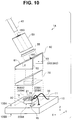
- FIG. 10 is an exploded view of an optical module in an endoscope according to a second embodiment
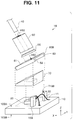
- FIG. 11 is an exploded view of an optical module in an endoscope according to a third embodiment
- FIG. 12 is an exploded view of an optical module in an endoscope according to a fourth embodiment
- FIG. 13 is an exploded view of an optical module in an endoscope according to a fifth embodiment.
- FIG. 14 is a cross-sectional view of an optical module in an endoscope according to a sixth embodiment.
- An endoscope system 8 including an endoscope 9 according to the present embodiment illustrated in FIG. 1 includes the endoscope 9 , a processor 80 , a light source device 81 , and a monitor 82 .
- the endoscope 9 shoots an in-vivo image of a subject and outputs an image pickup signal with an insertion section 90 circular in cross section inserted into a body cavity of the subject.
- drawings based on each of embodiments are schematic and a relationship between a thickness and a width of each of sections and a ratio of the thicknesses of the sections respectively differ from actual ones, and sections which differ in dimensional relationship or ratio may also be included among the drawings. Illustration of some of components and assignment of reference numerals may be omitted.
- An operation section 91 provided with various types of buttons configured to operate the endoscope 9 is disposed in a proximal end portion of the insertion section 90 in the endoscope 9 .
- the operation section 91 has a treatment instrument insertion opening in a channel 94 (see FIG. 2 ) configured to insert living body forceps, electrocautery, an inspection probe, and the like into the body cavity of the subject.
- the insertion section 90 includes a rigid distal end section 90 A, a bendable bending section 90 B consecutively connected to the distal end section 90 A, and a flexible section 90 C consecutively connected to the bending section 90 B.
- the bending section 90 B is bent by an operation of the operation section 91 .
- a universal code 92 extending from the operation section 91 is connected to the processor 80 and the light source device 81 via a connector 93 .
- a signal cable 40 M configured to transmit an electric signal to be outputted by an O/E-type optical module 1 X is inserted through the universal code 92 .
- the optical module 1 X may be arranged in the connector 93 in the universal code 92 , for example.
- the processor 80 controls the entire endoscope system 8 while performing signal processing for an image pickup signal to be outputted by an image pickup apparatus 3 (see FIG. 3 ) and outputting the image pickup signal as an image signal.
- the monitor 82 displays the image signal to be outputted by the processor 80 .
- the light source device 81 includes a white LED, for example. Illumination light to be emitted by the light source device 81 is guided to an illumination optical system 96 (see FIG. 2 ) in the distal end section 90 A via a light guide (not illustrated) configured to be inserted through the universal code 92 and the insertion section 90 , to illuminate an object.
- the image pickup apparatus 3 including an E/O-type optical module 1 is disposed in the distal end section 90 A.
- an electric signal is converted into an optical signal by the optical module 1 in the rigid distal end section 90 A, and is transmitted to the operation section 91 via a thin optical fiber 40 configured to be inserted through the insertion section 90 .
- the optical signal is converted again into an electric signal by the O/E-type optical module 1 X disposed in the operation section 91 , and is transmitted to an electrical connector 93 via a signal cable 40 M as a metal wiring configured to be inserted through the universal code 92 .
- the image pickup signal is transmitted via the optical fiber 40 within the insertion section 90 having a small diameter, and is transmitted via the signal cable 40 M as a thicker metal wiring than the optical fiber 40 within the universal code 92 which is not inserted into a body and an outer diameter of which is hardly restricted.
- the optical module 1 X is arranged in the connector 93 or the processor 80 , the optical fiber 40 is inserted through the universal code 92 .
- FIG. 2 is a front view of the distal end section 90 A in the endoscope 9 as viewed in a distal end direction.
- the distal end section 90 A includes a cylindrical housing 4 , which is tubular in its rear, an outer peripheral surface of which is covered with an outer skin 5 made of a resin.
- the housing 4 has a plurality of through holes parallel to a distal end section central axis C 1 of the distal end section 90 A.
- An observation window of the image pickup optical system 2 A and an opening of the channel 94 are disposed on a distal end surface such that the distal end section central axis C 1 (a central axis C of the insertion section 90 ) is interposed therebetween.
- an optical axis O of the image pickup optical system 2 A inserted into the through hole of the housing 4 is parallel to the distal end section central axis C 1 (C) and is eccentric.
- Respective illumination windows of the two illumination optical systems 96 and a nozzle 97 for air feeding/water feeding are further disposed on the distal end surface.
- FIG. 3 illustrates a plane (YZ plane) including the optical axis O of the image pickup optical system 2 A and the distal end section central axis C, as indicated by a line illustrated in FIG. 2 .
- the image pickup apparatus 3 including the image pickup optical system 2 A, an image pickup device 2 B, and the optical module 1 is housed in the through hole of the housing 4 in the distal end section 90 A having a length L 90 A.
- the image pickup device 2 B configured to shoot an object and output an image pickup signal is a CMOS image sensor or a CCD.
- the image pickup signal is converted into an optical signal in the optical module 1 ,
- the optical fiber 40 in the optical module 1 includes a core having a diameter of 50 ⁇ m configured to transmit light and a clad having a diameter of 125 ⁇ m which covers an outer periphery of the core, for example.
- the optical fiber 40 extends toward the distal end section central axis C 1 , and is arranged along a bending section central axis C 2 of the bending section 90 B.
- guide members 99 for arranging the optical fiber 40 along the distal end section central axis C 1 are disposed in a proximal end portion of the distal end section 90 A and the bending section 90 B. Details of the guide members 99 are disclosed in Japanese Patent Application Laid-Open Publication No. 2015-97589 already described.
- the guide members 99 are also preferably disposed in the flexible section 90 C, which are not illustrated. Note that the flexible section 90 C is not greatly deformed compared to the bending section 90 B. Therefore, an arrangement spacing between the guide members 99 in the flexible section 90 C may be longer than an arrangement spacing in the bending section 90 B.
- One multi-lumen tube having substantially the same outer diameter as an inner diameter of the bending section 90 B and inserted through the bending section 90 B may be used as the guide member.
- the optical fiber 40 can be arranged along the bending section central axis C 2 .
- the optical fiber 40 receives a large stress particularly when the insertion section 90 is deformed by a bending operation of the bending section 90 B.
- the optical fiber 40 is arranged along the bending section central axis C 2 . Therefore, even if the bending section 90 B is deformed, the optical fiber 40 does not receive a great stress. Accordingly, the endoscope 9 is high in reliability because a loss may hardly occur in a video signal to be transmitted by the optical fiber 40 .
- the optical fiber 40 is arranged such that a fiber distal end section is inclined by an angle ⁇ , e.g., 45° ⁇ 10°, i.e., not less than 35 degrees and not more than 55 degrees to the distal end section central axis C 1 in a cross section (the YZ plane) including the central axis C and the optical axis O and extends in a direction toward the distal end section central axis C 1 .
- ⁇ e.g., 45° ⁇ 10°
- the endoscope 9 including the image pickup device 2 B having a large number of pixels transmits an image signal via the optical fiber 40 . Therefore, the endoscope 9 is minimally invasive and can display a high-quality image.
- the optical fiber 40 can be arranged along the bending section central axis C 2 without being greatly bent. Therefore, the endoscope 9 is high in reliability. Further, the optical fiber 40 can be arranged along the bending section central axis C 2 in a short distance. Therefore, the endoscope 9 is minimally invasive because the length L 90 A of the distal end section 90 A is small.
- optical module 1 in the endoscope 9 Details of the optical module 1 in the endoscope 9 will be described below with reference to FIGS. 4 to 8A .
- the optical module 1 includes a wiring board 10 , an optical element 20 , a bonding wire 30 , a ferrule 50 , a holding frame 60 , and a transparent resin 70 .
- the wiring board 10 includes a first main surface 10 SA and a second main surface 10 SB opposing the first main surface 10 SA.
- the optical element 20 and a bonding electrode 11 are disposed on the first main surface 10 SA in the wiring board 10 .
- a driving signal is transmitted to the bonding electrode 11 via a wiring not illustrated.
- the image pickup device 2 B is mounted on the second main surface 10 SB in the wiring board 10 in the optical module 1 . Accordingly, the first main surface 10 SA and the second main surface 10 SB are perpendicular to the optical axis O of the image pickup device 2 B.
- Electronic components such as a driving IC and a chip capacitor for driving the optical element 20 may be mounted on the wiring board 10 .
- the optical element 20 includes a light emitting surface 20 SA for outputting an optical signal and a rear surface 20 SB opposing the light emitting surface 20 SA.
- the optical element 20 is a surface light emitting laser chip including a light emitting section 21 configured to output light of the optical signal.
- a micro optical element 20 having planar-view dimensions (a size in a direction perpendicular to the optical axis) of 250 ⁇ m ⁇ 300 ⁇ m and having a thickness of 150 ⁇ m includes a light emitting section 21 having a diameter of 20 ⁇ m and an external electrode 22 configured to feed a driving signal to the light emitting section 21 on a light emitting surface 20 SA.
- two external electrodes 22 are disposed, out of a first region 20 SA 1 and a second region 20 SA 2 obtained by dividing the light emitting surface 20 SA substantially in half, only in the first region 20 SA 1 .
- the first region 20 SA 1 and the second region 20 SA 2 need not be accurately two halves such that their respective areas are completely equal to each other, but may be respectively separated as different regions.
- the bonding wire 30 connects the external electrode 22 in the optical element 20 and the bonding electrode 11 in the wiring board 10 to each other.
- the bonding wire 30 is a metal wire having a diameter of 30 ⁇ m, for example.
- the bonding wire 30 protrudes by approximately 100 ⁇ m from the light emitting surface 20 SA.
- the holding frame 60 includes an upper plate 61 and a plurality of side plates 62 , 63 , and 64 .
- the side plates 62 , 63 , and 64 are fixed to the first main surface 10 SA in the wiring board 10 .
- An inner section S 60 in the holding frame 60 has a space formed by the upper plate 61 and the side plates 62 , 63 , and 64 .
- the side surface having a largest area opposing the side plate 64 is an opening O 60 .
- the optical element 20 disposed on the wiring board 10 is housed in the inner section S 60 in the holding frame 60 .
- the upper plate 61 in the holding frame 60 is inclined at a predetermined inclination angle ⁇ to the first main surface 10 SA in the wiring board 10 .
- the upper plate 61 is inclined such that a first distance d 1 from the first main surface 10 SA to the first region 20 SA 1 is longer than a second distance d 2 from the first main surface 10 SA to the second region 20 SA 2 .
- the bonding wire 30 protrudes by approximately 100 ⁇ m from the light emitting surface 20 SA.
- the upper plate 61 is inclined. Therefore, the bonding wire 30 does not contact the upper plate 61 . Accordingly, even if the upper plate 61 is a conductor, conduction do not occur between the two bonding wires 30 .
- the bonding wire 30 is deformed upon being pressed by the upper plate 61 so that no stress is applied to a bonding section. Accordingly, bonding reliability is ensured in the optical module 1 .
- the bonding wire 30 contacts the upper plate 61 but is not greatly deformed, bonding reliability may be ensured in the optical module 1 .
- the bonding wire 30 does not preferably contact the upper plate 61 .
- a length from the first main surface 10 SA in the wiring board 10 to an upper surface of the ferrule 50 in the optical module 1 is smaller than a length in an optical module in which an upper plate 61 is not inclined. In other words, a length in an optical axis direction of the optical module 1 is small. Therefore, the endoscope 9 is minimally invasive because a length of the rigid distal end section 90 A is small.
- the transparent resin 70 is disposed in the inner section S 60 in the holding frame 60 .
- the transparent resin 70 is a refractive index matching material having substantially the same refractive index as a refractive index of the core in the optical fiber 40 .
- the transparent resin 70 include an acrylic-based resin, an epoxy-based resin, a vinyl-based resin, an ethylene-based resin, a silicone-based resin, a urethane-based resin, a polyamide-based resin, a fluorine-based resin, a polybutadiene-based resin, and a polycarbonate-based resin.
- the acrylic-based resin and the epoxy-based resin are appropriate for the transparent resin 70 from a viewpoint of moisture resistance, heat resistance, detachment resistance, and impact resistance.
- the holding frame 60 includes side plates 62 , 63 , and 64 , a surface, opposing the side plate 64 , of the holding frame 60 does not include a side plate but is an opening O 60 .
- the transparent resin 70 is injected in a liquid state into the inner section S 60 from the opening O 60 after the holding frame 60 is fixed to the wiring board 10 , and is solidified by curing treatment, e.g., heating or ultraviolet irradiation.
- the ferrule 50 is fixed to the upper plate 61 in the holding frame 60 using an adhesive 55 .
- the ferrule 50 is made of glass, a metal member, ceramic, or silicon.
- An inner wall shape of an insertion hole H 50 in the ferrule 50 may be prismatic in addition to being columnar if the optical fiber 40 can be held in a wall surface of the insertion hole H 50 .
- a fiber distal end portion of the optical fiber 40 is inserted into the insertion hole 50 H in the ferrule 50 , and is optically coupled to the optical element 20 .
- the upper plate 61 in the holding frame 60 includes a through hole H 60 as an optical path.
- a depth direction of the insertion hole 50 H is perpendicular to a bottom surface of the ferrule 50 . Accordingly, the fiber distal end portion of the optical fiber 40 is disposed perpendicularly to the upper plate 61 in the holding frame 60 when inserted into the insertion hole 50 H.
- the upper plate 61 is inclined at an inclination angle ⁇ to the first main surface 10 SA in the wiring board 10 . Therefore, the optical fiber 40 extends toward the distal end section central axis C 1 at an inclination angle ⁇ of not less than 35 degrees and not more than 55 degrees, for example.
- the optical module 1 is arranged at a position eccentric from the central axis C 1 of the distal end section 90 A and a position where the second region 20 SA 2 is closer to the distal end section central axis C 1 than the first region 20 SA 1 , and the optical fiber 40 extending toward the distal end section central axis C 1 is inserted through a center of the bending section 90 B along the bending section central axis C 2 .
- the optical fiber 40 can be arranged along the bending section central axis C 2 in a short distance. Therefore, the endoscope 9 is minimally invasive because the length L 90 A of the distal end section 90 A is small.
- a method for manufacturing the optical module 1 in the endoscope 9 will be simply described with reference to a flowchart illustrated in FIG. 9 .
- Step S 11 Light Emitting Element Disposition Process
- the optical element 20 is disposed on the first main surface 10 SA in the wiring board 10 with an adhesive, for example.
- the external electrode 22 in the optical element 20 and the bonding electrode 11 in the wiring board 10 are connected to each other with the bonding wire 30 .
- the bonding wire 30 protrudes by approximately 100 ⁇ m from the light emitting surface 20 SA to ensure bonding reliability.
- the holding frame 60 is disposed on the first main surface 10 SA in the wiring board 10 such that the optical element 20 is housed in the inner section S 60 .
- the upper plate 61 in the holding frame 60 is inclined to the first main surface 10 SA. Accordingly, the bonding wire 30 is not deformed.
- the ferrule 50 is disposed on the upper plate 61 .
- Step S 15 Optical Fiber Disposition Process
- the fiber distal end portion of the optical fiber 40 configured to transmit an optical signal is inserted into and fixed to the insertion hole H 50 in the ferrule 50 .
- the liquid-like and uncured transparent resin 70 is injected into the inner section S 60 in the holding frame 60 via the opening O 60 , and is further subjected to curing treatment. Since the side surfaces of the holding frame 60 has the opening O 60 , the transparent resin 70 can be easily injected into the inner section S 60 .
- the inner section S 60 need not be completely filled with the transparent resin 70 . Contrary to this, a part of the transparent resin 70 may spread to the outside of the holding frame 60 . An outer surface of the optical module 1 may be covered with light shielding resin.
- optical fiber disposition process S 15 may be performed after the resin disposition process S 16 .
- the optical module 1 and the like are disposed in the distal end section 90 A, to complete the endoscope 9 .
- a minimally invasive endoscope high in reliability and configured to display a high-quality image.
- the optical module 1 may include holding frames 60 a , 60 b , and 60 c respectively illustrated in FIGS. 8B, 8C, and 8D .
- the holding frame 60 a illustrated in FIG. 8B does not include the side plate 64 .
- the upper plate 61 is held by the two side plates 62 and 63 . Note that if the upper plate 61 can be stably held, a holding frame including only one side plate may be used. In other words, a holding frame may include at least one side plate.
- the holding frame 60 b illustrated in FIG. 8C includes a side plate 65 opposing the side plate 64 .
- the side plate 65 has two openings O 60 .
- a part of the bonding wire 30 protrudes outward from the holding frame 60 b via the opening O 60 , which is not illustrated. Since the opening O 60 is like a slit, the holding frame 60 b can be disposed on the first main surface 10 SA on which the bonding wire 30 is disposed not to contact the bonding wire 30 .
- the holding frame 60 c illustrated in FIG. 8D includes four columns 66 which have a similar effect to an effect of a side plate and can be regarded as the side plate. If an upper plate 61 c is made of a transparent material, there may be no through hole. Further, the upper plate 61 c and the columns 66 are respectively separate members.
- the holding frame can be subjected to various modifications if the inner section can house the light emitting element and the upper plate inclined such that the bonding wire is not deformed is stably held.
- Endoscopes 9 A to 9 E respectively have similar effects to the effect of the endoscope 9 according to the first embodiment, and hence components having the same functions are respectively assigned the same reference numerals, to omit description of the components.
- An endoscope 9 A includes an optical module 1 A illustrated in FIG. 10 .
- the optical module 1 A two position defining members 15 as first members configured to define a position of a holding frame 60 on a first main surface 10 SA in a wiring board 10 are disposed on the first main surface 10 SA.
- a position in an in-plane (XY plane) direction of the holding frame 60 is defined when corner portions of side plates 62 and 63 respectively abut on wall surfaces of the position defining members 15 .
- the optical module 1 A may include at least one position defining member 15 .
- the holding frame 60 is more easily positioned than in the optical module 1 .
- An endoscope 9 B includes an optical module 1 B illustrated in FIG. 11 .
- the optical module 1 B two position inclination defining members 15 B as third members disposed between side plates 62 and 63 in a holding frame 60 B and a first main surface 10 SA in a wiring board 10 .
- the position inclination defining members 15 B defines a position of the holding frame 60 B in the first main surface 10 SA and an inclination angle of an upper plate 61 .
- corner portions of the side plates 62 and 63 in the holding frame 60 B are respectively fitted in recessed sections (notches) T 15 B in upper portions of the position inclination defining members 15 B.
- the inclination angle of the upper plate 61 is defined based on a height of the recessed section T 15 B from the first main surface 10 SA.
- the holding frame 60 B can be accurately disposed at a predetermined angle on the wiring board 10 . Not only that, the holding frame 60 B is easily manufactured.
- the optical module 1 B may include, instead of the position inclination defining members 15 B, inclination defining members as second members each having no recessed portion and defining an inclination angle when the holding frame 60 B abuts on an upper surface of the inclination defining member, unlike the position inclination defining members 15 B.
- the optical module 1 B may include at least one position inclination defining member 15 B.
- An endoscope 9 C includes an optical module 1 C.
- a first main surface 10 SA in a wiring board 10 C includes two grooves T 10 for defining a position of a holding frame 60 C on the first main surface 10 SA, and side plates 62 C and 63 C in the holding frame 60 C are respectively fitted in the grooves T 10 .
- a bottom surface of a side plate 64 abuts on the first main surface 10 SA.
- the first main surface 10 SA may include one groove T 10 , and only the side plate 62 C may be fitted in the groove T 10 .
- the wiring board 10 C may include at least one groove T 10 .
- the holding frame 60 C can be easily and accurately disposed on the wiring board 10 .
- An endoscope 9 D includes an optical module 1 D illustrated in FIG. 13 .
- a position of a holding frame 60 D on a first main surface 10 SA is defined based on positions of grooves T 10 D in which side plates 62 D and 63 D in a holding frame 60 D are respectively fitted.
- an inclination angle of an upper plate 61 is defined based on a depth of the grooves T 10 D in which the side plates 62 D and 63 D are respectively inserted.
- the depth of the groove T 10 is constant in the optical module 1 C.
- the groove T 10 D is inclined to the first main surface 10 SA, and inclination angle ⁇ of the groove T 10 D becomes an inclination angle ⁇ of the upper plate 61 .
- the optical module 1 D is easily manufactured because the position of the holding frame 60 D and the inclination angle of the upper plate 61 are defined based on the positions and a shape of the grooves T 10 D.
- a part of the groove T 10 D may be a through hole.
- the wiring board 10 D may include at least one groove T 10 D.
- An endoscope 9 E includes an optical module 1 E illustrated in FIG. 14 .
- an inclination angle ⁇ of an upper plate 61 to a first main surface 10 SA is not less than 2 degrees and not more than 12 degrees.
- a light emitting surface 20 SA in an optical element 20 is inclined at an inclination angle of not less than 2 degrees and not more than 12 degrees to an end surface 40 SA in an optical fiber 40 . Accordingly, in the optical module 1 E, multiple reflection at an interface hardly occurs, and noise does not easily occur.
- An endoscope 9 E including the optical module 1 E can display a high-quality image.
- an inclination angle ⁇ of the optical fiber 40 in the optical module 1 E is smaller than the inclination angle ⁇ in the optical module 1 or the like. Accordingly, a length L 90 A of a distal end section 90 A in the endoscope 9 E is larger than the length L 90 A of the distal end section 90 A in the endoscope 9 . However, in the optical module 1 E, the length L 90 A of the distal end section 90 A is smaller than a length L 90 A of a distal end section 90 A in an endoscope in which an inclination angle ⁇ is zero. Thus, the endoscope 9 E is more minimally invasive.
- the endoscope 9 including the E/O-type optical module including the light emitting element configured to convert an electric signal into an optical signal in the distal end section 90 A in the insertion section 90 has been described.
- the endoscope according to the embodiment may include an O/E-type optical module 1 X including a light receiving element configured to convert an optical control signal into an electrical control signal to an image pickup device 2 B in the distal end section 90 A.
- the endoscope 9 may be a medical endoscope or an industrial endoscope.
Landscapes
- Health & Medical Sciences (AREA)
- Life Sciences & Earth Sciences (AREA)
- Physics & Mathematics (AREA)
- Surgery (AREA)
- Engineering & Computer Science (AREA)
- Optics & Photonics (AREA)
- Animal Behavior & Ethology (AREA)
- Heart & Thoracic Surgery (AREA)
- Veterinary Medicine (AREA)
- Biophysics (AREA)
- Nuclear Medicine, Radiotherapy & Molecular Imaging (AREA)
- Pathology (AREA)
- Radiology & Medical Imaging (AREA)
- Public Health (AREA)
- Biomedical Technology (AREA)
- General Health & Medical Sciences (AREA)
- Medical Informatics (AREA)
- Molecular Biology (AREA)
- Multimedia (AREA)
- General Physics & Mathematics (AREA)
- Signal Processing (AREA)
- Astronomy & Astrophysics (AREA)
- Manufacturing & Machinery (AREA)
- Endoscopes (AREA)
Abstract
Description
Claims (10)
Applications Claiming Priority (7)
| Application Number | Priority Date | Filing Date | Title |
|---|---|---|---|
| WOPCT/JP2017/002354 | 2017-01-24 | ||
| PCT/JP2017/002354 WO2018138778A1 (en) | 2017-01-24 | 2017-01-24 | Endoscope |
| JPPCT/JP2017/002354 | 2017-01-24 | ||
| PCT/JP2017/033883 WO2018138962A1 (en) | 2017-01-24 | 2017-09-20 | Endoscope |
| WOPCT/JP2017/033883 | 2017-09-20 | ||
| JPPCT/JP2017/033883 | 2017-09-20 | ||
| PCT/JP2018/001817 WO2018139406A1 (en) | 2017-01-24 | 2018-01-22 | Endoscope and endoscope manufacturing method |
Related Parent Applications (1)
| Application Number | Title | Priority Date | Filing Date |
|---|---|---|---|
| PCT/JP2018/001817 Continuation WO2018139406A1 (en) | 2017-01-24 | 2018-01-22 | Endoscope and endoscope manufacturing method |
Publications (2)
| Publication Number | Publication Date |
|---|---|
| US20200007829A1 US20200007829A1 (en) | 2020-01-02 |
| US10972707B2 true US10972707B2 (en) | 2021-04-06 |
Family
ID=62978521
Family Applications (2)
| Application Number | Title | Priority Date | Filing Date |
|---|---|---|---|
| US16/515,240 Active US10819960B2 (en) | 2017-01-24 | 2019-07-18 | Endoscope |
| US16/517,138 Active 2038-03-01 US10972707B2 (en) | 2017-01-24 | 2019-07-19 | Endoscope and method of manufacturing endoscope |
Family Applications Before (1)
| Application Number | Title | Priority Date | Filing Date |
|---|---|---|---|
| US16/515,240 Active US10819960B2 (en) | 2017-01-24 | 2019-07-18 | Endoscope |
Country Status (2)
| Country | Link |
|---|---|
| US (2) | US10819960B2 (en) |
| WO (2) | WO2018138778A1 (en) |
Families Citing this family (8)
| Publication number | Priority date | Publication date | Assignee | Title |
|---|---|---|---|---|
| CN110325098A (en) | 2016-11-28 | 2019-10-11 | 适内有限责任公司 | With the endoscope for separating disposable axis |
| WO2020148820A1 (en) * | 2019-01-16 | 2020-07-23 | オリンパス株式会社 | Endoscope tip structure and endoscope |
| USD1018844S1 (en) | 2020-01-09 | 2024-03-19 | Adaptivendo Llc | Endoscope handle |
| CN111796375B (en) * | 2020-08-06 | 2023-12-05 | 上海瑞柯恩激光技术有限公司 | Transmission optical fiber, laser optical fiber structure and preparation method of transmission optical fiber |
| USD1051380S1 (en) | 2020-11-17 | 2024-11-12 | Adaptivendo Llc | Endoscope handle |
| USD1031035S1 (en) | 2021-04-29 | 2024-06-11 | Adaptivendo Llc | Endoscope handle |
| USD1070082S1 (en) | 2021-04-29 | 2025-04-08 | Adaptivendo Llc | Endoscope handle |
| USD1066659S1 (en) | 2021-09-24 | 2025-03-11 | Adaptivendo Llc | Endoscope handle |
Citations (19)
| Publication number | Priority date | Publication date | Assignee | Title |
|---|---|---|---|---|
| JPH1144831A (en) | 1997-07-28 | 1999-02-16 | Nippon Telegr & Teleph Corp <Ntt> | Semiconductor laser module |
| JP2001281503A (en) | 2000-03-30 | 2001-10-10 | Seiko Epson Corp | Optical module and method of manufacturing the same |
| JP2009244702A (en) | 2008-03-31 | 2009-10-22 | Asahi Kasei E-Materials Corp | Optical communication module, method for manufacturing optical communication module, plastic optical fiber module, optical signal transmission method using plastic optical fiber module, electronic apparatus, and method for manufacturing electronic apparatus |
| WO2010103902A1 (en) * | 2009-03-13 | 2010-09-16 | 日本電気硝子株式会社 | Semiconductor light-emitting element device |
| US20110000519A1 (en) * | 2009-07-02 | 2011-01-06 | West John R | Pivot-fit connection apparatus, system, and method for photovoltaic modules |
| JP2013025092A (en) | 2011-07-21 | 2013-02-04 | Olympus Corp | Optical element module, optical transmission module, and method of manufacturing optical transmission module |
| US8380075B2 (en) * | 2009-02-13 | 2013-02-19 | Hitachi, Ltd. | Optical transceiver module |
| US20130169775A1 (en) * | 2010-12-14 | 2013-07-04 | Olympus Medical Systems Corp. | Imaging apparatus |
| WO2014112461A1 (en) | 2013-01-18 | 2014-07-24 | オリンパス株式会社 | Optical transmission module and imaging device |
| US20140236194A1 (en) * | 2013-02-15 | 2014-08-21 | Lmk Research, Llc | Spinal dural repair instruments and methods for using same |
| US20150086162A1 (en) * | 2013-09-26 | 2015-03-26 | Olympus Corporation | Optical transmission module and endoscope |
| JP2015068835A (en) | 2013-09-26 | 2015-04-13 | オリンパス株式会社 | Optical transmission module and endoscope |
| WO2015072225A1 (en) * | 2013-11-18 | 2015-05-21 | オリンパス株式会社 | Endoscope |
| JP2015097588A (en) | 2013-11-18 | 2015-05-28 | オリンパス株式会社 | Optical transmission module and endoscope |
| WO2015079780A1 (en) | 2013-11-28 | 2015-06-04 | オリンパス株式会社 | Endoscope |
| JP2016099467A (en) | 2014-11-20 | 2016-05-30 | 日立金属株式会社 | Optical module and optical cable |
| WO2016117121A1 (en) | 2015-01-23 | 2016-07-28 | オリンパス株式会社 | Optical transmission module and endoscope |
| WO2016189691A1 (en) | 2015-05-27 | 2016-12-01 | オリンパス株式会社 | Endoscope and optical transmission module |
| WO2018139406A1 (en) * | 2017-01-24 | 2018-08-02 | オリンパス株式会社 | Endoscope and endoscope manufacturing method |
-
2017
- 2017-01-24 WO PCT/JP2017/002354 patent/WO2018138778A1/en not_active Ceased
- 2017-09-20 WO PCT/JP2017/033883 patent/WO2018138962A1/en not_active Ceased
-
2019
- 2019-07-18 US US16/515,240 patent/US10819960B2/en active Active
- 2019-07-19 US US16/517,138 patent/US10972707B2/en active Active
Patent Citations (30)
| Publication number | Priority date | Publication date | Assignee | Title |
|---|---|---|---|---|
| JPH1144831A (en) | 1997-07-28 | 1999-02-16 | Nippon Telegr & Teleph Corp <Ntt> | Semiconductor laser module |
| JP2001281503A (en) | 2000-03-30 | 2001-10-10 | Seiko Epson Corp | Optical module and method of manufacturing the same |
| US20030081911A1 (en) | 2000-03-30 | 2003-05-01 | Seiko Epson Corporation | Optical module and production method therefor |
| JP2009244702A (en) | 2008-03-31 | 2009-10-22 | Asahi Kasei E-Materials Corp | Optical communication module, method for manufacturing optical communication module, plastic optical fiber module, optical signal transmission method using plastic optical fiber module, electronic apparatus, and method for manufacturing electronic apparatus |
| US8380075B2 (en) * | 2009-02-13 | 2013-02-19 | Hitachi, Ltd. | Optical transceiver module |
| WO2010103902A1 (en) * | 2009-03-13 | 2010-09-16 | 日本電気硝子株式会社 | Semiconductor light-emitting element device |
| JP2010219166A (en) | 2009-03-13 | 2010-09-30 | Nippon Electric Glass Co Ltd | Semiconductor light emitting element device |
| US20110000519A1 (en) * | 2009-07-02 | 2011-01-06 | West John R | Pivot-fit connection apparatus, system, and method for photovoltaic modules |
| US20130169775A1 (en) * | 2010-12-14 | 2013-07-04 | Olympus Medical Systems Corp. | Imaging apparatus |
| JP2013025092A (en) | 2011-07-21 | 2013-02-04 | Olympus Corp | Optical element module, optical transmission module, and method of manufacturing optical transmission module |
| EP2947486A1 (en) | 2013-01-18 | 2015-11-25 | Olympus Corporation | Optical transmission module and imaging device |
| WO2014112461A1 (en) | 2013-01-18 | 2014-07-24 | オリンパス株式会社 | Optical transmission module and imaging device |
| JP2014137584A (en) | 2013-01-18 | 2014-07-28 | Olympus Corp | Optical transmission module and imaging device |
| US20150318924A1 (en) | 2013-01-18 | 2015-11-05 | Olympus Corporation | Optical transmission module and imaging device |
| US20140236194A1 (en) * | 2013-02-15 | 2014-08-21 | Lmk Research, Llc | Spinal dural repair instruments and methods for using same |
| US20150086162A1 (en) * | 2013-09-26 | 2015-03-26 | Olympus Corporation | Optical transmission module and endoscope |
| JP2015068835A (en) | 2013-09-26 | 2015-04-13 | オリンパス株式会社 | Optical transmission module and endoscope |
| WO2015072225A1 (en) * | 2013-11-18 | 2015-05-21 | オリンパス株式会社 | Endoscope |
| JP2015097589A (en) | 2013-11-18 | 2015-05-28 | オリンパス株式会社 | Endoscope |
| JP2015097588A (en) | 2013-11-18 | 2015-05-28 | オリンパス株式会社 | Optical transmission module and endoscope |
| US20160246049A1 (en) * | 2013-11-18 | 2016-08-25 | Olympus Corporation | Endoscope |
| JP2015104387A (en) | 2013-11-28 | 2015-06-08 | オリンパス株式会社 | Endoscope |
| WO2015079780A1 (en) | 2013-11-28 | 2015-06-04 | オリンパス株式会社 | Endoscope |
| US20160262599A1 (en) | 2013-11-28 | 2016-09-15 | Olympus Corporation | Endoscope |
| EP3075298A1 (en) | 2013-11-28 | 2016-10-05 | Olympus Corporation | Endoscope |
| JP2016099467A (en) | 2014-11-20 | 2016-05-30 | 日立金属株式会社 | Optical module and optical cable |
| WO2016117121A1 (en) | 2015-01-23 | 2016-07-28 | オリンパス株式会社 | Optical transmission module and endoscope |
| US20170315310A1 (en) | 2015-01-23 | 2017-11-02 | Olympus Corporation | Optical transmission module and endoscope |
| WO2016189691A1 (en) | 2015-05-27 | 2016-12-01 | オリンパス株式会社 | Endoscope and optical transmission module |
| WO2018139406A1 (en) * | 2017-01-24 | 2018-08-02 | オリンパス株式会社 | Endoscope and endoscope manufacturing method |
Non-Patent Citations (2)
| Title |
|---|
| English translation of WO 2010/103902 A1 (Year: 2010). * |
| International Search Report dated Feb. 27, 2018 issued in PCT/JP2018/001817. |
Also Published As
| Publication number | Publication date |
|---|---|
| US10819960B2 (en) | 2020-10-27 |
| WO2018138778A1 (en) | 2018-08-02 |
| WO2018138962A1 (en) | 2018-08-02 |
| US20200007829A1 (en) | 2020-01-02 |
| US20200012085A1 (en) | 2020-01-09 |
Similar Documents
| Publication | Publication Date | Title |
|---|---|---|
| US10972707B2 (en) | Endoscope and method of manufacturing endoscope | |
| US11172812B2 (en) | Endoscope | |
| US11109749B2 (en) | Endoscope | |
| US10281710B2 (en) | Imaging module and endoscope apparatus each having a flexible substrate divided into different regions where a chip having a transmission buffer and a drive signal cable are connected to the different regions | |
| JP6550318B2 (en) | Endoscope | |
| US9261662B2 (en) | Photoelectric conversion connector, optical transmission module, imaging apparatus, and endoscope | |
| US11435570B2 (en) | Image pickup apparatus for endoscope, endoscope, and manufacturing method of image pickup apparatus for endoscope | |
| US11957305B2 (en) | Endoscope distal end structure and endoscope | |
| CN106061365A (en) | Solid-state imaging device and electronic endoscope provided with solid-state imaging device | |
| US11762156B2 (en) | Optical module for endoscope, endoscope, and manufacturing method of optical module for endoscope | |
| US10617285B2 (en) | Imaging module with multi-layer substrate and endoscope apparatus | |
| US10321815B2 (en) | Image pickup module and endoscope | |
| US10416438B2 (en) | Imaging device for imaging inside of subject and endoscope device using the same | |
| US9997449B2 (en) | Semiconductor device connection structure, ultrasonic module, and ultrasonic endoscope system having ultrasonic module | |
| US11179025B2 (en) | Image pickup apparatus and endoscope | |
| US9629524B2 (en) | Image pickup unit for endoscope having first and second leads with differing distances to image pickup device | |
| WO2017072862A1 (en) | Image pickup unit and endoscope | |
| WO2018139406A1 (en) | Endoscope and endoscope manufacturing method | |
| WO2020065757A1 (en) | Endoscopic imaging device, endoscope, and endoscopic imaging device production method | |
| WO2017115441A1 (en) | Mounting structure, image pickup device, and endoscope | |
| US20210349305A1 (en) | Optical transducer for endoscope, image pickup apparatus for endoscope, and endoscope | |
| US20210382250A1 (en) | Manufacturing method for image pickup apparatus for endoscope, image pickup apparatus for endoscope, and endoscope | |
| US20250235091A1 (en) | Endoscope, image pickup module, and manufacturing method of endoscope | |
| JP4373690B2 (en) | Solid-state image sensor, electronic endoscope | |
| JP2022178902A (en) | Endoscope |
Legal Events
| Date | Code | Title | Description |
|---|---|---|---|
| FEPP | Fee payment procedure |
Free format text: ENTITY STATUS SET TO UNDISCOUNTED (ORIGINAL EVENT CODE: BIG.); ENTITY STATUS OF PATENT OWNER: LARGE ENTITY |
|
| AS | Assignment |
Owner name: OLYMPUS CORPORATION, JAPAN Free format text: ASSIGNMENT OF ASSIGNORS INTEREST;ASSIGNOR:MIYAHARA, HIDEHARU;REEL/FRAME:050443/0452 Effective date: 20190904 |
|
| STPP | Information on status: patent application and granting procedure in general |
Free format text: APPLICATION DISPATCHED FROM PREEXAM, NOT YET DOCKETED |
|
| STPP | Information on status: patent application and granting procedure in general |
Free format text: DOCKETED NEW CASE - READY FOR EXAMINATION |
|
| STPP | Information on status: patent application and granting procedure in general |
Free format text: NON FINAL ACTION MAILED |
|
| STPP | Information on status: patent application and granting procedure in general |
Free format text: NOTICE OF ALLOWANCE MAILED -- APPLICATION RECEIVED IN OFFICE OF PUBLICATIONS |
|
| STPP | Information on status: patent application and granting procedure in general |
Free format text: PUBLICATIONS -- ISSUE FEE PAYMENT RECEIVED |
|
| STPP | Information on status: patent application and granting procedure in general |
Free format text: PUBLICATIONS -- ISSUE FEE PAYMENT VERIFIED |
|
| STCF | Information on status: patent grant |
Free format text: PATENTED CASE |
|
| MAFP | Maintenance fee payment |
Free format text: PAYMENT OF MAINTENANCE FEE, 4TH YEAR, LARGE ENTITY (ORIGINAL EVENT CODE: M1551); ENTITY STATUS OF PATENT OWNER: LARGE ENTITY Year of fee payment: 4 |