WO2016189691A1 - Endoscope and optical transmission module - Google Patents
Endoscope and optical transmission module Download PDFInfo
- Publication number
- WO2016189691A1 WO2016189691A1 PCT/JP2015/065232 JP2015065232W WO2016189691A1 WO 2016189691 A1 WO2016189691 A1 WO 2016189691A1 JP 2015065232 W JP2015065232 W JP 2015065232W WO 2016189691 A1 WO2016189691 A1 WO 2016189691A1
- Authority
- WO
- WIPO (PCT)
- Prior art keywords
- optical
- transmission module
- intermediate member
- optical fiber
- hole
- Prior art date
Links
Images


Classifications
-
- A—HUMAN NECESSITIES
- A61—MEDICAL OR VETERINARY SCIENCE; HYGIENE
- A61B—DIAGNOSIS; SURGERY; IDENTIFICATION
- A61B1/00—Instruments for performing medical examinations of the interior of cavities or tubes of the body by visual or photographical inspection, e.g. endoscopes; Illuminating arrangements therefor
- A61B1/00002—Operational features of endoscopes
- A61B1/00011—Operational features of endoscopes characterised by signal transmission
- A61B1/00013—Operational features of endoscopes characterised by signal transmission using optical means
-
- A—HUMAN NECESSITIES
- A61—MEDICAL OR VETERINARY SCIENCE; HYGIENE
- A61B—DIAGNOSIS; SURGERY; IDENTIFICATION
- A61B1/00—Instruments for performing medical examinations of the interior of cavities or tubes of the body by visual or photographical inspection, e.g. endoscopes; Illuminating arrangements therefor
- A61B1/00002—Operational features of endoscopes
- A61B1/00004—Operational features of endoscopes characterised by electronic signal processing
-
- A—HUMAN NECESSITIES
- A61—MEDICAL OR VETERINARY SCIENCE; HYGIENE
- A61B—DIAGNOSIS; SURGERY; IDENTIFICATION
- A61B1/00—Instruments for performing medical examinations of the interior of cavities or tubes of the body by visual or photographical inspection, e.g. endoscopes; Illuminating arrangements therefor
- A61B1/00163—Optical arrangements
- A61B1/00165—Optical arrangements with light-conductive means, e.g. fibre optics
- A61B1/0017—Details of single optical fibres, e.g. material or cladding
-
- A—HUMAN NECESSITIES
- A61—MEDICAL OR VETERINARY SCIENCE; HYGIENE
- A61B—DIAGNOSIS; SURGERY; IDENTIFICATION
- A61B1/00—Instruments for performing medical examinations of the interior of cavities or tubes of the body by visual or photographical inspection, e.g. endoscopes; Illuminating arrangements therefor
- A61B1/04—Instruments for performing medical examinations of the interior of cavities or tubes of the body by visual or photographical inspection, e.g. endoscopes; Illuminating arrangements therefor combined with photographic or television appliances
- A61B1/05—Instruments for performing medical examinations of the interior of cavities or tubes of the body by visual or photographical inspection, e.g. endoscopes; Illuminating arrangements therefor combined with photographic or television appliances characterised by the image sensor, e.g. camera, being in the distal end portion
- A61B1/051—Details of CCD assembly
-
- G—PHYSICS
- G02—OPTICS
- G02B—OPTICAL ELEMENTS, SYSTEMS OR APPARATUS
- G02B23/00—Telescopes, e.g. binoculars; Periscopes; Instruments for viewing the inside of hollow bodies; Viewfinders; Optical aiming or sighting devices
- G02B23/24—Instruments or systems for viewing the inside of hollow bodies, e.g. fibrescopes
- G02B23/26—Instruments or systems for viewing the inside of hollow bodies, e.g. fibrescopes using light guides
-
- H—ELECTRICITY
- H04—ELECTRIC COMMUNICATION TECHNIQUE
- H04N—PICTORIAL COMMUNICATION, e.g. TELEVISION
- H04N23/00—Cameras or camera modules comprising electronic image sensors; Control thereof
- H04N23/50—Constructional details
- H04N23/555—Constructional details for picking-up images in sites, inaccessible due to their dimensions or hazardous conditions, e.g. endoscopes or borescopes
-
- H—ELECTRICITY
- H04—ELECTRIC COMMUNICATION TECHNIQUE
- H04N—PICTORIAL COMMUNICATION, e.g. TELEVISION
- H04N23/00—Cameras or camera modules comprising electronic image sensors; Control thereof
- H04N23/56—Cameras or camera modules comprising electronic image sensors; Control thereof provided with illuminating means
Definitions
- the present invention has an optical fiber for transmitting an optical signal, an optical element, a holding member having a through hole into which the optical fiber is inserted, and a hole serving as an optical path for the optical signal on the first main surface.
- the present invention relates to an optical transmission module including a wiring board to which the holding member is bonded and the optical element is mounted on a second main surface, and an endoscope having the optical transmission module at a distal end portion of an insertion portion.
- the endoscope has an image sensor such as a CCD at the distal end of an elongated flexible insertion portion.
- an imaging device having a high pixel number for an endoscope has been studied.
- the amount of signal transmitted from the image sensor to the signal processing device (processor) increases. Therefore, instead of electric signal transmission through metal wiring by electric signals, thin signals by optical signals are used.
- Optical signal transmission via an optical fiber is preferred.
- an E / O optical transmission module electric-optical converter
- O / E optical transmission module optical-electrical converter
- the optical transmission module In an optical transmission module, accurate positioning and fixing are important in order to efficiently optically couple an optical element and an optical fiber that transmits an optical signal.
- the optical transmission module has a holding member (ferrule) having a through hole (through hole) disposed in the wiring board on which the optical element is mounted. ) Is used. By inserting the optical fiber into the through hole of the holding member, the horizontal direction between the optical element and the optical fiber can be easily positioned. In order to accurately position, the diameter of the through hole is set slightly larger than the outer diameter of the optical fiber.
- the hole of the wiring board on which the optical element is mounted is provided. It is disclosed that the optical fiber is formed in a tapered shape and the tip surface of the optical fiber is brought into contact with the hole.
- the sealing resin spreads to the light emitting portion of the optical element, and the amount of light guided to the optical fiber is reduced.
- the coupling efficiency between the optical element and the optical element may be reduced.
- An embodiment of the present invention aims to provide an optical transmission module that has a high coupling efficiency between an optical fiber and an optical element and that can be easily manufactured, and an endoscope that has the optical transmission module at the distal end of an insertion portion. .
- An endoscope includes an insertion portion having a light transmission module at a distal end portion where an imaging element is disposed, and an operation portion extended to a proximal end portion side of the insertion portion.
- the optical transmission module includes a core part that transmits an optical signal, and a cladding part that covers an outer peripheral surface of the core part, and an optical fiber that passes through the insertion part, and emits the optical signal or
- An optical element in which an optical element portion on which an optical signal is incident and an external electrode are arranged on the front surface, a holding member having a through hole into which the optical fiber is inserted, and an optical path of the optical signal A wiring board having a hole, the holding member being bonded to the first main surface and the bonding electrode disposed on the second main surface and the external electrode of the optical element being bonded; A sealing resin that seals the joint between the electrode and the joining electrode,
- the optical fiber further includes an intermediate member having the same configuration as the optical fiber, wherein the upper surface is in contact with the front end surface of
- An optical transmission module is an optical element in which an optical fiber that transmits an optical signal, an optical element portion that emits the optical signal or that receives the optical signal, and an external electrode are disposed on the front surface. And a holding member having a through hole into which the optical fiber is inserted and a hole serving as an optical path for the optical signal, and the holding member is bonded to the first main surface and disposed on the second main surface.
- a wiring board in which the bonded electrode and the external electrode of the optical element are bonded; and a sealing resin that seals a bonded portion between the external electrode and the bonded electrode; further includes an intermediate member in contact with the front end surface of the optical fiber and a lower surface in contact with the optical element portion of the optical element.
- an optical transmission module that has a high coupling efficiency between an optical fiber and an optical element and that can be easily manufactured, and an endoscope that has the optical transmission module at the distal end of the insertion portion.
- optical transmission module of 2nd Embodiment It is a fragmentary sectional view of the optical transmission module of a 2nd embodiment. It is a fragmentary sectional view of the optical transmission module of the modification of a 2nd embodiment. It is a fragmentary sectional view of the optical transmission module of the modification of a 2nd embodiment. It is sectional drawing of the optical transmission module of 3rd Embodiment. It is sectional drawing for demonstrating the manufacturing method of the optical transmission module of 3rd Embodiment. It is sectional drawing for demonstrating the manufacturing method of the optical transmission module of 3rd Embodiment. It is sectional drawing of the optical transmission module of 4th Embodiment. It is sectional drawing of the optical transmission module of 5th Embodiment.
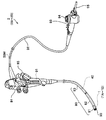
- the endoscope 2 includes an insertion portion 80, an operation portion 84 disposed on the proximal end side of the insertion portion 80, and a universal cord extending from the operation portion 84. 92 and a connector 93 disposed on the base end side of the universal cord 92.
- the insertion portion 80 includes a hard tip portion 81, a bending portion 82 for changing the direction of the tip portion 81, and an elongated flexible soft portion 83 connected in order.
- the distal end portion 81 includes an imaging optical unit 90L, an imaging element 90, and an optical transmission module 1 that is an E / O module that converts an imaging signal (electric signal) from the imaging element 90 into an optical signal.
- the image sensor 90 is a CMOS (Complementary Metal Oxide Semiconductor) image sensor, a CCD (Charge Coupled Device), or the like.
- the operation section 84 is provided with an angle knob 85 for operating the bending section 82 and an O / E module 91 which is an optical transmission module for converting an optical signal into an electric signal.
- the connector 93 has an electrical connector portion 94 that is connected to a processor (not shown), and a light guide connection portion 95 that is connected to a light source.
- the light guide connection portion 95 is connected to an optical fiber bundle that guides illumination light to the hard tip portion 81.
- the electrical connector portion 94 and the light guide connecting portion 95 may be integrated.
- the imaging signal is converted into an optical signal by the optical transmission module 1 or the like that is an E / O module disposed at the distal end portion 81, and is operated via the thin optical fiber 40 that is inserted through the insertion portion 80. Part 84 is transmitted. Then, the optical signal is converted again into an electrical signal by the O / E module 91 provided in the operation unit 84 and transmitted to the electrical connector unit 94 via the metal wiring 50M through which the universal cord 92 is inserted. That is, a signal is transmitted through the optical fiber 40 in the insertion portion 80 having a small diameter, and is inserted through the metal wiring 50M that is thicker than the optical fiber 40 in the universal cord 92 that is not inserted into the body and has a small outer diameter restriction. Signal is transmitted.
- the optical fiber 40 may pass through the universal cord 92 to the vicinity of the electrical connector portion 94.
- the optical fiber 40 may be inserted up to the connector 93.
- the insertion portion 80 is thin and minimally invasive.
- the optical transmission module 1 of the present embodiment includes an optical element 10 that is a light emitting element, a wiring board 20, a holding member (also referred to as a ferrule) 30, and light that is inserted through an insertion portion 80.
- a fiber 40 and an intermediate member 50 made of glass are provided.
- the optical element 10, the wiring board 20, and the holding member 30 are arranged side by side in the thickness direction (Z direction) of the optical element 10.
- the optical element 10 is a surface emitting laser chip formed on a light emitting surface 10SA whose light emitting portion 11 which is an optical element portion that outputs light of an optical signal is a surface.
- the ultra-small optical element 10 having a planar view size of 250 ⁇ m ⁇ 300 ⁇ m includes a light emitting unit 11 having a diameter of 20 ⁇ m and an external electrode 12 that supplies a drive signal to the light emitting unit 11 on the light emitting surface 10SA.
- the optical fiber 40 includes a core part 41 having a diameter of 50 ⁇ m that transmits light and a clad part 42 having a diameter of 125 ⁇ m that covers the outer peripheral surface of the core part 41.
- the core portion 41 is made of glass having a refractive index slightly smaller than that of the cladding portion 42, for example, about 0.2% to 0.3%.
- the substantially rectangular parallelepiped holding member 30 bonded on the optical element 10 has a through hole H30 into which the tip of the optical fiber 40 is inserted. By inserting and fitting the optical fiber 40 into the through hole H30, the light emitting portion 11 of the optical element 10 and the optical fiber 40 are positioned.
- the inner shape of the through-hole H30 may be a prismatic shape such as a quadrangular prism or a hexagonal prism as long as the optical fiber 40 can be held by the wall surface in addition to the cylindrical shape.
- the material of the holding member 30 is a metal member such as ceramic, silicon, glass or SUS.
- the holding member 30 may have a substantially cylindrical shape or a substantially conical shape.
- the holding member 30 is formed with a cylindrical through hole H30 having substantially the same outer diameter R40 and diameter (inner diameter) R30 of the optical fiber 40 to be inserted.
- substantially the same means that the outer diameter of the optical fiber 40 and the wall surface of the through-hole H30 are in contact with each other and are in a fitted state, and the diameters of both are substantially the same.
- the diameter R30 of the through hole H30 is made larger by 1 ⁇ m to 5 ⁇ m than the outer diameter R40 of the optical fiber 40.
- the flat wiring board 20 having the first main surface 20SA and the second main surface 20SB has a hole H20 serving as an optical path.
- the bonding electrode 21 disposed on the first main surface 20SA of the wiring board 20 and the external electrode 12 of the optical element 10 are bonded via bumps 13. That is, the optical element 10 is flip-chip mounted on the wiring board 20 in a state where the light emitting part 11 is disposed at a position facing the hole H20 of the wiring board 20. Therefore, there is a gap corresponding to the height of the bump 13 between the light emitting portion 11 of the optical element 10 and the first main surface 20SA of the wiring board 20.
- the stud gold bump 13 is ultrasonically bonded to the bonding electrode 21 of the wiring board 20.
- the joint between the external electrode 12 of the optical element 10 and the joint electrode 21 of the wiring board 20 is sealed with a sealing resin 60 that is excellent in moisture resistance and insulation, such as an epoxy resin or a silicone resin.
- an FPC board As the base of the wiring board 20, an FPC board, a ceramic board, a glass epoxy board, a glass board, a silicon board, or the like is used.
- solder paste or the like may be printed on the wiring board 20 to form bumps, and the optical element 10 may be disposed at a predetermined position, and then solder may be melted and mounted by reflow or the like.
- the wiring board 20 may include a processing circuit for converting an electrical signal transmitted from the image sensor 90 into a drive signal for the optical element 10.
- the holding member 30 is bonded to the second main surface 20SB of the wiring board 20 with an adhesive layer 31 in a state where the through hole H30 is disposed at a position facing the hole H20.
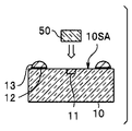
- the intermediate member 50 has an upper surface in contact with the distal end surface of the optical fiber 40 and a lower surface in contact with the light emitting portion 11 of the optical element 10.
- the intermediate member 50 constituting the optical path of the optical signal is made of, for example, glass through which the light of the optical signal is transmitted.
- the intermediate member 50 is bonded to the light emitting portion 11 of the light emitting surface 10SA of the optical element 10 with a transparent adhesive (not shown).
- the lower surface of the intermediate member 50 completely covers the light emitting unit 11 in order to efficiently guide the light generated by the optical element 10 to the optical fiber 40.
- the lower surface of the intermediate member 50 completely covers the light emitting unit 11 in order to efficiently guide the light generated by the optical element 10 to the optical fiber 40.
- it is.
- the intermediate member 50 may be a transparent resin such as a silicone resin, an epoxy resin, or an acrylic resin, as long as it is a material that allows the wavelength of the optical signal to be transmitted satisfactorily. Further, when the wavelength of the optical signal is an infrared wavelength, the intermediate member does not transmit visible light, but may be formed of a material that transmits infrared light, for example, silicon.
- the wiring board 20 and the optical element 10 are joined. That is, the bonding electrode 21 on the first main surface 20SA of the wiring board 20 and the external electrode 12 of the optical element 10 are bonded via the gold bump 13.
- a resin having a light shielding function that does not transmit light of an optical signal may be used as the sealing resin.
- the holding member 30 is bonded to the back surface 20SA of the substrate 20 on which the optical element 10 is mounted. Then, the optical fiber 40 is inserted and fitted into the through hole H30 of the holding member 30 up to a position where the distal end surface comes into contact with the upper surface of the intermediate member 50. The distance between the front end surface of the optical fiber 40 and the light emitting portion 11 of the optical element 10 is accurately positioned by the height of the holding member 30 and fixed by the adhesive 32.
- the optical transmission module 1 has a high coupling efficiency between the optical fiber 40 and the optical element 10 and is easy to manufacture.
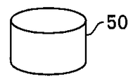
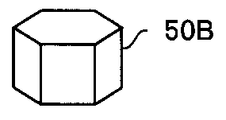
- the shape of the intermediate member is not limited to the cylindrical intermediate member 50 shown in FIG. 5A as long as the lower surface covers the light emitting unit 11.
- the rectangular column intermediate member 50A shown in FIG. 5B or the polygonal column intermediate member 50B shown in FIG. 5C may be used.
- an intermediate member 50C having the same configuration as that of the optical fiber 40 as shown in FIG. 5D It is particularly preferable to use an intermediate member 50C having the same configuration as that of the optical fiber 40 as shown in FIG. 5D. That is, the intermediate member 50C having the clad portion 42 that covers the outer peripheral surface of the core portion 41 in the same manner as the optical fiber 40 has the optical fiber 40 of a predetermined length, that is, the tip surface of the optical fiber 40 and the optical element 10. It can be easily manufactured by cutting it at a distance from the light emitting portion 11. Further, the intermediate member 50C having the same configuration as the optical fiber 40 has high light transmission efficiency.
- the lower surface of the core portion 41 of the intermediate member 50C completely covers the light emitting portion 11 in order to guide the light generated by the optical element 10 to the optical fiber 40 efficiently.
- the intermediate member 50 ⁇ / b> D has a cylindrical shape, that is, a hollow cylindrical shape, and has a through hole H ⁇ b> 50 that is a space serving as an optical path at the center.
- the intermediate member 50D is made of metal, ceramic, resin, or the like.
- the diameter R50 of the through hole H50 of the intermediate member 50D is larger than the outer diameter R11 of the light emitting part 11, and the core part 41 of the optical fiber 40 Is preferably smaller than the outer diameter R41.
- the diameter R50 of the through hole H50 of the intermediate member 50D is conversely smaller than the outer diameter R11 of the light receiving part and the outer diameter R41 of the core part 41 of the optical fiber 40. Is preferably larger.
- the length L50 of the intermediate member 50D is smaller than the distance between the light receiving surface 10SA of the optical element 10 and the lower surface of the holding member 30.
- the optical transmission module 1A can be manufactured at a lower cost than the optical transmission module 1.
- the inside of the through hole H50 may be filled with a transparent resin such as a silicone resin, an epoxy resin, or an acrylic resin.
- a transparent resin such as a silicone resin, an epoxy resin, or an acrylic resin.
- the intermediate member 50D is similar to the intermediate member 50.
- the opening on the upper surface of the through hole H50 has a tapered shape.
- the tip surface of the optical fiber 40 is in contact with the tapered surface.
- the intermediate member 50E can easily arrange the optical fiber 40 perpendicular to the light emitting surface 10SA of the optical element 10.
- the intermediate member 50F shown in FIG. 8B has an outer peripheral surface that is tapered toward the lower surface. Even when the external electrode 12 is disposed near the light emitting portion 11 of the optical element 10, the intermediate member 50 ⁇ / b> F can be easily disposed on the optical element 10.
- optical transmission module 1B according to a third embodiment and an endoscope 2B having the optical transmission module 1B will be described. Since the optical transmission module 1B and the endoscope 2B are similar to the optical transmission module 1 and the endoscope 2 and have the same functions, the same components are denoted by the same reference numerals and description thereof is omitted.
- the intermediate member 50 ⁇ / b> G is long, and the upper part thereof is inserted through the hole H ⁇ b> 20 of the wiring board 20 to the through hole H ⁇ b> 30 of the holding member 30.
- the intermediate member 50G has the same configuration as that of the optical fiber 40, like the holding member 50C (see FIG. 5C). That is, the intermediate member 50G includes a core portion 41 and a cladding portion 42 having an outer diameter R50. However, the intermediate member 50G has a length L50 longer than the holding member 50C.
- the intermediate member 50G is bonded to the light emitting surface 10SA in a state of being aligned with the light emitting unit 11 of the optical element 10.
- the upper part of the intermediate member 50 ⁇ / b> G is inserted into the hole H ⁇ b> 20 of the substrate 20.
- the upper part of the intermediate member 50G is inserted into the through hole H30 of the holding member 30. That is, the outer diameter R50 of the intermediate member 50G is substantially the same size as the diameter of the through hole H30 of the holding member 30 in the same manner as the outer diameter R40 of the optical fiber 40.
- the optical element 10 and the holding member 30 are automatically positioned in the horizontal direction (XY direction). Then, the wiring board 20 and the optical element 10 are joined.
- the optical fiber 40 is automatically inserted into the through-hole H30, and the front end surface comes into contact with the upper surface of the intermediate member 50G, so that the optical fiber 40 is automatically not only in the horizontal direction (XY direction) but also in the vertical direction. Positioning is also performed in the direction (Z direction).
- the light transmission module 1B is easier to manufacture than the light transmission module 1 or the like.
- the same effect as that of the optical transmission module 1B can be obtained by using an intermediate member having the same configuration as the intermediate members 50 to 50D and having a long length instead of the intermediate member 50G. That is, in the optical transmission module in which the upper part of the intermediate member is inserted through the hole of the wiring board and inserted into the through hole of the holding member, the optical fiber is inserted into the through hole, and the tip end surface is in contact with the upper surface of the intermediate member. Thus, positioning is automatically performed not only in the horizontal direction (XY direction) but also in the vertical direction (Z direction) with respect to the light emitting unit.
- the upper part of the intermediate member 50 ⁇ / b> H is tapered at the entire circumference, and the upper part is inserted through the hole H ⁇ b> 20 of the wiring board 20 and the through hole H ⁇ b> 30 of the holding member 30. Is inserted and fitted.
- the optical transmission module 1C is easy to insert the upper part of the intermediate member 50H into the through hole H30 of the holding member 30. For this reason, the optical transmission module 1C is easier to manufacture than the optical transmission module 1B.
- the outer diameter R50 of the intermediate member 50I is smaller than the outer diameter R40 of the optical fiber 40.
- the diameter of the through hole H30 of the holding member 30 is different between the upper part and the lower part. That is, in the through hole H30, the upper diameter R50 is substantially the same as the outer diameter R40 of the optical fiber 40, and the lower diameter R50A is substantially the same as the outer diameter R50 of the intermediate member 50I.
- the light transmission module 1D has the same effect as the light transmission module 1B.
- the cross-sectional shape of the lower part of the through-hole H30 of the holding member 30 is made rectangular or polygonal. The same effect as that of the transmission module 1B can be obtained.
- optical transmission module etc. which comprise the light emitting element as the optical element 10 were demonstrated above as an example.
- the optical element is an O / E optical transmission module of a light receiving element having a light receiving portion such as a photodiode, the same effect can be obtained as long as it has the same configuration.
- the O / E light transmission module disposed at the distal end portion of the endoscope transmits, for example, a clock signal input to the image sensor as an optical signal.
- An endoscope that transmits a clock signal through a thin optical fiber 40 has a thin insertion portion 80 and is minimally invasive.
- an optical fiber that transmits an optical signal, a light receiving unit on which the optical signal is incident, and an external electrode are disposed on the front surface.
- a light receiving element, a holding member having a through hole into which the optical fiber is inserted, and a hole serving as an optical path for the optical signal, and the holding member is bonded to the first main surface.
- an intermediate member having an upper surface in contact with the front end surface of the optical fiber and a lower surface in contact with the light receiving portion of the light receiving element.
Abstract
An optical transmission module 1 is provided with: an optical fiber 40; a light emitting element 10; a holding member 30 having a through hole H30 into which the optical fiber 40 is inserted; a wiring board 20, wherein the holding member 30 is bonded to a first main surface 20SA, and a bonding electrode 21 disposed on a second main surface 20SB, and an external electrode 12 of the light emitting element 10 are bonded to each other; and a sealing resin 60 that seals a bonding section between the external electrode 12 and the bonding electrode 21. The optical transmission module is also provided with an intermediate member 50 having the upper surface thereof in contact with the leading end surface of the optical fiber 40, and the lower surface thereof in contact with a light emitting section 11 of the light emitting element 10.
Description
本発明は、光信号を伝送する光ファイバと、光素子と、前記光ファイバが挿入されている貫通孔のある保持部材と、前記光信号の光路となる孔部があり第1の主面に前記保持部材が接着され、第2の主面に前記光素子が実装されている配線板と、を具備する光伝送モジュール、および前記光伝送モジュールを挿入部の先端部に有する内視鏡に関する。
The present invention has an optical fiber for transmitting an optical signal, an optical element, a holding member having a through hole into which the optical fiber is inserted, and a hole serving as an optical path for the optical signal on the first main surface. The present invention relates to an optical transmission module including a wiring board to which the holding member is bonded and the optical element is mounted on a second main surface, and an endoscope having the optical transmission module at a distal end portion of an insertion portion.
内視鏡は、細長い可撓性の挿入部の先端部にCCD等の撮像素子を有する。近年、高画素数の撮像素子の内視鏡への使用が検討されている。高画素数の撮像素子を使用した場合には、撮像素子から信号処理装置(プロセッサ)へ伝送する信号量が増加するため、電気信号によるメタル配線を介した電気信号伝送に替えて光信号による細い光ファイバを介した光信号伝送が好ましい。光信号伝送には、電気信号を光信号に変換するE/O光伝送モジュール(電気-光変換器)と、光信号を電気信号に変換するO/E光伝送モジュール(光-電気変換器)とが用いられる。
The endoscope has an image sensor such as a CCD at the distal end of an elongated flexible insertion portion. In recent years, use of an imaging device having a high pixel number for an endoscope has been studied. When an image sensor with a large number of pixels is used, the amount of signal transmitted from the image sensor to the signal processing device (processor) increases. Therefore, instead of electric signal transmission through metal wiring by electric signals, thin signals by optical signals are used. Optical signal transmission via an optical fiber is preferred. For optical signal transmission, an E / O optical transmission module (electric-optical converter) that converts electrical signals into optical signals, and an O / E optical transmission module (optical-electrical converter) that converts optical signals into electrical signals And are used.
光伝送モジュールは光素子と光信号を伝送する光ファイバとを効率良く光結合するために正確な位置決めと固定とが重要である。光素子と光ファイバとを、正確に、かつ簡単に位置決めするために、光伝送モジュールには、光素子が実装されている配線板に配設された貫通孔(スルホール)を有する保持部材(フェルール)が用いられる。光ファイバを保持部材の貫通孔に挿入することで、光素子と光ファイバとの水平方向を簡単に位置決めできる。正確に位置決めするために、貫通孔の径は、光ファイバの外径よりも僅かに大きく設定されている。
In an optical transmission module, accurate positioning and fixing are important in order to efficiently optically couple an optical element and an optical fiber that transmits an optical signal. In order to accurately and easily position the optical element and the optical fiber, the optical transmission module has a holding member (ferrule) having a through hole (through hole) disposed in the wiring board on which the optical element is mounted. ) Is used. By inserting the optical fiber into the through hole of the holding member, the horizontal direction between the optical element and the optical fiber can be easily positioned. In order to accurately position, the diameter of the through hole is set slightly larger than the outer diameter of the optical fiber.
日本国特開2014-10329号公報には、光素子と光ファイバ端面との距離、すなわち、垂直方向を正確に、かつ簡単に位置決めするために、光素子が実装された配線板の孔部のテーパー状に形成し、光ファイバの先端面を孔部に当接することが開示されている。
In Japanese Patent Application Laid-Open No. 2014-10329, in order to accurately and easily position the distance between the optical element and the end face of the optical fiber, that is, the vertical direction, the hole of the wiring board on which the optical element is mounted is provided. It is disclosed that the optical fiber is formed in a tapered shape and the tip surface of the optical fiber is brought into contact with the hole.
しかし、配線板に所定のテーパー形状の孔部を形成するには高精度の加工が必要であり、また、設計自由度が低下する。このため、配線板の作製費用等が高くなり、光伝送モジュールのコストが高くなるおそれがあった。
However, in order to form a predetermined tapered hole in the wiring board, high-precision processing is required, and the degree of design freedom is reduced. For this reason, the production cost of a wiring board etc. became high and there existed a possibility that the cost of an optical transmission module might become high.
また、配線板と光素子との接合部を封止樹脂により封止するときに、封止樹脂が光素子の発光部にまで広がってしまい光ファイバに導光される光量が減少し、光ファイバと光素子との結合効率が低下するおそれがあった。
In addition, when the joint between the wiring board and the optical element is sealed with the sealing resin, the sealing resin spreads to the light emitting portion of the optical element, and the amount of light guided to the optical fiber is reduced. The coupling efficiency between the optical element and the optical element may be reduced.
本発明の実施形態は、光ファイバと光素子との結合効率が高い製造が容易な光伝送モジュール、および前記光伝送モジュールを挿入部の先端部に有する内視鏡を提供することを目的とする。
An embodiment of the present invention aims to provide an optical transmission module that has a high coupling efficiency between an optical fiber and an optical element and that can be easily manufactured, and an endoscope that has the optical transmission module at the distal end of an insertion portion. .
実施形態の内視鏡は、撮像素子が配設された先端部に光伝送モジュールを有する挿入部と、前記挿入部の基端部側に延設された操作部と、を具備する内視鏡であって、
前記光伝送モジュールが、光信号を伝送するコア部と、前記コア部の外周面を覆うクラッド部と、を有し、前記挿入部を挿通している光ファイバと、前記光信号を出射または前記光信号が入射する光素子部と外部電極とがおもて面に配設されている光素子と、前記光ファイバが挿入されている貫通孔のある保持部材と、前記光信号の光路となる孔部があり、第1の主面に前記保持部材が接着され第2の主面に配設されている接合電極と前記光素子の前記外部電極とが接合されている配線板と、前記外部電極と前記接合電極との接合部を封止している封止樹脂と、を具備し、
上面が前記光ファイバの先端面と当接し、下面が前記光素子の前記光素子部と当接している、前記光ファイバと同じ構成の、中間部材をさらに具備し、全周が先細りにテーパー加工されている前記中間部材の上部が前記保持部材の前記貫通孔に挿入されている。 An endoscope according to an embodiment includes an insertion portion having a light transmission module at a distal end portion where an imaging element is disposed, and an operation portion extended to a proximal end portion side of the insertion portion. Because
The optical transmission module includes a core part that transmits an optical signal, and a cladding part that covers an outer peripheral surface of the core part, and an optical fiber that passes through the insertion part, and emits the optical signal or An optical element in which an optical element portion on which an optical signal is incident and an external electrode are arranged on the front surface, a holding member having a through hole into which the optical fiber is inserted, and an optical path of the optical signal A wiring board having a hole, the holding member being bonded to the first main surface and the bonding electrode disposed on the second main surface and the external electrode of the optical element being bonded; A sealing resin that seals the joint between the electrode and the joining electrode,
The optical fiber further includes an intermediate member having the same configuration as the optical fiber, wherein the upper surface is in contact with the front end surface of the optical fiber and the lower surface is in contact with the optical element portion of the optical element, and the entire circumference is tapered. An upper portion of the intermediate member is inserted into the through hole of the holding member.
別の実施形態の光伝送モジュールは、光信号を伝送する光ファイバと前記光信号を出射または前記光信号が入射する光素子部と外部電極とがおもて面に配設されている光素子と、前記光ファイバが挿入されている貫通孔のある保持部材と、前記光信号の光路となる孔部があり、第1の主面に前記保持部材が接着され第2の主面に配設されている接合電極と前記光素子の前記外部電極とが接合されている配線板と、前記外部電極と前記接合電極との接合部を封止している封止樹脂と、を具備し、上面が前記光ファイバの先端面と当接し、下面が前記光素子の前記光素子部と当接している、中間部材をさらに具備する。
An optical transmission module according to another embodiment is an optical element in which an optical fiber that transmits an optical signal, an optical element portion that emits the optical signal or that receives the optical signal, and an external electrode are disposed on the front surface. And a holding member having a through hole into which the optical fiber is inserted and a hole serving as an optical path for the optical signal, and the holding member is bonded to the first main surface and disposed on the second main surface. A wiring board in which the bonded electrode and the external electrode of the optical element are bonded; and a sealing resin that seals a bonded portion between the external electrode and the bonded electrode; Further includes an intermediate member in contact with the front end surface of the optical fiber and a lower surface in contact with the optical element portion of the optical element.
本発明の実施形態によれば、光ファイバと光素子との結合効率が高い製造が容易な光伝送モジュール、および前記光伝送モジュールを挿入部の先端部に有する内視鏡を提供できる。
According to the embodiment of the present invention, it is possible to provide an optical transmission module that has a high coupling efficiency between an optical fiber and an optical element and that can be easily manufactured, and an endoscope that has the optical transmission module at the distal end of the insertion portion.
<第1実施形態>
図1に示すように、本実施形態の内視鏡2は、挿入部80と、挿入部80の基端部側に配設された操作部84と、操作部84から延設されたユニバーサルコード92と、ユニバーサルコード92の基端部側に配設されたコネクタ93と、を具備する。 <First Embodiment>
As shown in FIG. 1, theendoscope 2 according to the present embodiment includes an insertion portion 80, an operation portion 84 disposed on the proximal end side of the insertion portion 80, and a universal cord extending from the operation portion 84. 92 and a connector 93 disposed on the base end side of the universal cord 92.
図1に示すように、本実施形態の内視鏡2は、挿入部80と、挿入部80の基端部側に配設された操作部84と、操作部84から延設されたユニバーサルコード92と、ユニバーサルコード92の基端部側に配設されたコネクタ93と、を具備する。 <First Embodiment>
As shown in FIG. 1, the
挿入部80は、硬性の先端部81と、先端部81の方向を変えるための湾曲部82と、細長い可撓性の軟性部83と、が順に連接されている。
The insertion portion 80 includes a hard tip portion 81, a bending portion 82 for changing the direction of the tip portion 81, and an elongated flexible soft portion 83 connected in order.
先端部81には、撮像光学ユニット90Lと、撮像素子90と、撮像素子90からの撮像信号(電気信号)を光信号に変換するE/Oモジュールである光伝送モジュール1が配設されている。撮像素子90は、CMOS(Complementary Metal Oxide Semiconductor)イメージセンサ、または、CCD(Charge Coupled Device)等である。
The distal end portion 81 includes an imaging optical unit 90L, an imaging element 90, and an optical transmission module 1 that is an E / O module that converts an imaging signal (electric signal) from the imaging element 90 into an optical signal. . The image sensor 90 is a CMOS (Complementary Metal Oxide Semiconductor) image sensor, a CCD (Charge Coupled Device), or the like.
操作部84には湾曲部82を操作するアングルノブ85が配設されているとともに、光信号を電気信号に変換する光伝送モジュールであるO/Eモジュール91が配設されている。コネクタ93は、プロセッサ(不図示)と接続される電気コネクタ部94と、光源と接続されるライトガイド接続部95と、を有する。ライトガイド接続部95は硬性先端部81まで照明光を導光する光ファイババンドルと接続されている。なおコネクタ93は、電気コネクタ部94とライトガイド接続部95とが一体となっていても良い。
The operation section 84 is provided with an angle knob 85 for operating the bending section 82 and an O / E module 91 which is an optical transmission module for converting an optical signal into an electric signal. The connector 93 has an electrical connector portion 94 that is connected to a processor (not shown), and a light guide connection portion 95 that is connected to a light source. The light guide connection portion 95 is connected to an optical fiber bundle that guides illumination light to the hard tip portion 81. In the connector 93, the electrical connector portion 94 and the light guide connecting portion 95 may be integrated.
内視鏡2では、撮像信号は先端部81に配設されたE/Oモジュールである光伝送モジュール1等で光信号に変換されて、挿入部80を挿通する細い光ファイバ40を介して操作部84まで伝送される。そして、操作部84に配設されているO/Eモジュール91により光信号は再び電気信号に変換され、ユニバーサルコード92を挿通するメタル配線50Mを介して電気コネクタ部94に伝送される。すなわち、細径の挿入部80内においては光ファイバ40を介して信号が伝送され、体内に挿入されず外径の制限の小さいユニバーサルコード92内においては光ファイバ40よりも太いメタル配線50Mを介して信号が伝送される。
In the endoscope 2, the imaging signal is converted into an optical signal by the optical transmission module 1 or the like that is an E / O module disposed at the distal end portion 81, and is operated via the thin optical fiber 40 that is inserted through the insertion portion 80. Part 84 is transmitted. Then, the optical signal is converted again into an electrical signal by the O / E module 91 provided in the operation unit 84 and transmitted to the electrical connector unit 94 via the metal wiring 50M through which the universal cord 92 is inserted. That is, a signal is transmitted through the optical fiber 40 in the insertion portion 80 having a small diameter, and is inserted through the metal wiring 50M that is thicker than the optical fiber 40 in the universal cord 92 that is not inserted into the body and has a small outer diameter restriction. Signal is transmitted.
なお、O/Eモジュール91が電気コネクタ部94の近傍に配置されている場合には、光ファイバ40は電気コネクタ部94の近傍までユニバーサルコード92を挿通していてもよい。また、O/Eモジュール91がプロセッサに配設されている場合には、光ファイバ40はコネクタ93まで挿通していてもよい。
When the O / E module 91 is disposed in the vicinity of the electrical connector portion 94, the optical fiber 40 may pass through the universal cord 92 to the vicinity of the electrical connector portion 94. When the O / E module 91 is disposed in the processor, the optical fiber 40 may be inserted up to the connector 93.
内視鏡2は、電気信号伝送に替えて光信号による細い光ファイバ40を介した光信号伝送を行うため、挿入部80が細く低侵襲である。
Since the endoscope 2 performs optical signal transmission through the thin optical fiber 40 using an optical signal instead of electrical signal transmission, the insertion portion 80 is thin and minimally invasive.
図2に示すように、本実施形態の光伝送モジュール1は、発光素子である光素子10と、配線板20と、保持部材(フェルールともいう)30と、挿入部80を挿通している光ファイバ40と、ガラスからなる中間(intermediate)部材50と、を具備する。光伝送モジュール1では、光素子10と配線板20と保持部材30とが、光素子10の厚さ方向(Z方向)に並べて配置されている。
As shown in FIG. 2, the optical transmission module 1 of the present embodiment includes an optical element 10 that is a light emitting element, a wiring board 20, a holding member (also referred to as a ferrule) 30, and light that is inserted through an insertion portion 80. A fiber 40 and an intermediate member 50 made of glass are provided. In the optical transmission module 1, the optical element 10, the wiring board 20, and the holding member 30 are arranged side by side in the thickness direction (Z direction) of the optical element 10.
なお、以下の説明において、各実施の形態に基づく図面は、模式的なものであり、各部分の厚みと幅との関係、夫々の部分の厚みの比率および相対角度などは現実のものとは異なることに留意すべきであり、図面の相互間においても互いの寸法の関係や比率が異なる部分が含まれている場合がある。また、Z軸の値が増加する方向を「上」という。
In the following description, the drawings based on each embodiment are schematic, and the relationship between the thickness and width of each part, the ratio of the thickness of each part, the relative angle, and the like are actual. It should be noted that there is a case where portions having different dimensional relationships and ratios are included in the drawings. The direction in which the Z-axis value increases is referred to as “up”.
光素子10は、光信号の光を出力する光素子部である発光部11が表面(おもてめん)である発光面10SAに形成された面発光レーザーチップである。例えば、平面視寸法が250μm×300μmと超小型の光素子10は、直径が20μmの発光部11と、発光部11に駆動信号を供給する外部電極12と、を発光面10SAに有する。
The optical element 10 is a surface emitting laser chip formed on a light emitting surface 10SA whose light emitting portion 11 which is an optical element portion that outputs light of an optical signal is a surface. For example, the ultra-small optical element 10 having a planar view size of 250 μm × 300 μm includes a light emitting unit 11 having a diameter of 20 μm and an external electrode 12 that supplies a drive signal to the light emitting unit 11 on the light emitting surface 10SA.
一方、例えば、光ファイバ40は、光を伝送する50μm径のコア部41と、コア部41の外周面を覆う125μm径のクラッド部42とを有する。コア部41はクラッド部42よりも屈折率が僅かに、例えば、0.2%~0.3%程度、小さいガラスからなる。
On the other hand, for example, the optical fiber 40 includes a core part 41 having a diameter of 50 μm that transmits light and a clad part 42 having a diameter of 125 μm that covers the outer peripheral surface of the core part 41. The core portion 41 is made of glass having a refractive index slightly smaller than that of the cladding portion 42, for example, about 0.2% to 0.3%.
光素子10の上に接着されている略直方体の保持部材30には光ファイバ40の先端部が挿入されている貫通孔(Through hole)H30がある。光ファイバ40を貫通孔H30に挿入し嵌合することで、光素子10の発光部11と光ファイバ40との位置決めが行われる。貫通孔H30の内形は、円柱状のほか、その壁面で光ファイバ40を保持できれば、四角柱または六角柱等の角柱状であってもよい。保持部材30の材質はセラミック、シリコン、ガラスまたはSUS等の金属部材等である。なお、保持部材30は、略円柱状または略円錐状等であってもよい。
The substantially rectangular parallelepiped holding member 30 bonded on the optical element 10 has a through hole H30 into which the tip of the optical fiber 40 is inserted. By inserting and fitting the optical fiber 40 into the through hole H30, the light emitting portion 11 of the optical element 10 and the optical fiber 40 are positioned. The inner shape of the through-hole H30 may be a prismatic shape such as a quadrangular prism or a hexagonal prism as long as the optical fiber 40 can be held by the wall surface in addition to the cylindrical shape. The material of the holding member 30 is a metal member such as ceramic, silicon, glass or SUS. The holding member 30 may have a substantially cylindrical shape or a substantially conical shape.
すでに説明したように、保持部材30には、挿入される光ファイバ40の外径R40と、径(内径)R30が略同じ円柱状の貫通孔H30が形成されている。ここで「略同じ」とは、光ファイバ40の外周面と貫通孔H30の壁面とが当接し嵌合状態となるような、双方の径が実質的に「同じ」サイズであることを意味する。例えば、光ファイバ40の外径R40に対して、貫通孔H30の径R30は1μm~5μmだけ大きく作製される。
As already described, the holding member 30 is formed with a cylindrical through hole H30 having substantially the same outer diameter R40 and diameter (inner diameter) R30 of the optical fiber 40 to be inserted. Here, “substantially the same” means that the outer diameter of the optical fiber 40 and the wall surface of the through-hole H30 are in contact with each other and are in a fitted state, and the diameters of both are substantially the same. . For example, the diameter R30 of the through hole H30 is made larger by 1 μm to 5 μm than the outer diameter R40 of the optical fiber 40.
第1の主面20SAと第2の主面20SBとを有する平板状の配線板20には、光路となる孔部H20がある。配線板20の第1の主面20SAに配設されている接合電極21と光素子10の外部電極12とが、バンプ13を介して接合されている。すなわち、光素子10は、発光部11が配線板20の孔部H20と対向する位置に配置された状態で配線板20にフリップチップ実装されている。このため、光素子10の発光部11と配線板20の第1の主面20SAとの間には、バンプ13の高さに相当する隙間がある。例えば、スタッド金バンプ13が、配線板20の接合電極21と超音波接合されている。
The flat wiring board 20 having the first main surface 20SA and the second main surface 20SB has a hole H20 serving as an optical path. The bonding electrode 21 disposed on the first main surface 20SA of the wiring board 20 and the external electrode 12 of the optical element 10 are bonded via bumps 13. That is, the optical element 10 is flip-chip mounted on the wiring board 20 in a state where the light emitting part 11 is disposed at a position facing the hole H20 of the wiring board 20. Therefore, there is a gap corresponding to the height of the bump 13 between the light emitting portion 11 of the optical element 10 and the first main surface 20SA of the wiring board 20. For example, the stud gold bump 13 is ultrasonically bonded to the bonding electrode 21 of the wiring board 20.
光素子10の外部電極12と配線板20の接合電極21との接合部は、エポキシ樹脂、またはシリコーン樹脂等の耐湿性および絶縁性に優れた封止樹脂60により封止されている。
The joint between the external electrode 12 of the optical element 10 and the joint electrode 21 of the wiring board 20 is sealed with a sealing resin 60 that is excellent in moisture resistance and insulation, such as an epoxy resin or a silicone resin.
配線板20の基体には、FPC基板、セラミック基板、ガラスエポキシ基板、ガラス基板、またはシリコン基板等が使用される。
As the base of the wiring board 20, an FPC board, a ceramic board, a glass epoxy board, a glass board, a silicon board, or the like is used.
なお配線板20に、半田ペースト等を印刷してバンプとし、光素子10を所定位置に配置した後、リフロー等で半田を溶融して実装してもよい。なお、配線板20は、撮像素子90から伝送されてくる電気信号を光素子10の駆動信号に変換するための処理回路等が含まれていてもよい。
Note that solder paste or the like may be printed on the wiring board 20 to form bumps, and the optical element 10 may be disposed at a predetermined position, and then solder may be melted and mounted by reflow or the like. The wiring board 20 may include a processing circuit for converting an electrical signal transmitted from the image sensor 90 into a drive signal for the optical element 10.
配線板20の第2の主面20SBには保持部材30が、貫通孔H30が孔部H20と対向する位置に配置された状態で接着層31により接着されている。
The holding member 30 is bonded to the second main surface 20SB of the wiring board 20 with an adhesive layer 31 in a state where the through hole H30 is disposed at a position facing the hole H20.
中間部材50は、上面が光ファイバ40の先端面と当接し、下面が光素子10の発光部11と当接している。光信号の光路を構成している中間部材50は、光信号の光が透過する、例えばガラスからなる。
The intermediate member 50 has an upper surface in contact with the distal end surface of the optical fiber 40 and a lower surface in contact with the light emitting portion 11 of the optical element 10. The intermediate member 50 constituting the optical path of the optical signal is made of, for example, glass through which the light of the optical signal is transmitted.
図3に示すように、光伝送モジュール1の製造方法では、最初に光素子10の発光面10SAの発光部11に中間部材50が透明接着剤(不図示)により接着される。
As shown in FIG. 3, in the method for manufacturing the optical transmission module 1, first, the intermediate member 50 is bonded to the light emitting portion 11 of the light emitting surface 10SA of the optical element 10 with a transparent adhesive (not shown).
なお、光素子10として発光素子を有する光伝送モジュール1では、光素子10が発生した光を効率良く光ファイバ40に導光するために、中間部材50の下面が発光部11を完全に覆っていることが好ましい。
In the optical transmission module 1 having a light emitting element as the optical element 10, the lower surface of the intermediate member 50 completely covers the light emitting unit 11 in order to efficiently guide the light generated by the optical element 10 to the optical fiber 40. Preferably it is.
また、中間部材50は光信号の波長が良好に透過する材料であれば、シリコーン系樹脂、エポキシ系樹脂、またはアクリル系樹脂などの透明樹脂でもよい。また、光信号の波長が赤外波長の場合は、中間部材は可視光は透化しないが、赤外光は透過する材料、例えば、シリコンから構成されていてもよい。
Further, the intermediate member 50 may be a transparent resin such as a silicone resin, an epoxy resin, or an acrylic resin, as long as it is a material that allows the wavelength of the optical signal to be transmitted satisfactorily. Further, when the wavelength of the optical signal is an infrared wavelength, the intermediate member does not transmit visible light, but may be formed of a material that transmits infrared light, for example, silicon.
次に図4に示すように、まず、配線板20と光素子10とが接合される。すなわち、配線板20の第1の主面20SAの接合電極21と光素子10の外部電極12とが、金バンプ13を介して接合される。
Next, as shown in FIG. 4, first, the wiring board 20 and the optical element 10 are joined. That is, the bonding electrode 21 on the first main surface 20SA of the wiring board 20 and the external electrode 12 of the optical element 10 are bonded via the gold bump 13.
その後、接合電極21と外部電極12との接合部に液体状の封止樹脂が注入され硬化処理される。光伝送モジュール1では発光部11は、中間部材50で覆われているため、未硬化の封止樹脂が発光部11にまで広がってしまうおそれがない。
Thereafter, a liquid sealing resin is injected into the joint portion between the joining electrode 21 and the external electrode 12 and cured. In the light transmission module 1, since the light emitting unit 11 is covered with the intermediate member 50, there is no possibility that uncured sealing resin spreads to the light emitting unit 11.
封止樹脂として光信号の光を透過しない遮光機能を有する樹脂を用いてもよい。
A resin having a light shielding function that does not transmit light of an optical signal may be used as the sealing resin.
その後、光素子10を実装した基板20の裏面20SAに保持部材30が接着される。そして、光ファイバ40が、先端面が中間部材50の上面と当接する位置まで保持部材30の貫通孔H30に挿入され嵌合する。光ファイバ40の先端面と光素子10の発光部11との距離は、保持部材30の高さにより正確に位置決めされ、接着剤32で固定される。
Thereafter, the holding member 30 is bonded to the back surface 20SA of the substrate 20 on which the optical element 10 is mounted. Then, the optical fiber 40 is inserted and fitted into the through hole H30 of the holding member 30 up to a position where the distal end surface comes into contact with the upper surface of the intermediate member 50. The distance between the front end surface of the optical fiber 40 and the light emitting portion 11 of the optical element 10 is accurately positioned by the height of the holding member 30 and fixed by the adhesive 32.
このため、光伝送モジュール1は、光ファイバ40と光素子10との結合効率が高く、かつ、製造が容易である。
For this reason, the optical transmission module 1 has a high coupling efficiency between the optical fiber 40 and the optical element 10 and is easy to manufacture.
<第1実施形態の変形例>
なお、中間部材の形状は、下面が発光部11を覆っていれば、図5Aに示す円柱の中間部材50に限られない。例えば、図5Bに示す四角柱の中間部材50A、または図5Cに示す多角柱の中間部材50Bでもよい。 <Modification of First Embodiment>
The shape of the intermediate member is not limited to the cylindricalintermediate member 50 shown in FIG. 5A as long as the lower surface covers the light emitting unit 11. For example, the rectangular column intermediate member 50A shown in FIG. 5B or the polygonal column intermediate member 50B shown in FIG. 5C may be used.
なお、中間部材の形状は、下面が発光部11を覆っていれば、図5Aに示す円柱の中間部材50に限られない。例えば、図5Bに示す四角柱の中間部材50A、または図5Cに示す多角柱の中間部材50Bでもよい。 <Modification of First Embodiment>
The shape of the intermediate member is not limited to the cylindrical
そして、図5Dに示すような、光ファイバ40と同じ構成の中間部材50Cを用いることが特に好ましい。すなわち、光ファイバ40と同じようにコア部41の外周面を覆うクラッド部42とを有する中間部材50Cは、光ファイバ40を所定の長さ、すなわち、光ファイバ40の先端面と光素子10の発光部11との距離、に切断することで容易に作製できる。また、光ファイバ40と同じ構成の中間部材50Cは、光の伝送効率が高い。
It is particularly preferable to use an intermediate member 50C having the same configuration as that of the optical fiber 40 as shown in FIG. 5D. That is, the intermediate member 50C having the clad portion 42 that covers the outer peripheral surface of the core portion 41 in the same manner as the optical fiber 40 has the optical fiber 40 of a predetermined length, that is, the tip surface of the optical fiber 40 and the optical element 10. It can be easily manufactured by cutting it at a distance from the light emitting portion 11. Further, the intermediate member 50C having the same configuration as the optical fiber 40 has high light transmission efficiency.
なお、光素子10が発生した光を効率良く光ファイバ40に導光するために、中間部材50Cのコア部41の下面が発光部11を完全に覆っていることが好ましい。
In addition, it is preferable that the lower surface of the core portion 41 of the intermediate member 50C completely covers the light emitting portion 11 in order to guide the light generated by the optical element 10 to the optical fiber 40 efficiently.
<第2実施形態>
第2実施形態の光伝送モジュール1Aおよび光伝送モジュール1Aを有する内視鏡2Aについて説明する。光伝送モジュール1Aおよび内視鏡2Aは、光伝送モジュール1および内視鏡2と類似し、同じ機能を有するため、同じ構成要素には同じ符号を付し説明は省略する。 Second Embodiment
Anendoscope 2A having the light transmission module 1A and the light transmission module 1A of the second embodiment will be described. Since the light transmission module 1A and the endoscope 2A are similar to the light transmission module 1 and the endoscope 2 and have the same functions, the same components are denoted by the same reference numerals and description thereof is omitted.
第2実施形態の光伝送モジュール1Aおよび光伝送モジュール1Aを有する内視鏡2Aについて説明する。光伝送モジュール1Aおよび内視鏡2Aは、光伝送モジュール1および内視鏡2と類似し、同じ機能を有するため、同じ構成要素には同じ符号を付し説明は省略する。 Second Embodiment
An
図6に示すように、光伝送モジュール1Aでは中間部材50Dは、筒状、すなわち中空円筒状で、中央に光路となる空間である貫通孔H50がある。中間部材50Dは、金属、セラミック、または樹脂等からなる。
As shown in FIG. 6, in the optical transmission module 1 </ b> A, the intermediate member 50 </ b> D has a cylindrical shape, that is, a hollow cylindrical shape, and has a through hole H <b> 50 that is a space serving as an optical path at the center. The intermediate member 50D is made of metal, ceramic, resin, or the like.
図7に示すように、光素子10として発光素子を有する光伝送モジュール1Aでは、中間部材50Dの貫通孔H50の径R50は、発光部11の外径R11より大きく、光ファイバ40のコア部41の外径R41よりも小さいことが好ましい。なお、光素子10として受光素子を有する光伝送モジュールでは、中間部材50Dの貫通孔H50の径R50は、逆に、受光部の外径R11より小さく、光ファイバ40のコア部41の外径R41よりも大きいことが好ましい。なお、中間部材50Dの長さL50は、光素子10の受光面10SAと保持部材30の下面との距離より小さい。
As shown in FIG. 7, in the optical transmission module 1A having a light emitting element as the optical element 10, the diameter R50 of the through hole H50 of the intermediate member 50D is larger than the outer diameter R11 of the light emitting part 11, and the core part 41 of the optical fiber 40 Is preferably smaller than the outer diameter R41. In the optical transmission module having the light receiving element as the optical element 10, the diameter R50 of the through hole H50 of the intermediate member 50D is conversely smaller than the outer diameter R11 of the light receiving part and the outer diameter R41 of the core part 41 of the optical fiber 40. Is preferably larger. The length L50 of the intermediate member 50D is smaller than the distance between the light receiving surface 10SA of the optical element 10 and the lower surface of the holding member 30.
光伝送モジュール1Aは、光伝送モジュール1よりも安価に製造できる。
The optical transmission module 1A can be manufactured at a lower cost than the optical transmission module 1.
なお、貫通孔H50の内部が、シリコーン系樹脂、エポキシ系樹脂、またはアクリル系樹脂などの透明樹脂で充填されていてもよい。この場合には、中間部材50Dは中間部材50と類似している。
Note that the inside of the through hole H50 may be filled with a transparent resin such as a silicone resin, an epoxy resin, or an acrylic resin. In this case, the intermediate member 50D is similar to the intermediate member 50.
<第2実施形態の変形例>
図8Aに示す中間部材50Eは、貫通孔H50の上面の開口がテーパー形状となっている。そして、光ファイバ40の先端面が、テーパー面と当接している。中間部材50Eは、光ファイバ40を光素子10の発光面10SAに対して垂直に配置することが容易である。 <Modification of Second Embodiment>
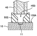
In theintermediate member 50E shown in FIG. 8A, the opening on the upper surface of the through hole H50 has a tapered shape. The tip surface of the optical fiber 40 is in contact with the tapered surface. The intermediate member 50E can easily arrange the optical fiber 40 perpendicular to the light emitting surface 10SA of the optical element 10.
図8Aに示す中間部材50Eは、貫通孔H50の上面の開口がテーパー形状となっている。そして、光ファイバ40の先端面が、テーパー面と当接している。中間部材50Eは、光ファイバ40を光素子10の発光面10SAに対して垂直に配置することが容易である。 <Modification of Second Embodiment>
In the
図8Bに示す中間部材50Fは、外周面が下面に向けてテーパー形状となっている。光素子10の発光部11の近くに外部電極12が配設されている場合であっても、中間部材50Fは光素子10に配設することが容易である。
The intermediate member 50F shown in FIG. 8B has an outer peripheral surface that is tapered toward the lower surface. Even when the external electrode 12 is disposed near the light emitting portion 11 of the optical element 10, the intermediate member 50 </ b> F can be easily disposed on the optical element 10.
<第3実施形態>
第3実施形態の光伝送モジュール1Bおよび光伝送モジュール1Bを有する内視鏡2Bについて説明する。光伝送モジュール1Bおよび内視鏡2Bは、光伝送モジュール1および内視鏡2と類似し、同じ機能を有するため、同じ構成要素には同じ符号を付し説明は省略する。 <Third Embodiment>
Anoptical transmission module 1B according to a third embodiment and an endoscope 2B having the optical transmission module 1B will be described. Since the optical transmission module 1B and the endoscope 2B are similar to the optical transmission module 1 and the endoscope 2 and have the same functions, the same components are denoted by the same reference numerals and description thereof is omitted.
第3実施形態の光伝送モジュール1Bおよび光伝送モジュール1Bを有する内視鏡2Bについて説明する。光伝送モジュール1Bおよび内視鏡2Bは、光伝送モジュール1および内視鏡2と類似し、同じ機能を有するため、同じ構成要素には同じ符号を付し説明は省略する。 <Third Embodiment>
An
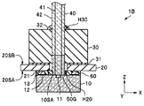
図9に示すように、光伝送モジュール1Bでは、中間部材50Gの長さが長くその上部が、配線板20の孔部H20を挿通し、保持部材30の貫通孔H30にまで挿入されている。
As shown in FIG. 9, in the optical transmission module 1 </ b> B, the intermediate member 50 </ b> G is long, and the upper part thereof is inserted through the hole H <b> 20 of the wiring board 20 to the through hole H <b> 30 of the holding member 30.
図10に示すように、中間部材50Gは、保持部材50C(図5C参照)と同じように、光ファイバ40と同じ構成である。すなわち、中間部材50Gは、コア部41と外径がR50のクラッド部42とからなる。ただし、中間部材50Gは保持部材50Cよりも長さL50が長い。
As shown in FIG. 10, the intermediate member 50G has the same configuration as that of the optical fiber 40, like the holding member 50C (see FIG. 5C). That is, the intermediate member 50G includes a core portion 41 and a cladding portion 42 having an outer diameter R50. However, the intermediate member 50G has a length L50 longer than the holding member 50C.
光伝送モジュール1Bの製造方法では、図10に示すように、まず、中間部材50Gが光素子10の発光部11に位置合わせした状態で、発光面10SAに接着される。次に、図11に示すように、中間部材50Gの上部が基板20の孔部H20に挿入される。その後、保持部材30の貫通孔H30に中間部材50Gの上部が挿入される。すなわち、中間部材50Gの外径R50は、光ファイバ40の外径R40と同じように、保持部材30の貫通孔H30の径と実質的に「同じ」サイズである
中間部材50Gが貫通孔H30に挿入されと嵌合することで、光素子10と保持部材30の水平方向(XY方向)の位置決めが自動的に行われる。そして配線板20と光素子10とが接合される。 In the method for manufacturing theoptical transmission module 1B, as shown in FIG. 10, first, the intermediate member 50G is bonded to the light emitting surface 10SA in a state of being aligned with the light emitting unit 11 of the optical element 10. Next, as shown in FIG. 11, the upper part of the intermediate member 50 </ b> G is inserted into the hole H <b> 20 of the substrate 20. Thereafter, the upper part of the intermediate member 50G is inserted into the through hole H30 of the holding member 30. That is, the outer diameter R50 of the intermediate member 50G is substantially the same size as the diameter of the through hole H30 of the holding member 30 in the same manner as the outer diameter R40 of the optical fiber 40. By inserting and fitting, the optical element 10 and the holding member 30 are automatically positioned in the horizontal direction (XY direction). Then, the wiring board 20 and the optical element 10 are joined.
中間部材50Gが貫通孔H30に挿入されと嵌合することで、光素子10と保持部材30の水平方向(XY方向)の位置決めが自動的に行われる。そして配線板20と光素子10とが接合される。 In the method for manufacturing the
光ファイバ40が貫通孔H30に挿入され、先端面が中間部材50Gの上面と当接することで、光ファイバ40は、自動的に、発光部11に対して水平方向(XY方向)だけでなく垂直方向(Z方向)も位置決めが行われる。
The optical fiber 40 is automatically inserted into the through-hole H30, and the front end surface comes into contact with the upper surface of the intermediate member 50G, so that the optical fiber 40 is automatically not only in the horizontal direction (XY direction) but also in the vertical direction. Positioning is also performed in the direction (Z direction).
光伝送モジュール1Bは、光伝送モジュール1等よりも、製造が容易である。
The light transmission module 1B is easier to manufacture than the light transmission module 1 or the like.
なお、中間部材50Gに替えて、中間部材50~50Dと同じ構成で長さの長い中間部材を用いても、光伝送モジュール1Bと同じ効果が得られる。すなわち、中間部材の上部が配線板の孔部を挿通し保持部材の貫通孔に挿入されている光伝送モジュールは、光ファイバが貫通孔に挿入され、先端面が中間部材の上面と当接することで、自動的に、発光部に対して水平方向(XY方向)だけでなく垂直方向(Z方向)も位置決めが行われる。
Note that the same effect as that of the optical transmission module 1B can be obtained by using an intermediate member having the same configuration as the intermediate members 50 to 50D and having a long length instead of the intermediate member 50G. That is, in the optical transmission module in which the upper part of the intermediate member is inserted through the hole of the wiring board and inserted into the through hole of the holding member, the optical fiber is inserted into the through hole, and the tip end surface is in contact with the upper surface of the intermediate member. Thus, positioning is automatically performed not only in the horizontal direction (XY direction) but also in the vertical direction (Z direction) with respect to the light emitting unit.
<第4実施形態>
第4実施形態の光伝送モジュール1Cおよび光伝送モジュール1Cを有する内視鏡2Cについて説明する。光伝送モジュール1Cおよび内視鏡2Cは、光伝送モジュール1Bおよび内視鏡2Bと類似し、同じ機能を有するため、同じ構成要素には同じ符号を付し説明は省略する。 <Fourth embodiment>
Anoptical transmission module 1C according to a fourth embodiment and an endoscope 2C having the optical transmission module 1C will be described. Since the light transmission module 1C and the endoscope 2C are similar to the light transmission module 1B and the endoscope 2B and have the same functions, the same components are denoted by the same reference numerals and description thereof is omitted.
第4実施形態の光伝送モジュール1Cおよび光伝送モジュール1Cを有する内視鏡2Cについて説明する。光伝送モジュール1Cおよび内視鏡2Cは、光伝送モジュール1Bおよび内視鏡2Bと類似し、同じ機能を有するため、同じ構成要素には同じ符号を付し説明は省略する。 <Fourth embodiment>
An
図12に示すように、光伝送モジュール1Cでは、中間部材50Hの上部が、全周が先細りにテーパー加工されており、上部が配線板20の孔部H20を挿通し保持部材30の貫通孔H30に挿入され嵌合している。
As shown in FIG. 12, in the optical transmission module 1 </ b> C, the upper part of the intermediate member 50 </ b> H is tapered at the entire circumference, and the upper part is inserted through the hole H <b> 20 of the wiring board 20 and the through hole H <b> 30 of the holding member 30. Is inserted and fitted.
光伝送モジュール1Cは、中間部材50Hの上部を保持部材30の貫通孔H30に挿入するのが容易である。このため、光伝送モジュール1Cは、光伝送モジュール1Bよりも、製造が容易である。
The optical transmission module 1C is easy to insert the upper part of the intermediate member 50H into the through hole H30 of the holding member 30. For this reason, the optical transmission module 1C is easier to manufacture than the optical transmission module 1B.
<第5実施形態>
第5実施形態の光伝送モジュール1Dおよび光伝送モジュール1Dを有する内視鏡2Dについて説明する。光伝送モジュール1Dおよび内視鏡2Dは、光伝送モジュール1Bおよび内視鏡2Bと類似し、同じ機能を有するため、同じ構成要素には同じ符号を付し説明は省略する。 <Fifth Embodiment>
Anoptical transmission module 1D according to a fifth embodiment and an endoscope 2D having the optical transmission module 1D will be described. Since the light transmission module 1D and the endoscope 2D are similar to the light transmission module 1B and the endoscope 2B and have the same functions, the same components are denoted by the same reference numerals and description thereof is omitted.
第5実施形態の光伝送モジュール1Dおよび光伝送モジュール1Dを有する内視鏡2Dについて説明する。光伝送モジュール1Dおよび内視鏡2Dは、光伝送モジュール1Bおよび内視鏡2Bと類似し、同じ機能を有するため、同じ構成要素には同じ符号を付し説明は省略する。 <Fifth Embodiment>
An
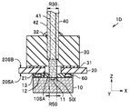
図13に示すように、光伝送モジュール1Dでは、中間部材50Iの外径R50が光ファイバ40の外径R40よりも小さい。そして、保持部材30の貫通孔H30の径が上部と下部とで異なる。すなわち、貫通孔H30は、上部の径R50は、光ファイバ40の外径R40と略同じであり、下部の径R50Aは、中間部材50Iの外径R50と略同じである。
As shown in FIG. 13, in the optical transmission module 1D, the outer diameter R50 of the intermediate member 50I is smaller than the outer diameter R40 of the optical fiber 40. The diameter of the through hole H30 of the holding member 30 is different between the upper part and the lower part. That is, in the through hole H30, the upper diameter R50 is substantially the same as the outer diameter R40 of the optical fiber 40, and the lower diameter R50A is substantially the same as the outer diameter R50 of the intermediate member 50I.
光伝送モジュール1Dは、光伝送モジュール1Bと同じ効果を有する。
The light transmission module 1D has the same effect as the light transmission module 1B.
なお、直方体の中間部材50A(図5B)、多角柱の中間部材50B(図5C)の場合には、保持部材30の貫通孔H30の下部の断面形状を矩形または多角形とすることで、光伝送モジュール1Bと同じ効果を得ることができる。
In the case of the rectangular parallelepiped intermediate member 50A (FIG. 5B) and the polygonal intermediate member 50B (FIG. 5C), the cross-sectional shape of the lower part of the through-hole H30 of the holding member 30 is made rectangular or polygonal. The same effect as that of the transmission module 1B can be obtained.
なお、以上では、光素子10として発光素子を具備する光伝送モジュール等を例に説明した。しかし、光素子がフォトダイオード等の受光部を有する受光素子のO/E光伝送モジュールであっても同様の構成を有していれば同様の効果を有することは言うまでも無い。
In addition, the optical transmission module etc. which comprise the light emitting element as the optical element 10 were demonstrated above as an example. However, it goes without saying that even if the optical element is an O / E optical transmission module of a light receiving element having a light receiving portion such as a photodiode, the same effect can be obtained as long as it has the same configuration.
内視鏡の先端部に配設されたO/E光伝送モジュールは、例えば、撮像素子に入力されるクロック信号を光信号として伝送する。細い光ファイバ40を介してクロック信号を伝送する内視鏡は挿入部80が細く低侵襲である。
The O / E light transmission module disposed at the distal end portion of the endoscope transmits, for example, a clock signal input to the image sensor as an optical signal. An endoscope that transmits a clock signal through a thin optical fiber 40 has a thin insertion portion 80 and is minimally invasive.
以上の説明のように、本発明の別の実施形態の光伝送モジュールは、光信号を伝送する光ファイバと前記光信号が入射する受光部と外部電極とがおもて面に配設されている受光素子と、前記光ファイバが挿入されている貫通孔のある保持部材と、前記光信号の光路となる孔部があり、第1の主面に前記保持部材が接着され第2の主面に配設されている接合電極と前記光素子の前記外部電極とが接合されている配線板と、前記外部電極と前記接合電極との接合部を封止している封止樹脂と、を具備し、上面が前記光ファイバの先端面と当接し、下面が前記受光素子の前記受光部と当接している、中間部材をさらに具備する。
As described above, in the optical transmission module according to another embodiment of the present invention, an optical fiber that transmits an optical signal, a light receiving unit on which the optical signal is incident, and an external electrode are disposed on the front surface. A light receiving element, a holding member having a through hole into which the optical fiber is inserted, and a hole serving as an optical path for the optical signal, and the holding member is bonded to the first main surface. A wiring board on which the bonding electrode disposed on the optical element and the external electrode of the optical element are bonded; and a sealing resin that seals a bonding portion between the external electrode and the bonding electrode. And an intermediate member having an upper surface in contact with the front end surface of the optical fiber and a lower surface in contact with the light receiving portion of the light receiving element.
本発明は、上述した実施形態および変形例等に限定されるものではなく、発明の趣旨を逸脱しない範囲内において種々の変更、組み合わせおよび応用が可能である。
The present invention is not limited to the above-described embodiments and modifications, and various modifications, combinations, and applications are possible without departing from the spirit of the invention.
1、1A~1D・・・光伝送モジュール
2、2A~2D・・・内視鏡
10・・・光素子
11・・・発光部
12・・・外部電極
13・・・バンプ
20・・・配線板
H20・・・孔部
21・・・接合電極
30・・・保持部材
H30・・・貫通孔
40・・・光ファイバ
50・・・中間部材
60・・・封止樹脂
80・・・挿入部
81・・・先端部
90・・・撮像素子 DESCRIPTION OF SYMBOLS 1, 1A-1D ... Optical transmission module 2, 2A-2D ... Endoscope 10 ... Optical element 11 ... Light emission part 12 ... External electrode 13 ... Bump 20 ... Wiring Plate H20 ... Hole 21 ... Bonding electrode 30 ... Holding member H30 ... Through hole 40 ... Optical fiber 50 ... Intermediate member 60 ... Sealing resin 80 ... Insertion part 81 ... tip 90 ... image sensor
2、2A~2D・・・内視鏡
10・・・光素子
11・・・発光部
12・・・外部電極
13・・・バンプ
20・・・配線板
H20・・・孔部
21・・・接合電極
30・・・保持部材
H30・・・貫通孔
40・・・光ファイバ
50・・・中間部材
60・・・封止樹脂
80・・・挿入部
81・・・先端部
90・・・撮像素子 DESCRIPTION OF
Claims (7)
- 撮像素子が配設された先端部に光伝送モジュールを有する挿入部と、
前記挿入部の基端部側に延設された操作部と、を具備する内視鏡であって、
前記光伝送モジュールが、
光信号を伝送するコア部と、前記コア部の外周面を覆うクラッド部と、を有し、前記挿入部を挿通している光ファイバと
前記光信号を出射または前記光信号が入射する光素子部と外部電極とがおもて面に配設されている光素子と、
前記光ファイバが挿入されている貫通孔のある保持部材と、
前記光信号の光路となる孔部があり、第1の主面に前記保持部材が接着され第2の主面に配設されている接合電極と前記光素子の前記外部電極とが接合されている配線板と、
前記外部電極と前記接合電極との接合部を封止している封止樹脂と、を具備し、
上面が前記光ファイバの先端面と当接し、下面が前記光素子の前記光素子部と当接している、前記光ファイバと同じ構成の、中間部材をさらに具備し、全周が先細りにテーパー加工されている前記中間部材の上部が前記保持部材の前記貫通孔に挿入されていることを特徴とする内視鏡。 An insertion part having an optical transmission module at the tip part where the image sensor is disposed;
An endoscope including an operation unit extending on a proximal end side of the insertion unit,
The optical transmission module is
An optical element having a core part for transmitting an optical signal, and a clad part covering the outer peripheral surface of the core part, and an optical fiber through which the insertion part is inserted, and an optical element that emits the optical signal or receives the optical signal An optical element in which a portion and an external electrode are disposed on the front surface;
A holding member having a through hole into which the optical fiber is inserted;
There is a hole serving as an optical path for the optical signal, the holding member is bonded to the first main surface, and the bonding electrode disposed on the second main surface is bonded to the external electrode of the optical element. A wiring board,
A sealing resin that seals a joint between the external electrode and the joint electrode;
The optical fiber further includes an intermediate member having the same configuration as the optical fiber, wherein the upper surface is in contact with the front end surface of the optical fiber and the lower surface is in contact with the optical element portion of the optical element, and the entire circumference is tapered. An endoscope, wherein an upper portion of the intermediate member is inserted into the through hole of the holding member. - 光信号を伝送する光ファイバと
前記光信号を出射または前記光信号が入射する光素子部と外部電極とがおもて面に配設されている光素子と、
前記光ファイバが挿入されている貫通孔のある保持部材と、
前記光信号の光路となる孔部があり、第1の主面に前記保持部材が接着され第2の主面に配設されている接合電極と前記光素子の前記外部電極とが接合されている配線板と、
前記外部電極と前記接合電極との接合部を封止している封止樹脂と、を具備する光伝送モジュールであって、
上面が前記光ファイバの先端面と当接し、下面が前記光素子の前記光素子部と当接している、中間部材をさらに具備することを特徴とする光伝送モジュール。 An optical fiber that transmits an optical signal, an optical element that emits the optical signal or that receives the optical signal, and an external electrode disposed on the front surface; and
A holding member having a through hole into which the optical fiber is inserted;
There is a hole serving as an optical path for the optical signal, the holding member is bonded to the first main surface, and the bonding electrode disposed on the second main surface is bonded to the external electrode of the optical element. A wiring board,
An optical transmission module comprising: a sealing resin that seals a joint between the external electrode and the joint electrode;
An optical transmission module, further comprising an intermediate member, wherein an upper surface is in contact with a front end surface of the optical fiber, and a lower surface is in contact with the optical element portion of the optical element. - 前記中間部材が透明材料からなることを特徴とする請求項2に記載の光伝送モジュール。 The optical transmission module according to claim 2, wherein the intermediate member is made of a transparent material.
- 前記中間部材が前記光ファイバと同じ構成の透明材料からなることを特徴とする請求項2に記載の光伝送モジュール。 3. The optical transmission module according to claim 2, wherein the intermediate member is made of a transparent material having the same configuration as the optical fiber.
- 前記中間部材に前記光路となる空間があることを特徴とする請求項2に記載の光伝送モジュール。 The optical transmission module according to claim 2, wherein the intermediate member has a space serving as the optical path.
- 前記中間部材の上部が、前記保持部材の前記貫通孔と嵌合していることを特徴とする請求項2から請求項5のいずれか1項に記載の光伝送モジュール。 The optical transmission module according to any one of claims 2 to 5, wherein an upper portion of the intermediate member is fitted into the through hole of the holding member.
- 前記中間部材が、前記光ファイバと同じ構成を有し、
前記中間部材の上部が、全周が先細りにテーパー加工されており、
前記中間部材の上部の一部が、前記保持部材の前記貫通孔と嵌合していることを特徴とする請求項2に記載の光伝送モジュール。 The intermediate member has the same configuration as the optical fiber,
The upper part of the intermediate member is tapered on the entire circumference, and
The optical transmission module according to claim 2, wherein a part of an upper portion of the intermediate member is fitted into the through hole of the holding member.
Priority Applications (3)
| Application Number | Priority Date | Filing Date | Title |
|---|---|---|---|
| PCT/JP2015/065232 WO2016189691A1 (en) | 2015-05-27 | 2015-05-27 | Endoscope and optical transmission module |
| JP2017520155A JPWO2016189691A1 (en) | 2015-05-27 | 2015-05-27 | Endoscope and light transmission module |
| US15/811,952 US20180078114A1 (en) | 2015-05-27 | 2017-11-14 | Endoscope and optical transmission module |
Applications Claiming Priority (1)
| Application Number | Priority Date | Filing Date | Title |
|---|---|---|---|
| PCT/JP2015/065232 WO2016189691A1 (en) | 2015-05-27 | 2015-05-27 | Endoscope and optical transmission module |
Related Child Applications (1)
| Application Number | Title | Priority Date | Filing Date |
|---|---|---|---|
| US15/811,952 Continuation US20180078114A1 (en) | 2015-05-27 | 2017-11-14 | Endoscope and optical transmission module |
Publications (1)
| Publication Number | Publication Date |
|---|---|
| WO2016189691A1 true WO2016189691A1 (en) | 2016-12-01 |
Family
ID=57392977
Family Applications (1)
| Application Number | Title | Priority Date | Filing Date |
|---|---|---|---|
| PCT/JP2015/065232 WO2016189691A1 (en) | 2015-05-27 | 2015-05-27 | Endoscope and optical transmission module |
Country Status (3)
| Country | Link |
|---|---|
| US (1) | US20180078114A1 (en) |
| JP (1) | JPWO2016189691A1 (en) |
| WO (1) | WO2016189691A1 (en) |
Cited By (7)
| Publication number | Priority date | Publication date | Assignee | Title |
|---|---|---|---|---|
| WO2018139406A1 (en) * | 2017-01-24 | 2018-08-02 | オリンパス株式会社 | Endoscope and endoscope manufacturing method |
| WO2018138962A1 (en) * | 2017-01-24 | 2018-08-02 | オリンパス株式会社 | Endoscope |
| US20180289263A1 (en) * | 2017-03-30 | 2018-10-11 | Nan M. Jokerst | Devices and methods for endoscopic optical assessment of tissue histology |
| WO2020065757A1 (en) * | 2018-09-26 | 2020-04-02 | オリンパス株式会社 | Endoscopic imaging device, endoscope, and endoscopic imaging device production method |
| WO2020079754A1 (en) * | 2018-10-16 | 2020-04-23 | オリンパス株式会社 | Endoscope optical transducer, endoscope, and method for manufacturing endoscope optical transducer |
| WO2020178972A1 (en) * | 2019-03-05 | 2020-09-10 | オリンパス株式会社 | Endoscope optical transducer, endoscope, and method for manufacturing endoscope optical transducer |
| US11971534B2 (en) | 2021-08-06 | 2024-04-30 | Olympus Corporation | Optical transducer for endoscope, endoscope, and manufacturing method of optical transducer for endoscope |
Citations (5)
| Publication number | Priority date | Publication date | Assignee | Title |
|---|---|---|---|---|
| JP2007271674A (en) * | 2006-03-30 | 2007-10-18 | Kyocera Corp | Optical device |
| JP2009251224A (en) * | 2008-04-04 | 2009-10-29 | Sumitomo Electric Ind Ltd | Optical module and method for assembling the same |
| JP2013025092A (en) * | 2011-07-21 | 2013-02-04 | Olympus Corp | Optical element module, optical transmission module, and method of manufacturing optical transmission module |
| JP2015087744A (en) * | 2013-09-26 | 2015-05-07 | オリンパス株式会社 | Optical transmission module, and endoscope |
| WO2015072225A1 (en) * | 2013-11-18 | 2015-05-21 | オリンパス株式会社 | Endoscope |
Family Cites Families (8)
| Publication number | Priority date | Publication date | Assignee | Title |
|---|---|---|---|---|
| DE3382085D1 (en) * | 1982-07-31 | 1991-02-07 | Sumitomo Electric Industries | LIGHT GUIDE. |
| JP2003110802A (en) * | 2001-09-27 | 2003-04-11 | Fuji Photo Film Co Ltd | Imaging apparatus |
| US20030071318A1 (en) * | 2001-10-11 | 2003-04-17 | Szu-Chun Wang | Optical sub-assembly housing structure for an optical transceiver module |
| US20040252951A1 (en) * | 2003-05-12 | 2004-12-16 | Seiko Epson Corporation | Optical module and manufacturing method of the same |
| EP1741136A2 (en) * | 2004-04-13 | 2007-01-10 | SA Intexys | Method for production of electronic and optoelectronic circuits |
| KR101190334B1 (en) * | 2008-10-20 | 2012-10-11 | 오므론 가부시키가이샤 | Light projecting device and sensor |
| DE102010028167A1 (en) * | 2010-04-23 | 2011-10-27 | W.O.M. World Of Medicine Ag | Invasive instrument for processing vessels and a procedure |
| JP5704878B2 (en) * | 2010-09-30 | 2015-04-22 | オリンパス株式会社 | Photoelectric conversion connector, optical transmission module, imaging device, and endoscope |
-
2015
- 2015-05-27 WO PCT/JP2015/065232 patent/WO2016189691A1/en active Application Filing
- 2015-05-27 JP JP2017520155A patent/JPWO2016189691A1/en active Pending
-
2017
- 2017-11-14 US US15/811,952 patent/US20180078114A1/en not_active Abandoned
Patent Citations (5)
| Publication number | Priority date | Publication date | Assignee | Title |
|---|---|---|---|---|
| JP2007271674A (en) * | 2006-03-30 | 2007-10-18 | Kyocera Corp | Optical device |
| JP2009251224A (en) * | 2008-04-04 | 2009-10-29 | Sumitomo Electric Ind Ltd | Optical module and method for assembling the same |
| JP2013025092A (en) * | 2011-07-21 | 2013-02-04 | Olympus Corp | Optical element module, optical transmission module, and method of manufacturing optical transmission module |
| JP2015087744A (en) * | 2013-09-26 | 2015-05-07 | オリンパス株式会社 | Optical transmission module, and endoscope |
| WO2015072225A1 (en) * | 2013-11-18 | 2015-05-21 | オリンパス株式会社 | Endoscope |
Cited By (10)
| Publication number | Priority date | Publication date | Assignee | Title |
|---|---|---|---|---|
| WO2018139406A1 (en) * | 2017-01-24 | 2018-08-02 | オリンパス株式会社 | Endoscope and endoscope manufacturing method |
| WO2018138962A1 (en) * | 2017-01-24 | 2018-08-02 | オリンパス株式会社 | Endoscope |
| WO2018138778A1 (en) * | 2017-01-24 | 2018-08-02 | オリンパス株式会社 | Endoscope |
| US10819960B2 (en) | 2017-01-24 | 2020-10-27 | Olympus Corporation | Endoscope |
| US10972707B2 (en) | 2017-01-24 | 2021-04-06 | Olympus Corporation | Endoscope and method of manufacturing endoscope |
| US20180289263A1 (en) * | 2017-03-30 | 2018-10-11 | Nan M. Jokerst | Devices and methods for endoscopic optical assessment of tissue histology |
| WO2020065757A1 (en) * | 2018-09-26 | 2020-04-02 | オリンパス株式会社 | Endoscopic imaging device, endoscope, and endoscopic imaging device production method |
| WO2020079754A1 (en) * | 2018-10-16 | 2020-04-23 | オリンパス株式会社 | Endoscope optical transducer, endoscope, and method for manufacturing endoscope optical transducer |
| WO2020178972A1 (en) * | 2019-03-05 | 2020-09-10 | オリンパス株式会社 | Endoscope optical transducer, endoscope, and method for manufacturing endoscope optical transducer |
| US11971534B2 (en) | 2021-08-06 | 2024-04-30 | Olympus Corporation | Optical transducer for endoscope, endoscope, and manufacturing method of optical transducer for endoscope |
Also Published As
| Publication number | Publication date |
|---|---|
| US20180078114A1 (en) | 2018-03-22 |
| JPWO2016189691A1 (en) | 2018-03-15 |
Similar Documents
| Publication | Publication Date | Title |
|---|---|---|
| JP6411088B2 (en) | Optical transmission module and endoscope | |
| WO2016189691A1 (en) | Endoscope and optical transmission module | |
| US9385249B2 (en) | Optical element module, optical transmission module, and method of manufacturing optical transmission module | |
| WO2018150512A1 (en) | Optical module, endoscope, and method for manufacturing optical module | |
| JP6321933B2 (en) | Optical transmission module and endoscope | |
| US10088669B2 (en) | Endoscope | |
| WO2016185537A1 (en) | Endoscope and light transmitting module | |
| JP6485840B2 (en) | Optical transmission module and endoscope | |
| US10568491B2 (en) | Endoscope | |
| WO2018198188A1 (en) | Endoscope and imaging module | |
| WO2018134933A1 (en) | Optical module and endoscope | |
| WO2018092233A1 (en) | Optical module, image pickup module, and endoscope | |
| WO2018138962A1 (en) | Endoscope | |
| US10470642B2 (en) | Optical transmitter and endoscope | |
| WO2018092234A1 (en) | Optical module, image pickup module, and endoscope | |
| JP2015097588A (en) | Optical transmission module and endoscope | |
| JP6081160B2 (en) | Optical element module, optical transmission module, and optical transmission module manufacturing method | |
| WO2020217277A1 (en) | Manufacturing method for imaging device for endoscope, imaging device for endoscope, and endoscope | |
| JP2018105907A (en) | Optical module and endoscope | |
| WO2020075253A1 (en) | Endoscopic imaging device, endoscope, and production method for endoscopic imaging device | |
| WO2017115413A1 (en) | Optical transmission module and endoscope |
Legal Events
| Date | Code | Title | Description |
|---|---|---|---|
| 121 | Ep: the epo has been informed by wipo that ep was designated in this application |
Ref document number: 15893325 Country of ref document: EP Kind code of ref document: A1 |
|
| ENP | Entry into the national phase |
Ref document number: 2017520155 Country of ref document: JP Kind code of ref document: A |
|
| NENP | Non-entry into the national phase |
Ref country code: DE |
|
| 122 | Ep: pct application non-entry in european phase |
Ref document number: 15893325 Country of ref document: EP Kind code of ref document: A1 |