US10960768B2 - Vehicle power supply system - Google Patents
Vehicle power supply system Download PDFInfo
- Publication number
- US10960768B2 US10960768B2 US16/368,883 US201916368883A US10960768B2 US 10960768 B2 US10960768 B2 US 10960768B2 US 201916368883 A US201916368883 A US 201916368883A US 10960768 B2 US10960768 B2 US 10960768B2
- Authority
- US
- United States
- Prior art keywords
- power
- power storage
- battery
- upper limit
- value
- Prior art date
- Legal status (The legal status is an assumption and is not a legal conclusion. Google has not performed a legal analysis and makes no representation as to the accuracy of the status listed.)
- Active, expires
Links
Images


Classifications
-
- H—ELECTRICITY
- H02—GENERATION; CONVERSION OR DISTRIBUTION OF ELECTRIC POWER
- H02P—CONTROL OR REGULATION OF ELECTRIC MOTORS, ELECTRIC GENERATORS OR DYNAMO-ELECTRIC CONVERTERS; CONTROLLING TRANSFORMERS, REACTORS OR CHOKE COILS
- H02P3/00—Arrangements for stopping or slowing electric motors, generators, or dynamo-electric converters
- H02P3/06—Arrangements for stopping or slowing electric motors, generators, or dynamo-electric converters for stopping or slowing an individual dynamo-electric motor or dynamo-electric converter
- H02P3/18—Arrangements for stopping or slowing electric motors, generators, or dynamo-electric converters for stopping or slowing an individual dynamo-electric motor or dynamo-electric converter for stopping or slowing an ac motor
-
- B—PERFORMING OPERATIONS; TRANSPORTING
- B60—VEHICLES IN GENERAL
- B60L—PROPULSION OF ELECTRICALLY-PROPELLED VEHICLES; SUPPLYING ELECTRIC POWER FOR AUXILIARY EQUIPMENT OF ELECTRICALLY-PROPELLED VEHICLES; ELECTRODYNAMIC BRAKE SYSTEMS FOR VEHICLES IN GENERAL; MAGNETIC SUSPENSION OR LEVITATION FOR VEHICLES; MONITORING OPERATING VARIABLES OF ELECTRICALLY-PROPELLED VEHICLES; ELECTRIC SAFETY DEVICES FOR ELECTRICALLY-PROPELLED VEHICLES
- B60L53/00—Methods of charging batteries, specially adapted for electric vehicles; Charging stations or on-board charging equipment therefor; Exchange of energy storage elements in electric vehicles
- B60L53/20—Methods of charging batteries, specially adapted for electric vehicles; Charging stations or on-board charging equipment therefor; Exchange of energy storage elements in electric vehicles characterised by converters located in the vehicle
-
- B—PERFORMING OPERATIONS; TRANSPORTING
- B60—VEHICLES IN GENERAL
- B60L—PROPULSION OF ELECTRICALLY-PROPELLED VEHICLES; SUPPLYING ELECTRIC POWER FOR AUXILIARY EQUIPMENT OF ELECTRICALLY-PROPELLED VEHICLES; ELECTRODYNAMIC BRAKE SYSTEMS FOR VEHICLES IN GENERAL; MAGNETIC SUSPENSION OR LEVITATION FOR VEHICLES; MONITORING OPERATING VARIABLES OF ELECTRICALLY-PROPELLED VEHICLES; ELECTRIC SAFETY DEVICES FOR ELECTRICALLY-PROPELLED VEHICLES
- B60L58/00—Methods or circuit arrangements for monitoring or controlling batteries or fuel cells, specially adapted for electric vehicles
- B60L58/10—Methods or circuit arrangements for monitoring or controlling batteries or fuel cells, specially adapted for electric vehicles for monitoring or controlling batteries
- B60L58/12—Methods or circuit arrangements for monitoring or controlling batteries or fuel cells, specially adapted for electric vehicles for monitoring or controlling batteries responding to state of charge [SoC]
-
- B—PERFORMING OPERATIONS; TRANSPORTING
- B60—VEHICLES IN GENERAL
- B60L—PROPULSION OF ELECTRICALLY-PROPELLED VEHICLES; SUPPLYING ELECTRIC POWER FOR AUXILIARY EQUIPMENT OF ELECTRICALLY-PROPELLED VEHICLES; ELECTRODYNAMIC BRAKE SYSTEMS FOR VEHICLES IN GENERAL; MAGNETIC SUSPENSION OR LEVITATION FOR VEHICLES; MONITORING OPERATING VARIABLES OF ELECTRICALLY-PROPELLED VEHICLES; ELECTRIC SAFETY DEVICES FOR ELECTRICALLY-PROPELLED VEHICLES
- B60L7/00—Electrodynamic brake systems for vehicles in general
- B60L7/10—Dynamic electric regenerative braking
- B60L7/14—Dynamic electric regenerative braking for vehicles propelled by ac motors
-
- B—PERFORMING OPERATIONS; TRANSPORTING
- B60—VEHICLES IN GENERAL
- B60L—PROPULSION OF ELECTRICALLY-PROPELLED VEHICLES; SUPPLYING ELECTRIC POWER FOR AUXILIARY EQUIPMENT OF ELECTRICALLY-PROPELLED VEHICLES; ELECTRODYNAMIC BRAKE SYSTEMS FOR VEHICLES IN GENERAL; MAGNETIC SUSPENSION OR LEVITATION FOR VEHICLES; MONITORING OPERATING VARIABLES OF ELECTRICALLY-PROPELLED VEHICLES; ELECTRIC SAFETY DEVICES FOR ELECTRICALLY-PROPELLED VEHICLES
- B60L7/00—Electrodynamic brake systems for vehicles in general
- B60L7/10—Dynamic electric regenerative braking
- B60L7/16—Dynamic electric regenerative braking for vehicles comprising converters between the power source and the motor
-
- H—ELECTRICITY
- H02—GENERATION; CONVERSION OR DISTRIBUTION OF ELECTRIC POWER
- H02P—CONTROL OR REGULATION OF ELECTRIC MOTORS, ELECTRIC GENERATORS OR DYNAMO-ELECTRIC CONVERTERS; CONTROLLING TRANSFORMERS, REACTORS OR CHOKE COILS
- H02P27/00—Arrangements or methods for the control of AC motors characterised by the kind of supply voltage
- H02P27/04—Arrangements or methods for the control of AC motors characterised by the kind of supply voltage using variable-frequency supply voltage, e.g. inverter or converter supply voltage
- H02P27/06—Arrangements or methods for the control of AC motors characterised by the kind of supply voltage using variable-frequency supply voltage, e.g. inverter or converter supply voltage using dc to ac converters or inverters
- H02P27/08—Arrangements or methods for the control of AC motors characterised by the kind of supply voltage using variable-frequency supply voltage, e.g. inverter or converter supply voltage using dc to ac converters or inverters with pulse width modulation
- H02P27/14—Arrangements or methods for the control of AC motors characterised by the kind of supply voltage using variable-frequency supply voltage, e.g. inverter or converter supply voltage using dc to ac converters or inverters with pulse width modulation with three or more levels of voltage
-
- H—ELECTRICITY
- H02—GENERATION; CONVERSION OR DISTRIBUTION OF ELECTRIC POWER
- H02P—CONTROL OR REGULATION OF ELECTRIC MOTORS, ELECTRIC GENERATORS OR DYNAMO-ELECTRIC CONVERTERS; CONTROLLING TRANSFORMERS, REACTORS OR CHOKE COILS
- H02P4/00—Arrangements specially adapted for regulating or controlling the speed or torque of electric motors that can be connected to two or more different electric power supplies
-
- H—ELECTRICITY
- H02—GENERATION; CONVERSION OR DISTRIBUTION OF ELECTRIC POWER
- H02P—CONTROL OR REGULATION OF ELECTRIC MOTORS, ELECTRIC GENERATORS OR DYNAMO-ELECTRIC CONVERTERS; CONTROLLING TRANSFORMERS, REACTORS OR CHOKE COILS
- H02P5/00—Arrangements specially adapted for regulating or controlling the speed or torque of two or more electric motors
- H02P5/74—Arrangements specially adapted for regulating or controlling the speed or torque of two or more electric motors controlling two or more ac dynamo-electric motors
-
- B—PERFORMING OPERATIONS; TRANSPORTING
- B60—VEHICLES IN GENERAL
- B60L—PROPULSION OF ELECTRICALLY-PROPELLED VEHICLES; SUPPLYING ELECTRIC POWER FOR AUXILIARY EQUIPMENT OF ELECTRICALLY-PROPELLED VEHICLES; ELECTRODYNAMIC BRAKE SYSTEMS FOR VEHICLES IN GENERAL; MAGNETIC SUSPENSION OR LEVITATION FOR VEHICLES; MONITORING OPERATING VARIABLES OF ELECTRICALLY-PROPELLED VEHICLES; ELECTRIC SAFETY DEVICES FOR ELECTRICALLY-PROPELLED VEHICLES
- B60L2210/00—Converter types
- B60L2210/40—DC to AC converters
-
- B—PERFORMING OPERATIONS; TRANSPORTING
- B60—VEHICLES IN GENERAL
- B60L—PROPULSION OF ELECTRICALLY-PROPELLED VEHICLES; SUPPLYING ELECTRIC POWER FOR AUXILIARY EQUIPMENT OF ELECTRICALLY-PROPELLED VEHICLES; ELECTRODYNAMIC BRAKE SYSTEMS FOR VEHICLES IN GENERAL; MAGNETIC SUSPENSION OR LEVITATION FOR VEHICLES; MONITORING OPERATING VARIABLES OF ELECTRICALLY-PROPELLED VEHICLES; ELECTRIC SAFETY DEVICES FOR ELECTRICALLY-PROPELLED VEHICLES
- B60L50/00—Electric propulsion with power supplied within the vehicle
- B60L50/50—Electric propulsion with power supplied within the vehicle using propulsion power supplied by batteries or fuel cells
- B60L50/51—Electric propulsion with power supplied within the vehicle using propulsion power supplied by batteries or fuel cells characterised by AC-motors
-
- H—ELECTRICITY
- H02—GENERATION; CONVERSION OR DISTRIBUTION OF ELECTRIC POWER
- H02P—CONTROL OR REGULATION OF ELECTRIC MOTORS, ELECTRIC GENERATORS OR DYNAMO-ELECTRIC CONVERTERS; CONTROLLING TRANSFORMERS, REACTORS OR CHOKE COILS
- H02P2101/00—Special adaptation of control arrangements for generators
- H02P2101/45—Special adaptation of control arrangements for generators for motor vehicles, e.g. car alternators
-
- H—ELECTRICITY
- H02—GENERATION; CONVERSION OR DISTRIBUTION OF ELECTRIC POWER
- H02P—CONTROL OR REGULATION OF ELECTRIC MOTORS, ELECTRIC GENERATORS OR DYNAMO-ELECTRIC CONVERTERS; CONTROLLING TRANSFORMERS, REACTORS OR CHOKE COILS
- H02P2201/00—Indexing scheme relating to controlling arrangements characterised by the converter used
- H02P2201/07—DC-DC step-up or step-down converter inserted between the power supply and the inverter supplying the motor, e.g. to control voltage source fluctuations, to vary the motor speed
-
- Y—GENERAL TAGGING OF NEW TECHNOLOGICAL DEVELOPMENTS; GENERAL TAGGING OF CROSS-SECTIONAL TECHNOLOGIES SPANNING OVER SEVERAL SECTIONS OF THE IPC; TECHNICAL SUBJECTS COVERED BY FORMER USPC CROSS-REFERENCE ART COLLECTIONS [XRACs] AND DIGESTS
- Y02—TECHNOLOGIES OR APPLICATIONS FOR MITIGATION OR ADAPTATION AGAINST CLIMATE CHANGE
- Y02T—CLIMATE CHANGE MITIGATION TECHNOLOGIES RELATED TO TRANSPORTATION
- Y02T10/00—Road transport of goods or passengers
- Y02T10/60—Other road transportation technologies with climate change mitigation effect
- Y02T10/64—Electric machine technologies in electromobility
-
- Y—GENERAL TAGGING OF NEW TECHNOLOGICAL DEVELOPMENTS; GENERAL TAGGING OF CROSS-SECTIONAL TECHNOLOGIES SPANNING OVER SEVERAL SECTIONS OF THE IPC; TECHNICAL SUBJECTS COVERED BY FORMER USPC CROSS-REFERENCE ART COLLECTIONS [XRACs] AND DIGESTS
- Y02—TECHNOLOGIES OR APPLICATIONS FOR MITIGATION OR ADAPTATION AGAINST CLIMATE CHANGE
- Y02T—CLIMATE CHANGE MITIGATION TECHNOLOGIES RELATED TO TRANSPORTATION
- Y02T10/00—Road transport of goods or passengers
- Y02T10/60—Other road transportation technologies with climate change mitigation effect
- Y02T10/70—Energy storage systems for electromobility, e.g. batteries
-
- Y—GENERAL TAGGING OF NEW TECHNOLOGICAL DEVELOPMENTS; GENERAL TAGGING OF CROSS-SECTIONAL TECHNOLOGIES SPANNING OVER SEVERAL SECTIONS OF THE IPC; TECHNICAL SUBJECTS COVERED BY FORMER USPC CROSS-REFERENCE ART COLLECTIONS [XRACs] AND DIGESTS
- Y02—TECHNOLOGIES OR APPLICATIONS FOR MITIGATION OR ADAPTATION AGAINST CLIMATE CHANGE
- Y02T—CLIMATE CHANGE MITIGATION TECHNOLOGIES RELATED TO TRANSPORTATION
- Y02T10/00—Road transport of goods or passengers
- Y02T10/60—Other road transportation technologies with climate change mitigation effect
- Y02T10/7072—Electromobility specific charging systems or methods for batteries, ultracapacitors, supercapacitors or double-layer capacitors
-
- Y—GENERAL TAGGING OF NEW TECHNOLOGICAL DEVELOPMENTS; GENERAL TAGGING OF CROSS-SECTIONAL TECHNOLOGIES SPANNING OVER SEVERAL SECTIONS OF THE IPC; TECHNICAL SUBJECTS COVERED BY FORMER USPC CROSS-REFERENCE ART COLLECTIONS [XRACs] AND DIGESTS
- Y02—TECHNOLOGIES OR APPLICATIONS FOR MITIGATION OR ADAPTATION AGAINST CLIMATE CHANGE
- Y02T—CLIMATE CHANGE MITIGATION TECHNOLOGIES RELATED TO TRANSPORTATION
- Y02T10/00—Road transport of goods or passengers
- Y02T10/60—Other road transportation technologies with climate change mitigation effect
- Y02T10/72—Electric energy management in electromobility
-
- Y—GENERAL TAGGING OF NEW TECHNOLOGICAL DEVELOPMENTS; GENERAL TAGGING OF CROSS-SECTIONAL TECHNOLOGIES SPANNING OVER SEVERAL SECTIONS OF THE IPC; TECHNICAL SUBJECTS COVERED BY FORMER USPC CROSS-REFERENCE ART COLLECTIONS [XRACs] AND DIGESTS
- Y02—TECHNOLOGIES OR APPLICATIONS FOR MITIGATION OR ADAPTATION AGAINST CLIMATE CHANGE
- Y02T—CLIMATE CHANGE MITIGATION TECHNOLOGIES RELATED TO TRANSPORTATION
- Y02T10/00—Road transport of goods or passengers
- Y02T10/80—Technologies aiming to reduce greenhouse gasses emissions common to all road transportation technologies
- Y02T10/92—Energy efficient charging or discharging systems for batteries, ultracapacitors, supercapacitors or double-layer capacitors specially adapted for vehicles
-
- Y—GENERAL TAGGING OF NEW TECHNOLOGICAL DEVELOPMENTS; GENERAL TAGGING OF CROSS-SECTIONAL TECHNOLOGIES SPANNING OVER SEVERAL SECTIONS OF THE IPC; TECHNICAL SUBJECTS COVERED BY FORMER USPC CROSS-REFERENCE ART COLLECTIONS [XRACs] AND DIGESTS
- Y02—TECHNOLOGIES OR APPLICATIONS FOR MITIGATION OR ADAPTATION AGAINST CLIMATE CHANGE
- Y02T—CLIMATE CHANGE MITIGATION TECHNOLOGIES RELATED TO TRANSPORTATION
- Y02T90/00—Enabling technologies or technologies with a potential or indirect contribution to GHG emissions mitigation
- Y02T90/10—Technologies relating to charging of electric vehicles
- Y02T90/14—Plug-in electric vehicles
Definitions
- the disclosure relates to a vehicle power supply system. More specifically, the disclosure relates to a vehicle power supply system including at least two power storage devices and a motor generator.
- electromotive transport instruments including an electric motor as a motive power generation source or electromotive vehicles such as a hybrid vehicle including an electric motor and an internal-combustion engine as a motive power generation source has been actively performed.
- an electric condenser such as a battery or a capacitor is also mounted in order to supply electrical energy to an electric motor.
- a plurality of electric condensers having different characteristics which are mounted in an electromotive vehicle have also been developed.
- Patent Document 1 Japanese Patent Laid-Open No. 2014-143842 discloses a vehicle power supply system including a low-voltage battery, a high-voltage battery, and a converter that converts a voltage.
- the low-voltage battery is connected to a drive motor through the converter
- the high-voltage battery is connected to the drive motor so as to be in parallel with the converter.
- each battery can be charged with regenerative electric power supplied from each drive motor.
- specific ways to supply the regenerative electric power generated in these two drive motors to the two kinds of batteries so that power efficiency in the entire vehicle can be improved have not been examined sufficiently.
- a vehicle power supply system including: a first motor generator connected to a first wheel of a vehicle; a second motor generator connected to a second wheel; a first circuit to which a first power converter that transfers power to and from the first motor generator and a first power storage device are connected; a second circuit to which a second power converter that transfers power to and from the second motor generator and a second power storage device are connected; a voltage converter that converts a voltage between the first circuit and the second circuit; a charging and discharging control device that controls charging and discharging of the first and second power storage devices by operating the first and second power converters and the voltage converter; and a second regenerable electric power acquisition unit that acquires second regenerable electric power that is an upper limit for regenerative electric power supplied to the second power storage device during regenerative deceleration in which regenerative electric power is generated by the first and second motor generators, wherein the charging and discharging control device charges the second power storage device with second regenerative electric power that is power supplied
- FIG. 1 is a diagram illustrating a configuration of an electromotive vehicle in which a power supply system according to an embodiment of the disclosure is mounted.
- FIG. 2 is a diagram illustrating ranges of use of a first battery and a second battery.
- FIG. 3 is a diagram illustrating portions relating to the execution of energy management control among a plurality of control modules configured in an ECU.
- FIG. 4A is a diagram schematically illustrating a flow of power realized in the power supply system when a driving state is a normal traveling state.
- FIG. 4B is a diagram schematically illustrating a flow of power realized in the power supply system when the driving state is a normal traveling state.
- FIG. 4C is a diagram schematically illustrating a flow of power realized in the power supply system when the driving state is a normal traveling state.
- FIG. 5 is a diagram schematically illustrating a flow of power realized in the power supply system when the driving state is a high-output traveling state.
- FIG. 6A is a diagram schematically illustrating a flow of power realized in the power supply system when the driving state is a low-output traveling state.
- FIG. 6B is a diagram schematically illustrating a flow of power realized in the power supply system when the driving state is a low-output traveling state.
- FIG. 7A is a diagram schematically illustrating a flow of power realized in the power supply system when the driving state is a regenerative traveling state.
- FIG. 7B is a diagram schematically illustrating a flow of power realized in the power supply system when the driving state is a regenerative traveling state.
- FIG. 7C is a diagram schematically illustrating a flow of power realized in the power supply system when the driving state is a regenerative traveling state.
- FIG. 7D is a diagram schematically illustrating a flow of power realized in the power supply system when the driving state is a regenerative traveling state.
- FIG. 7E is a diagram schematically illustrating a flow of power realized in the power supply system when the driving state is a regenerative traveling state.
- FIG. 8A is a diagram schematically illustrating a flow of power realized in the power supply system when the driving state is an idle state.
- FIG. 8B is a diagram schematically illustrating a flow of power realized in the power supply system when the driving state is an idle state.
- FIG. 9A is a diagram schematically illustrating a flow of power realized in the power supply system when the driving state is a failure traveling state.
- FIG. 9B is a diagram schematically illustrating a flow of power realized in the power supply system when the driving state is a failure traveling state.
- FIG. 10 is a main flow chart of a driving state determination process in a driving state determination unit.
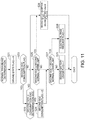
- FIG. 11 is a flow chart illustrating a specific procedure of a normal traveling determination process.
- FIG. 12 is a diagram schematically illustrating a range of a second SOC of the second battery which is realized when the driving state is a normal traveling state.
- FIG. 13 is a flow chart illustrating a specific procedure of a high-output traveling determination process.
- FIG. 14 is a diagram schematically illustrating ranges of a second SOC of the first battery and a second SOC of the second battery which are realized when the driving state is a high-output traveling state.
- FIG. 15 is a flow chart illustrating a specific procedure of a low-output traveling determination process.
- FIG. 16 is a diagram schematically illustrating a range of a second SOC of the second battery which is realized when the driving state is a low-output traveling state.
- FIG. 17A is a flow chart illustrating of a specific procedure of a regenerative traveling determination process.
- FIG. 17B is a flow chart illustrating of a specific procedure of the regenerative traveling determination process.
- FIG. 18 is a diagram schematically illustrating a range of a second SOC of the second battery which is realized when the driving state is a regenerative traveling state.
- FIG. 19 is a flow chart illustrating a specific procedure of an idle determination process.
- FIG. 20 is a diagram schematically illustrating a range of a second SOC of the second battery which is realized when the driving state is an idle state.
- FIG. 21 is a flow chart illustrating a specific procedure of a failure traveling determination process.
- FIG. 22 is a flow chart illustrating a specific procedure of an electrical pass determination process.
- FIG. 23 is a diagram illustrating ranges of a first SOC and a second SOC in which the execution of electrical pass control is permitted in the electrical pass determination process.
- FIG. 24 is a flow chart illustrating a specific procedure of a required motor torque arithmetic process of calculating a first required motor torque and a second required motor torque in a driving force distribution calculation unit.
- FIG. 25 is a functional block diagram illustrating a procedure of calculating required passage power in an energy distribution calculation unit.
- FIG. 26 is an example of a map for calculating a target power ratio on the basis of a second SOC.
- the disclosure provides a vehicle power supply system including at least two power storage devices and a motor generator which makes it possible to recover regenerative electric power generated in the motor generator with high power efficiency.
- a vehicle power supply system including: a first motor generator connected to a first wheel of a vehicle; a second motor generator connected to a second wheel; a first circuit to which a first power converter that transfers power to and from the first motor generator and a first power storage device are connected; a second circuit to which a second power converter that transfers power to and from the second motor generator and a second power storage device are connected; a voltage converter that converts a voltage between the first circuit and the second circuit; a charging and discharging control device that controls charging and discharging of the first and second power storage devices by operating the first and second power converters and the voltage converter; and a second regenerable electric power acquisition unit that acquires second regenerable electric power that is an upper limit for regenerative electric power supplied to the second power storage device during regenerative deceleration in which regenerative electric power is generated by the first and second motor generators, wherein the charging and discharging control device charges the second power storage device with second regenerative electric power that is power supplied
- a vehicle accessory that is an electrical load may be connected to the second circuit, and the charging and discharging control device may charge the second power storage device and drive the vehicle accessory with the second regenerative electric power, and set the second surplus regenerative electric power by excluding the second regenerable electric power and power required in the vehicle accessory from the second regenerative electric power.
- the first power storage device may be lower in output weight density and higher in energy weight density than the second power storage device.
- the first wheel may be a rear wheel and the second wheel is a front wheel
- the charging and discharging control device may operate the first and second power converters so that the second regenerative electric power become larger than first regenerative electric power that is power supplied from the first power converter to the first circuit during the regenerative deceleration.
- the vehicle power supply system may further include: a second power storage parameter acquisition unit that acquires a value of a second power storage parameter increasing in accordance with an amount of power storage of the second power storage device; and a second regeneration permission upper limit setting unit that sets a second regeneration permission upper limit that is a threshold for the second power storage parameter, and in a case where the value of the second power storage parameter is larger than the second regeneration permission upper limit during the regenerative deceleration, the charging and discharging control device may prohibit the second power storage device from being charged, and may supply at least a portion of the second regenerative electric power to the first power storage device through the voltage converter and the first circuit.
- the vehicle power supply system may further include: a second power storage parameter acquisition unit that acquires a value of a second power storage parameter increasing in accordance with an amount of power storage of the second power storage device; and a second regeneration permission upper limit setting unit that sets a second regeneration permission upper limit that is a threshold for the second power storage parameter, the charging and discharging control device may prohibit the second power storage device from being charged in a case where the value of the second power storage parameter is larger than the second regeneration permission upper limit during the regenerative deceleration, and that the second regeneration permission upper limit setting unit may change the second regeneration permission upper limit on the basis of a state of the first power storage device.
- the second regeneration permission upper limit setting unit may change the second regeneration permission upper limit on the basis of a state of the first power storage device.
- the vehicle power supply system may further include: a first power storage parameter acquisition unit that acquires a value of a first power storage parameter increasing in accordance with an amount of power storage of the first power storage device; and a first regeneration permission upper limit setting unit that sets a first regeneration permission upper limit that is a threshold for the first power storage parameter, in a case where the value of the first power storage parameter is larger than the first regeneration permission upper limit, the second regeneration permission upper limit setting unit may make the second regeneration permission upper limit larger than in a case where the value of the first power storage parameter is equal to or less than the first regeneration permission upper limit, and the charging and discharging control device may prohibit the first power storage device from being charged in a case where the value of the first power storage parameter is larger than the first regeneration permission upper limit during the regenerative deceleration.
- the second regeneration permission upper limit setting unit may set the second regeneration permission upper limit as a value of any of a predetermined first threshold and a second threshold larger than the first threshold, and the second regeneration permission upper limit setting unit may set the second regeneration permission upper limit as the first threshold in a case where the value of the second power storage parameter is equal to or less than the first threshold during the regenerative deceleration, and set the second regeneration permission upper limit as a value of any of the first threshold and the second threshold on the basis of the state of the first power storage device in a case where the value of the second power storage parameter is larger than the first threshold and equal to or less than the second threshold.
- the vehicle power supply system may further include a first regenerable electric power acquisition unit that acquires first regenerable electric power that is an upper limit for regenerative electric power supplied to the first power storage device during the regenerative deceleration, and the second regeneration permission upper limit setting unit may set the second regeneration permission upper limit as the second threshold in a case where the value of the second power storage parameter is larger than the first threshold and equal to or less than the second threshold during the regenerative deceleration, and required regenerative electric power is larger than the first regenerable electric power.
- the vehicle power supply system includes the first circuit to which the first power converter and the first power storage device are connected, the second circuit to which the second power converter and the second power storage device are connected, the voltage converter that convert a voltage between the first circuit and the second circuit, and the charging and discharging control device that controls charging and discharging of the first and second power storage devices by operating the first and second power converters and the voltage converter.
- the charging and discharging control device controls charging and discharging of the first and second power storage devices by operating the first and second power converters and the voltage converter.
- the charging and discharging control device charges the second power storage device with the second regenerative electric power supplied from the second power converter to the second circuit during regenerative deceleration, and supplies the second surplus regenerative electric power in which the second regenerable electric power is excluded from the second regenerative electric power to the first circuit through the voltage converter in a case where this second regenerative electric power is larger than the second regenerable electric power of the second power storage device. That is, in the vehicle power supply system, the second regenerative electric power supplied from the second power converter to the second circuit is used in charging of the second power storage device as much as possible. In a case where an excess portion that is not able to be consumed occurs in charging of the second power storage device, this excess portion is supplied to the first circuit through the voltage converter.
- the second surplus regenerative electric power supplied to the first circuit can be used in, for example, charging of the first power storage device.
- the vehicle power supply system since power that passes through the voltage converter during regenerative deceleration can be reduced as much as possible, it is possible to recover regenerative electric power supplied from the first and second power converters with high power efficiency.
- the vehicle accessory is connected to the second circuit.
- the vehicle accessory can be driven with second regenerative electric power supplied from the second power converter to the second circuit during regenerative deceleration.
- power in which the second regenerable electric power and required power in the vehicle accessory are excluded from the second regenerative electric power is defined as the second surplus regenerative electric power, and this second surplus regenerative electric power is supplied to the first circuit through the voltage converter. Therefore, according to the vehicle power supply system, since the second surplus regenerative electric power (that is, passage power of the voltage converter) can be further reduced by an amount required in the vehicle accessory, it is possible to further improve power efficiency.
- the second regenerative electric power supplied to the second circuit during regenerative deceleration is supplied to the second power storage device as much as possible. Therefore, in the vehicle power supply system, it can be said that the second power storage device is more likely to maintain the amount of power storage within a predetermined target range than the first power storage device.
- the first power storage device that is used is lower in output weight density and is higher in energy weight density than the second power storage device. That is, the first power storage device excellent in energy weight density is a capacity-type power storage device that is primarily intended for a high capacity, and the second power storage device excellent in output weight density is an output-type power storage device that is primarily intended for a high output.
- the second power storage device that is such an output type is often used so as to compensate for a shortage of this first power storage device in a case where power requested from a driver is not able to be covered by the first power storage device alone. For this reason, the amount of power storage of the second power storage device may be maintained within a predetermined target range in order to meet a driver's request at all times. Therefore, in the vehicle power supply system, the second power storage device is formed to have an output type, and thus the amount of power storage of the second power storage device can be maintained within a target range so as to meet a driver's request.
- the first wheel is defined as a rear wheel
- the second wheel is defined as a front wheel
- the charging and discharging control device operates the first and second power converters so that the second regenerative electric power becomes larger than the first regenerative electric power during regenerative deceleration, that is, a larger regenerative braking torque is imparted to the second wheel that is a front wheel than to the first wheel that is a rear wheel. Thereby, it is possible to stably brake a vehicle.
- the amount of power storage of the second power storage device can be likely to be maintained within a target range as described above.
- the charging and discharging control device charges the second power storage device with the second regenerative electric power.
- the second power storage device is prohibited from being charged, and at least a portion of the second regenerative electric power is supplied to the first power storage device through the voltage converter and the first circuit.
- the second regeneration permission upper limit is set with respect to the second power storage parameter of the second power storage device, and the second power storage device is prohibit from being charged in a case where the value of the second power storage parameter is larger than the second regeneration permission upper limit during regenerative deceleration.
- the second power storage device is prohibit from being charged in a case where the value of the second power storage parameter is larger than the second regeneration permission upper limit during regenerative deceleration.
- the second regeneration permission upper limit is set on the basis of the state of the first power storage device.
- the second regeneration permission upper limit is set as this first threshold, and in a case where the value of the second power storage parameter is larger than the first threshold and is equal to or less than the second threshold, the second regeneration permission upper limit is set as a value of any of the first threshold and the second threshold on the basis of the state of the first power storage device.
- the second regeneration permission upper limit is set as the second threshold.
- the vehicle accessory is connected to the second circuit, and this vehicle accessory is driven with the second regenerative electric power supplied from the second power converter to the second circuit during regenerative deceleration.
- the second regeneration permission upper limit is set as the second threshold.
- the second power storage device since the second power storage device is permitted to be charged, an excess portion that is not able to be recovered by the first power storage device and the vehicle accessory can be recovered by the second power storage device.
- the vehicle power supply system it is possible to recover regenerative electric power generated in the first and second motor generators with high power efficiency.
- FIG. 1 is a diagram illustrating a configuration of an electromotive vehicle V (hereinafter, simply referred to as a “vehicle”) in which a power supply system 1 according to the present embodiment is mounted.
- V electromotive vehicle
- the vehicle V includes a first wheel Wr, a second wheel Wf, a first drive motor Mr serving as a first motor generator connected to the first wheel Wr, a second drive motor Mf serving as a second motor generator connected to the second wheel Wf, the power supply system 1 that transfers power to and from these drive motors Mr and Mf, a first mechanical braking device Br provided in the first wheel Wr, a second mechanical braking device Bf provided in the second wheel Wf, and an electronic control unit 7 (hereinafter abbreviated as “ECU”) that controls the power supply system 1 , the drive motors Mr and Mf, and the mechanical braking devices Br and Bf.
- ECU electronice control unit 7
- the first wheel Wr is constituted by two wheels, that is, a left wheel and a right wheel.
- the second wheel Wf is constituted by two wheels, that is, a left wheel and a right wheel.
- the first wheel Wr is defined as a rear wheel provided on the rear side of the vehicle V in its traveling direction
- the second wheel Wf is defined as a front wheel provided on the front side of the vehicle V in its traveling direction
- the disclosure is not limited thereto.
- the first wheel Wr may be defined as a front wheel
- the second wheel Wf may be defined as a rear wheel.
- the vehicle V can travel in either drive mode of an all-wheel drive mode (hereinafter, also referred to as an “AWD mode”) and a two-wheel drive mode (hereinafter, also referred to as a “2WD mode”).
- AWD mode refers to a drive mode in which traveling is performed using both the first wheel Wr and the second wheel Wf as driving wheels
- 2WD mode refers to a drive mode in which traveling is performed using the first wheel Wr as a driving wheel and using the second wheel Wf as a driven wheel.
- the vehicle V basically travels in an AWD mode, and travels in a 2WD mode when predetermined conditions are established.
- a power saving driving request button BM 1 and a sports traveling request button BM 2 which can be operated by a driver are connected to the ECU 7 .
- the ECU 7 suppresses the consumption of power in the power supply system 1 by causing the vehicle V to travel with the drive mode preferentially set to a 2WD mode.
- the sports traveling request button BM 2 is pressed by a driver, the ECU 7 causes the vehicle V to travel with the drive mode preferentially set to an AWD mode.
- a driving state is a high-output traveling state
- power stored in a second battery B 2 to be described later is frequently used.
- the ECU 7 causes the vehicle V to travel in a recovery mode for quickly recovering the amount of power storage of the second battery B 2 so as to continuously respond to a high-output traveling request by a driver.
- the first drive motor Mr and the second drive motor Mf mainly generate motive power for causing the vehicle V to travel.
- the output shafts of the respective drive motors Mr and Mf are connected to the wheels Wr and Wf through a motive power transfer mechanism which is not shown.
- Torques generated in the drive motors Mr and Mf by supplying three-phase alternating-current power from the power supply system 1 to the drive motors Mr and Mf are transferred to the wheels Wr and Wf through the motive power transfer mechanism which is not shown, to rotate the wheels Wr and Wf and cause the vehicle V to travel.
- the drive motors Mr and Mf generate regenerative electric power by acting as generators during deceleration of the vehicle V, and impart a regenerative braking torque according to the magnitude of this regenerative electric power to the wheels Wr and Wf.
- the regenerative electric power generated by the drive motors Mr and Mf is used to charge a first battery B 1 and the second battery B 2 to be described later which are included in the power supply system 1 .
- the first mechanical braking device Br and the second mechanical braking device Bf are constituted by a disc braking system that imparts mechanical braking torques based on friction to the first wheel Wr and the second wheel Wf.
- the ECU 7 sets targets for braking torques which are imparted from the mechanical braking devices Br and Bf to the wheels Wr and Wf by performing a cooperative control process of causing regenerative braking torques imparted from the drive motors Mr and Mf to the wheels Wr and Wf and mechanical braking torques imparted from the mechanical braking devices Br and Bf to the wheels Wr and Wf to cooperate with each other.
- the mechanical braking devices Bf and Br impart the mechanical braking torques according to the targets determined by this cooperative control process to the wheels Wr and Wf, and decelerate the vehicle V.
- the power supply system 1 includes the first battery B 1 serving as a first power storage device, the second battery B 2 serving as a second power storage device, a vehicle accessory H serving as an electrical load that consumes power, and a power circuit 2 that connects these batteries B 1 and B 2 and the drive motors Mr and Mf.
- the first battery B 1 is a secondary battery in which both discharging in which chemical energy is converted into electrical energy and charging in which electrical energy is converted into chemical energy are possible.
- a so-called lithium-ion storage battery that performs charging and discharging by lithium ions moving between electrodes is used as this first battery B 1 will be described, but the disclosure is not limited thereto.
- the first battery B 1 is provided with a first battery sensor unit 81 in order to estimate the internal state of the first battery B 1 .
- the first battery sensor unit 81 is constituted by a plurality of sensors that detect physical quantities required for acquiring the charging rate, a temperature or the like of the first battery B 1 in the ECU 7 and transmit signals according to detection values to the ECU 7 . More specifically, the first battery sensor unit 81 is constituted by a voltage sensor that detects the terminal voltage of the first battery B 1 , a current sensor that detects a current flowing through the first battery B 1 , a temperature sensor that detects the temperature of the first battery B 1 , and the like.
- the ECU 7 calculates a first power storage parameter increasing in accordance with the amount of power storage of the first battery B 1 , more specifically, a charging rate at which the amount of power storage of the first battery B 1 is expressed in a percentage, on the basis of a known algorithm using detection values transmitted from the first battery sensor unit 81 .
- the charging rate of the first battery B 1 calculated in the ECU 7 using signals transmitted from the first battery sensor unit 81 is referred to as a first state of charge (SOC).
- the second battery B 2 is a secondary battery in which both discharging in which chemical energy is converted into electrical energy and charging in which electrical energy is converted into chemical energy are possible.
- a so-called lithium-ion storage battery that performs charging and discharging by lithium ions moving between electrodes is used as this second battery B 2 will be described, but the disclosure is not limited thereto.
- a capacitor may be used as the second battery B 2 .
- the second battery B 2 is provided with a second battery sensor unit 82 in order to estimate the internal state of the second battery B 2 .
- the second battery sensor unit 82 is constituted by a plurality of sensors that detect physical quantities required for acquiring the charging rate, a temperature or the like of the second battery B 2 in the ECU 7 and transmit signals according to detection values to the ECU 7 . More specifically, the second battery sensor unit 82 is constituted by a voltage sensor that detects the terminal voltage of the second battery B 2 , a current sensor that detects a current flowing through the second battery B 2 , a temperature sensor that detects the temperature of the second battery B 2 , and the like.
- the ECU 7 calculates a second power storage parameter increasing in accordance with the amount of power storage of the second battery B 2 , more specifically, a charging rate at which the amount of power storage of the second battery B 2 is expressed in a percentage, on the basis of a known algorithm using detection values transmitted from the second battery sensor unit 82 .
- the charging rate of the second battery B 2 calculated in the ECU 7 using signals transmitted from the second battery sensor unit 82 is referred to as a second SOC.
- the characteristics of the first battery B 1 and the characteristics of the second battery B 2 will be compared with each other.
- the full charging state voltage of the first battery B 1 is higher than the full charging state voltage of the second battery B 2 . Therefore, during traveling of the vehicle V, the voltage of a first power line 21 to be described later to which the first battery B 1 is directly connected is higher than the voltage of a second power line 22 to which the second battery B 2 is directly connected.
- the first battery B 1 is lower in output weight density and is higher in energy weight density than the second battery B 2 .
- the first battery B 1 has a larger capacity than the second battery B 2 . That is, the first battery B 1 has more excellent energy weight density than the second battery B 2 .
- the second battery B 2 has more excellent output weight density than the first battery B 1 .
- the energy weight density is the amount of power per unit weight [Wh/kg]
- the output weight density is power per unit weight [W/kg]. Therefore, the first battery B 1 that has excellent energy weight density is a capacity-type power storage device that is primarily intended for a high capacity, and the second battery B 2 that has excellent output weight density is an output-type power storage device that is primarily intended for a high output. Therefore, in the power supply system 1 , the first battery B 1 is used as a main power supply, and the second battery B 2 is used as a sub power supply that makes up for the first battery B 1 that is the main power supply.
- FIG. 2 is a diagram illustrating ranges of use of the first battery B 1 and the second battery B 2 .
- the left side of FIG. 2 represents a range of use of the first SOC of the first battery B 1
- the right side thereof represents a range of use of the second SOC of the second battery B 2 .
- a first usable upper limit and a second usable upper limit are both set at positions slightly lower than 100%. That is, in a case where the first SOC becomes higher than the first usable upper limit, there may be a concern of the first battery B 1 deteriorating. In addition, in a case where the second SOC becomes higher than the second usable upper limit, there may be a concern of the second battery B 2 deteriorating.
- a first usable lower limit and a second usable lower limit are both set at positions slightly higher than 0%. That is, in a case where the first SOC is set to be equal to or less than the first usable lower limit, there may be a concern of required power not being able to be output from the first battery B 1 . In addition, in a case where the second SOC is set to be equal to or less than the second usable lower limit, there may be a concern of required power not being able to be output from the second battery B 2 .
- the first battery B 1 is prohibited from being discharged in a case where the first SOC is equal to or less than the first usable lower limit
- the second battery B 2 is prohibited from being discharged in a case where the second SOC is equal to or less than the second usable lower limit.
- the usable range of the first battery B 1 is between the first usable upper limit and the first usable lower limit
- the usable range of the second battery B 2 is between the second usable upper limit and the second usable lower limit
- the power circuit 2 includes a first inverter 3 r that transfers power to and from the first drive motor Mr, a first power line 21 serving as a first circuit that connects the DC input and output terminal of this first inverter 3 r and the first battery B 1 , a second inverter 3 f that transfers power to and from the second drive motor Mf, a second power line 22 that connects the DC input and output terminal of this second inverter 3 f , the second battery B 2 and the vehicle accessory H, and a voltage converter 4 that connects the first power line 21 and the second power line 22 .
- the first inverter 3 r and the second inverter 3 f are, for example, PWM inverters based on pulse width modulation including a bridge circuit configured to bridge-connect a plurality of switching elements (for example, IGBTs), and have a function of converting direct-current power and alternating-current power.
- the first inverter 3 r is connected to the first power line 21 on its DC input and output side, and is connected to each coil of the U-phase, V-phase, and W-phase of the first drive motor Mr on its AC input and output side.
- the second inverter 3 f is connected to the second power line 22 on its DC input and output side, and is connected to each coil of the U-phase, V-phase, and W-phase of the second drive motor Mf on its AC input and output side.
- the inverters 3 r and 3 f drive on/off of a switching element of each phase in accordance with a gate drive signal generated at a predetermined timing from a gate drive circuit (not shown) of the ECU 7 , to thereby convert direct-current power in the power lines 21 and 22 into three-phase alternating-current power and supply the converted power to the drive motors Mr and Mf, or to convert three-phase alternating-current power supplied from the drive motors Mr and Mf into direct-current power and supply the converted power to the power lines 21 and 22 .
- the voltage converter 4 connects the first power line 21 and the second power line 22 , and converts a voltage between the first power line 21 and the second power line 22 .
- the voltage converter 4 is a so-called bidirectional DCDC converter which is configured to combine a reactor, a smoothing capacitor, a plurality of switching elements (for example, IGBTs), and the like, and converts a direct-current voltage between the first power line 21 and the second power line 22 .
- the voltage converter 4 drives on/off of the plurality of switching elements in accordance with a gate drive signal generated at a predetermined timing from a gate drive circuit (not shown) of the ECU 7 , to thereby convert a voltage between the first power line 21 and the second power line 22 .
- the full charging state voltage of the first battery B 1 is higher than the full charging state voltage of the second battery B 2 . Therefore, basically, the voltage of the first power line 21 is higher than the voltage of the second power line 22 . Consequently, in a case where power in the first power line 21 is supplied to the second power line 22 , the ECU 7 drives the voltage converter 4 , and exhibits a stepping-down function.
- the term “stepping-down function” refers to a function of stepping down power in the first power line 21 which is a high-voltage side, outputting the stepped-down power to the second power line 22 , and causing a current to flow from the first power line 21 side to the second power line 22 side.
- the ECU 7 drives the voltage converter 4 , and exhibits a boosting function.
- the term “boosting function” refers to a function of boosting power in the second power line 22 which is a low-voltage side, outputting the boosted power to the first power line 21 , and causing a current to flow from the second power line 22 side to the first power line 21 side.
- the vehicle accessory H is constituted by, for example, a battery heater that heats the first battery B 1 , an air conditioner that regulates the temperature of a vehicle interior (not shown), a DCDC converter that charges an auxiliary battery (not shown), and the like.
- the ECU 7 is a microcomputer, and controls charging and discharging of the batteries B 1 and B 2 and a flow of power in the power lines 21 and 22 and the voltage converter 4 by operating the inverters 3 r and 3 f , the voltage converter 4 , the mechanical braking devices Br and Bf, and the like during traveling of the vehicle V.
- the inverters 3 r and 3 f the voltage converter 4
- the mechanical braking devices Br and Bf and the like during traveling of the vehicle V.
- FIG. 3 is a diagram illustrating portions relating to the execution of energy management control among a plurality of control modules configured in the ECU 7 .
- the ECU 7 includes a required power calculation unit 70 that calculates various types of required power, a driving state determination unit 71 that mainly executes a process relating to the determination of the driving state of the vehicle V, an inverter control unit 72 that mainly executes a process relating to torque distribution by the drive motors Mr and Mf using a determination result of the driving state determination unit 71 or the like and controls the first inverter 3 r and the second inverter 3 f using this process result, a voltage converter control unit 73 that mainly executes a process relating to of the rate of share of charging and discharging of the batteries B 1 and B 2 using the determination result of the driving state determination unit 71 or the like and controls the voltage converter 4 using this process result, a first mechanical braking control unit 74 r and a second mechanical braking control unit 74 f that control the mechanical braking devices Br and Bf using a result of the process relating to torque distribution in the inverter control unit 72 , and a regeneration determination unit 75 .
- the required power calculation unit 70 calculates required power which is power that is required in various types of devices mounted in the vehicle V. Examples of the required power calculated in the required power calculation unit 70 include vehicle required power and total required power.
- the vehicle required power is power required in devices required for driving the vehicle V, more specifically, the first drive motor Mr and the second drive motor Mf.
- the required power calculation unit 70 calculates a required driving force of the vehicle V on the basis of a detection value of an accelerator pedal position sensor that detects the position of an accelerator pedal (not shown) and a detection value of a brake pedal position sensor that detects the position of a brake pedal (not shown), and calculates the vehicle required power on the basis of this required driving force.
- This vehicle required power is set to be positive during power operations of the drive motors Mr and Mf, and is set to be negative during regenerative operations of the drive motors Mr and Mf.
- the total required power is power required in the first power line 21 and the second power line 22 of the power supply system 1 .
- the required power calculation unit 70 calculates accessory required power which is required power in the vehicle accessory H, and calculates the total required power by adding this accessory required power to the vehicle required power.
- the regeneration determination unit 75 updates the value of a regeneration flag.
- the regeneration flag is a flag that clarifies a state in which regenerative traveling where regenerative braking torques are imparted from the drive motors Mr and Mf to the wheels Wr and Wf is possible, and can take on a value of “0” or “1.”
- a value of “0” for the regeneration flag indicates a state in which regenerative traveling is not possible, and a value of “1” for the regeneration flag indicates a state in which regenerative traveling is possible.
- the regeneration determination unit 75 updates the value of the regeneration flag on the basis of the detection value of the accelerator pedal position sensor, the brake pedal position sensor, or the like described above.
- the driving state determination unit 71 updates values of various types of flags indicating the driving state of the vehicle V, the usage states of the batteries B 1 and B 2 , or the like, in accordance with procedures to be described later with reference to FIGS. 10 to 23 , on the basis of required power calculated in the required power calculation unit 70 , a regeneration flag updated in the regeneration determination unit 75 , and various inputs such as the first SOC and the second SOC calculated on the basis of the detection signals of the battery sensor units 81 and 82 .
- Examples of flags of which the values are updated in the driving state determination unit 71 include a driving state flag, a first battery usage flag, a second battery usage flag, a second SOC consumption request flag, an electrical pass execution flag, a voltage converter deactivation request flag, a first battery failure flag, and a second battery failure flag.
- the driving state flag is a flag that clarifies the current driving state of the vehicle V, and can take on a value of any of “0,” “1,” “2,” “3,” “4,” and “5.”
- six driving states that is, a “normal traveling state,” a “high-output traveling state,” a “low-output traveling state,” a “regenerative traveling state,” an “idle state,” and a “failure traveling state” are defined as the driving states of the vehicle V.
- a value of “0” for the driving state flag indicates that the driving state is the normal traveling state.
- a value of “1” for the driving state flag indicates that the driving state is the high-output traveling state.
- a value of “2” for the driving state flag indicates that the driving state is the low-output traveling state.
- a value of “3” for the driving state flag indicates that the driving state is the regenerative traveling state.
- a value of “4” for the driving state flag indicates that the driving state is the idle state.
- a value of “5” for the driving state flag indicates that the driving state is the failure traveling state.
- the first battery usage flag is a flag that clarifies the usage state of the first battery B 1 , and can take on a value of any of “0,” “1,” and “2.”
- a value of “0” for the first battery usage flag indicates that charging and discharge of the first battery B 1 , that is, both the supply of power to the first battery B 1 and the supply of power from the first battery B 1 to a load, are permitted.
- a value of “1” for the first battery usage flag indicates a state in which the first battery B 1 is prohibited from being discharged.
- a value of “2” for the first battery usage flag indicates that the first battery B 1 is prohibited from being charged.
- the second battery usage flag is a flag that clarifies the usage state of the second battery B 2 , and can take on a value of any of “0,” “1,” and “2.”
- a value of “0” for the second battery usage flag indicates that charging and discharge of the second battery B 2 , that is, both the supply of power to the second battery B 2 and the supply of power from the second battery B 2 to a load, are permitted.
- a value of “1” for the second battery usage flag indicates a state in which the second battery B 2 is prohibited from being discharged.
- a value of “2” for the second battery usage flag indicates that the second battery B 2 is prohibited from being charged.
- the second SOC consumption flag is a flag that clarifies a state in which the second SOC of the second battery B 2 is close to the second usable upper limit, that is, a state in which the consumption of the second SOC is required, and can take on a value of any of “0” and “1.”
- a value of “0” for the second SOC consumption flag indicates a state in which the consumption of the second SOC is not required.
- a value of “1” for the second SOC consumption flag indicates a state in which the consumption of the second SOC is required.
- the electrical pass execution flag is a flag that clarifies a state in which power discharged from the first battery B 1 is supplied to the second battery B 2 and electrical pass control for charging the second battery B 2 is executed, and can take on a value of any of “0,” “1,” and “2.”
- a value of “0” for the electrical pass execution flag indicates a state in which electrical pass control is not executed.
- a value of “1” for the electrical pass execution flag indicates a state in which electrical pass control is executed.
- a value of “2” for the electrical pass execution flag indicates a state in which the execution of electrical pass control is interrupted (that is, a state in which the execution of electrical pass control is temporarily prohibited).
- the voltage converter deactivation request flag is a flag that clarifies a state in which the deactivation of the voltage converter 4 is required in order to reduce a loss occurring in the voltage converter 4 , and can take on a value of any of “0” and “1.”
- a value of “0” for the voltage converter deactivation request flag indicates a state in which the deactivation of the voltage converter 4 is not required, and a value of “1” for the voltage converter deactivation request flag indicates a state in which the deactivation of the voltage converter 4 is required.
- the first battery failure flag is a flag that clarifies a state in which the first battery B 1 is out of order, and can take on a value of any of “0” and “1.”
- a value of “0” for the first battery failure flag indicates that the first battery B 1 is normal and is in a usable state.
- a value of “1” for the first battery failure flag indicates that the first battery B 1 is out of order and is in an unusable state.
- the second battery failure flag is a flag that clarifies a state in which the second battery B 2 is out of order, and can take on a value of any of “0” and “1.”
- a value of “0” for the second battery failure flag indicates that the second battery B 2 is normal and is in a usable state.
- a value of “1” for the second battery failure flag indicates that the second battery B 2 is out of order and is in an unusable state.
- FIGS. 4A to 4C are diagrams schematically illustrating flows of power realized in the power supply system 1 when the driving state is the normal traveling state. More specifically, FIG. 4A shows a flow of power realized in a case where the value of the driving state flag is “0” and the value of the second battery usage flag is “1,” and FIG. 4B shows a flow of power realized in a case where the value of the driving state flag is “0” and the value of the electrical pass execution flag is “1.” FIG. 4C shows a flow of power realized in a case where the value of the driving state flag is “0,” the value of the second battery usage flag is “0,” and the value of the second SOC consumption flag is “1.”
- the power supply system 1 supplies power to both the first drive motor Mr and the second drive motor Mf, and performs traveling using the first wheel Wr and the second wheel Wf as driving wheels. That is, in a case where the driving state is the normal traveling state, the drive mode of the vehicle V is an AWD mode.
- the driving state is the normal traveling state
- discharging from the second battery B 2 to the second power line 22 is prohibited. Therefore, all power required in the first drive motor Mr, the second drive motor Mf, and the vehicle accessory H is covered by power discharged from the first battery B 1 . That is, a portion of power that is discharged from the first battery B 1 to the first power line 21 is supplied to the second power line 22 through the voltage converter 4 , and is consumed in the second drive motor Mf and the vehicle accessory H.
- FIG. 5 is a diagram schematically illustrating a flow of power realized in the power supply system 1 when the driving state is the high-output traveling state. More specifically, FIG. 5 shows a flow of power realized in a case where the value of the driving state flag is “1” and the value of the second battery usage flag is “0.”
- the power supply system 1 supplies power to both the first drive motor Mr and the second drive motor Mf, and performs traveling using the first wheel Wr and the second wheel Wf as driving wheels. That is, in a case where the driving state is the high-output traveling state, the drive mode of the vehicle V is an AWD mode.
- the total required power which is power required in the power lines 21 and 22 is larger than in the normal traveling state described with reference to FIGS. 4A to 4C .
- the driving state is the high-output traveling state
- power is discharged from the second battery B 2 to the second power line 22 , and is consumed in the second drive motor Mf and the vehicle accessory H.
- a shortage of power which is not covered by the first battery B 1 alone in the total required power is compensated for by the second battery B 2 .
- FIGS. 6A and 6B are diagrams schematically illustrating flows of power realized in the power supply system 1 when the driving state is the low-output traveling state. More specifically, FIG. 6A shows a flow of power realized in a case where the value of the driving state flag is “2,” the value of the second battery usage flag is “0,” and the value of the voltage converter deactivation request flag is “1,” and FIG. 6B shows a flow of power realized in a case where the value of the driving state flag is “2,” the value of the voltage converter deactivation request flag is “0,” and the value of the electrical pass execution flag is “1.”
- the power supply system 1 supplies required power to the first drive motor Mr, performs traveling using the first wheel Wr as a driving wheel, and supplies only power required for performing zero torque control in which the first wheel Wr is followed by the second wheel Wf with a drive torque set to 0 to the second drive motor Mf. That is, in a case where the driving state is the low-output traveling state, the drive mode of the vehicle V is a 2WD mode.
- the power required in the second power line 22 is only power required for maintaining the drive torque of the second drive motor Mf at 0 and power required in the vehicle accessory H, and is less than that in the normal traveling state or the high-output traveling state described above. Therefore, in the low-output traveling state, the power that is required in the second power line 22 can be covered by power discharged from the second battery B 2 alone. Consequently, as shown in FIG. 6A , in a case where the driving state is the low-output traveling state, basically, discharging from the second battery B 2 to the second power line 22 is permitted, and the power required for performing zero torque control on the second drive motor Mf and the power required in the vehicle accessory H are covered by the second battery B 2 alone.
- FIGS. 7A to 7E are diagrams schematically illustrating flows of power realized in the power supply system 1 when the driving state is a regenerative traveling state. More specifically, FIG. 7A shows a flow of power realized in a case where the value of the driving state flag is “3” and both the values of the first battery usage flag and the second battery usage flag are “0,” FIG. 7B shows a flow of power realized in a case where the value of the driving state flag is “3,” the value of the first battery usage flag is “0,” and the value of the second battery usage flag is “2,” FIG.
- FIG. 7C shows a flow of power realized in a case where the value of the driving state flag is “3,” the value of the first battery usage flag is “2,” and the value of the second battery usage flag is “0”
- FIG. 7D shows a flow of power realized in a case where the value of the driving state flag is “3” and both the values of the first battery usage flag and the second battery usage flag are “2”
- FIG. 7E shows a flow of power realized in a case where the value of the driving state flag is “3” and the value of the electrical pass execution flag is “1.”
- the drive mode is set as an AWD mode so that as much regenerative electric power as possible can be recovered by the batteries B 1 and B 2 and that losses in the mechanical braking devices Br and Bf can be reduced. Therefore, in a case where the driving state is a regenerative traveling state, as shown in FIGS. 7A to 7C and 7E , regenerative electric power is generated in the first drive motor Mr and the second drive motor Mf, and is supplied to the first power line 21 and the second power line 22 .
- regenerative electric power that is supplied from the first drive motor Mr to the first power line 21 is consumed in charging of the first battery B 1
- regenerative electric power that is supplied from the second drive motor Mf to the second power line 22 is consumed in charging of the second battery B 2 and driving of the vehicle accessory H.
- a regenerative braking torque imparted to the second wheel that is a front wheel during regenerative deceleration is larger than a regenerative braking torque imparted to the first wheel that is a rear wheel.
- the regenerative electric power that is supplied from the second drive motor Mf to the second power line 22 is larger than the regenerative electric power that is supplied from the first drive motor Mr to the first power line 21 . Therefore, an excess portion that is not able to be consumed in the second battery B 2 and the vehicle accessory H in the regenerative electric power supplied to the second power line 22 is supplied to the first battery B 1 through the voltage converter 4 .
- the driving state is a regenerative traveling state
- the value of the first battery usage flag is “0,” and the value of the second battery usage flag is “2,” the second battery B 2 is prohibited from being charged.
- a portion that is not able to be consumed in the vehicle accessory H in regenerative electric power in the second power line 22 is supplied to the first power line 21 through the voltage converter 4 , and is consumed in charging of the first battery B 1 .
- passage power of the voltage converter 4 further increases than that in the example of FIG. 7A to the extent that the second battery B 2 is prohibited from being charged in the example of FIG. 7B .
- a loss in the voltage converter 4 is larger than that in the example of FIG. 7A .
- the driving state is a regenerative traveling state
- the value of the first battery usage flag is “2,” and the value of the second battery usage flag is “0,” the first battery B 1 is prohibited from being charged. Therefore, the regenerative electric power that is supplied from the first drive motor Mr to the first power line 21 is supplied to the second power line 22 through the voltage converter 4 .
- the regenerative electric power in the second power line 22 is consumed in charging of the second battery B 2 and driving of the vehicle accessory H.
- the driving state is a regenerative traveling state and both values of the first battery usage flag and the second battery usage flag are “2,” the first battery B 1 and the second battery B 2 are prohibited from being charged.
- the regenerative electric power that is supplied from the drive motors Mr and Mf to the power lines 21 and 22 is set to be 0.
- the regenerative braking torques that are imparted from the drive motors Mr and Mf to the wheels Wr and Wf are also set to be 0.
- mechanical braking torques that are imparted from the mechanical braking devices Br and Bf to the wheels Wr and Wf increase, and thereby a deceleration operation as required is realized.
- the driving state is a regenerative traveling state and the value of the electrical pass execution flag is set to “1”
- the regenerative electric power that is supplied from the first drive motor Mr to the first power line 21 and the power that is discharged from the first battery B 1 to the first power line 21 are supplied to the second power line 22 through the voltage converter 4 .
- the regenerative electric power that is supplied from the second drive motor Mf to the second power line 22 and the power that is supplied from the voltage converter 4 to the second power line 22 are consumed in charging of the second battery B 2 and driving of the vehicle accessory H.
- FIGS. 8A and 8B are diagrams schematically illustrating flows of power realized in the power supply system 1 when the driving state is an idle state. More specifically, FIG. 8A shows a flow of power realized in a case where the value of the driving state flag is “4” and the value of the second battery usage flag is “0,” and FIG. 8B shows a flow of power realized in a case where the value of the driving state flag is “4” and the value of the second battery usage flag is “1.”
- the power supply system 1 stops the supply of power to the drive motors Mr and Mf, and supplies power to only the vehicle accessory H.
- the driving state is an idle state
- discharging from the second battery B 2 to the second power line 22 is permitted, and power required in the vehicle accessory H is covered by the second battery B 2 .
- the voltage converter 4 is deactivated as shown in FIG. 8A and a flow of power between the first power line 21 and the second power line 22 can be interrupted, a loss in the voltage converter 4 can be reduced to 0.
- FIGS. 9A and 9B are diagrams schematically illustrating flows of power realized in the power supply system 1 when the driving state is a failure traveling state. More specifically, FIG. 9A shows a flow of power realized in a case where the value of the driving state flag is “5” and the value of the second battery failure flag is “1,” and FIG. 9B shows a flow of power realized in a case where the value of the driving state flag is “5” and the value of the first battery failure flag is “1.”
- the inverter control unit 72 includes a driving force distribution calculation unit 721 , a first gate drive circuit 722 , and a second gate drive circuit 723 , and controls the first inverter 3 r and the second inverter 3 f by using these components.
- the driving force distribution calculation unit 721 calculates a first required motor torque for first drive motor Mr and a second required motor torque for the second drive motor Mf so that the flows of power shown in FIG. 4A to FIG. 9B are realized on the basis of required power calculated by the required power calculation unit 70 , a regeneration flag updated by the regeneration determination unit 75 , battery composition limit power (described later) calculated in the voltage converter control unit 73 , various types of flags updated by the driving state determination unit 71 , and the like.
- the first required motor torque and the second required motor torque are set to be positive during power operations of the drive motors Mr and Mf, and are set to be negative during regenerative operations of the drive motors Mr and Mf. Meanwhile, a specific arithmetic procedure in this driving force distribution calculation unit 721 will be described later with reference to FIG. 24 .
- the first gate drive circuit 722 performs switching control on the first inverter 3 r in accordance with the first required motor torque calculated in the driving force distribution calculation unit 721 . Thereby, a drive torque (in a case where the first required motor torque is positive) or a regenerative braking torque (in a case where the first required motor torque is negative) having a magnitude according to the first required motor torque is imparted from the first drive motor Mr to the first wheel Wr.
- the second gate drive circuit 723 performs switching control on the second inverter 3 f in accordance with the second required motor torque calculated in the driving force distribution calculation unit 721 . Thereby, a drive torque (in a case where the second required motor torque is positive) or regenerative braking torque (in a case where the second required motor torque is negative) having a magnitude according to the second required motor torque is imparted from the second drive motor Mf to the second wheel Wf.
- the first mechanical braking control unit 74 r calculates a first target braking torque equivalent to a target for a braking torque that is imparted to the first wheel Wr during deceleration of the vehicle V, calculates a first target mechanical braking torque by subtracting the first required motor torque calculated by the driving force distribution calculation unit 721 from this first target braking torque, and inputs the calculated torques to the first mechanical braking device Br.
- the first target braking torque is calculated on the basis of the vehicle required power calculated in the required power calculation unit 70 .
- the second mechanical braking control unit 74 f calculates a second target braking torque equivalent to a target for a braking torque that is imparted to the second wheel Wf during deceleration of the vehicle V, calculates a second target mechanical braking torque by subtracting the second required motor torque calculated by the driving force distribution calculation unit 721 from this second target braking torque, and inputs the calculated torques to the second mechanical braking device Bf.
- the second target braking torque is calculated on the basis of the vehicle required power calculated in the required power calculation unit 70 .
- the voltage converter control unit 73 includes a composition limit power calculation unit 731 , an energy distribution calculation unit 732 , and a gate drive circuit 733 , and controls the voltage converter 4 by using these components.
- the energy distribution calculation unit 732 calculate required passage power for power that passes through the voltage converter 4 so that the flows of power shown in FIGS. 4A to 9B are realized on the basis of required power calculated in the required power calculation unit 70 , a regeneration flag updated in the regeneration determination unit 75 , various types of flags updated in the driving state determination unit 71 , and the like.
- This required passage power is set to be positive, for example, with respect to the first power line 21 side to the second power line 22 side. Meanwhile, a specific arithmetic procedure in this energy distribution calculation unit 732 will be described later with reference to FIG. 25 .
- the gate drive circuit 733 converts the required passage power calculated by the energy distribution calculation unit 732 into a target for a current flowing through the voltage converter 4 from the first power line 21 side to the second power line 22 side, and performs switching control on the voltage converter 4 so that this target is realized.
- FIG. 10 is a main flow chart of a driving state determination process in the driving state determination unit 71 .
- the driving state determination process of FIG. 10 is repeatedly executed in a predetermined control period in the driving state determination unit 71 until a start button (not shown) for starting up the vehicle V is turned on by a driver and then this start button is turned off.
- the driving state determination unit 71 determines whether the batteries B 1 and B 2 are normal on the basis of signals transmitted from the battery sensor units 81 and 82 .
- the driving state determination unit 71 proceeds to S 2 in a case where the determination result of S 1 is YES, proceeds to S 13 in a case of the determination result is NO, and executes a failure traveling determination process to be described later with reference to FIG. 21 .
- the driving state determination unit 71 determines whether the vehicle V is stopping on the basis of a signal transmitted from a vehicle speed sensor (not shown) that detects a vehicle speed that is a speed of the vehicle V.
- the driving state determination unit 71 proceeds to S 3 in a case where the determination result of S 2 is NO, proceeds to S 12 in a case where the determination result is YES, and executes an idle determination process to be described later with reference to FIG. 19 .
- the driving state determination unit 71 determines whether the value of the regeneration flag is “1.” The driving state determination unit 71 proceeds to S 4 in a case where the determination result of S 3 is NO, proceeds to S 11 in a case where the determination result is YES, and executes a regenerative traveling determination process to be described later with reference to FIGS. 17A and 17B .
- the driving state determination unit 71 determines whether the power saving driving request button BM 1 is pressed. The driving state determination unit 71 proceeds to S 5 in a case where the determination result of S 4 is YES, and proceeds to S 6 in a case where the determination result is NO. In S 5 , the driving state determination unit 71 determines whether the vehicle V is in a cruise state.
- the driving state determination unit 71 determines whether the vehicle V is in a cruise state by determining whether the required driving force is equal to or less than a predetermined driving force using a signal transmitted from an accelerator pedal position sensor, a signal transmitted from a front-rear acceleration sensor (not shown) that detects front-rear acceleration of the vehicle V, required motor torques for the drive motors Mr and Mf, and the like.
- the driving state determination unit 71 proceeds to S 6 in a case where the determination result of S 5 is NO, proceeds to S 10 in a case where the determination result is YES, and executes a low-output traveling determination process to be described later with reference to FIG. 15 .
- the driving state determination unit 71 calculates first outputtable power which is an upper limit of power capable of being output from the first battery B 1 , and proceeds to S 7 .
- the driving state determination unit 71 calculates the first outputtable power on the basis of, for example, a signal transmitted from the first battery sensor unit 81 .
- the driving state determination unit 71 determines whether the total required power is larger than the first outputtable power, that is, all power required in the first power line 21 and the second power line 22 can be covered by the first battery B 1 .
- the driving state determination unit 71 proceeds to S 8 in a case where the determination result of S 7 is NO, and executes a normal traveling determination process to be described later with reference to FIG. 11 .
- the driving state determination unit 71 proceeds to S 9 in a case where the determination result of S 7 is YES, and executes a high-output traveling determination process to be described later with reference to FIG. 13 .
- FIG. 11 is a flow chart illustrating a specific procedure of a normal traveling determination process.
- FIG. 12 is a diagram schematically illustrating a range of the second SOC of the second battery B 2 which is realized when the driving state is a normal traveling state.
- the driving state determination unit 71 sets the value of the driving state flag to “0” so as to clarify that the current driving state of the vehicle V is a normal traveling state, and proceeds to S 22 .
- the driving state determination unit 71 determines whether the value of the second SOC consumption flag is “1.” The driving state determination unit 71 proceeds to S 23 in a case where the determination result of S 22 is YES, and proceeds to S 25 in a case where the determination result is NO. This second SOC consumption flag is set to “1” in S 26 to be described later, and then is reset to “0” in accordance with whether the process of S 24 to be described later is executed or a change in the value of the driving state flag from “0” to another value.
- the driving state determination unit 71 determines whether the current second SOC of the second battery B 2 is equal to or greater than a second normal upper limit determined in advance.
- This second normal upper limit is a threshold for the second SOC, and is set to be slightly lower than the second usable upper limit at which the supply of regenerative electric power to the second battery B 2 is entirely prohibited as shown in FIG. 12 .
- the driving state determination unit 71 proceeds to S 26 in a case where the determination result of S 25 is YES, and proceeds to S 27 in a case where the determination result is NO.
- the driving state determination unit 71 sets the value of the second SOC consumption flag to “1” and sets the value of the second battery usage flag to “0” so as to secure room for receiving regenerative electric power in the second battery B 2 , and terminates the normal traveling determination process of FIG. 11 .
- the driving state determination unit 71 determines whether the second SOC is equal to or less than a consumption end determination SOC determined in advance.
- This consumption end determination SOC is a threshold for the second SOC, and is set to be slightly lower than the second normal upper limit as shown in FIG. 12 .
- the driving state determination unit 71 proceeds to S 26 so as to continuously promote the consumption of the second SOC.
- the driving state determination unit 71 determines that room for the second battery B 2 to receive regenerative electric power is secured, proceeds to S 24 , resets the value of the second SOC consumption flag to “0,” and then proceeds to S 27 .
- the driving state determination unit 71 determines whether the second SOC is lower than a second normal lower limit determined in advance.
- This second normal lower limit is a threshold for the second SOC, and is set between the consumption end determination SOC and the second usable lower limit as shown in FIG. 12 .
- the driving state determination unit 71 proceeds to S 28 in a case where the determination result of S 27 is YES, and proceeds to S 29 in a case where the determination result is NO.
- the driving state determination unit 71 sets the value of the electrical pass request flag to “1” so as to promote the recovery of the second SOC of the second battery B 2 , and then terminates the normal traveling determination process of FIG. 11 .
- This electrical pass request flag is a flag that clarifies a state in which the execution of electrical pass control described above is required, and can take on a value of any of “0” and “1.”
- a value of “0” for the electrical pass request flag indicates a state in which the execution of electrical pass control is not required, and a value of “1” for the electrical pass request flag indicates a state in which the execution of electrical pass control is required. Therefore, in accordance with the value of the electrical pass request flag being set to “1” in S 28 , as will be described later with reference to FIG. 22 , an electrical pass determination process of determining whether or not to execute the electrical pass control is executed.
- the driving state determination unit 71 sets the value of the second battery usage flag to “1” so as to prohibit the second battery B 2 from being discharged, and then terminates the normal traveling determination process of FIG. 11 .
- the driving state becomes a normal traveling state.
- the value of the second battery usage flag is set to “1” (see S 29 ).
- the inverter control unit 72 and the voltage converter control unit 73 operate the inverters 3 r and 3 f and the voltage converter 4 so as to realize the flow of power as shown in FIG. 4A . That is, the inverter control unit 72 and the voltage converter control unit 73 prohibit discharging from the second battery B 2 to the second power line 22 , and cover all power required in the drive motors Mr and Mf and the vehicle accessory H by the first battery B 1 .
- the total required power is equal to or less than the first outputtable power of the first battery B 1 , and thus all required power can be covered by the first battery B 1 as shown in FIG. 4A .
- the inverter control unit 72 and the voltage converter control unit 73 operate the inverters 3 r and 3 f and the voltage converter 4 so as to realize the flow of power as shown in FIG. 4C . That is, the inverter control unit 72 and the voltage converter control unit 73 discharge power from the second battery B 2 to the second power line 22 so as to promote the consumption of the second SOC of the second battery B 2 .
- the inverter control unit 72 and the voltage converter control unit 73 operate the inverters 3 r and 3 f and the voltage converter 4 so as to calculate second required power that is power required in the second power line 22 by adding up power that is required in the second drive motor Mf and power that is required in the vehicle accessory H, and to discharge a shortage of power from the first battery B 1 through the voltage converter 4 to the second power line 22 , wherein the shortage of power is obtained by excluding power discharged by the second battery B 2 from this second required power. Therefore, while the value of the second SOC consumption flag is set to “1,” discharging of the second battery B 2 is promoted even in a normal traveling state in which the second battery B 2 is not necessarily required to be used as described above, and the second SOC is consumed.
- the value of the second SOC consumption flag is reset to “0” in accordance with this value being set to be equal to or less than the consumption end determination SOC lower than the second normal upper limit.
- the second SOC is equal to or greater than the second normal upper limit
- charging of the second battery B 2 using regenerative electric power is further limited than in a case where the second SOC is lower than the second normal upper limit. That is, the second normal upper limit is set as a threshold of charging of the second battery B 2 using regenerative electric power. Consequently, in the normal traveling determination process of FIG.
- the value of the second SOC consumption flag is continued to be set to “1” until the second SOC is set to be equal to or less than the consumption end determination SOC lower than the second normal upper limit, and the consumption of the second SOC is promoted.
- the value of the electrical pass request flag is set to “1.”
- an electrical pass determination process (see FIG. 22 to be described later) is executed, and the value of the electrical pass execution flag is set to “1” in accordance with this determination result.
- the inverter control unit 72 and the voltage converter control unit 73 operate the inverters 3 r and 3 f and the voltage converter 4 so as to realize the flow of power as shown in FIG. 4B .
- the inverter control unit 72 and the voltage converter control unit 73 operate the inverters 3 r and 3 f and the voltage converter 4 so that all power required in the first drive motor Mr, the second drive motor Mf, the vehicle accessory H, and the second battery B 2 is covered by power that is discharged from the first battery B 1 . Thereby, the second SOC of the second battery B 2 is recovered.
- the second SOC of the second battery B 2 is generally maintained within a target convergence range in which the second normal upper limit is set as an upper limit and the second normal lower limit is set as a lower limit as shown in FIG. 12 .
- FIG. 13 is a flow chart illustrating a specific procedure of a high-output traveling determination process.
- FIG. 14 is a diagram schematically illustrating ranges of the second SOC of the first battery B 1 and the second SOC of the second battery B 2 which are realized when the driving state is a high-output traveling state.
- the driving state determination unit 71 determines whether the current second SOC of the second battery B 2 is lower than the second usable lower limit. The driving state determination unit 71 proceeds to S 32 in a case where the determination result of S 31 is YES, and proceeds to S 34 in a case where the determination result is NO.
- the driving state determination unit 71 sets the value of the second battery usage flag to “1” so as to prohibit second battery B 2 from being discharged in accordance with the determination of the second SOC to be lower than the second usable lower limit, further sets the value of the driving state flag to “0” so as to clarify that the current driving state of the vehicle V is a normal driving state, and proceeds to S 33 .
- the high-output traveling determination process of FIG. 13 is executed in a case where the total required power is larger than the first outputtable power of the first battery B 1 as described with reference to FIG. 10 .
- the driving state determination unit 71 sets the value of the driving state flag to “0” so as to set the driving state to a normal traveling state.
- the driving state determination unit 71 sets the value of the electrical pass request flag to “1” so as to promote the recovery of the second SOC of the second battery B 2 , and then terminates the high-output traveling determination process of FIG. 13 . Thereby, an electrical pass determination process (see FIG. 22 to be described later) of determining whether or not to execute the electrical pass control is executed.
- the driving state determination unit 71 determines whether the current first SOC of the first battery B 1 is lower than a charging warning light turn-on level determined in advance.
- This charging warning light turn-on level is a threshold for the first SOC, and is set to be slightly higher than the first usable lower limit as shown in FIG. 14 . Meanwhile, in a case where the first SOC becomes lower than this charging warning light turn-on level, a charging warning light provided at a position that can be visually recognized by a driver through a process (not shown) is configured to blink.
- the driving state determination unit 71 proceeds to S 35 in a case where the determination result of S 34 is YES, and proceeds to S 36 in a case where the determination result is NO.
- the driving state determination unit 71 sets the value of the second battery usage flag to “1” so as to prohibit the second battery B 2 from being discharge in order to make a cruising distance as long as possible. In addition, the driving state determination unit 71 sets the value of the driving state flag to “0” so as to set the driving state to a normal traveling state for the same reason as that in S 32 , and then terminates the high-output traveling determination process of FIG. 13 .
- the driving state determination unit 71 sets the value of the second battery usage flag to “0” and sets the value of the driving state flag to “1” so as to permit discharging of the second battery B 2 in accordance with the determination of the second SOC to be equal to or greater than the second use lower limit and the determination of the first SOC to be equal to or greater than the charging warning light turn-on level, and terminates the high-output traveling determination process of FIG. 13 .
- the high-output traveling determination process of FIG. 13 is executed in a case where the total required power is larger than the first outputtable power that is power capable of being output from the first battery B 1 (see S 7 of FIG. 10 ), that is, in a case where the total required power is not able to be realized unless both the first battery B 1 and the second battery B 2 are used.
- the second SOC is equal to or greater than the second usable lower limit (see S 31 of FIG. 13 ), and the first SOC is equal to or greater than the charging warning light turn-on level (see S 34 of FIG.
- the value of the second battery usage flag is set to “0” and the value of the driving state flag is “1.”
- the inverter control unit 72 and the voltage converter control unit 73 operate the inverters 3 r and 3 f and the voltage converter 4 so as to realize the flow of power as shown in FIG. 5 .
- the inverter control unit 72 and the voltage converter control unit 73 operate the inverters 3 r and 3 f and the voltage converter 4 so that a shortage of power is discharged from the second battery B 2 to the second power line 22 , wherein the shortage of power is obtained by excluding an amount that is output by the first battery B 1 from the total required power.
- the inverter control unit 72 and the voltage converter control unit 73 drives the first drive motor Mr using power that is discharged from the first battery B 1 to the first power line 21 , and drives the second drive motor Mf and the vehicle accessory H so that power in this first power line 21 is supplied to the second power line 22 side through the voltage converter 4 .
- the inverter control unit 72 and the voltage converter control unit 73 operate the inverters 3 r and 3 f and the voltage converter 4 so that a shortage is discharged from the second battery B 2 , wherein the shortage is obtained by excluding an amount supplied from the first power line 21 side through the voltage converter 4 from power required in the second power line 22 (that is, power required in the second drive motor Mf and the vehicle accessory H).
- the inverter control unit 72 and the voltage converter control unit 73 operate the inverters 3 r and 3 f and the voltage converter 4 so as to realize the flow of power as shown in FIG. 4A . That is, the inverter control unit 72 and the voltage converter control unit 73 sets the driving state to a normal traveling state and prohibits the second battery B 2 from being discharged so that a cruising distance becomes as long as possible.
- the first SOC of the first battery B 1 is within a first permission range in which the charging warning light turn-on level is set as a lower limit and the first usable upper limit is set as an upper limit
- the second SOC of the second battery B 2 is within a second permission range in which the second usable lower limit is set as a lower limit and the first usable upper limit is set as an upper limit
- the driving state is set as a high-output traveling state.
- FIG. 15 is a flow chart illustrating a specific procedure of a low-output traveling determination process.
- FIG. 16 is a diagram schematically illustrating a range of the second SOC of the second battery B 2 which is realized when the driving state is a low-output traveling state.
- the driving state determination unit 71 sets the value of the driving state flag to “2” so as to clarify that the current driving state of the vehicle V is a low-output traveling state, and proceeds to S 42 .
- the driving state determination unit 71 determines whether the second SOC of the second battery B 2 is lower than the second normal lower limit. The driving state determination unit 71 proceeds to S 43 in a case where the determination result of S 42 is NO, and proceeds to S 45 in a case where the determination result is YES.
- the driving state determination unit 71 sets the value of the second battery usage flag to “0” so as to permit discharging of the second battery B 2 , and proceeds to S 44 .
- the driving state determination unit 71 sets the value of the voltage converter deactivation request flag to “1” so as to reduce a loss in the voltage converter 4 , and terminates the low-output traveling determination process of FIG. 15 . Meanwhile, this value of the voltage converter deactivation request flag is reset from “1” to “0” in a case where a process of S 45 to be described later is executed or the value of the driving state flag is changes from “2” to another value.
- the driving state determination unit 71 sets the value of the second battery usage flag to “1” so as to prohibit the second battery B 2 from being discharged in accordance with the determination of the second SOC to be lower than the second normal lower limit, further sets the value of the voltage converter deactivation request flag to “0,” and proceeds to S 46 .
- the driving state determination unit 71 sets the value of the electrical pass request flag to “1” so as to promote the recovery of the second SOC, and then terminates the low-output traveling process of FIG. 15 .
- the driving state is set as a low-output traveling state.
- the drive mode of the vehicle V is set as a 2WD mode.
- the value of the second battery usage flag is set to “0” (see S 43 ), and the value of the voltage converter deactivation request flag is set to “1” (see S 44 ).
- the inverter control unit 72 and the voltage converter control unit 73 operate the inverters 3 r and 3 f and the voltage converter 4 so as to realize the flow of power as shown in FIG. 6A .
- the inverter control unit 72 and the voltage converter control unit 73 stops a flow of power between the first power line 21 and the second power line 22 by deactivating the voltage converter 4 , and drives the first drive motor Mr using power that is discharged from the first battery B 1 to the first power line 21 .
- the inverter control unit 72 and the voltage converter control unit 73 drives the vehicle accessory H using power that is discharged from the second battery B 2 to the second power line 22 , and performs zero torque control for operating the second inverter 3 f so that a drive torque imparted from the second drive motor Mf to the second wheel Wf is set to 0 by using power in this second power line 22 .
- a loss in the voltage converter 4 can be set to 0 by deactivating the voltage converter 4 , driving the vehicle accessory H using power that is discharged from the second battery B 2 , and performing zero torque control on the second drive motor Mf.
- the value of the second battery usage flag is set to “1,” the value of the voltage converter deactivation request flag is set to “0” (see S 45 ), and the value of the electrical pass request flag is set to “1” (see S 46 ).
- the inverter control unit 72 and the voltage converter control unit 73 operate the inverters 3 r and 3 f and the voltage converter 4 so as to realize the flow of power as shown in FIG. 6B .
- the inverter control unit 72 and the voltage converter control unit 73 discharge power from the first battery B 1 to the first power line 21 , drive the first drive motor Mr using power in this first power line 21 , and supply a portion of the power in this first power line 21 to the second power line 22 through the voltage converter 4 .
- the inverter control unit 72 and the voltage converter control unit 73 drive the vehicle accessory H using power in this second power line 22 , perform zero torque control on the second drive motor Mf, and further charge the second battery B 2 .
- the driving state is a low-output traveling state, as shown in FIG. 16
- the voltage converter 4 is deactivated as described above, and thus traveling having particularly high power efficiency is possible.
- FIGS. 17A and 17B are flows chart illustrating a specific procedure of a regenerative traveling determination process.
- FIG. 18 is a diagram schematically illustrating a range of the second SOC of the second battery B 2 which is realized when the driving state is a regenerative traveling state.
- the driving state determination unit 71 sets the value of the driving state flag to “3” so as to clarify that the current driving state of the vehicle V is a regenerative traveling state, and proceeds to S 52 .
- the driving state determination unit 71 determines whether the supply of regenerative electric power to the first battery B 1 is prohibited, that is, whether first regenerable electric power that is an upper limit of regenerative electric power capable of being supplied to the first battery B 1 is 0.
- first regenerable electric power that is an upper limit of regenerative electric power capable of being supplied to the first battery B 1 is 0.
- the driving state determination unit 71 determines whether the supply of regenerative electric power to the first battery B 1 is prohibited on the basis of a signal transmitted from the first battery sensor unit 81 , the duration time of a regenerative operation, or the like.
- the driving state determination unit 71 proceeds to S 53 in a case where the determination result of S 52 is NO, and proceeds to S 55 in a case where the determination result is YES.
- the driving state determination unit 71 determines whether the first SOC of the first battery B 1 is higher than the first usable upper limit. The driving state determination unit 71 proceeds to S 54 in a case where the determination result of S 53 is NO, and proceeds to S 55 in a case where the determination result is YES.
- the driving state determination unit 71 sets the value of the first battery usage flag to “0” so as to permit the supply of regenerative electric power to the first battery B 1 , and proceeds to S 56 .
- the driving state determination unit 71 sets the value of the first battery usage flag to “2” so as to prohibit the supply of regenerative electric power to the first battery B 1 , and proceeds to S 56 .
- the driving state determination unit 71 sets the value of the first battery usage flag to “2” so as to prohibit the supply of regenerative electric power to the first battery B 1 , and proceeds to S 56 .
- the supply of regenerative electric power to the first battery B 1 is permitted except when the determination result of S 52 is YES. That is, in a case where the first SOC is out of the first regeneration permission range, the supply of regenerative electric power to the first battery B 1 is prohibited.
- the driving state determination unit 71 determines whether the supply of regenerative electric power to the second battery B 2 is prohibited.
- the driving state determination unit 71 determines whether the second battery B 2 is in a state in which regenerative electric power is prohibited from being supplied on the basis of, for example, a signal transmitted from the second battery sensor unit 82 , the duration time of a regenerative operation, or the like in the same procedure as S 52 .
- the driving state determination unit 71 proceeds to S 57 in a case where the determination result of S 56 is NO, and proceeds to S 65 in a case where the determination result is YES.
- the driving state determination unit 71 determines whether the second SOC of the second battery B 2 is higher than the second usable upper limit. The driving state determination unit 71 proceeds to S 58 in a case where the determination result of S 57 is NO, and proceeds to S 65 in a case where the determination result is YES.
- the driving state determination unit 71 determines whether the second SOC of the second battery B 2 is higher than the second normal upper limit. The driving state determination unit 71 proceeds to S 64 in a case where the determination result of S 58 is NO.
- the driving state determination unit 71 sets the value of the second battery usage flag to “0” so as to permit the supply of regenerative electric power to the second battery B 2 , and terminates the regenerative traveling determination process of FIGS. 17A and 17B .
- the driving state determination unit 71 sets the value of the second battery usage flag to “2” so as to prohibit the supply of regenerative electric power to the second battery B 2 , and terminates the regenerative traveling determination process of FIGS. 17A and 17B .
- the supply of regenerative electric power to the second battery B 2 is permitted except when the determination result of S 56 is YES.
- the second SOC is higher than the second usable upper limit, the supply of regenerative electric power to the second battery B 2 is prohibited.
- the driving state determination unit 71 executes a regeneration range extending process constituted by processes of S 59 to S 63 in a case where the determination result of S 58 is YES, that is, in a case where the second SOC is higher than the second normal upper limit and is equal to or less than the second usable upper limit.
- This regeneration range extending process is a process of changing the upper limit of a regeneration permission range in which the supply of regenerative electric power to the second battery B 2 is permitted in accordance with the state of the first battery B 1 .
- the driving state determination unit 71 determines whether the value of the first battery usage flag that is one of parameters for characterizing the state of the first battery B 1 is “0.” In a case where the determination result of S 59 is NO, that is, in a case where the supply of regenerative electric power to the first battery B 1 is prohibited, the driving state determination unit 71 proceeds to S 64 so as to be capable of recovering as much regenerative electric power as possible, and sets the value of the second battery usage flag to “0.” That is, in a case where the supply of regenerative electric power to the first battery B 1 is prohibited, the driving state determination unit 71 permits the supply of regenerative electric power to the second battery B 2 even in a case where the second SOC is higher than the second normal upper limit.
- this is equivalent to the extension of the regeneration permission range, in which the supply of regenerative electric power to the second battery B 2 is permitted, from the second basic regeneration permission range to a second extended regeneration permission range in which 0 is set as a lower limit and the second usable upper limit is set as an upper limit (see FIG. 18 ).
- the driving state determination unit 71 proceeds to S 60 in a case where the determination result of S 59 is YES, that is, in a case where the supply of regenerative electric power to the first battery B 1 is permitted.
- the driving state determination unit 71 calculates required regenerative electric power that is a sum of the upper limits of regenerative electric power capable of being generated in the first drive motor Mr and the second drive motor Mf, and proceeds to S 61 .
- the driving state determination unit 71 calculates the first regenerable electric power that is an upper limit of regenerative electric power supplied to the first battery B 1 , and proceeds to S 62 .
- This first regenerable electric power can be calculated by the driving state determination unit 71 using, for example, a signal transmitted from the first battery sensor unit 81 .
- the driving state determination unit 71 calculates the accessory required power that is power required in the vehicle accessory H, and proceeds to S 63 .
- the driving state determination unit 71 determines whether the required regenerative electric power is larger than the sum of the first regenerable electric power and the accessory required power.
- the driving state determination unit 71 proceeds to S 64 so as to be capable of recovering as much regenerative electric power as possible, and sets the value of the second battery usage flag to “0.” That is, in a case where all the required regenerative electric power is not able to be recovered by the first battery B 1 alone, the driving state determination unit 71 permits the supply of regenerative electric power to the second battery B 2 even in a case where the second SOC is higher than the second normal upper limit. That is, this is equivalent to the extension of the regeneration permission range of the second battery B 2 from the second basic regeneration permission range to the second extended regeneration permission range (see FIG. 18 ).
- the driving state determination unit 71 determines that it is not necessary to extend the upper limit of a regenerable range of the second battery B 2 , proceeds to S 65 , and sets the value of the second battery usage flag to “2.”
- the driving state determination unit 71 switches the upper limit of the regeneration permission range in which the supply of regenerative electric power to the second battery B 2 is permitted between the second normal upper limit and the second usable upper limit.
- FIGS. 17A and 17B A flow of power realized in the regenerative traveling determination process of FIGS. 17A and 17B as described above will be described with reference to FIGS. 7A to 7D .
- the driving state is set as a regenerative traveling state.
- the drive mode of the vehicle V is set as an AWD mode. Therefore, in the case of the regenerative traveling state, regenerative electric power can be generated in both the first drive motor Mr and the second drive motor Mf.
- four states may occur in accordance with a combination of the values of the first battery usage flag and the second battery usage flag.
- the inverter control unit 72 and the voltage converter control unit 73 realize the flow of power shown in FIG. 7A in a case where both the values of the first battery usage flag and the second battery usage flag are “0,” realize the flow of power shown in FIG. 7B in a case where the value of the first battery usage flag is “0” and the value of the second battery usage flag is “2,” realize the flow of power shown in FIG. 7C in a case where the value of the first battery usage flag is “2” and the value of the second battery usage flag is “0,” and realize the flow of power shown in FIG. 7D in a case where both the values of the first battery usage flag and the second battery usage flag are “2.”
- both the values of the first battery usage flag and the second battery usage flag can be set to “0.”
- the inverter control unit 72 and the voltage converter control unit 73 operate the inverters 3 r and 3 f and the voltage converter 4 so as to realize the flow of power as shown in FIG. 7A .
- the inverter control unit 72 and the voltage converter control unit 73 operate the inverters 3 r and 3 f and the voltage converter 4 so that regenerative electric power supplied from the first inverter 3 r and the second inverter 3 f to the first power line 21 and the second power line 22 is supplied to the first battery B 1 , the second battery B 2 , and the vehicle accessory H.
- the inverter control unit 72 and the voltage converter control unit 73 preferentially charge the second battery B 2 rather than the first battery B 1 in a case where the second SOC is lower than the second normal lower limit, that is, in a case where there is room for the remaining amount of the second battery B 2 .
- the inverter control unit 72 and the voltage converter control unit 73 charge second battery B 2 and drive the vehicle accessory H using second regenerative electric power that is supplied from the second inverter 3 f to the second power line 22 .
- the inverter control unit 72 and the voltage converter control unit 73 supply second surplus regenerative electric power to the first power line 21 through the voltage converter 4 , wherein the second surplus regenerative electric power is obtained by excluding this sum from the second regenerative electric power.
- the inverter control unit 72 and the voltage converter control unit 73 supply power, in which regenerative electric power supplied from the first inverter 3 r to the first power line 21 and power supplied to the first power line 21 through the voltage converter 4 are combined with each other, to the first battery B 1 , and charge the first battery B 1 .
- the second battery B 2 is charged with upper-limit power, the second SOC of the second battery B 2 can be quickly recovered up to the second normal upper limit.
- power that passes through the voltage converter 4 can be reduced by preferentially charging the second battery B 2 in this manner, it is possible to reduce a loss in the voltage converter 4 .
- the regeneration permission range of the second battery B 2 is extended to the second extended regeneration permission range in order to reduce losses in the mechanical braking devices Br and Bf, and both the values of the first battery usage flag and the second battery usage flag can be set to “0.”
- the inverter control unit 72 and the voltage converter control unit 73 operate the inverters 3 r and 3 f and the voltage converter 4 so as to realize the flow of power as shown in FIG. 7A similarly to the above example.
- the inverter control unit 72 and the voltage converter control unit 73 supply a portion of the second regenerative electric power, supplied from the second inverter 3 f to the second power line 22 , to the first power line 21 through the voltage converter 4 , supply power, in which power supplied from the voltage converter 4 to the first power line 21 and power supplied from the first inverter 3 r to the first power line 21 are combined with each other, to the first battery B 1 , and charge the first battery B 1 .
- the inverter control unit 72 and the voltage converter control unit 73 adjust passage power of the voltage converter 4 so that the first battery B 1 is charged with its upper-limit power (that is, the first regenerable electric power).
- the inverter control unit 72 and the voltage converter control unit 73 charge the second battery B 2 with the second surplus regenerative electric power, and drive the vehicle accessory H, wherein the second surplus regenerative electric power is obtained by excluding power supplied to the first power line 21 through the voltage converter 4 from the second regenerative electric power supplied from the second inverter 3 f to the second power line 22 .
- the second surplus regenerative electric power is obtained by excluding power supplied to the first power line 21 through the voltage converter 4 from the second regenerative electric power supplied from the second inverter 3 f to the second power line 22 .
- the value of the first battery usage flag can be set to “0,” and the value of the second battery usage flag can be set to “2.”
- the inverter control unit 72 and the voltage converter control unit 73 operate the inverters 3 r and 3 f and the voltage converter 4 so as to realize the flow of power as shown in FIG. 7B .
- the inverter control unit 72 and the voltage converter control unit 73 prohibit the second battery B 2 from being charged, and supply the second surplus regenerative electric power to the first power line 21 through the voltage converter 4 , wherein the second surplus regenerative electric power is obtained by excluding an amount that is consumed in the vehicle accessory H from the second regenerative electric power supplied from the second inverter 3 f to the second power line 22 .
- the first battery B 1 is supplied with power in which the first regenerative electric power supplied from the first inverter 3 r to the first power line 21 and the second surplus regenerative electric power supplied from the voltage converter 4 to the first power line 21 is combined with each other, and the first battery B 1 is charged. Thereby, it is possible to prevent the second battery B 2 from being overcharged.
- the flow of power as shown in FIG. 7B can be realized even in a case where the first SOC is within the first regeneration permission range and the second SOC is between the second usable upper limit and the second normal upper limit.
- the value of the first battery usage flag is set to “0,” the value of the second battery usage flag is set to “2,” and the supply of regenerative electric power to the second battery B 2 is prohibited. Thereby, it is possible to prevent the second battery B 2 from being overcharged.
- the inverter control unit 72 and the voltage converter control unit 73 operate the inverters 3 r and 3 f and the voltage converter 4 so as to realize the flow of power as shown in FIG. 7C .
- the inverter control unit 72 and the voltage converter control unit 73 prohibit the supply of regenerative electric power to the first battery B 1 , and supply all the first regenerative electric power, supplied from the first inverter 3 r to the first power line 21 , to the second power line 22 through the voltage converter 4 .
- the second battery B 2 and the vehicle accessory H are supplied with power in which the second regenerative electric power supplied from the second inverter 3 f to the second power line 22 and power supplied from the voltage converter 4 to the second power line 22 are combined with each other, whereby the second battery B 2 is charged and the vehicle accessory H is driven.
- the flow of power as shown in FIG. 7C can be realized even in a case where the first SOC is out of the first regeneration permission range and the second SOC is between the second usable upper limit and the second normal upper limit. In this case, it can be said that the second SOC is close to the second usable upper limit, and that regenerative electric power is not required to be positively supplied to the second battery B 2 .
- the regeneration range extending process (S 59 to S 63 ) since the regeneration permission range of the second battery B 2 is extended to the second extended regeneration permission range in a case where the first battery B 1 is prohibited from being regenerated, the value of the first battery usage flag is set to “2,” the value of the second battery usage flag is set to “0,” and thus the flow of power as shown in FIG. 7C can be realized. Thereby, it is possible to recover as much regenerative electric power as possible in the second battery B 2 and the vehicle accessory H while the first battery B 1 and the second battery B 2 are prevented from being overcharged, and to reduce losses in the mechanical braking devices Br and Bf.
- both the values of the first battery usage flag and the second battery usage flag are set to “2.”
- the inverter control unit 72 and the voltage converter control unit 73 operate the inverters 3 r and 3 f and the voltage converter 4 so as to realize the flow of power as shown in FIG. 7D .
- the inverter control unit 72 and the voltage converter control unit 73 operate the inverters 3 r and 3 f so that both the first regenerative electric power supplied from the first inverter 3 r to the first power line 21 and the second regenerative electric power supplied from the second inverter 3 f to the second power line 22 are set to 0.
- the mechanical braking devices Br and Bf increase, regenerative electric power is not supplied to the first battery B 1 and the second battery B 2 , and thus these batteries are reliably prevented from being overcharged.
- FIG. 19 is a flow chart illustrating a specific procedure of an idle determination process.
- FIG. 20 is a diagram schematically illustrating a range of the second SOC of the second battery B 2 which is realized when the driving state is an idle state.
- the driving state determination unit 71 sets the value of the driving state flag to “4” so as to clarify that the current driving state of the vehicle V is an idle state, and proceeds to S 72 .
- the driving state determination unit 71 determines whether the second SOC of the second battery B 2 is lower than the second normal lower limit. The driving state determination unit 71 proceeds to S 73 in a case where the determination result of S 72 is NO, and proceeds to S 75 in a case where the determination result is YES.
- the driving state determination unit 71 sets the value of the second battery usage flag to “0” so as to permit discharging of the second battery B 2 , and proceeds to S 74 .
- the driving state determination unit 71 sets the value of the voltage converter deactivation request flag to “1” so as to reduce a loss in the voltage converter 4 , and terminates the idle determination process of FIG. 19 . Meanwhile, this value of the voltage converter deactivation request flag is reset from “1” to “0” in a case where a process of S 76 to be described later is executed or the value of the driving state flag is changed from “4” to another value.
- the driving state determination unit 71 sets the value of the second battery usage flag to “1” so as to prohibit the second battery B 2 from being discharged, and proceeds to S 76 .
- the driving state determination unit 71 sets the value of the voltage converter deactivation request flag to “0” so as to drive the vehicle accessory H with power that is supplied from the first battery B 1 , and terminates the idle determination process of FIG. 19 .
- the inverter control unit 72 and the voltage converter control unit 73 operate the voltage converter 4 so as to realize the flow of power as shown in FIG. 8A . That is, the voltage converter 4 is deactivated, a flow of power between the first power line 21 and the second power line 22 is interrupted, and the vehicle accessory H is driven with power that is discharged from the second battery B 2 . Thereby, it is possible to drive the vehicle accessory H while a loss in the voltage converter 4 is set to 0.
- the inverter control unit 72 and the voltage converter control unit 73 operate the voltage converter 4 so as to realize the flow of power as shown in FIG. 8B . That is, the second battery B 2 is prohibited from being discharged, power that is supplied from the first battery B 1 to the first power line 21 is supplied to the second power line 22 through the voltage converter 4 , and the vehicle accessory H is driven with power in this second power line 22 . Thereby, it is possible to drive the vehicle accessory H even in a case where the second SOC of the second battery B 2 is in a low state.
- the driving state is an idle state and the second SOC is within a range in which the second normal lower limit is set as a lower limit and the second usable upper limit is set to an upper limit, it is possible to drive the vehicle accessory H while the voltage converter 4 is deactivated.
- FIG. 21 is a flow chart illustrating a specific procedure of a failure traveling determination process.
- the driving state determination unit 71 sets the value of the driving state flag to “5” so as to clarify that the current driving state of the vehicle V is a failure traveling state, and proceeds to S 82 .
- the driving state determination unit 71 determines whether a battery that is out of order is the first battery B 1 . In a case where the determination result of S 82 is NO, that is, in a case where the second battery B 2 is out of order, the driving state determination unit 71 proceeds to S 83 , sets the value of the second battery failure flag to “1,” and terminates the failure traveling determination process of FIG. 21 .
- the driving state determination unit 71 proceeds to S 84 , sets the value of the first battery failure flag to “1,” and terminates the failure traveling determination process of FIG. 21 .
- the inverter control unit 72 and the voltage converter control unit 73 operate the voltage converter 4 so as to realize the flow of power as shown in FIG. 9A . That is, the inverter control unit 72 and the voltage converter control unit 73 operate the inverters 3 r and 3 f and the voltage converter 4 so that all power required in the first drive motor Mr, the second drive motor Mf, and the vehicle accessory H is supplied from the first battery B 1 . Thereby, it is possible to continue traveling of the vehicle V even in a case where the second battery B 2 is out of order.
- the inverter control unit 72 and the voltage converter control unit 73 operate the voltage converter 4 so as to realize the flow of power as shown in FIG. 9B . That is, the inverter control unit 72 and the voltage converter control unit 73 drive the second drive motor Mf and the vehicle accessory H with power that is discharged from the second battery B 2 .
- the inverter control unit 72 and the voltage converter control unit 73 supply a portion of power, discharged from the second battery B 2 to the second power line 22 , to the first power line 21 through the voltage converter 4 , and perform zero torque control for operating the first inverter 3 r so that a drive torque imparted from the first drive motor Mr to the first wheel Wr using power in this first power line 21 is set to 0. Thereby, it is possible to continue traveling of the vehicle V even in a case where the first battery B 1 is out of order.
- FIG. 22 is a flow chart illustrating a specific procedure of an electrical pass determination process.
- This electrical pass determination process is a process of permitting or prohibiting the execution of electrical pass control for charging the second battery B 2 using power discharged from the first battery B 1 .
- This electrical pass determination process is repeatedly executed in a predetermined control period in the driving state determination unit 71 until the value of the electrical pass request flag is set to “1” and then the value of the electrical pass request flag is set to “0” in a process of S 99 to be described later.
- FIG. 23 is a diagram illustrating ranges of the first SOC and the second SOC in which the execution of electrical pass control is permitted in the electrical pass determination process.
- the driving state determination unit 71 determines whether a recovery mode is being executed. More specifically, the driving state determination unit 71 determines whether the recovery mode is being executed depending on, for example, whether the sports traveling request button BM 2 is pressed.
- the driving state determination unit 71 proceeds to S 92 in a case where the determination result of S 91 is NO.
- the driving state determination unit 71 determines whether power discharged from the first battery B 1 is supplied to the second drive motor Mf through the voltage converter 4 .
- the driving state determination unit 71 proceeds to S 93 in a case where the determination result of S 92 is YES. In addition, the driving state determination unit 71 proceeds to S 99 in a case where the determination result of S 92 is NO, that is, in a case where power discharged from the first battery B 1 is not supplied to the second drive motor Mf through the voltage converter 4 . In S 99 , the driving state determination unit 71 determines not to be an appropriate time to execute electrical pass control, resets both the values of the electrical pass execution flag and the electrical pass request flag to “0,” and terminates the electrical pass determination process of FIG. 22 .
- a case where the execution of electrical pass control is not permitted that is, a case where power discharged from the first battery B 1 is not supplied to the second drive motor Mf through the voltage converter 4 specifically refers to, for example, a state in which the voltage converter 4 is deactivated. Therefore, in a case where the driving state is a driving state in which the voltage converter 4 is deactivated, more specifically, in a case where it is a low-output traveling state (see FIG. 6A ) in which the drive mode is set as a 2WD drive mode or an idle state (see FIG. 8A ), the execution of electrical pass control is not permitted.
- the driving state determination unit 71 proceeds to S 93 without going through the determination of S 92 . That is, in a case where the recovery mode for quickly recovering the second SOC is being executed, the driving state determination unit 71 permits the execution of electrical pass control even in a case where a drive torque greater than 0 is not imparted from the second drive motor Mf to the second wheel Wf. Thereby, in a case where the recovery mode is being executed, there are increasing chances for the execution of electrical pass control to be permitted, whereby it is possible to quickly recover the second SOC.
- the driving state determination unit 71 determines whether the value of the electrical pass execution flag is “1” or “2.” The driving state determination unit 71 proceeds to S 94 in a case where the determination result of S 93 is NO, that is, in a case where the electrical pass control is not being executed or interrupted. The driving state determination unit 71 proceeds to S 95 in a case where the determination result of S 93 is YES.
- the driving state determination unit 71 acquires the first SOC of the first battery B 1 and the second SOC of the second battery B 2 , and determines whether the first SOC and the second SOC are within predetermined electrical pass permission ranges, respectively.
- the driving state determination unit 71 proceeds to S 95 in a case where the determination result of S 94 is YES, and proceeds to S 99 in a case where the determination result is NO.
- a first electrical pass permission range for the first SOC is a range equal to or greater than the charging warning light turn-on level.
- the electrical pass control may not be frequently executed in terms of energy efficiency.
- a second electrical pass permission range for the second SOC is a range less than the second normal lower limit.
- the driving state determination unit 71 proceeds to S 99 , and prohibits the electrical pass control from being executed.
- the driving state determination unit 71 proceeds to S 95 .
- the driving state determination unit 71 determines whether the driving state is a high-output traveling state, in other words, whether the total required power is larger than the first outputtable power of the first battery B 1 . In a case where the driving state is a high-output traveling state as described above, the total required power exceeds the first outputtable power of the first battery B 1 , and thus it is necessary to discharge power from the second battery B 2 in order to meet this requirement. For this reason, it is not possible to execute the electrical pass control. Consequently, in a case where the determination result of S 95 is YES, the driving state determination unit 71 proceeds to S 100 . In S 100 , the driving state determination unit 71 sets the value of the electrical pass execution flag to “2” so as to interrupt (that is, temporarily prohibit) the execution of the electrical pass control, and terminates the electrical pass determination process of FIG. 22 .
- the driving state determination unit 71 proceeds to S 96 .
- the driving state determination unit 71 determines whether the recovery mode is being executed in the same procedure as S 91 described above. In a case where the determination result of S 96 is NO, the driving state determination unit 71 proceeds to S 97 .
- the driving state determination unit 71 determines whether the driving state is a regenerative traveling state. In a case where the driving state is a regenerative traveling state as described above, the inverters 3 r and 3 f and the voltage converter 4 are operated so that as much regenerative electric power as possible is recovered by the first and second batteries B 1 and B 2 . Therefore, in a case where the electrical pass control is intended to be executed when the driving state is a regenerative traveling state, regenerative electric power is not able to be efficiently recovered, and thus there may be a concern of losses in the mechanical braking devices Br and Bf increasing.
- the driving state determination unit 71 proceeds to S 100 in a case where the determination result of S 97 is YES, sets the value of the electrical pass execution flag to “2” so as to interrupt (that is, temporarily prohibit) the execution of the electrical pass control, and terminates the electrical pass determination process of FIG. 22 .
- the driving state determination unit 71 proceeds to S 98 without executing the process of S 97 . That is, in a case where the recovery mode is being executed, the driving state determination unit 71 permits the execution of the electrical pass control even when the driving state is a regenerative traveling state so as to meet this requirement. Thereby, in a case where the recovery mode is being executed, there are increasing chances for the execution of electrical pass control to be permitted, whereby it is possible to quickly recover the second SOC.
- the driving state determination unit 71 determines whether a time to terminate the execution of the electrical pass control has arrived. More specifically, the driving state determination unit 71 determines that a time to terminate the execution of the electrical pass control has arrived, for example, in a case where the second SOC is equal to or greater than the second normal upper limit. In a case where the determination result of S 98 is YES, the driving state determination unit 71 proceeds to S 99 , resets both the values of the electrical pass execution flag and the electrical pass request flag to “0,” and terminates the electrical pass determination process of FIG. 22 .
- the driving state determination unit 71 proceeds to S 101 .
- the driving state determination unit 71 sets the value of the electrical pass execution flag to “1” so as to execute the electrical pass control, and terminates the electrical pass determination process of FIG. 22 .
- the composition limit power calculation unit 731 calculates battery composition limit power of a virtual battery obtained by combining the first battery B 1 with the second battery B 2 by using signals transmitted from the battery sensor units 81 and 82 , the values of the first and second battery usage flags or the values of the first and second battery failure flags updated in the driving state determination unit 71 , or the like.
- This battery composition limit power is constituted by outputtable power and regenerable electric power.
- the outputtable power is an upper limit of power capable of being output from a virtual battery obtained by combining the first battery B 1 with the second battery B 2 , and is positive.
- the regenerable electric power is an upper limit of power capable of being supplied to the virtual battery obtained by combining the first battery B 1 with the second battery B 2 , and is negative.
- the composition limit power calculation unit 731 calculates power capable of being output through the following procedure. First, the composition limit power calculation unit 731 uses signals transmitted from the first battery sensor unit 81 and the second battery sensor unit 82 to calculate the first outputtable power that is power capable of being output by the first battery B 1 and the second outputtable power that is power capable of being output by the second battery B 2 by searching, for example, a map that is not shown. In addition, the composition limit power calculation unit 731 refers to the first battery usage flag, the first battery failure flag, the second battery usage flag, and the second battery failure flag to specify a battery out of the first battery B 1 and the second battery B 2 which is in a state where discharging is prohibited or discharging is not possible.
- composition limit power calculation unit 731 acquires the required power of the vehicle accessory H.
- the composition limit power calculation unit 731 sets power, obtained by subtracting the required power of the vehicle accessory H from the sum of the first outputtable power and the second outputtable power, as outputtable power in a case where both the first battery B 1 and the second battery B 2 are not in a state in which discharging is prohibited or discharging is not possible, sets power, obtained by subtracting the required power of the vehicle accessory H from the second outputtable power, as outputtable power in a case where only the first battery B 1 is in a state in which discharging is prohibited or discharging is not possible, sets power, obtained by subtracting the required power of the vehicle accessory H from the first outputtable power, as outputtable power in a case where only the second battery B 2 is in a state in which discharging is prohibited or discharging is not possible, and sets outputtable power to 0 in a case where both the first battery B 1 and the second battery B 2 are in a state in which discharging is prohibited or discharging is not possible.
- the composition limit power calculation unit 731 calculates regenerable electric power in the following procedure. First, the composition limit power calculation unit 731 uses the signals transmitted from the first battery sensor unit 81 and the second battery sensor unit 82 to calculate a basic value for the first regenerable electric power that is power capable of being supplied to the first battery B 1 and a basic value for the second regenerable electric power that is power capable of being supplied to the second battery B 2 by searching, for example, a map that is not shown. In addition, in a case where a regenerative operation is performed over a long period of time, for example, during traveling along a downhill road, and regenerative electric power is continuously supplied to the batteries B 1 and B 2 , there may be a concern of electrodeposition occurring in these batteries B 1 and B 2 .
- the composition limit power calculation unit 731 calculates a correction value on the basis of the execution time of the regenerative operation so that the first and second regenerable electric powers are brought closer to 0 as the execution time of the regenerative operation becomes longer.
- the composition limit power calculation unit 731 calculates the first regenerable electric power and the second regenerable electric power by adding up the basic value calculated on the basis of the map as described above and the correction value calculated on the basis of the execution time of the regenerative operation.
- the composition limit power calculation unit 731 refers to the first battery usage flag, the first battery failure flag, the second battery usage flag, and the second battery failure flag to specify a battery out of the first battery B 1 and the second battery B 2 which is in a state where regeneration is prohibited or regeneration is not possible.
- the composition limit power calculation unit 731 sets the sum of the first regenerable electric power, the second regenerable electric power and the required power of the vehicle accessory H as regenerable electric power in a case where both the first battery B 1 and the second battery B 2 are not in a state in which regeneration is prohibited or regeneration is not possible, sets the sum of the second regenerable electric power and the required power of the vehicle accessory H as regenerable electric power in a case where only the first battery B 1 is in a state in which regeneration is prohibited or regeneration is not possible, sets the sum of the first regenerable electric power and the required power of the vehicle accessory H as regenerable electric power in a case where only the second battery B 2 is in a state in which regeneration is prohibited or regeneration is not possible, and sets regenerable electric power to 0 in which both the first battery B 1 and the second battery B 2 are in a
- FIG. 24 is a flow chart illustrating a specific procedure of a required motor torque arithmetic process of calculating a first required motor torque and a second required motor torque in the driving force distribution calculation unit 721 .
- the first required motor torque and the second required motor torque are calculated by repeatedly executing the process shown in FIG. 24 for each predetermined control period.
- the driving force distribution calculation unit 721 refers to the values of the regeneration flag and the driving state flag to calculate a first torque ratio Rr indicating a ratio of the torque of the first drive motor Mr to the total torque and a second torque ratio Rf indicating a ratio of the torque of the second drive motor Mf to the total torque, and proceeds to S 202 .
- the driving force distribution calculation unit 721 calculates the first torque ratio Rr and the second torque ratio Rf so that a ratio between the torque of the first drive motor Mr and the torque of the second drive motor Mf is configured such that, for example, the torque of the first drive motor Mr becomes larger than the torque of the second drive motor Mf, more specifically, is set to, for example, 75:25. That is, in this case, the first torque ratio Rr is set to 0.75, and the second torque ratio Rf is set to 0.25.
- the driving force distribution calculation unit 721 calculates the first torque ratio Rr and the second torque ratio Rf so that the ratio between the torque of the first drive motor Mr and the torque of the second drive motor Mf is set to 100:0. That is, in this case, the first torque ratio Rr is set to 1.00, and the second torque ratio Rf is set to 0.00. Thereby, in a low-output traveling state in which the drive mode is set as a 2WD mode, the second required motor torque is set to 0, and the zero torque control of the second drive motor Mf is executed (see FIGS. 6A and 6B ).
- the driving force distribution calculation unit 721 calculates the first torque ratio Rr and the second torque ratio Rf so that the ratio between the torque of the first drive motor Mr and the torque of the second drive motor Mf is set to 0:100. That is, in this case, the first torque ratio Rr is set to 0.00, and the second torque ratio Rf is set to 1.00. Thereby, in a case where the first battery B 1 is out of order, the first required motor torque is set to 0, and the zero torque control of the first drive motor Mr is executed (see FIG. 9B ).
- the driving force distribution calculation unit 721 calculates the first torque ratio Rr and the second torque ratio Rf so that the ratio between the torque of the first drive motor Mr and the torque of the second drive motor Mf is configured such that, for example, the torque of the first drive motor Mr becomes smaller than the torque of the second drive motor Mf, more specifically, is set to, for example 30:70. That is, in this case, the first torque ratio Rr is set to 0.30, and the second torque ratio Rf is set to 0.70.
- the second torque ratio Rf is made larger than the first torque ratio Rr in this manner, and thus the second regenerative electric power that is supplied from the second inverter 3 f to the second power line 22 during regenerative deceleration can be made larger than the first regenerative electric power that is supplied from the first inverter 3 r to the first power line 21 .
- the driving force distribution calculation unit 721 calculates the first required power and the second required power by multiplying vehicle required power calculated by the required power calculation unit 70 by the first torque ratio Rr or the second torque ratio Rf. That is, the required power calculation unit 70 sets a value obtained by multiplying the vehicle required power by the first torque ratio Rr as the first required power, and sets a value obtained by multiplying the vehicle required power by the second torque ratio Rf as the second required power.
- the zero torque control is executed as described above, power required for performing the zero torque control is added to required power for a target drive motor.
- the driving force distribution calculation unit 721 performs a motor limit process on the first required power and the second required power calculated in S 202 .
- This motor limit process is a process of limiting the vehicle required power in accordance with the states of the drive motors Mr and Mf. More specifically, the driving force distribution calculation unit 721 calculates a first torque limit and a second torque limit that are upper limits of torques capable of being output by the respective drive motors Mr and Mf in accordance with a known algorithm, and calculates a first output limit and a second output limit by converting these torque limits into electric power. As shown in the following Expression (1), the driving force distribution calculation unit 721 sets the smaller of the first required power and the first output limit as first required power after motor limit.
- the driving force distribution calculation unit 721 sets the smaller of the second required power and the second output limit as second required power after motor limit.
- first required power after motor limit is denoted by “first required power′”
- second required power after motor limit is denoted by “second required power′.”
- First required power′ MIN[first required power,first output limit] (1)
- Second required power′ MIN[second required power,second output limit] (2)
- the driving force distribution calculation unit 721 uses first required power′ and the second required power′ calculated in S 203 to calculate a first torque ratio Rr′ after limit and a second torque ratio Rf after limit. More specifically, the driving force distribution calculation unit 721 sets a value obtained by dividing the first required power′ by the sum of the first required power′ and the second required power′ as the first torque ratio Rr′ after limit, and sets a value obtained by dividing the second required power′ by the above sum as the second torque ratio Rf after limit.
- the driving force distribution calculation unit 721 performs a battery limit process on the first required power′ and the second required power′ calculated in S 203 .
- This battery limit process is a process of limiting the vehicle required power in accordance with the states of the first battery B 1 and the second battery B 2 .
- the driving force distribution calculation unit 721 acquires battery composition limit power (that is, a combination of outputtable power and regenerable electric power) calculated by the composition limit power calculation unit 731 .
- the driving force distribution calculation unit 721 sets the smaller of a value obtained by multiplying the battery composition limit power by the first torque ratio Rr′ after limit and the first required power′ as first required power after battery limit.
- the driving force distribution calculation unit 721 sets the smaller of a value obtained by multiplying the battery composition limit power by the second torque ratio Rf after limit and the second required power′ as second required power after battery limit. Meanwhile, in arithmetic operations of the following Expression (3) and (4), the driving force distribution calculation unit 721 uses positive outputtable power as the battery composition limit power in a case where the first required power after motor limit and the second required power after motor limit are positive, and uses negative regenerable electric power as the battery composition limit power in a case where the first required power after motor limit and the second required power after motor limit are negative.
- first required power after battery limit is denoted by “first required power′′”
- second required power after battery limit is denoted by “second required power′′.”
- First required power′′ MIN[battery composition limit power ⁇ Rr ′,first required power′] (3)
- Second required power′′ MIN[battery composition limit power ⁇ Rf ′,second required power′] (4)
- the driving force distribution calculation unit 721 converts the units of the first required power′′ and the second required power′′ calculated in S 205 by using the number of motor rotations, to thereby calculate the first required motor torque and the second required motor torque.
- FIG. 25 is a functional block diagram illustrating a procedure of calculating required passage power in the energy distribution calculation unit 732 .
- the energy distribution calculation unit 732 includes a basic passage power calculation unit 7321 that calculates basic passage power, a regenerative traveling state passage power calculation unit 7322 that calculates regeneration state passage power, a high-output traveling state passage power calculation unit 7323 that calculate high-output traveling state passage power, an electrical pass state passage power calculation unit 7324 that calculates electrical pass state passage power, an idle state passage power calculation unit 7325 that calculates idle state passage power, and a required passage power calculation unit 7326 that calculates required passage power by adding up the basic passage power, the regeneration state passage power, the high-output traveling state passage power, and the idle state passage power.
- the basic passage power calculation unit 7321 calculates the basic passage power equivalent to a basic value for the required passage power. In a case where the value of the driving state flag is any of “0,” “2” and “5,” the basic passage power calculation unit 7321 calculates the basic passage power in accordance with the following procedure. In addition, in case where the value of the driving state flag is neither of “0,” “2” and “5,” the basic passage power calculation unit 7321 sets the basic passage power to 0.
- the basic passage power calculation unit 7321 sets a value obtained by adding up the second required power′′ calculated in the driving force distribution calculation unit 721 and required power in the vehicle accessory H as the basic passage power. Thereby, for example, a flow of power shown in FIG. 4A or 9A is realized.
- the basic passage power calculation unit 7321 calculates the basic passage power in accordance with the following procedure so that the flow of power shown in FIG. 4C is realized. In this case, the basic passage power calculation unit 7321 calculates a target power ratio r that is a ratio of power discharged from the second battery B 2 to power discharged from the first battery B 1 and the second battery B 2 on the basis of the second SOC of the second battery B 2 .
- the basic passage power calculation unit 7321 calculates the target power ratio r by searching a map as shown in FIG. 26 on the basis of the second SOC. According to an example of the map shown in FIG. 26 , as the second SOC becomes larger, the target power ratio r also becomes higher. That is, as the second SOC becomes larger, the burden of the second battery B 2 becomes larger.
- the basic passage power calculation unit 7321 uses the target power ratio r calculated in this manner to calculate the basic passage power using the following expression. Thereby, the flow of power shown in FIG. 4C is realized.
- the basic passage power calculation unit 7321 sets a value obtained by combining the second required power′′ required for performing the zero torque control on the second drive motor Mf with the required power of the vehicle accessory H as the basic passage power so that the flow of power shown in FIG. 6B is realized.
- the value of the electrical pass execution flag is “1,” and electrical pass state passage power to be described later is applied, the flow of power shown in FIG. 6B is realized.
- the basic passage power calculation unit 7321 sets a value obtained by multiplying the first required power′′ required for performing the zero torque control on the first drive motor Mr by “ ⁇ 1” as the basic passage power so that the flow of power shown in FIG. 9B is realized. Thereby, the flow of power shown in FIG. 9B is realized.
- the regenerative traveling state passage power calculation unit 7322 calculates the regenerative traveling state passage power in accordance with the following procedure. In a case where the value of the driving state flag is not “3,” the regenerative traveling state passage power calculation unit 7322 sets the regenerative traveling state passage power to 0. Meanwhile, in a case where the value of the driving state flag is “3,” both the first required power′′ and the second required power′′ are set to be negative.
- the regenerative traveling state passage power calculation unit 7322 sets a value, obtained by subtracting the second regenerable electric power that is negative from the sum of the second required power′′ that is negative and the accessory required power that is positive, as the regenerative traveling state passage power so that the second battery B 2 is preferentially charged. This is equivalent to the supply of an amount, that is not able to be consumed in driving of the vehicle accessory H and charging of the second battery B 2 in regenerative electric power supplied from the second drive motor Mf to the second power line 22 , to the first battery B 1 . Thereby, it is possible to preferentially charge the second battery B 2 rather than the first battery B 1 while realizing the flow of power shown in FIG. 7A .
- the regenerative traveling state passage power calculation unit 7322 sets a value, obtained by subtracting the first required power′′ that is negative from the first regenerable electric power that is negative, as the regenerative traveling state passage power so that the first battery B 1 is preferentially charged. This is equivalent to the supply of this shortage from the second power line 22 to the first battery B 1 in a case where there is remaining power even when all regenerative electric power supplied from the first drive motor Mr to the first power line 21 is supplied to the first battery B 1 . Thereby, it is possible to preferentially charge the first battery B 1 rather than the second battery B 2 while realizing the flow of power shown in FIG. 7A .
- the regenerative traveling state passage power calculation unit 7322 sets the sum of the second required power′′ that is negative and the accessory required power that is positive as the regenerative traveling state passage power. This is equivalent to the supply of an amount, that is not able to be consumed in driving of the vehicle accessory H in regenerative electric power supplied from the second drive motor Mf to the second power line 22 , to the first battery B 1 . Thereby, it is possible to realize the flow of power shown in FIG. 7B .
- the regenerative traveling state passage power calculation unit 7322 sets a value obtained by multiplying the first required power′′ that is negative by “ ⁇ 1” as the regenerative traveling state passage power. This is equivalent to the supply of all regenerative electric power supplied from the first drive motor Mr to the first power line 21 to the second power line 22 , and the use of the supplied electric power in driving of the vehicle accessory H and charging of the second battery B 2 . Thereby, it is possible to realize the flow of power shown in FIG. 7C .
- the regenerative traveling state passage power calculation unit 7322 sets the regenerative traveling state passage power to 0. Thereby, it is possible to realize the flow of power shown in FIG. 7D .
- the high-output traveling state passage power calculation unit 7323 calculates the high-output traveling state passage power in accordance with the following procedure. In addition, in a case where the value of the driving state flag is not “1,” the high-output traveling state passage power calculation unit 7323 sets the high-output traveling state passage power to 0. As described above, in a case where the total required power exceeds the first outputtable power that is an upper limit of power capable of being output by the first battery B 1 , the driving state is set as a high-output traveling state.
- the high-output traveling state passage power calculation unit 7323 sets a value obtained by subtracting the first required power′′ from the first outputtable power as the high-output traveling state passage power. Thereby, the flow of power shown in FIG. 5 is realized.
- the electrical pass state passage power calculation unit 7324 calculates the positive electrical pass state passage power in accordance with the following procedure. In addition, in a case where the value of the electrical pass execution flag is not “1,” the electrical pass state passage power calculation unit 7324 sets the electrical pass state passage power to 0. Thereby, in a case where the value of the electrical pass execution flag is set to “1,” for example, when the driving state is a normal traveling state, the flow of power shown in FIG. 4B is realized, and the electrical pass state passage power is supplied to the second battery B 2 .
- the magnitude of this electrical pass state passage power may be a fixed value determined in advance, or may be a variable value.
- the magnitude of the electrical pass state passage power may be changed, for example, in accordance with the presence or absence of the execution of a recovery mode. That is, in a case where the recovery mode is being executed, the electrical pass state passage power may be made larger than in a case where the recovery mode is not being executed. Thereby, in a case where the recovery mode is being executed, power with which the second power storage device is charged by executing the electrical pass control can be made larger than in a case where the recovery mode is not being executed, whereby it is possible to quickly recover the second SOC.
- the magnitude of the electrical pass state passage power may be changed, for example, in accordance with the second SOC.
- the idle state passage power calculation unit 7325 calculates the idle state passage power in accordance with the following procedure. In addition, in a case where the value of the driving state flag is not “4,” the idle state passage power calculation unit 7325 sets the idle state passage power to 0.
- the idle state passage power calculation unit 7325 sets the idle state passage power to 0. Thereby, the flow of power shown in FIG. 8A is realized.
- the idle state passage power calculation unit 7325 sets the required power in the vehicle accessory H as the idle state passage power. Thereby, the flow of power shown in FIG. 8B is realized.
Applications Claiming Priority (3)
| Application Number | Priority Date | Filing Date | Title |
|---|---|---|---|
| JP2018069976A JP7149093B2 (ja) | 2018-03-30 | 2018-03-30 | 車両電源システム |
| JP2018-069976 | 2018-03-30 | ||
| JPJP2018-069976 | 2018-03-30 |
Publications (2)
| Publication Number | Publication Date |
|---|---|
| US20190299788A1 US20190299788A1 (en) | 2019-10-03 |
| US10960768B2 true US10960768B2 (en) | 2021-03-30 |
Family
ID=68056706
Family Applications (1)
| Application Number | Title | Priority Date | Filing Date |
|---|---|---|---|
| US16/368,883 Active 2039-06-26 US10960768B2 (en) | 2018-03-30 | 2019-03-29 | Vehicle power supply system |
Country Status (3)
| Country | Link |
|---|---|
| US (1) | US10960768B2 (ja) |
| JP (1) | JP7149093B2 (ja) |
| CN (1) | CN110316019B (ja) |
Cited By (1)
| Publication number | Priority date | Publication date | Assignee | Title |
|---|---|---|---|---|
| US11260771B2 (en) * | 2018-03-30 | 2022-03-01 | Honda Motor Co., Ltd. | Vehicle power supply system |
Families Citing this family (4)
| Publication number | Priority date | Publication date | Assignee | Title |
|---|---|---|---|---|
| JP7081959B2 (ja) * | 2018-03-30 | 2022-06-07 | 本田技研工業株式会社 | 車両電源システム |
| JP6989431B2 (ja) * | 2018-03-30 | 2022-01-05 | 本田技研工業株式会社 | 車両電源システム |
| US20230158895A1 (en) * | 2021-09-15 | 2023-05-25 | Transportation Ip Holdings, Llc | Electric power system and method |
| CN114013340B (zh) * | 2021-11-22 | 2023-10-17 | 一汽解放汽车有限公司 | 基于双电池的车辆能量回收方法、装置、设备和介质 |
Citations (9)
| Publication number | Priority date | Publication date | Assignee | Title |
|---|---|---|---|---|
| US20090088914A1 (en) * | 2006-05-24 | 2009-04-02 | Toyota Jidosha Kabushiki Kaisha | Driving Power Control Apparatus for Four Wheel Drive Vehicle |
| JP2014143842A (ja) | 2013-01-24 | 2014-08-07 | Toyota Motor Corp | 車両の電源装置およびそれを備える車両 |
| US10160441B2 (en) * | 2016-03-30 | 2018-12-25 | Mitsubishi Jidosha Kogyo Kabushiki Kaisha | Power controller of hybrid vehicle |
| US20190299796A1 (en) * | 2018-03-30 | 2019-10-03 | Honda Motor Co.,Ltd. | Vehicle power supply system |
| US20190299804A1 (en) * | 2018-03-30 | 2019-10-03 | Honda Motor Co.,Ltd. | Vehicle power supply system |
| US20190299798A1 (en) * | 2018-03-30 | 2019-10-03 | Honda Motor Co.,Ltd. | Vehicle power supply system |
| US20190299808A1 (en) * | 2018-03-30 | 2019-10-03 | Honda Motor Co.,Ltd. | Vehicle power supply system |
| US20190299806A1 (en) * | 2018-03-30 | 2019-10-03 | Honda Motor Co.,Ltd. | Vehicle power supply system |
| US20190299807A1 (en) * | 2018-03-30 | 2019-10-03 | Honda Motor Co.,Ltd. | Vehicle power supply system |
Family Cites Families (12)
| Publication number | Priority date | Publication date | Assignee | Title |
|---|---|---|---|---|
| US7866425B2 (en) * | 2004-06-28 | 2011-01-11 | General Electric Company | Hybrid electric propulsion system and method |
| JP4222337B2 (ja) * | 2005-04-04 | 2009-02-12 | トヨタ自動車株式会社 | 複数の電源を備えた電源システム及びそれを備えた車両 |
| JP4179352B2 (ja) * | 2006-07-10 | 2008-11-12 | トヨタ自動車株式会社 | 車両の電力制御装置 |
| JP3966894B2 (ja) * | 2006-07-19 | 2007-08-29 | 本田技研工業株式会社 | ハイブリッド車両 |
| EP2415935A4 (en) * | 2009-03-31 | 2016-09-21 | Hitachi Construction Machinery | CONSTRUCTION MACHINE AND INDUSTRIAL VEHICLE WITH ELECTRIC POWER SUPPLY SYSTEM |
| WO2013088554A1 (ja) * | 2011-12-15 | 2013-06-20 | パイオニア株式会社 | 車両駆動装置 |
| JP6227003B2 (ja) * | 2013-11-13 | 2017-11-08 | ボルボ ラストバグナー アクチエボラグ | 充放電システム |
| CN203728339U (zh) * | 2014-01-24 | 2014-07-23 | 天津市中环富士智能设备有限公司 | 为停车装置的升降驱动部位充电的电源补给装置 |
| JP5996051B1 (ja) * | 2015-07-13 | 2016-09-21 | 三菱電機株式会社 | 電動車両 |
| JP6214609B2 (ja) * | 2015-10-08 | 2017-10-18 | 本田技研工業株式会社 | 駆動装置 |
| JP6240649B2 (ja) * | 2015-11-28 | 2017-11-29 | 本田技研工業株式会社 | 電力供給システム |
| US10442306B2 (en) * | 2016-04-19 | 2019-10-15 | Faraday & Future Inc. | Vehicle power management |
-
2018
- 2018-03-30 JP JP2018069976A patent/JP7149093B2/ja active Active
-
2019
- 2019-03-28 CN CN201910241727.1A patent/CN110316019B/zh active Active
- 2019-03-29 US US16/368,883 patent/US10960768B2/en active Active
Patent Citations (10)
| Publication number | Priority date | Publication date | Assignee | Title |
|---|---|---|---|---|
| US20090088914A1 (en) * | 2006-05-24 | 2009-04-02 | Toyota Jidosha Kabushiki Kaisha | Driving Power Control Apparatus for Four Wheel Drive Vehicle |
| US8195348B2 (en) * | 2006-05-24 | 2012-06-05 | Toyota Jidosha Kabushiki Kaisha | Driving power control apparatus for four wheel drive vehicle |
| JP2014143842A (ja) | 2013-01-24 | 2014-08-07 | Toyota Motor Corp | 車両の電源装置およびそれを備える車両 |
| US10160441B2 (en) * | 2016-03-30 | 2018-12-25 | Mitsubishi Jidosha Kogyo Kabushiki Kaisha | Power controller of hybrid vehicle |
| US20190299796A1 (en) * | 2018-03-30 | 2019-10-03 | Honda Motor Co.,Ltd. | Vehicle power supply system |
| US20190299804A1 (en) * | 2018-03-30 | 2019-10-03 | Honda Motor Co.,Ltd. | Vehicle power supply system |
| US20190299798A1 (en) * | 2018-03-30 | 2019-10-03 | Honda Motor Co.,Ltd. | Vehicle power supply system |
| US20190299808A1 (en) * | 2018-03-30 | 2019-10-03 | Honda Motor Co.,Ltd. | Vehicle power supply system |
| US20190299806A1 (en) * | 2018-03-30 | 2019-10-03 | Honda Motor Co.,Ltd. | Vehicle power supply system |
| US20190299807A1 (en) * | 2018-03-30 | 2019-10-03 | Honda Motor Co.,Ltd. | Vehicle power supply system |
Cited By (1)
| Publication number | Priority date | Publication date | Assignee | Title |
|---|---|---|---|---|
| US11260771B2 (en) * | 2018-03-30 | 2022-03-01 | Honda Motor Co., Ltd. | Vehicle power supply system |
Also Published As
| Publication number | Publication date |
|---|---|
| JP7149093B2 (ja) | 2022-10-06 |
| JP2019180209A (ja) | 2019-10-17 |
| CN110316019A (zh) | 2019-10-11 |
| US20190299788A1 (en) | 2019-10-03 |
| CN110316019B (zh) | 2023-03-28 |
Similar Documents
| Publication | Publication Date | Title |
|---|---|---|
| US11021077B2 (en) | Vehicle power supply system | |
| US11318848B2 (en) | Vehicle power supply system | |
| US10889202B2 (en) | Vehicle power supply system | |
| US11167660B2 (en) | Vehicle power supply system | |
| US10960768B2 (en) | Vehicle power supply system | |
| JP6681002B2 (ja) | ハイブリッド車両の電力制御装置 | |
| US11203272B2 (en) | Vehicle power supply system | |
| WO2010143280A1 (ja) | 電動車両および電動車両の制御方法 | |
| US20120013184A1 (en) | Power supply system for electrically powered vehicle, electrically powered vehicle, and method for controlling power supply system of electrically powered vehicle | |
| US20150046010A1 (en) | Electric power generation control system for hybrid automobile | |
| US11260771B2 (en) | Vehicle power supply system | |
| JP2017011940A (ja) | 燃料電池自動車の制御方法及び燃料電池自動車 | |
| US10981455B2 (en) | Electric vehicle | |
| US20190299796A1 (en) | Vehicle power supply system | |
| JP2013103645A (ja) | ハイブリッド車両の制御装置 | |
| US10569656B2 (en) | Regenerative control device | |
| JP2021133722A (ja) | 充電制御装置 |
Legal Events
| Date | Code | Title | Description |
|---|---|---|---|
| FEPP | Fee payment procedure |
Free format text: ENTITY STATUS SET TO UNDISCOUNTED (ORIGINAL EVENT CODE: BIG.); ENTITY STATUS OF PATENT OWNER: LARGE ENTITY |
|
| AS | Assignment |
Owner name: HONDA MOTOR CO.,LTD., JAPAN Free format text: ASSIGNMENT OF ASSIGNORS INTEREST;ASSIGNORS:OYAMA, KAZUYA;OTSUKI, YUTO;OGUMA, HIROKAZU;SIGNING DATES FROM 20190320 TO 20190327;REEL/FRAME:048825/0169 |
|
| STPP | Information on status: patent application and granting procedure in general |
Free format text: DOCKETED NEW CASE - READY FOR EXAMINATION |
|
| STPP | Information on status: patent application and granting procedure in general |
Free format text: NOTICE OF ALLOWANCE MAILED -- APPLICATION RECEIVED IN OFFICE OF PUBLICATIONS |
|
| STPP | Information on status: patent application and granting procedure in general |
Free format text: PUBLICATIONS -- ISSUE FEE PAYMENT VERIFIED |
|
| STCF | Information on status: patent grant |
Free format text: PATENTED CASE |