US10920756B2 - Coupled accordion springs in microelectromechanical systems (MEMS) devices - Google Patents
Coupled accordion springs in microelectromechanical systems (MEMS) devices Download PDFInfo
- Publication number
- US10920756B2 US10920756B2 US15/277,511 US201615277511A US10920756B2 US 10920756 B2 US10920756 B2 US 10920756B2 US 201615277511 A US201615277511 A US 201615277511A US 10920756 B2 US10920756 B2 US 10920756B2
- Authority
- US
- United States
- Prior art keywords
- accordion
- accordion spring
- proof mass
- fold
- spring
- Prior art date
- Legal status (The legal status is an assumption and is not a legal conclusion. Google has not performed a legal analysis and makes no representation as to the accuracy of the status listed.)
- Active, expires
Links
- 239000000758 substrate Substances 0.000 claims abstract description 49
- 230000008878 coupling Effects 0.000 claims abstract description 43
- 238000010168 coupling process Methods 0.000 claims abstract description 43
- 238000005859 coupling reaction Methods 0.000 claims abstract description 43
- 230000006835 compression Effects 0.000 claims description 18
- 238000007906 compression Methods 0.000 claims description 18
- 238000003306 harvesting Methods 0.000 claims description 9
- 238000004146 energy storage Methods 0.000 claims description 8
- 238000000926 separation method Methods 0.000 claims 1
- 238000006073 displacement reaction Methods 0.000 description 14
- 239000000463 material Substances 0.000 description 5
- 238000000034 method Methods 0.000 description 5
- 230000001133 acceleration Effects 0.000 description 4
- 230000004044 response Effects 0.000 description 4
- 241001124569 Lycaenidae Species 0.000 description 3
- XUIMIQQOPSSXEZ-UHFFFAOYSA-N Silicon Chemical compound [Si] XUIMIQQOPSSXEZ-UHFFFAOYSA-N 0.000 description 3
- 229910052710 silicon Inorganic materials 0.000 description 3
- 239000010703 silicon Substances 0.000 description 3
- 230000009286 beneficial effect Effects 0.000 description 2
- 238000005530 etching Methods 0.000 description 2
- 238000005459 micromachining Methods 0.000 description 2
- 238000012544 monitoring process Methods 0.000 description 2
- 230000008569 process Effects 0.000 description 2
- 238000005452 bending Methods 0.000 description 1
- 239000003990 capacitor Substances 0.000 description 1
- 230000008859 change Effects 0.000 description 1
- 238000010276 construction Methods 0.000 description 1
- 230000002401 inhibitory effect Effects 0.000 description 1
- 238000001459 lithography Methods 0.000 description 1
- 238000004519 manufacturing process Methods 0.000 description 1
- 238000000059 patterning Methods 0.000 description 1
- 230000000452 restraining effect Effects 0.000 description 1
- 239000004065 semiconductor Substances 0.000 description 1
- 239000000725 suspension Substances 0.000 description 1
Images


Classifications
-
- F—MECHANICAL ENGINEERING; LIGHTING; HEATING; WEAPONS; BLASTING
- F03—MACHINES OR ENGINES FOR LIQUIDS; WIND, SPRING, OR WEIGHT MOTORS; PRODUCING MECHANICAL POWER OR A REACTIVE PROPULSIVE THRUST, NOT OTHERWISE PROVIDED FOR
- F03G—SPRING, WEIGHT, INERTIA OR LIKE MOTORS; MECHANICAL-POWER PRODUCING DEVICES OR MECHANISMS, NOT OTHERWISE PROVIDED FOR OR USING ENERGY SOURCES NOT OTHERWISE PROVIDED FOR
- F03G7/00—Mechanical-power-producing mechanisms, not otherwise provided for or using energy sources not otherwise provided for
- F03G7/08—Mechanical-power-producing mechanisms, not otherwise provided for or using energy sources not otherwise provided for recovering energy derived from swinging, rolling, pitching or like movements, e.g. from the vibrations of a machine
-
- B—PERFORMING OPERATIONS; TRANSPORTING
- B81—MICROSTRUCTURAL TECHNOLOGY
- B81B—MICROSTRUCTURAL DEVICES OR SYSTEMS, e.g. MICROMECHANICAL DEVICES
- B81B3/00—Devices comprising flexible or deformable elements, e.g. comprising elastic tongues or membranes
- B81B3/0035—Constitution or structural means for controlling the movement of the flexible or deformable elements
- B81B3/0037—For increasing stroke, i.e. achieve large displacement of actuated parts
-
- B—PERFORMING OPERATIONS; TRANSPORTING
- B81—MICROSTRUCTURAL TECHNOLOGY
- B81B—MICROSTRUCTURAL DEVICES OR SYSTEMS, e.g. MICROMECHANICAL DEVICES
- B81B7/00—Microstructural systems; Auxiliary parts of microstructural devices or systems
- B81B7/02—Microstructural systems; Auxiliary parts of microstructural devices or systems containing distinct electrical or optical devices of particular relevance for their function, e.g. microelectro-mechanical systems [MEMS]
-
- G—PHYSICS
- G01—MEASURING; TESTING
- G01P—MEASURING LINEAR OR ANGULAR SPEED, ACCELERATION, DECELERATION, OR SHOCK; INDICATING PRESENCE, ABSENCE, OR DIRECTION, OF MOVEMENT
- G01P15/00—Measuring acceleration; Measuring deceleration; Measuring shock, i.e. sudden change of acceleration
- G01P15/02—Measuring acceleration; Measuring deceleration; Measuring shock, i.e. sudden change of acceleration by making use of inertia forces using solid seismic masses
- G01P15/08—Measuring acceleration; Measuring deceleration; Measuring shock, i.e. sudden change of acceleration by making use of inertia forces using solid seismic masses with conversion into electric or magnetic values
- G01P15/125—Measuring acceleration; Measuring deceleration; Measuring shock, i.e. sudden change of acceleration by making use of inertia forces using solid seismic masses with conversion into electric or magnetic values by capacitive pick-up
-
- B—PERFORMING OPERATIONS; TRANSPORTING
- B81—MICROSTRUCTURAL TECHNOLOGY
- B81B—MICROSTRUCTURAL DEVICES OR SYSTEMS, e.g. MICROMECHANICAL DEVICES
- B81B2203/00—Basic microelectromechanical structures
- B81B2203/01—Suspended structures, i.e. structures allowing a movement
- B81B2203/0145—Flexible holders
- B81B2203/0163—Spring holders
-
- G—PHYSICS
- G01—MEASURING; TESTING
- G01P—MEASURING LINEAR OR ANGULAR SPEED, ACCELERATION, DECELERATION, OR SHOCK; INDICATING PRESENCE, ABSENCE, OR DIRECTION, OF MOVEMENT
- G01P15/00—Measuring acceleration; Measuring deceleration; Measuring shock, i.e. sudden change of acceleration
- G01P15/18—Measuring acceleration; Measuring deceleration; Measuring shock, i.e. sudden change of acceleration in two or more dimensions
-
- G—PHYSICS
- G01—MEASURING; TESTING
- G01P—MEASURING LINEAR OR ANGULAR SPEED, ACCELERATION, DECELERATION, OR SHOCK; INDICATING PRESENCE, ABSENCE, OR DIRECTION, OF MOVEMENT
- G01P15/00—Measuring acceleration; Measuring deceleration; Measuring shock, i.e. sudden change of acceleration
- G01P15/02—Measuring acceleration; Measuring deceleration; Measuring shock, i.e. sudden change of acceleration by making use of inertia forces using solid seismic masses
- G01P15/08—Measuring acceleration; Measuring deceleration; Measuring shock, i.e. sudden change of acceleration by making use of inertia forces using solid seismic masses with conversion into electric or magnetic values
- G01P2015/0805—Measuring acceleration; Measuring deceleration; Measuring shock, i.e. sudden change of acceleration by making use of inertia forces using solid seismic masses with conversion into electric or magnetic values being provided with a particular type of spring-mass-system for defining the displacement of a seismic mass due to an external acceleration
- G01P2015/0822—Measuring acceleration; Measuring deceleration; Measuring shock, i.e. sudden change of acceleration by making use of inertia forces using solid seismic masses with conversion into electric or magnetic values being provided with a particular type of spring-mass-system for defining the displacement of a seismic mass due to an external acceleration for defining out-of-plane movement of the mass
- G01P2015/084—Measuring acceleration; Measuring deceleration; Measuring shock, i.e. sudden change of acceleration by making use of inertia forces using solid seismic masses with conversion into electric or magnetic values being provided with a particular type of spring-mass-system for defining the displacement of a seismic mass due to an external acceleration for defining out-of-plane movement of the mass the mass being suspended at more than one of its sides, e.g. membrane-type suspension, so as to permit multi-axis movement of the mass
Definitions
- the present disclosure relates to springs coupling a proof mass to a substrate in microelectromechanical systems (MEMS) devices.
- MEMS microelectromechanical systems
- MEMS devices include a proof mass movably coupled to a substrate. Such devices employ a range of coupling structures coupling the proof mass to the substrate, such as straight beam couplers, T-anchors, spiral springs, or folded springs.
- Microelectromechanical systems (MEMS) devices include a proof mass movably connected to a substrate by accordion springs disposed on opposite sides of the proof mass, with a coupler coupling two of the accordion springs together.
- the coupler is a bar in some implementations, and may be rigid. The coupler therefore restricts the motion of the accordion springs relative to each other. In this manner, the motion of the proof mass may be restricted to preferred types and frequencies.
- a microelectromechanical systems (MEMS) device comprising a substrate, a proof mass movably coupled to the substrate by first and second accordion springs, wherein the proof mass is disposed between the first and second accordion springs along a direction of compression of the first accordion spring and/or the second accordion spring, and a bar coupling the first accordion spring with the second accordion spring.
- MEMS microelectromechanical systems
- a microelectromechanical systems (MEMS) device comprising a substrate, a proof mass movably coupled to the substrate by first and second accordion springs, wherein the proof mass is disposed between the first and second accordion springs along a direction of compression of the first accordion spring and/or the second accordion spring, and means for coupling the first accordion spring with the second accordion spring.
- MEMS microelectromechanical systems
- a system configured to harvest energy.
- the system comprises an energy storage device, and an energy harvester coupled to the energy storage device and configured to deliver power to the energy storage device.
- the energy harvester comprises a substrate, a proof mass movably coupled to the substrate by first and second accordion springs, wherein the proof mass is disposed between the first and second accordion springs along a direction of compression of the first accordion spring and/or the second accordion spring, and a bar coupling the first accordion spring with the second accordion spring.
- FIG. 1A is a perspective view of a microelectromechanical systems (MEMS) inertial device having a proof mass springedly connected to a substrate by accordion springs, with a bar coupling two of the accordion springs together, according to an embodiment of the present application.
- MEMS microelectromechanical systems
- FIG. 1B is a top view of the MEMS inertial device of FIG. 1A .
- FIGS. 1C, 1D, and 1E illustrate three different modes of operation of the MEMS inertial device of FIGS. 1A-1B .
- FIG. 2A is a perspective view of a MEMS inertial device having a proof mass springedly connected to a substrate by accordion springs, with multiple bars coupling multiple folds of two of the accordion springs together, according to an embodiment of the present application.
- FIG. 2B is a top view of the MEMS inertial device of FIG. 2A .
- FIGS. 2C, 2D, and 2E illustrate three different modes of operation of the MEMS inertial device of FIGS. 2A-2B .
- FIG. 2F is a top view of a MEMS device including an alternative shape for an accordion spring compared to that shown in FIG. 1A .
- FIG. 3 is a system incorporating a MEMS inertial device of the types described herein.
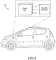
- FIG. 4 illustrates an automobile having a sensor system of the type shown in FIG. 3 , according to a non-limiting embodiment of the present application.
- MEMS microelectromechanical systems
- the two springs may be accordion springs, having a serpentine shape, extending along a direction of motion of the proof mass
- the coupler may be a bar extending along the direction of motion from one of the springs to the other.
- the bar may be rigid, thus restraining motion of the two springs relative to each other. In this manner, undesirable modes of vibration of the accordion springs may be inhibited during normal operating conditions of the MEMS device.
- the springs may include multiple folds. Multiple couplers may couple one spring to the other, for instance by coupling respective folds of one spring to the other.
- the couplers may all be rigid bars in some embodiments.
- the MEMS device is an energy harvesting device which harvests energy from the motion of the movable proof mass. It is desirable in at least some embodiments that the displacement of the proof mass from its equilibrium position is large, for example being greater than 200 microns. The larger the displacement, the greater the amount of energy which may be harvested.
- the couplers described herein as coupling together two accordion springs may facilitate the use of such springs in a MEMS device in which the proof mass is intended to undergo large displacements. The couplers may allow for large displacements in a preferred mode of vibration of the MEMS device, while inhibiting displacement associated with unwanted spurious modes of vibration.
- FIG. 1A is a perspective view of a MEMS device having a proof mass springedly connected to a substrate by accordion springs, with a bar coupling two of the accordion springs together, according to an embodiment of the present application.
- the MEMS device 100 includes a proof mass 102 , a substrate 104 with a cavity 105 , four accordion springs 106 a , 106 b , 106 c , and 106 d with respective anchor points 108 a , 108 b , 108 c , and 108 d , and two couplers 110 a and 110 b .
- FIG. 1B is a top-down view of the structure of FIG. 1A , with the substrate 104 omitted for ease of illustration.
- the proof mass 102 may have any suitable size and shape, and may be formed of any suitable material.
- the proof mass 102 may be rectangular (e.g., square), and may be formed of silicon.
- the proof mass 102 is formed of the same material as the substrate 104 .
- the substrate 104 may be a silicon substrate, and the proof mass 102 may be formed from the substrate 104 by suitable micromachining techniques (e.g., lithography and etching).
- the proof mass 102 may have a thickness T 1 between 0.3 mm and 3 mm, or any value or range of values within that range, as a non-limiting example.
- the proof mass 102 may have sides of length L 1 , between 3 mm and 20 mm, or any value or range of values within the range, as a non-limiting example.
- the substrate 104 may be a silicon substrate, or alternatively may be formed of other semiconductor materials, as a non-limiting example.
- the substrate 104 forms part of a wafer, such that multiple instances of the MEMS device 100 may be formed on the wafer simultaneously using wafer level fabrication techniques. In such embodiments, the individual MEMS devices may then be diced from the wafer.
- the cavity 105 may be formed in the substrate 104 using suitable micromachining techniques, such that the proof mass 102 is suspended above the cavity 105 . It should be appreciated that alternative embodiments do not include a cavity in the substrate, as there are alternative manners of achieving a movable proof mass relative to the substrate 104 .
- the accordion springs 106 a - 106 d which may alternatively be referred to herein as “accordion tethers,” “folded springs,” “folded tethers” or by other similar terminology, are substantially identical to each other in this non-limiting example, and each includes a single fold.
- an accordion spring may include more than one fold, with an example being illustrated in FIG. 2A and described further below.
- a pair of accordion springs is included on opposite sides of the proof mass 102 .
- a first pair comprising accordion springs 106 a and 106 b is on one side of the movable proof mass 102
- a second pair comprising accordion springs 106 c and 106 d is on the opposite side of the poof mass, such that the proof mass 102 is positioned between the pairs of accordion springs.
- the accordion springs 106 a - 106 d can expand and contract (or compress) along the y-axis ( FIG. 2 ), allowing movement of the proof mass 102 in that direction.
- the springs 106 a - 106 d are coupled to the substrate 104 at respective anchor points 108 a - 108 d , which are fixed.
- the anchor points may correspond to the ends of the respective accordion springs 106 a - 106 d .
- the anchor points may represent pillars extending down to a surface of the substrate.
- the ends of the accordion springs represented by the anchor points 108 a - 108 d may alternatively terminate on a side (or sidewall) of the substrate 104 in some embodiments.
- the accordion springs 106 a - 106 d may have any suitable dimensions.
- the accordion springs may have a thickness T 2 between 10 microns and 2 mm, or any value or range of values within that range, as a non-limiting example.
- they may have a length L 2 in the y-direction between 200 microns and 3 mm, or any value or range of values within that range, and the total meandering length will be longer.
- the length LS may determine the possible displacement of the proof mass, and thus may have a suitable value to provide a desired amount of displacement of the proof mass, for example being between 150 microns and 2 mm.
- the length LD of the segment providing the offset of the fold of the accordion springs from the proof mass may be approximately half the length LS.
- the widths W 1 of the accordion springs 106 a - 106 d , in the x-y plane, may vary along the length. For example, the width may be greater near the proof mass 102 and smaller near the anchor points. Alternative configurations are possible.
- the value of the widths W 1 may be selected to provide a desired resonance frequency of the MEMS device. In some embodiments, the widths W 1 may be between 1 microns and 300 microns, or any value or range of values within such ranges.
- the dimensions of the accordion springs may be selected to allow for large displacements of the proof mass in the y-direction.
- the lengths of the accordion springs and the positioning of the anchor points relative to the proof mass may be selected to allow for the accordion springs to expand and compress by between 0.3 mm and 5 mm, between 1 mm and 3 mm, or any value or range of values with such ranges.
- the range of motion of the proof mass 102 may be within those ranges, or larger distances in some embodiments.
- Such large displacements may be beneficial in various applications, such as when the MEMS device 100 is an energy harvester which harvests energy from the motion of the proof mass 102 .
- MEMS devices may include accordion springs with different shapes than 106 a - 106 d . That is, the shapes of accordion springs 106 a - 106 d are non-limiting examples. A further example is illustrated in FIG. 2F and described further below.
- the couplers 110 a and 110 b couple together accordion springs on opposite sides of the proof mass 102 .
- coupler 110 a couples together accordion springs 106 a and 106 c
- coupler 110 b couples together accordion springs 106 b and 106 d .
- the couplers 110 a and 110 b are substantially straight bars. They may have any suitable dimensions to provide a desired degree of rigidity. For example, they may have the same thickness T 2 as the accordion springs, but may have a width W 2 greater than the width W 1 .
- the width W 2 is between two and 20 times greater than W 1 , between two and 10 times greater than W 1 , or any value or range of values within those ranges.
- the width W 2 may be selected to be sufficient to substantially resist bending of the couplers 110 a and 110 b in the x or z directions, and to resist stretching or compressing in the y-direction under typical operating conditions of the MEMS device 100 .
- the width W 2 may be between 50 and 500 microns, or any value or range of values in that range.
- the width W 3 of the couplers 110 a and 110 b at the coupling points at which they couple to the accordion springs may be greater than the width W 2 .
- the width W 3 is between 1.5 and 5 times greater than W 2 , although alternatives are possible.
- the length L 3 of the couplers 110 a and 110 b is sufficient to extend around the proof mass 102 .
- the length L 3 may be between 1.25 and 3 times as long as the length L 1 of the proof mass 102 .
- the length L 4 may be sufficient provide a strong mechanical coupling between the spring and the coupler.
- L 4 is between 300 microns and 1.5 mm, although alternatives are possible.
- the inclusion of the couplers 110 a and 110 b does not significantly add to the size of the MEMS device 100 .
- the width of the couplers may be between 50 microns and 500 microns in some embodiments.
- the offset D 1 of the couplers from the proof mass 102 in the x-direction may be between 20 microns and 300 microns, or any value in that range.
- the presence of the couplers 110 a and 110 b may add less than 30% of the length L 1 to the device in the x-direction.
- less than 20%, or less than 10% of the length L 1 is added in the x-direction by including the couplers 110 a and 110 b .
- the benefits of the couplers may be achieved with a relatively small increase in device size.
- couplers are provided which couple outward facing surfaces of the accordion springs.
- couplers may be configured in alternative configurations to couple inward facing segments of the accordion springs. An example is shown in FIG. 2A and described further below.
- the couplers 110 a and 110 b may be formed of any suitable material, and in some embodiments are formed of the same materials as the accordion springs which they couple. For example, they may be formed from the same patterning and etching processes.
- FIGS. 1C, 1D, and 1E illustrate three different modes of operation of the MEMS device 100 of FIGS. 1A-1B . These figures omit the substrate 104 for simplicity of illustration.
- FIG. 1C illustrates the displacement of the MEMS device 100 associated with a fundamental mode of vibration of the mass spring system.
- the proof mass moves along the y-axis
- FIG. 1C illustrates a state in which the proof mass 102 is displaced from its equilibrium position in the negative y-direction.
- accordion springs 106 a and 106 b compress along the y-direction
- accordion springs 106 c and 106 d expand along the y-direction.
- the couplers 110 a and 110 b do not expand or contract, such that the distance between the coupled folds of the accordion springs remains the same.
- the distance between the coupling point of accordion spring 106 a and the coupling point of accordion spring 106 c remains unchanged from the equilibrium state of the MEMS device 100 .
- the distance between the coupling point of accordion spring 106 b and the coupling point of accordion spring 106 d remains unchanged from the equilibrium state.
- the motion illustrated in FIG. 1C represents the desired motion of the MEMS device 100 .
- the proof mass may undergo large displacements along the y-direction in response to experiencing vibration, acceleration, or some other condition of interest.
- the displacement generates an electrical signal which is detected by suitable electrodes and captured and stored by suitable circuitry.
- the motion of the proof mass may be converted to electrical energy that is harvested.
- the MEMS device 100 may be a sensor, such as an accelerometer or gyroscope, and the proof mass 102 may be displaced in response to a condition of interest, such as acceleration or rotation of the MEMS device 100 .
- the displacement may be detected, thus providing an indication of the experienced condition.
- the MEMS device may be an actuator.
- a system may include more than one such MEMS device configured as different types of devices selected from among harvesters, sensors, and actuators.
- FIG. 1D illustrates a mode of vibration in which the proof mass 102 is displaced along the z-axis.
- FIG. 1D illustrates a state in which the proof mass 102 is displaced from its equilibrium position in the positive z-direction.
- the couplers 110 a and 110 b may prevent the accordion springs 106 a - 106 d from freely twisting in response to such motion of the proof mass, and thus may inhibit the mode of vibration shown.
- FIG. 1E illustrates a mode of vibration in which the proof mass 102 rotates around the y-axis.
- FIG. 1E illustrates a state in which the proof mass 102 is rotated counterclockwise from its equilibrium position around the y-axis.
- the couplers 110 a and 110 b may prevent the accordion springs 106 a - 106 d from freely twisting in response to such motion of the proof mass, and thus may inhibit the mode of vibration shown.
- FIGS. 1D and 1E illustrate motion which may be undesirable in at least some embodiments, and thus the illustrated modes of vibration may be considered spurious modes.
- the proof mass 102 may be desirable for the proof mass 102 to exhibit the motion illustrated in FIG. 1C , along the y-axis. In such situations it may be beneficial to inhibit the occurrence of the motion shown in FIGS. 1D and 1E .
- the couplers 110 a and 110 b may result in the resonance frequencies of the modes of vibration shown in FIGS. 1D and 1E being sufficiently displaced in the frequency domain from the resonance frequency of the mode of vibration shown in FIG. 1C that they are unlikely to occur during typical operation of the MEMS device 100 .
- the couplers 110 a and 110 b may inhibit or entirely prevent the types of displacement shown in FIGS. 1D and 1E by providing a rigid connection between the accordion springs.
- the resonance frequencies associated with the modes of vibration illustrated in FIGS. 1D and 1E are significantly higher than the resonance frequency of the mode of vibration shown in FIG. 1C .
- the modes of vibration of FIGS. 1D and 1E may have resonance frequencies that are between 200 Hz and 3 kHz greater than the resonance frequency of the mode of vibration of FIG. 1C , or any value or range of values within that range.
- second and higher order modes of vibration of the mass-spring system may have resonance frequencies between 2 and 20 times greater than the resonance frequency of the first order mode of vibration.
- accordion springs coupling a proof mass to a substrate may include more than one fold.
- one or more couplers of the types described herein may couple together one or more folds of two accordion springs.
- FIGS. 2A and 2B illustrate a non-limiting example.
- MEMS device 200 includes many of the same components previously described in connection with FIGS. 1A and 1B , such that those components are not described in detail again here. It differs, however, in that multiple-fold accordion springs 206 a , 206 b , 206 c , and 206 d are provided to couple the proof mass 102 to the substrate 104 . Also, MEMS device 200 includes six couplers 210 a , 210 b , 210 c , 210 d , 210 e , and 210 f.
- each of the accordion springs 206 a - 206 d has three folds, in contrast to the single fold accordion springs of FIG. 1A .
- the couplers 210 a - 210 f couple together respective folds of opposing accordion springs. That is, couplers 210 a - 210 c couple together respective folds of the accordion springs 206 a and 206 c , while couplers 210 d - 210 f couple together respective folds of the accordion springs 206 b and 206 d .
- the couplers may have any suitable dimensions to provide a desired degree of rigidity. For example, the lengths, thicknesses, and widths of the couplers 210 a - 210 f may be within the ranges previously listed with respect to couplers 110 a and 110 b , or any other suitable dimensions.
- couplers 210 b , 210 c , 210 e , and 210 f may be substantially the same shape as each other, but 210 b and 210 e may be of different lengths than 210 c and 210 f to allow for coupling of different folds of the coupled accordion springs.
- Couplers 210 a and 210 d have a different shape than the other couplers because they couple surfaces of the accordion springs which are facing each other. Stated another way, the couplers 210 a and 210 d have wrap-around segments which wrap around the accordion springs.
- coupler 210 a includes wrap around segments 212 a and 212 b
- coupler 210 d includes wrap-around segments 212 c and 212 d
- couplers are provided which couple folds of accordion springs which face in different directions from each other.
- coupler 210 b couples to a fold of accordion spring 206 c made up of segments 211 c , 211 d , and 211 e which faces a different direction than the fold of accordion spring 206 c coupled by coupler 210 a made up of segments 211 a , 211 b , and 211 c.
- couplers are provided coupling each fold of opposing accordion springs.
- an alternative construction of the MEMS device shown in FIGS. 2A and 2B may have two couplers or four couplers, rather than six.
- couplers 210 b and 210 e may be omitted in an alternative embodiment.
- FIGS. 2C, 2D, and 2E illustrate three different modes of operation of the MEMS device of FIGS. 2A-2B .
- FIG. 2C illustrates a mode of vibration of the mass-spring system in which the proof mass moves in the y-direction.
- FIG. 2C illustrates a state in which the proof mass 102 is displaced from its equilibrium position in the negative y-direction.
- Accordion springs 206 a and 206 b compress and accordion springs 206 c and 206 d expand.
- the couplers 210 a - 210 f do not expand or compress and therefore the distances between respective folds of the coupled springs do not change.
- the mode of vibration represented in FIG. 2C represents a fundamental mode of vibration of the MEMS device 200 .
- FIG. 2D illustrates a mode of operation in which the proof mass 102 moves in the z-direction.
- FIG. 2D illustrates a state in which the proof mass 102 is displaced from its equilibrium position in the positive z-direction.
- the couplers 210 a - 210 f resist twisting of the accordion springs associated with such a mode of vibration, and thus inhibit the mode of vibration.
- FIG. 2E illustrates a mode of vibration in which the proof mass 102 rotates around the y-axis.
- FIG. 2E illustrates a state in which the proof mass rotates counterclockwise around the y-axis.
- the couplers 210 a - 210 f also resist this mode of operation.
- the couplers 210 a - 210 f may impact the resonance frequencies of certain modes of vibration.
- the resonance frequencies of the modes of vibration shown in FIGS. 2D and 2E may be substantially higher than the resonance frequency of the mode illustrated in FIG. 2C , making them less likely to occur during typical operation of the MEMS device 200 .
- the couplers 210 a - 210 f may inhibit or prevent entirely such modes of vibration.
- the resonance frequencies associated with the modes of vibration of FIGS. 2D and 2E may be between 200 Hz and 3 kHz higher than the resonance frequency associated with the mode of vibration of FIG. 2C .
- second and higher order modes of vibration of the mass-spring system may have resonance frequencies between 2 and 20 times greater than the resonance frequency of the first order mode of vibration. Thus, during typical operation of the MEMS device 200 such undesirable spurious modes of vibration may be suppressed.
- FIGS. 1A-1D and 2A-2E are non-limiting examples.
- Accordion springs may assume different shapes.
- FIG. 2F is a top down view of a MEMS device 220 .
- the MEMS device 220 includes a proof mass 222 , a first accordion spring formed by segments 224 a , 224 b , 224 c , and 224 d coupling the proof mass 222 to an anchor point 226 , and a second accordion spring formed by segments 228 a , 228 b , 228 c , and 228 d coupling the proof mass 222 to an anchor point 230 .
- Couplers 232 a and 232 b couple the accordion springs together.
- Still other shapes of accordion springs may be implemented in MEMS devices which include couplers coupling two or more accordion springs together.
- FIG. 3 is a system incorporating a MEMS inertial device of the types described herein.
- the system 300 is a sensor system including a MEMS sensor 302 , a power unit 304 , sense circuitry 306 , and an input/output (I/O) interface 308 .
- the MEMS sensor 302 may be a MEMS accelerometer, pressure sensor, gyroscope, or other type of sensor to sense a characteristic of interest.
- the power unit 304 may include an energy harvesting device 310 , for example the MEMS devices 100 or 200 previously described herein and operated as energy harvesting devices, and an energy storage device 312 .
- the energy storage device may be a battery, supercapacitor, or other suitable structure for storing energy harvested by the energy harvesting device 310 .
- the harvested energy may be used to power sense circuitry 306 which controls operation of the MEMS sensor 302 and/or processes signals output by the MEMS sensor 302 .
- the I/O interface 308 may be a wired or wireless interface for communicating with an external component, such as a computer, server, or other system.
- Systems incorporating MEMS devices of the types described herein may be implemented in various settings. As an example, such systems may be used in industrial settings. For example, industrial machinery may generate vibration which creates energy that can be harvested by the MEMS devices described herein. The harvested energy may be used to power a sensor monitoring performance of the industrial machinery and/or a processor controlling operation of the machinery.
- FIG. 4 illustrates an example, in which a car 400 includes sensor unit 401 and onboard computer 402 .
- the sensor unit 401 may be, for example, a system like that shown in FIG. 3 , including a MEMS sensor, a power unit with an energy harvester of the types described herein, sensor circuitry, and interface circuitry.
- the sensor unit 401 may comprise a package or housing attached to a suitable part of the automobile 400 .
- the sensor unit may, as an example, sense accelerations along the driving direction and/or perpendicular to the driving direction.
- the sensor unit 401 may be configured to sense vertical accelerations, thus monitoring, for example, the status of the suspension.
- the energy harvester of the sensor unit 401 may collect energy from motion of the car.
- Sensor unit 401 may communicate with onboard computer 402 , and may supply sense signals to the onboard computer.
- MEMS devices may be subjected to self-testing, in at least some embodiments.
- MEMS energy harvesters having coupled accordion springs of the types described herein may be self-tested by applying a suitable drive signal, and the resulting motion of the proof mass may be evaluated.
- Self-testing of other types of MEMS devices having coupled accordion springs, and not just energy harvesters, may also be performed.
- the terms “approximately” and “about” may be used to mean within ⁇ 20% of a target value in some embodiments, within ⁇ 10% of a target value in some embodiments, within ⁇ 5% of a target value in some embodiments, and yet within ⁇ 2% of a target value in some embodiments.
- the terms “approximately” and “about” may include the target value.
Landscapes
- Engineering & Computer Science (AREA)
- Chemical & Material Sciences (AREA)
- Combustion & Propulsion (AREA)
- Computer Hardware Design (AREA)
- Microelectronics & Electronic Packaging (AREA)
- Mechanical Engineering (AREA)
- General Engineering & Computer Science (AREA)
- Physics & Mathematics (AREA)
- General Physics & Mathematics (AREA)
- Micromachines (AREA)
Abstract
Description
Claims (20)
Priority Applications (3)
| Application Number | Priority Date | Filing Date | Title |
|---|---|---|---|
| US15/277,511 US10920756B2 (en) | 2016-09-27 | 2016-09-27 | Coupled accordion springs in microelectromechanical systems (MEMS) devices |
| CN202310644600.0A CN116605828A (en) | 2016-09-27 | 2017-09-27 | Coupling folded springs in microelectromechanical systems (MEMS) devices |
| CN201710885349.1A CN107867670A (en) | 2016-09-27 | 2017-09-27 | Folded spring is coupled in MEMS (MEMS) device |
Applications Claiming Priority (1)
| Application Number | Priority Date | Filing Date | Title |
|---|---|---|---|
| US15/277,511 US10920756B2 (en) | 2016-09-27 | 2016-09-27 | Coupled accordion springs in microelectromechanical systems (MEMS) devices |
Publications (2)
| Publication Number | Publication Date |
|---|---|
| US20180087491A1 US20180087491A1 (en) | 2018-03-29 |
| US10920756B2 true US10920756B2 (en) | 2021-02-16 |
Family
ID=61687724
Family Applications (1)
| Application Number | Title | Priority Date | Filing Date |
|---|---|---|---|
| US15/277,511 Active 2037-08-28 US10920756B2 (en) | 2016-09-27 | 2016-09-27 | Coupled accordion springs in microelectromechanical systems (MEMS) devices |
Country Status (2)
| Country | Link |
|---|---|
| US (1) | US10920756B2 (en) |
| CN (2) | CN107867670A (en) |
Families Citing this family (2)
| Publication number | Priority date | Publication date | Assignee | Title |
|---|---|---|---|---|
| CN109188021B (en) * | 2018-08-30 | 2020-06-16 | 太原理工大学 | Porous spring cantilever sensitive structure of low-frequency micro-acceleration sensor |
| US11099207B2 (en) | 2018-10-25 | 2021-08-24 | Analog Devices, Inc. | Low-noise multi-axis accelerometers and related methods |
Citations (16)
| Publication number | Priority date | Publication date | Assignee | Title |
|---|---|---|---|---|
| US6860151B2 (en) | 2003-02-07 | 2005-03-01 | Honeywell International Inc. | Methods and systems for controlling movement within MEMS structures |
| JP2006147995A (en) | 2004-11-24 | 2006-06-08 | Nippon Telegr & Teleph Corp <Ntt> | Variable capacitance element and manufacturing method thereof |
| CN101382564A (en) | 2007-09-07 | 2009-03-11 | 原相科技股份有限公司 | Micromachined sensors |
| US20090256297A1 (en) * | 2008-04-14 | 2009-10-15 | Freescale Semiconductor, Inc. | Spring member for use in a microelectromechanical systems sensor |
| US20100122577A1 (en) * | 2008-11-14 | 2010-05-20 | Reinhard Neul | Evaluation electronics system for a rotation-rate sensor |
| CN101844739A (en) | 2009-03-27 | 2010-09-29 | 深迪半导体(上海)有限公司 | Manufacturing method of subminiature MEMS gyroscope sensor |
| US20110062820A1 (en) * | 2009-09-15 | 2011-03-17 | Rohm Co., Ltd. | Power Generation Apparatus |
| CN201780110U (en) | 2009-07-21 | 2011-03-30 | 深迪半导体(上海)有限公司 | Mems gyroscope |
| US20120297876A1 (en) | 2011-05-26 | 2012-11-29 | Christoph Gauger | Micromechanical component having a damping device |
| US20140083210A1 (en) | 2012-09-25 | 2014-03-27 | Acreo Swedish Ict Ab | Device for measuring force components, and method for its production |
| US20140245832A1 (en) | 2013-03-01 | 2014-09-04 | Industrial Technology Research Institute | Micro-electro mechanical apparatus with interdigitated spring |
| US20150013455A1 (en) * | 2012-02-15 | 2015-01-15 | Commissariat A L'energie Atomique Et Aux Ene Alt | Compact device for detecting at least one acceleration and one speed of rotation |
| CN104955767A (en) | 2012-12-27 | 2015-09-30 | 特罗尼克斯微系统公司 | Micro-electromechanical device comprising a mobile mass that can move out-of-plane |
| US9246017B2 (en) | 2012-02-07 | 2016-01-26 | Mcube, Inc. | MEMS-based dual and single proof-mass accelerometer methods and apparatus |
| US20160131679A1 (en) | 2014-11-06 | 2016-05-12 | Richtek Technology Corporation | Mirco-electro-mechanical system (mems) device |
| US9372084B2 (en) * | 2012-04-04 | 2016-06-21 | Seiko Epson Corporation | Gyro sensor, electronic apparatus, and mobile unit |
-
2016
- 2016-09-27 US US15/277,511 patent/US10920756B2/en active Active
-
2017
- 2017-09-27 CN CN201710885349.1A patent/CN107867670A/en active Pending
- 2017-09-27 CN CN202310644600.0A patent/CN116605828A/en active Pending
Patent Citations (16)
| Publication number | Priority date | Publication date | Assignee | Title |
|---|---|---|---|---|
| US6860151B2 (en) | 2003-02-07 | 2005-03-01 | Honeywell International Inc. | Methods and systems for controlling movement within MEMS structures |
| JP2006147995A (en) | 2004-11-24 | 2006-06-08 | Nippon Telegr & Teleph Corp <Ntt> | Variable capacitance element and manufacturing method thereof |
| CN101382564A (en) | 2007-09-07 | 2009-03-11 | 原相科技股份有限公司 | Micromachined sensors |
| US20090256297A1 (en) * | 2008-04-14 | 2009-10-15 | Freescale Semiconductor, Inc. | Spring member for use in a microelectromechanical systems sensor |
| US20100122577A1 (en) * | 2008-11-14 | 2010-05-20 | Reinhard Neul | Evaluation electronics system for a rotation-rate sensor |
| CN101844739A (en) | 2009-03-27 | 2010-09-29 | 深迪半导体(上海)有限公司 | Manufacturing method of subminiature MEMS gyroscope sensor |
| CN201780110U (en) | 2009-07-21 | 2011-03-30 | 深迪半导体(上海)有限公司 | Mems gyroscope |
| US20110062820A1 (en) * | 2009-09-15 | 2011-03-17 | Rohm Co., Ltd. | Power Generation Apparatus |
| US20120297876A1 (en) | 2011-05-26 | 2012-11-29 | Christoph Gauger | Micromechanical component having a damping device |
| US9246017B2 (en) | 2012-02-07 | 2016-01-26 | Mcube, Inc. | MEMS-based dual and single proof-mass accelerometer methods and apparatus |
| US20150013455A1 (en) * | 2012-02-15 | 2015-01-15 | Commissariat A L'energie Atomique Et Aux Ene Alt | Compact device for detecting at least one acceleration and one speed of rotation |
| US9372084B2 (en) * | 2012-04-04 | 2016-06-21 | Seiko Epson Corporation | Gyro sensor, electronic apparatus, and mobile unit |
| US20140083210A1 (en) | 2012-09-25 | 2014-03-27 | Acreo Swedish Ict Ab | Device for measuring force components, and method for its production |
| CN104955767A (en) | 2012-12-27 | 2015-09-30 | 特罗尼克斯微系统公司 | Micro-electromechanical device comprising a mobile mass that can move out-of-plane |
| US20140245832A1 (en) | 2013-03-01 | 2014-09-04 | Industrial Technology Research Institute | Micro-electro mechanical apparatus with interdigitated spring |
| US20160131679A1 (en) | 2014-11-06 | 2016-05-12 | Richtek Technology Corporation | Mirco-electro-mechanical system (mems) device |
Non-Patent Citations (2)
| Title |
|---|
| Fedder, Simulation of Microelectromechanical Systems. Faculty of Electrical Engineering and Computer Sciences. University of California, Berkeley, CA. Dissertation. 1994. 319 pages. |
| Legtenberg et al., Comb-drive actuators for large displacements. J Micromech Microeng. 1996;6:320-9. |
Also Published As
| Publication number | Publication date |
|---|---|
| CN116605828A (en) | 2023-08-18 |
| CN107867670A (en) | 2018-04-03 |
| US20180087491A1 (en) | 2018-03-29 |
Similar Documents
| Publication | Publication Date | Title |
|---|---|---|
| US7513155B2 (en) | Inertial sensor | |
| CN211012984U (en) | MEMS device | |
| US7692366B2 (en) | Miniaturized piezoelectric based vibrational energy harvester | |
| US8413509B2 (en) | Spring member for use in a microelectromechanical systems sensor | |
| US9625489B2 (en) | Micromechanical sensor and method for manufacturing a micromechanical sensor | |
| US11733263B2 (en) | 3-axis accelerometer | |
| CN105103031A (en) | MEMS hinges with enhanced rotatability | |
| CN107003333B9 (en) | MEMS sensor and semiconductor package | |
| EP3564682B1 (en) | Inertial sensor with single proof mass and multiple sense axis capability | |
| JP6067026B2 (en) | Micro electro mechanical system (MEMS) | |
| JP2012515903A (en) | Yaw rate sensor | |
| JP5978140B2 (en) | Inertial sensor | |
| US10920756B2 (en) | Coupled accordion springs in microelectromechanical systems (MEMS) devices | |
| US7516661B2 (en) | Z offset MEMS device | |
| US9035400B2 (en) | Micro electro mechanical systems device | |
| US10520526B2 (en) | Folded tether structure for MEMS sensor devices | |
| JP5816320B2 (en) | MEMS element | |
| US9964561B2 (en) | Acceleration sensor | |
| US10598686B2 (en) | Micromechanical z-acceleration sensor | |
| EP4095484A1 (en) | Microelectromechanical device with out-of-plane stopper structure and process for manufacturing a microelectromechanical device | |
| JP6070112B2 (en) | Acceleration sensor | |
| JP6070111B2 (en) | Acceleration sensor | |
| JP2008203278A (en) | Method for manufacturing acceleration sensor |
Legal Events
| Date | Code | Title | Description |
|---|---|---|---|
| AS | Assignment |
Owner name: ANALOG DEVICES, INC., MASSACHUSETTS Free format text: ASSIGNMENT OF ASSIGNORS INTEREST;ASSIGNORS:ZHANG, QIAN;YANG, KUANG L.;GU, LEI;REEL/FRAME:039902/0925 Effective date: 20160926 |
|
| STPP | Information on status: patent application and granting procedure in general |
Free format text: RESPONSE TO NON-FINAL OFFICE ACTION ENTERED AND FORWARDED TO EXAMINER |
|
| STPP | Information on status: patent application and granting procedure in general |
Free format text: FINAL REJECTION MAILED |
|
| STPP | Information on status: patent application and granting procedure in general |
Free format text: DOCKETED NEW CASE - READY FOR EXAMINATION |
|
| STPP | Information on status: patent application and granting procedure in general |
Free format text: NON FINAL ACTION MAILED |
|
| STPP | Information on status: patent application and granting procedure in general |
Free format text: RESPONSE TO NON-FINAL OFFICE ACTION ENTERED AND FORWARDED TO EXAMINER |
|
| STPP | Information on status: patent application and granting procedure in general |
Free format text: FINAL REJECTION MAILED |
|
| STPP | Information on status: patent application and granting procedure in general |
Free format text: DOCKETED NEW CASE - READY FOR EXAMINATION |
|
| STPP | Information on status: patent application and granting procedure in general |
Free format text: NON FINAL ACTION MAILED |
|
| STCF | Information on status: patent grant |
Free format text: PATENTED CASE |