US10913167B2 - Sealing arrangement for use in robot joint - Google Patents
Sealing arrangement for use in robot joint Download PDFInfo
- Publication number
- US10913167B2 US10913167B2 US16/376,371 US201916376371A US10913167B2 US 10913167 B2 US10913167 B2 US 10913167B2 US 201916376371 A US201916376371 A US 201916376371A US 10913167 B2 US10913167 B2 US 10913167B2
- Authority
- US
- United States
- Prior art keywords
- side wall
- cavity
- sealing arrangement
- air
- sealing
- Prior art date
- Legal status (The legal status is an assumption and is not a legal conclusion. Google has not performed a legal analysis and makes no representation as to the accuracy of the status listed.)
- Active, expires
Links
Images


Classifications
-
- B—PERFORMING OPERATIONS; TRANSPORTING
- B25—HAND TOOLS; PORTABLE POWER-DRIVEN TOOLS; MANIPULATORS
- B25J—MANIPULATORS; CHAMBERS PROVIDED WITH MANIPULATION DEVICES
- B25J19/00—Accessories fitted to manipulators, e.g. for monitoring, for viewing; Safety devices combined with or specially adapted for use in connection with manipulators
- B25J19/0075—Means for protecting the manipulator from its environment or vice versa
- B25J19/0079—Means for protecting the manipulator from its environment or vice versa using an internal pressure system
-
- F—MECHANICAL ENGINEERING; LIGHTING; HEATING; WEAPONS; BLASTING
- F16—ENGINEERING ELEMENTS AND UNITS; GENERAL MEASURES FOR PRODUCING AND MAINTAINING EFFECTIVE FUNCTIONING OF MACHINES OR INSTALLATIONS; THERMAL INSULATION IN GENERAL
- F16J—PISTONS; CYLINDERS; SEALINGS
- F16J15/00—Sealings
- F16J15/16—Sealings between relatively-moving surfaces
- F16J15/40—Sealings between relatively-moving surfaces by means of fluid
- F16J15/406—Sealings between relatively-moving surfaces by means of fluid by at least one pump
-
- Y—GENERAL TAGGING OF NEW TECHNOLOGICAL DEVELOPMENTS; GENERAL TAGGING OF CROSS-SECTIONAL TECHNOLOGIES SPANNING OVER SEVERAL SECTIONS OF THE IPC; TECHNICAL SUBJECTS COVERED BY FORMER USPC CROSS-REFERENCE ART COLLECTIONS [XRACs] AND DIGESTS
- Y10—TECHNICAL SUBJECTS COVERED BY FORMER USPC
- Y10T—TECHNICAL SUBJECTS COVERED BY FORMER US CLASSIFICATION
- Y10T74/00—Machine element or mechanism
- Y10T74/20—Control lever and linkage systems
- Y10T74/20207—Multiple controlling elements for single controlled element
- Y10T74/20305—Robotic arm
- Y10T74/20329—Joint between elements
Definitions
- Embodiments of present disclosure generally relates to a mechanical apparatus, and more particularly, to a sealing arrangement for use in a robot joint.
- Robots especially industrial robots (also called robot arms) have been widely utilized to aid manufacturers, for example, improve productivity, product quality and worker safety in various application fields.
- Industrial robots have various axis configurations.
- the vast majority of articulated robots normally enable multiple degrees (for example, four to six degrees) of freedom depending on the designed number of axis.
- robots with more axes allow for greater flexibility and can perform a wider variety of applications than robots with fewer axes.
- Axis 1 of an industry robot is a robot joint between the robot base and the swing. This axis allows the robot to rotate and sweep over a wide range to cover the area on either side of the robot and even behind the robot. In some cases, this axis allows the robot to spin up to a full 180 degree range from the center point.
- a sealing arrangement for use in a robot joint comprises: a circular sealing assembly arranged between a swing and a base of the robot joint in a longitudinal direction, the circular sealing assembly defining a tubular cavity in a circumferential direction and having a gas inlet and a gas outlet; and an air channel coupled to the gas inlet and operable to conduct pressured air flow into the cavity to maintain an air pressure inside the cavity above an air pressure outside the cavity, and thereby a high-speed airflow out of the gas outlet.
- Such sealing arrangement can rely on its circular sealing assembly to effectively isolate the internal space of Axis 1 from especially the external solid contaminants. Further, with such continuously directed higher-pressure air flow into the cavity, a relative high-speed airflow out of the gas outlet can be achieved. In such a way, the liquid pollutions/contaminants can be stopped outside the cavity. In this way, a more reliable protection of the internal structure of Axis 1 can be achieved.
- the circular sealing assembling comprises: a sealing ring forming a first side wall and a top wall of the cavity, wherein the first side wall is oriented in the longitudinal direction and the top wall is fixed to the swing and oriented in a horizontal direction that is substantially perpendicular to the longitudinal direction.
- the circular sealing assembling further comprises: a base ring coaxially arranged with the sealing ring and forming a second side wall of the cavity, wherein the second side wall is oriented opposite to the first side wall.
- a base ring coaxially arranged with the sealing ring and forming a second side wall of the cavity, wherein the second side wall is oriented opposite to the first side wall.
- Such vertically oriented base ring (or the second side wall of the cavity), as the outmost barrier/blocking component, can effectively reduce the risk of the solid contaminants entering into the internal space of Axis 1 structure.
- the gas outlet is defined by the base ring together with the sealing ring, and thus the size of the gas outlet can be properly designed and tuned as needed.
- the circular sealing assembling further comprises: a radial seal arranged coaxially with the sealing ring and forming a bottom wall of the cavity, wherein the radial seal is positioned between a third side wall of the base and the first side wall in a radial direction.
- the radial seal is elastically arranged between the third side wall and the first side wall to abut against the third side wall and the first side wall in the radial direction.
- At least a portion of the radial seal is made of flexible material.
- the flexible material can help achieve a better sealing effect as it enables a sufficient contact with the counterpart surface.
- the flexible material is rubber
- the sealing arrangement further comprising: an air tube connected to the air channel via a tube connector, wherein the air tube is operable to conduct the pressured air that is supplied from an external air source.
- the air pressure inside the cavity is in a range of 35 KPa to 55 KPa.
- the air pressure inside the cavity is approximately 45 KPa.
- Such properly tuned air pressure inside the cavity is beneficial, because it not only provides a stable and sufficient pressure to against the contaminant's infiltration, but also avoids a too high pressure at which the radial seal may lose its sealing ability
- a robot joint In second aspect, a robot joint is provided.
- the robot joint comprises: a base; a swing coupled to the base; and the sealing arrangement according to the first aspect of present disclosure.
- sealing arrangement along with a continuously provided high air pressure inside the cavity of the sealing arrangement according to various embodiments of the present disclosure, the infiltration of solid and liquid pollutions or contaminants can be effectively avoided, and thereby a more reliable robot joint protection for Axis 1 can be achieved. Furthermore, such sealing arrangement according to various embodiments of the present disclosure has a simply structure/design, which enables a simple and straightforward manufacture/assembly process with a low cost.
- FIG. 1 is a perspective view of an industrial robot in an assembled state.
- FIG. 2 is a perspective view of an industrial robot of FIG. 1 applied in an upside down orientation in an assembled state.
- FIG. 3 shows an exploded perspective view of the sealing arrangement for use in a robot joint, according to embodiments of the present disclosure.
- FIG. 4 shows a detailed side view of the sealing arrangement for use in a robot joint, according to embodiments of the present disclosure.
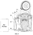
- FIG. 5 shows a cross-sectional view of the sealing arrangement for use in a robot joint according to embodiments of the present disclosure.
- FIG. 6 is a flowchart of manufacturing a sealing arrangement according to embodiments of the present disclosure.
- FIG. 7 shows an exploded view of the sealing arrangement for use in a robot joint in an unassembled state, according to embodiments of the present disclosure.
- FIG. 1 illustrates a general view of an industrial robot 1000 according to an embodiment of the present disclosure.
- Such industrial robot as shown in FIG. 1 may be used as a grinding/polishing machine to handle surface grinding and polishing process.
- such industrial robot may be used for grinding/polishing the case of a cellphone.
- the base 1 In a standard position as illustrated in FIG. 1 , the base 1 is fixed on the ground, and the swing 2 that is arranged on top of the base 1 could rotate around the Axis 1 which is defined as a robot joint between a base 1 and a swing 2 , so that the swing 2 could sweep within a large operation area.
- the industrial robot 1000 may also be adapted to be used in an upside down orientation as shown in FIG. 2 , depending on the specific requirements and operating conditions.
- the debris (such as metal debris) produced during the grinding process might be splashed around in an uncontrolled way and thereby increasing the risk of the infiltration of debris into the gap between the base 1 and the swing 2 .
- cooling water is normally introduced in order to cool down the heat produced during the grinding process.
- some blocking structures for example, the wall of a base ring
- the slurry-like mixture produced from the cooling water and the debris may still be able to flow into the internal structure of Axis 1 due to the liquid surface tension.
- Liquid surface tension helps the liquid climb over the wall to arrive at the internal space of the Axis 1 structures, such as sealing structure, drive train structure, electrical parts and cables, which will damage the internal Axis 1 structure and thereby deteriorate the overall performance of the robot.
- FIG. 3 shows a detailed side view of the sealing arrangement 100 for use in a robot joint 200 as illustrated in FIG. 1 .
- the sealing arrangement 100 generally includes a circular sealing assembly 110 (with its cross section being labeled by a dashed box) and an air channel 1 a coupled to the sealing assembly 110 .
- the circular sealing assembly 110 is arranged between the swing 2 and the base 1 of the robot joint 200 in a longitudinal direction Y.
- the circular sealing assembly 110 is arranged surrounding the Axis 1 structure for sealing the gap existing between the swing 2 and the base 1 of the robot joint 200 .
- the sealing arrangement 100 as shown in FIG. 3 can rely on its walls to effectively isolate the internal space of Axis 1 from the external solid contaminants.
- the circular sealing assembly 110 defines a tubular cavity 120 in a circumferential direction C and has a gas inlet 111 and a gas outlet 112 connected with the cavity 120 .
- the air channel 1 a is coupled to the gas inlet 111 and operable to continuously conduct pressured air flow into the cavity 120 to maintain an air pressure inside the cavity 120 above an air pressure outside the cavity 120 , and thereby a high-speed airflow coming out of the gas outlet.
- the higher air pressure inside the cavity 120 along with the high-speed air flow coming out of the gas outlet 112 helps further improve the sealing effect, because the pressured air coming out of the cavity 120 through the gas outlet 112 can further stop the liquid contaminant, such as slurry-like mixture, infiltrating into the cavity and the internal space of Axis 1 structure.
- the gas outlet 112 has a relative small feature size, for example, approximately 1 mm. Such small feature size, on one hand, is beneficial to keep a relatively strong air flow coming out of the gas outlet 112 , and on the other hand, will prevent the contaminants from infiltrating into the internal space of the cavity 120 and thus into the internal space of the robot joint 200 . It is to be understood that although FIG. 3 shows a vertically oriented gas outlet 112 , the scope of the present disclosure is not limited to the shape or the orientation of the gas outlet 112 . Those skilled in the art would have a motivation to modify the shape or the orientation of gas outlet 112 according to the requirements.
- FIG. 4 shows an exploded perspective view of the sealing arrangement 100 for use in a robot joint 200 .
- the circular sealing assembling 110 includes a sealing ring 9 .
- the sealing ring 9 forms a first side wall 901 and a top wall 902 of the cavity 120 .
- the sealing ring 9 has a substantially inverted “L” shaped cross section.
- the first side wall 901 is oriented in the longitudinal direction Y and the top wall 902 is to be fixed to the swing 2 and oriented in a horizontal direction X that is substantially perpendicular to the longitudinal direction Y.
- the sealing ring 9 is fixed to the swing 2 via fixing means.
- the sealing ring 9 can be fixed to the swing 2 via at least one screw 11 .
- an intermediate part, such as gasket 10 is arranged between an end surface of the swing 2 and the sealing ring 9 in order to provide additional sealing between the two components.
- the scope of the present disclosure is not limited by the type of fixing/connecting mechanism between the sealing ring 9 and the swing 2 . Any suitable fixing/connecting mechanisms, such as a clip assembly, a magnet assembly, and an adhesive assembly that can achieve same or similar sealing effect are possible as well.
- the circular sealing assembling 110 may further include a base ring 8 .
- the base ring 8 is coaxially arranged with the sealing ring 9 and forms a second side wall 801 of the cavity 120 .
- the second side wall 801 is oriented opposite to the first side wall 901 .
- the second side wall 801 is also substantially oriented in the longitudinal Y direction.
- the second side wall 801 is fixed at the top opening of the base 1 via interference fit.
- Such vertically oriented base ring 8 (or the second side wall 801 of the cavity 120 ) as shown in FIG. 3 or 4 functions as the outmost barrier/blocking component which can effectively stop the solid contaminants to enter the internal space of Axis 1 structure.
- the circular sealing assembling 110 further includes a radial seal 7 .
- the radial seal 7 is also arranged coaxially with the sealing ring 9 and forming a bottom wall 701 of the cavity 120 .
- the radial seal 7 may be positioned between a third side wall 101 of the base 1 and the first side wall 901 in a radial direction R.
- the gas inlet 111 is defined by the radial seal 7 and the base ring 8
- the gas outlet 112 is defined by the sealing ring 9 and the base ring 8 . In this way, the size of gas inlet 111 and gas outlet 112 can both be properly designed and tuned.
- the radial seal 7 is elastically arranged between the third side wall 101 and the first side wall 901 to abut against the third side wall 101 and the first side wall 901 in the radial direction R.
- the radial seal 7 may have an inverted “V” shaped cross section (or the so-called V-shaped sealing ring), and at least a portion of the radial seal 7 is made of flexible material such as rubber.
- the V-shaped sealing ring 7 can help achieve a better sealing effect as it enables a sufficient contact with the counterpart surface and the compressed amount is tunable via the angle of the V-shaped cross section.
- the sealing arrangement 100 may further include an air tube 5 which is connected to the air channel 1 a via a tube connector 6 .
- the air tube 5 is operable to conduct the pressured air that is supplied from an external air source as shown in FIG. 5 into the cavity 20 .
- One end of the tube connector 6 is shaped to fit with the channel 1 a and the other end of the tube connector 6 is shaped to receive the tube 5 , so that the connector 6 can be detachably connected with both the channel 1 a and the tube 5 .
- the channel 1 a is built as part of the top wall of the base 1 , which may improve the integrity of the whole sealing arrangement 100 and meanwhile saves the internal space for accommodating the channel 1 a . It is to be understood that the example described with reference to FIG. 3 is only for illustration, without suggesting any limitations as to the scope of the present disclosure.
- the channel 1 a with any other suitable shape, dimension, or orientation can be utilized in the sealing arrangement 100 .
- the air pressure inside the cavity 120 can be in a relatively broad range of 35 KPa to 55 KPa. However, in an ideal case, the air pressure inside the cavity 120 is properly tuned to approximately 45 KPa. Such properly tuned air pressure inside the cavity 120 is beneficial, because it not only provides a stable and sufficient pressure to against the contaminant's infiltration, but also avoids a too high pressure at which the radial seal 7 may lose its sealing ability.
- FIG. 6 is a flowchart of a method 600 for manufacturing a sealing arrangement 100 according to embodiments of the present disclosure.
- FIG. 7 shows an exploded view of the sealing arrangement for use in a robot joint in an unassembled state, according to embodiments of the present disclosure.
- the sealing arrangement 100 as described above can be manufactured in a simple and straightforward way. Actions of the method 600 will now be described with reference to FIGS. 6 and 7 .
- the circular sealing assembly 110 defining a tubular cavity 120 in a circumferential direction C and having a gas inlet 111 and a gas outlet 112 is arranged between the swing 2 and the base 1 of the robot joint 200 in a longitudinal direction Y.
- arranging the circular sealing assembly 110 may include arranging the base ring 8 via interference fit to an upper opening of the base 1 to define a second side wall 801 of the cavity 120 ; arranging the radial seal 7 coaxially with the base ring 8 to define the bottom wall 701 of the cavity 120 ; and arranging the sealing ring 9 pre-fixed to the swing 2 to define the first side wall 901 and the top wall 902 of the cavity 120 , respectively.
- an air channel 1 a is coupled to the gas inlet 111 to conduct high pressured air into the cavity 120 .
- coupling the air channel to the gas inlet to conduct pressured air includes: connecting one end of an air tube 5 to the air channel 1 a via a tube connector 6 ; connecting the other end of the air tube 5 to an external air source; and supplying the pressured air from the external air source to the cavity 120 .
- method 600 may further includes fixing a base cover 3 with some screws 4 in order isolate the external air source from the air tube 5 and therefore the internal space of the base 1 .
- the ideal inside pressure is set to be 45 KPa.
- the air pressure that actually needs to be pumped into the gas inlet 111 is in a range of 50 KPa to 55 KPa considering the air leakage from gas outlet 112 .
- the upper limit of 55 KPa indicates an air pressure level beyond which the radial seal 7 may lose its sealing ability
- the lower level of 50 KPa indicates an air pressure at which the sealing arrangement 100 may not be able to provide stable and sufficient air flow to against the contaminant infiltration.
Abstract
A sealing arrangement for application in a robot joint. The sealing arrangement includes: a circular sealing assembly arranged between a swing and a base of the robot joint in a longitudinal direction, the circular sealing assembly defining a tubular cavity in a circumferential direction and having a gas inlet and a gas outlet; and an air channel coupled to the gas inlet and operable to continuously conduct pressured air flow into the cavity to maintain an air pressure inside the cavity above an air pressure outside the cavity, and thereby a high-speed airflow out of the gas outlet.
Description
Embodiments of present disclosure generally relates to a mechanical apparatus, and more particularly, to a sealing arrangement for use in a robot joint.
Robots, especially industrial robots (also called robot arms) have been widely utilized to aid manufacturers, for example, improve productivity, product quality and worker safety in various application fields. Industrial robots have various axis configurations. The vast majority of articulated robots normally enable multiple degrees (for example, four to six degrees) of freedom depending on the designed number of axis. In general, robots with more axes allow for greater flexibility and can perform a wider variety of applications than robots with fewer axes.
Axis 1 of an industry robot is a robot joint between the robot base and the swing. This axis allows the robot to rotate and sweep over a wide range to cover the area on either side of the robot and even behind the robot. In some cases, this axis allows the robot to spin up to a full 180 degree range from the center point.
However, for most of the current industrial robots, there is usually a gap existing in a region of Axis 1 between the base and the swing. In this case, pollutions/contaminants from the ambient, and otherwise, debris generated during the operation of the industry robot might cause issues and directly impact the performance of industrial robots. For example, the produced metal debris will be splashed around, or some liquid pollution might flow into the internal space of Axis 1 when the robot is operating in humid ambient. Once the infiltration of contaminants occurs, the internal structure of Axis 1 might be damaged, which will inevitably deteriorate the performance of the Axis 1 and thus the overall performance of the robot.
In first aspect, a sealing arrangement for use in a robot joint is provided. The sealing arrangement comprises: a circular sealing assembly arranged between a swing and a base of the robot joint in a longitudinal direction, the circular sealing assembly defining a tubular cavity in a circumferential direction and having a gas inlet and a gas outlet; and an air channel coupled to the gas inlet and operable to conduct pressured air flow into the cavity to maintain an air pressure inside the cavity above an air pressure outside the cavity, and thereby a high-speed airflow out of the gas outlet.
Such sealing arrangement can rely on its circular sealing assembly to effectively isolate the internal space of Axis 1 from especially the external solid contaminants. Further, with such continuously directed higher-pressure air flow into the cavity, a relative high-speed airflow out of the gas outlet can be achieved. In such a way, the liquid pollutions/contaminants can be stopped outside the cavity. In this way, a more reliable protection of the internal structure of Axis 1 can be achieved.
In some embodiments, the circular sealing assembling comprises: a sealing ring forming a first side wall and a top wall of the cavity, wherein the first side wall is oriented in the longitudinal direction and the top wall is fixed to the swing and oriented in a horizontal direction that is substantially perpendicular to the longitudinal direction.
In some embodiments, the circular sealing assembling further comprises: a base ring coaxially arranged with the sealing ring and forming a second side wall of the cavity, wherein the second side wall is oriented opposite to the first side wall. Such vertically oriented base ring (or the second side wall of the cavity), as the outmost barrier/blocking component, can effectively reduce the risk of the solid contaminants entering into the internal space of Axis 1 structure. In some embodiments, the gas outlet is defined by the base ring together with the sealing ring, and thus the size of the gas outlet can be properly designed and tuned as needed.
In some embodiments, the circular sealing assembling further comprises: a radial seal arranged coaxially with the sealing ring and forming a bottom wall of the cavity, wherein the radial seal is positioned between a third side wall of the base and the first side wall in a radial direction.
In some embodiments, the radial seal is elastically arranged between the third side wall and the first side wall to abut against the third side wall and the first side wall in the radial direction.
In some embodiments, at least a portion of the radial seal is made of flexible material. The flexible material can help achieve a better sealing effect as it enables a sufficient contact with the counterpart surface.
In some embodiments, the flexible material is rubber.
In some embodiments, the sealing arrangement further comprising: an air tube connected to the air channel via a tube connector, wherein the air tube is operable to conduct the pressured air that is supplied from an external air source.
In some embodiments, the air pressure inside the cavity is in a range of 35 KPa to 55 KPa.
In some embodiments, the air pressure inside the cavity is approximately 45 KPa. Such properly tuned air pressure inside the cavity is beneficial, because it not only provides a stable and sufficient pressure to against the contaminant's infiltration, but also avoids a too high pressure at which the radial seal may lose its sealing ability
In second aspect, a robot joint is provided. The robot joint comprises: a base; a swing coupled to the base; and the sealing arrangement according to the first aspect of present disclosure.
It would be apparent through the following discussions that by using such sealing arrangement along with a continuously provided high air pressure inside the cavity of the sealing arrangement according to various embodiments of the present disclosure, the infiltration of solid and liquid pollutions or contaminants can be effectively avoided, and thereby a more reliable robot joint protection for Axis 1 can be achieved. Furthermore, such sealing arrangement according to various embodiments of the present disclosure has a simply structure/design, which enables a simple and straightforward manufacture/assembly process with a low cost.
Drawings described herein are provided to further explain the present disclosure and constitute a part of the present application. The example embodiments of the disclosure and the explanation thereof are used to explain the present disclosure, rather than to limit the present disclosure improperly.
Throughout the drawings, the same or similar reference symbols are used to indicate the same or similar elements.
Principles of the present disclosure will now be described with reference to several example embodiments shown in the drawings. Though example embodiments of the present disclosure are illustrated in the drawings, it is to be understood that the embodiments are described only to facilitate those skilled in the art in better understanding and thereby achieving the present disclosure, rather than to limit the scope of the disclosure in any manner.
As discussed above, the debris (such as metal debris) produced during the grinding process might be splashed around in an uncontrolled way and thereby increasing the risk of the infiltration of debris into the gap between the base 1 and the swing 2. In particular, when the robot is used in humid environments, such as wet grinding environment, cooling water is normally introduced in order to cool down the heat produced during the grinding process. In this case, even some blocking structures (for example, the wall of a base ring) may be designed and arranged to block the splashed solid debris, the slurry-like mixture produced from the cooling water and the debris may still be able to flow into the internal structure of Axis 1 due to the liquid surface tension. Liquid surface tension helps the liquid climb over the wall to arrive at the internal space of the Axis 1 structures, such as sealing structure, drive train structure, electrical parts and cables, which will damage the internal Axis 1 structure and thereby deteriorate the overall performance of the robot.
Still in reference to FIG. 3 , the circular sealing assembly 110 defines a tubular cavity 120 in a circumferential direction C and has a gas inlet 111 and a gas outlet 112 connected with the cavity 120. The air channel 1 a is coupled to the gas inlet 111 and operable to continuously conduct pressured air flow into the cavity 120 to maintain an air pressure inside the cavity 120 above an air pressure outside the cavity 120, and thereby a high-speed airflow coming out of the gas outlet. The higher air pressure inside the cavity 120 along with the high-speed air flow coming out of the gas outlet 112 helps further improve the sealing effect, because the pressured air coming out of the cavity 120 through the gas outlet 112 can further stop the liquid contaminant, such as slurry-like mixture, infiltrating into the cavity and the internal space of Axis 1 structure.
In some embodiments, the gas outlet 112 has a relative small feature size, for example, approximately 1 mm. Such small feature size, on one hand, is beneficial to keep a relatively strong air flow coming out of the gas outlet 112, and on the other hand, will prevent the contaminants from infiltrating into the internal space of the cavity 120 and thus into the internal space of the robot joint 200. It is to be understood that although FIG. 3 shows a vertically oriented gas outlet 112, the scope of the present disclosure is not limited to the shape or the orientation of the gas outlet 112. Those skilled in the art would have a motivation to modify the shape or the orientation of gas outlet 112 according to the requirements.
In some embodiments, the sealing ring 9 is fixed to the swing 2 via fixing means. For example, as shown in FIG. 4 , the sealing ring 9 can be fixed to the swing 2 via at least one screw 11. In some embodiments, an intermediate part, such as gasket 10, is arranged between an end surface of the swing 2 and the sealing ring 9 in order to provide additional sealing between the two components. The scope of the present disclosure is not limited by the type of fixing/connecting mechanism between the sealing ring 9 and the swing 2. Any suitable fixing/connecting mechanisms, such as a clip assembly, a magnet assembly, and an adhesive assembly that can achieve same or similar sealing effect are possible as well.
In some embodiments, the circular sealing assembling 110 may further include a base ring 8. The base ring 8 is coaxially arranged with the sealing ring 9 and forms a second side wall 801 of the cavity 120. The second side wall 801 is oriented opposite to the first side wall 901. In other words, the second side wall 801 is also substantially oriented in the longitudinal Y direction. In some embodiments, the second side wall 801 is fixed at the top opening of the base 1 via interference fit. Of course, other securing mechanisms of the base ring 8 onto the top opening of the base 1 are also possible. Such vertically oriented base ring 8 (or the second side wall 801 of the cavity 120) as shown in FIG. 3 or 4 functions as the outmost barrier/blocking component which can effectively stop the solid contaminants to enter the internal space of Axis 1 structure.
Alternatively, or in addition, in some embodiments, the circular sealing assembling 110 further includes a radial seal 7. The radial seal 7 is also arranged coaxially with the sealing ring 9 and forming a bottom wall 701 of the cavity 120. As shown in FIG. 4 , the radial seal 7 may be positioned between a third side wall 101 of the base 1 and the first side wall 901 in a radial direction R. In such embodiment, the gas inlet 111 is defined by the radial seal 7 and the base ring 8, and the gas outlet 112 is defined by the sealing ring 9 and the base ring 8. In this way, the size of gas inlet 111 and gas outlet 112 can both be properly designed and tuned.
In some embodiments, the radial seal 7 is elastically arranged between the third side wall 101 and the first side wall 901 to abut against the third side wall 101 and the first side wall 901 in the radial direction R. For example, the radial seal 7 may have an inverted “V” shaped cross section (or the so-called V-shaped sealing ring), and at least a portion of the radial seal 7 is made of flexible material such as rubber. The V-shaped sealing ring 7 can help achieve a better sealing effect as it enables a sufficient contact with the counterpart surface and the compressed amount is tunable via the angle of the V-shaped cross section.
The sealing arrangement 100 may further include an air tube 5 which is connected to the air channel 1 a via a tube connector 6. The air tube 5 is operable to conduct the pressured air that is supplied from an external air source as shown in FIG. 5 into the cavity 20. One end of the tube connector 6 is shaped to fit with the channel 1 a and the other end of the tube connector 6 is shaped to receive the tube 5, so that the connector 6 can be detachably connected with both the channel 1 a and the tube 5.
Returning to FIG. 3 , in some embodiments, the channel 1 a is built as part of the top wall of the base 1, which may improve the integrity of the whole sealing arrangement 100 and meanwhile saves the internal space for accommodating the channel 1 a. It is to be understood that the example described with reference to FIG. 3 is only for illustration, without suggesting any limitations as to the scope of the present disclosure. The channel 1 a with any other suitable shape, dimension, or orientation can be utilized in the sealing arrangement 100.
In some embodiments, the air pressure inside the cavity 120 can be in a relatively broad range of 35 KPa to 55 KPa. However, in an ideal case, the air pressure inside the cavity 120 is properly tuned to approximately 45 KPa. Such properly tuned air pressure inside the cavity 120 is beneficial, because it not only provides a stable and sufficient pressure to against the contaminant's infiltration, but also avoids a too high pressure at which the radial seal 7 may lose its sealing ability.
In accordance with embodiments of the present disclosure, the sealing arrangement 100 as described above can be manufactured in a simple and straightforward way. Actions of the method 600 will now be described with reference to FIGS. 6 and 7 .
At block 602, the circular sealing assembly 110 defining a tubular cavity 120 in a circumferential direction C and having a gas inlet 111 and a gas outlet 112 is arranged between the swing 2 and the base 1 of the robot joint 200 in a longitudinal direction Y. In some embodiments, arranging the circular sealing assembly 110 may include arranging the base ring 8 via interference fit to an upper opening of the base 1 to define a second side wall 801 of the cavity 120; arranging the radial seal 7 coaxially with the base ring 8 to define the bottom wall 701 of the cavity 120; and arranging the sealing ring 9 pre-fixed to the swing 2 to define the first side wall 901 and the top wall 902 of the cavity 120, respectively.
At block 604, an air channel 1 a is coupled to the gas inlet 111 to conduct high pressured air into the cavity 120. In some embodiments, coupling the air channel to the gas inlet to conduct pressured air includes: connecting one end of an air tube 5 to the air channel 1 a via a tube connector 6; connecting the other end of the air tube 5 to an external air source; and supplying the pressured air from the external air source to the cavity 120. Optionally, method 600 may further includes fixing a base cover 3 with some screws 4 in order isolate the external air source from the air tube 5 and therefore the internal space of the base 1.
In an example, the ideal inside pressure is set to be 45 KPa. In order to achieve such an ideal inside pressure, the air pressure that actually needs to be pumped into the gas inlet 111 is in a range of 50 KPa to 55 KPa considering the air leakage from gas outlet 112. In this example, the upper limit of 55 KPa indicates an air pressure level beyond which the radial seal 7 may lose its sealing ability, and the lower level of 50 KPa indicates an air pressure at which the sealing arrangement 100 may not be able to provide stable and sufficient air flow to against the contaminant infiltration.
It should be appreciated that the above detailed embodiments of the present disclosure are only to exemplify or explain principles of the present disclosure and not to limit the present disclosure. Therefore, any modifications, equivalent alternatives and improvement, etc. without departing from the spirit and scope of the present disclosure shall be included in the scope of protection of the present disclosure. Meanwhile, appended claims of the present disclosure aim to cover all the variations and modifications falling under the scope and boundary of the claims or equivalents of the scope and boundary.
Claims (20)
1. A sealing arrangement for use in a robot joint, comprising:
a circular sealing assembly arranged between a swing and a base of the robot joint in a longitudinal direction, the circular sealing assembly defining a tubular cavity in a circumferential direction and having a gas inlet and a gas outlet, and comprising a sealing ring forming a first side wall and a top wall of the cavity, wherein the first side wall is oriented in the longitudinal direction and the top wall is fixed to the swing and oriented in a horizontal direction that is substantially perpendicular to the longitudinal direction; and
an air channel coupled to the gas inlet and operable to conduct pressured air into the cavity to maintain an air pressure inside the cavity above an air pressure outside the cavity.
2. The sealing arrangement according to claim 1 , wherein the circular sealing assembly comprises:
a base ring coaxially arranged with the sealing ring and forming a second side wall of the cavity, wherein the second side wall is oriented opposite to the first side wall.
3. The sealing arrangement according to claim 1 , wherein the circular sealing assembly further comprises:
a radial seal arranged coaxially with the sealing ring and forming a bottom wall of the cavity, wherein the radial seal is positioned between a third side wall of the base and the first side wall in a radial direction.
4. The sealing arrangement of claim 3 , wherein the radial seal is elastic and is arranged between the third side wall and the first side wall to abut against the third side wall and the first side wall in the radial direction.
5. The sealing arrangement of claim 4 , wherein at least a portion of the radial seal is made of flexible material.
6. The sealing arrangement of claim 5 , wherein the flexible material is rubber.
7. The sealing arrangement according to claim 1 , further comprising:
an air tube connected to the air channel via a tube connector, wherein the air tube is operable to conduct the pressured air that is supplied from an external air source.
8. The sealing arrangement according to claim 1 , wherein the air pressure inside the cavity is in a range of 35 KPa to 55 KPa.
9. The sealing arrangement of claim 8 , wherein the air pressure inside the cavity is approximately 45 KPa.
10. The sealing arrangement according to claim 2 , wherein the circular sealing assembly further comprises:
a radial seal arranged coaxially with the sealing ring and forming a bottom wall of the cavity, wherein the radial seal is positioned between a third side wall of the base and the first side wall in a radial direction.
11. The sealing arrangement of claim 10 , wherein the radial seal is elastic and is arranged between the third side wall and the first side wall to abut against the third side wall and the first side wall in the radial direction.
12. The sealing arrangement according to claim 2 , further comprising:
an air tube connected to the air channel via a tube connector, wherein the air tube is operable to conduct the pressured air that is supplied from an external air source.
13. The sealing arrangement of claim 11 , wherein at least a portion of the radial seal is made of flexible material.
14. The sealing arrangement of claim 13 , wherein the flexible material is rubber.
15. The sealing arrangement of claim 14 , further comprising:
an air tube connected to the air channel via a tube connector, wherein the air tube is operable to conduct the pressured air that is supplied from an external air source.
16. The sealing arrangement of claim 15 , wherein the air pressure inside the cavity is in a range of 35 KPa to 55 KPa.
17. The sealing arrangement of claim 16 , wherein the air pressure inside the cavity is approximately 45 KPa.
18. The sealing arrangement of claim 12 , wherein a radial seal is elastic and is arranged between a third side wall and the first side wall to abut against the third side wall and the first side wall in a radial direction.
19. The sealing arrangement of claim 18 , wherein at least a portion of the radial seal is made of flexible material.
20. A robot joint, comprising:
a base;
a swing coupled to the base; and
a sealing arrangement including:
a circular sealing assembly arranged between a swing and a base of the robot joint in a longitudinal direction, the circular sealing assembly defining a tubular cavity in a circumferential direction and having a gas inlet and a gas outlet, and comprising a sealing ring forming a first side wall and a top wall of the cavity, wherein the first side wall is oriented in the longitudinal direction and the top wall is fixed to the swing and oriented in a horizontal direction that is substantially perpendicular to the longitudinal direction; and
an air channel coupled to the gas inlet and operable to conduct pressured air into the cavity to maintain an air pressure inside the cavity above an air pressure outside the cavity.
Applications Claiming Priority (1)
| Application Number | Priority Date | Filing Date | Title |
|---|---|---|---|
| PCT/CN2016/108582 WO2018102965A1 (en) | 2016-12-05 | 2016-12-05 | Sealing arrangement for use in robot joint |
Related Parent Applications (1)
| Application Number | Title | Priority Date | Filing Date |
|---|---|---|---|
| PCT/CN2016/108582 Continuation WO2018102965A1 (en) | 2016-12-05 | 2016-12-05 | Sealing arrangement for use in robot joint |
Publications (2)
| Publication Number | Publication Date |
|---|---|
| US20190232506A1 US20190232506A1 (en) | 2019-08-01 |
| US10913167B2 true US10913167B2 (en) | 2021-02-09 |
Family
ID=62491710
Family Applications (1)
| Application Number | Title | Priority Date | Filing Date |
|---|---|---|---|
| US16/376,371 Active 2037-04-21 US10913167B2 (en) | 2016-12-05 | 2019-04-05 | Sealing arrangement for use in robot joint |
Country Status (4)
| Country | Link |
|---|---|
| US (1) | US10913167B2 (en) |
| EP (1) | EP3548230B1 (en) |
| CN (1) | CN109789566B (en) |
| WO (1) | WO2018102965A1 (en) |
Families Citing this family (9)
| Publication number | Priority date | Publication date | Assignee | Title |
|---|---|---|---|---|
| CN112074677B (en) * | 2018-05-03 | 2023-01-31 | Abb瑞士股份有限公司 | Robot |
| CN108943025A (en) * | 2018-08-30 | 2018-12-07 | 合肥固泰自动化有限公司 | A kind of heavy-load robot rotating base that 360 ° omni-directional is dust-proof |
| CN109986602A (en) * | 2019-03-28 | 2019-07-09 | 上海发那科机器人有限公司 | A kind of robot water-tight device |
| IT202000008974A1 (en) * | 2020-04-24 | 2021-10-24 | Romaco Srl | EQUIPMENT FOR FILLING CONTAINERS WITH A POWDER MATERIAL |
| CN115003937A (en) * | 2020-05-03 | 2022-09-02 | Abb瑞士股份有限公司 | Sealing assembly and robot |
| WO2022051989A1 (en) * | 2020-09-10 | 2022-03-17 | Abb Schweiz Ag | Sealing structure for robot joint and robot joint including such sealing structure |
| WO2022061589A1 (en) * | 2020-09-23 | 2022-03-31 | Abb Schweiz Ag | Robot arm assembly and robot |
| CN112510735B (en) * | 2020-09-24 | 2023-06-20 | 葛炽昌 | Power dispatching system and power dispatching method |
| USD979623S1 (en) * | 2020-10-20 | 2023-02-28 | Abb Schweiz Ag | Industrial robot |
Citations (17)
| Publication number | Priority date | Publication date | Assignee | Title |
|---|---|---|---|---|
| US3735990A (en) * | 1970-06-26 | 1973-05-29 | Bosch Gmbh Robert | Sealing structure for rotary motion transmitting device |
| US4698568A (en) * | 1985-03-29 | 1987-10-06 | Mitsubishi Jukogyo Kabushiki Kaisha | Antiexplosion structure in a working robot |
| US4716785A (en) * | 1985-08-20 | 1988-01-05 | Tokico Ltd. | Playback industrial robot provided with a driving device having an electric motor |
| US4732526A (en) * | 1884-06-29 | 1988-03-22 | Fanuc Ltd. | Explosion-proof industrial robot |
| JPH01222887A (en) | 1988-03-02 | 1989-09-06 | Mitsubishi Electric Corp | Industrial robot |
| AT389482B (en) | 1983-04-21 | 1989-12-11 | Sticht Fertigungstech Stiwa | DEVICE FOR GRIPING COMPONENTS |
| JPH02205493A (en) | 1989-02-02 | 1990-08-15 | Fujitsu Ltd | Dust-proof structure for joint part of robot |
| US4984745A (en) * | 1985-01-22 | 1991-01-15 | Gmf Robotics Corporation | Electric robot for use in a hazardous location |
| US5065062A (en) * | 1988-10-20 | 1991-11-12 | Tokico Ltd. | Motor-drive industrial robot |
| US5212432A (en) * | 1989-10-20 | 1993-05-18 | Tokico, Ltd. | Industrial robot |
| WO1999008841A1 (en) | 1997-08-18 | 1999-02-25 | Centre De Recherche Industrielle Du Quebec | Apparatus for shielding an articulated structure |
| EP1894684A1 (en) | 2006-08-31 | 2008-03-05 | Fanuc Ltd | Sealing device for joint section of robot and articulated robot having the same |
| TW201124243A (en) | 2010-01-11 | 2011-07-16 | Hon Hai Prec Ind Co Ltd | Manipulator structure |
| CN203730763U (en) | 2014-03-10 | 2014-07-23 | 山东新马制药装备有限公司 | Wet-type granulator spindle compressed air blowing sealing device |
| CN104812536A (en) | 2012-12-05 | 2015-07-29 | 川崎重工业株式会社 | Robot joint sealing structure |
| DE102014226144A1 (en) | 2014-12-16 | 2016-06-16 | Kuka Roboter Gmbh | Industrial robots and method for moving a robot arm in a clean room |
| US20170266820A1 (en) * | 2014-12-03 | 2017-09-21 | Abb Schweiz Ag | Protection apparatus, end effector and robot |
Family Cites Families (2)
| Publication number | Priority date | Publication date | Assignee | Title |
|---|---|---|---|---|
| JPH03161235A (en) * | 1989-11-17 | 1991-07-11 | Canon Inc | Slide part seal construction for lens centering machine |
| CN102079094B (en) * | 2009-11-26 | 2013-11-06 | 鸿富锦精密工业(深圳)有限公司 | Robot structure |
-
2016
- 2016-12-05 WO PCT/CN2016/108582 patent/WO2018102965A1/en active Application Filing
- 2016-12-05 EP EP16923318.6A patent/EP3548230B1/en active Active
- 2016-12-05 CN CN201680089763.5A patent/CN109789566B/en active Active
-
2019
- 2019-04-05 US US16/376,371 patent/US10913167B2/en active Active
Patent Citations (28)
| Publication number | Priority date | Publication date | Assignee | Title |
|---|---|---|---|---|
| US4732526A (en) * | 1884-06-29 | 1988-03-22 | Fanuc Ltd. | Explosion-proof industrial robot |
| US3735990A (en) * | 1970-06-26 | 1973-05-29 | Bosch Gmbh Robert | Sealing structure for rotary motion transmitting device |
| AT389482B (en) | 1983-04-21 | 1989-12-11 | Sticht Fertigungstech Stiwa | DEVICE FOR GRIPING COMPONENTS |
| US5421218A (en) * | 1985-01-22 | 1995-06-06 | Fanuc Robotics North America, Inc. | Electric robot for use in a hazardous location |
| US4984745A (en) * | 1985-01-22 | 1991-01-15 | Gmf Robotics Corporation | Electric robot for use in a hazardous location |
| US4698568A (en) * | 1985-03-29 | 1987-10-06 | Mitsubishi Jukogyo Kabushiki Kaisha | Antiexplosion structure in a working robot |
| US4716785A (en) * | 1985-08-20 | 1988-01-05 | Tokico Ltd. | Playback industrial robot provided with a driving device having an electric motor |
| JPH01222887A (en) | 1988-03-02 | 1989-09-06 | Mitsubishi Electric Corp | Industrial robot |
| US5065062A (en) * | 1988-10-20 | 1991-11-12 | Tokico Ltd. | Motor-drive industrial robot |
| JPH02205493A (en) | 1989-02-02 | 1990-08-15 | Fujitsu Ltd | Dust-proof structure for joint part of robot |
| US5212432A (en) * | 1989-10-20 | 1993-05-18 | Tokico, Ltd. | Industrial robot |
| WO1999008841A1 (en) | 1997-08-18 | 1999-02-25 | Centre De Recherche Industrielle Du Quebec | Apparatus for shielding an articulated structure |
| US6039068A (en) * | 1997-08-18 | 2000-03-21 | Centre De Recherche Indust. Du Quebec | Apparatus for shielding an articulated structure |
| CN101134319A (en) | 2006-08-31 | 2008-03-05 | 发那科株式会社 | Sealing device for joint section of robot and articulated robot having the same |
| EP1894684A1 (en) | 2006-08-31 | 2008-03-05 | Fanuc Ltd | Sealing device for joint section of robot and articulated robot having the same |
| US20080258402A1 (en) * | 2006-08-31 | 2008-10-23 | Fanuc Ltd | Sealing device for joint section of robot and articulated robot having the same |
| US7878088B2 (en) | 2006-08-31 | 2011-02-01 | Fanuc Ltd | Sealing device for joint section of robot and articulated robot having the same |
| TW201124243A (en) | 2010-01-11 | 2011-07-16 | Hon Hai Prec Ind Co Ltd | Manipulator structure |
| EP2929989A1 (en) | 2012-12-05 | 2015-10-14 | Kawasaki Jukogyo Kabushiki Kaisha | Robot joint sealing structure |
| CN104812536A (en) | 2012-12-05 | 2015-07-29 | 川崎重工业株式会社 | Robot joint sealing structure |
| US9399301B2 (en) | 2012-12-05 | 2016-07-26 | Kawasaki Jukogyo Kabushiki Kaisha | Joint seal structure of robot |
| CN203730763U (en) | 2014-03-10 | 2014-07-23 | 山东新马制药装备有限公司 | Wet-type granulator spindle compressed air blowing sealing device |
| US20170266820A1 (en) * | 2014-12-03 | 2017-09-21 | Abb Schweiz Ag | Protection apparatus, end effector and robot |
| US10603801B2 (en) * | 2014-12-03 | 2020-03-31 | Abb Schweiz Ag | Protection apparatus, end effector and robot |
| DE102014226144A1 (en) | 2014-12-16 | 2016-06-16 | Kuka Roboter Gmbh | Industrial robots and method for moving a robot arm in a clean room |
| WO2016096866A1 (en) | 2014-12-16 | 2016-06-23 | Kuka Roboter Gmbh | Industrial robot and method for moving a robot arm in a clean room |
| US20170361471A1 (en) * | 2014-12-16 | 2017-12-21 | Kuka Roboter Gmbh | Industrial Robot And Method For Moving A Robot Arm In A Clean Room |
| US10675771B2 (en) * | 2014-12-16 | 2020-06-09 | Kuka Deutschland Gmbh | Industrial robot and method for moving a robot arm in a clean room |
Non-Patent Citations (2)
| Title |
|---|
| European Patent Office, Extended European Search Report issued in corresponding European application No. 16923318.6, dated Jun. 8, 2020, 7 pp. |
| State Intellectual Property Office of the P.R. China, International Search Report & Written Opinion issued in corresponding Application No. PCT/CN2016/108582, dated Aug. 25, 2017, 13 pp. |
Also Published As
| Publication number | Publication date |
|---|---|
| EP3548230B1 (en) | 2023-07-12 |
| CN109789566A (en) | 2019-05-21 |
| EP3548230A1 (en) | 2019-10-09 |
| EP3548230A4 (en) | 2020-07-08 |
| CN109789566B (en) | 2022-03-29 |
| WO2018102965A1 (en) | 2018-06-14 |
| US20190232506A1 (en) | 2019-08-01 |
Similar Documents
| Publication | Publication Date | Title |
|---|---|---|
| US10913167B2 (en) | Sealing arrangement for use in robot joint | |
| US20160297081A1 (en) | Articulated robot with connection member for connecting wire body arranged on arm | |
| US20100178101A1 (en) | Joint mechanism for robot | |
| US10041562B2 (en) | Sealing structure | |
| CN214813246U (en) | Air knife | |
| KR101890980B1 (en) | Ball joint with improved seal performance | |
| US10753442B2 (en) | Dustproofing device for use with linear module | |
| CN209263170U (en) | Air-conditioning duct connection component and air-conditioning | |
| JP2014219045A (en) | Dust cover for ball joint | |
| CN211193677U (en) | Directional adsorption type automatic screw locking suction head mechanism | |
| JP4205966B2 (en) | Sealing device | |
| KR102484514B1 (en) | board storage container | |
| KR20120017545A (en) | Power module device of inverter | |
| KR102022440B1 (en) | Method for manufacturing fluid control devices and protective devices for fluid control devices and joints | |
| KR101416531B1 (en) | Union joint for process chamber and method installing it | |
| CN203836016U (en) | Ball cage dustproof cover | |
| CN220337826U (en) | Sealing device for pipe body | |
| CN215215156U (en) | Connecting assembly and vehicle with same | |
| KR102211620B1 (en) | Socket ring structure for duct | |
| KR20140003957U (en) | Device for sealing pipe | |
| CN112928367B (en) | Battery pack and method of disassembling the same | |
| CN207910228U (en) | The lens of excimer laser and excimer laser fix carrier | |
| KR20140049711A (en) | Structure for whist shaft of painting robot | |
| WO2023002985A1 (en) | Gasket | |
| WO2024036989A1 (en) | Connector device |
Legal Events
| Date | Code | Title | Description |
|---|---|---|---|
| FEPP | Fee payment procedure |
Free format text: ENTITY STATUS SET TO UNDISCOUNTED (ORIGINAL EVENT CODE: BIG.); ENTITY STATUS OF PATENT OWNER: LARGE ENTITY |
|
| AS | Assignment |
Owner name: ABB SCHWEIZ AG, SWITZERLAND Free format text: ASSIGNMENT OF ASSIGNORS INTEREST;ASSIGNORS:GONG, YUHONG;CAO, XIAODONG;HA, YUN;AND OTHERS;REEL/FRAME:049581/0555 Effective date: 20190412 |
|
| STPP | Information on status: patent application and granting procedure in general |
Free format text: RESPONSE TO NON-FINAL OFFICE ACTION ENTERED AND FORWARDED TO EXAMINER |
|
| STCF | Information on status: patent grant |
Free format text: PATENTED CASE |