US10863766B2 - Apparatus for heating smokable material, article for use therewith and method of manufacture of article - Google Patents
Apparatus for heating smokable material, article for use therewith and method of manufacture of article Download PDFInfo
- Publication number
- US10863766B2 US10863766B2 US15/563,065 US201615563065A US10863766B2 US 10863766 B2 US10863766 B2 US 10863766B2 US 201615563065 A US201615563065 A US 201615563065A US 10863766 B2 US10863766 B2 US 10863766B2
- Authority
- US
- United States
- Prior art keywords
- smokable material
- article
- smokable
- annular
- thermally
- Prior art date
- Legal status (The legal status is an assumption and is not a legal conclusion. Google has not performed a legal analysis and makes no representation as to the accuracy of the status listed.)
- Active, expires
Links
- 239000000463 material Substances 0.000 title claims abstract description 499
- 238000010438 heat treatment Methods 0.000 title claims abstract description 63
- 238000004519 manufacturing process Methods 0.000 title claims abstract description 11
- 238000000034 method Methods 0.000 title claims description 13
- 239000000443 aerosol Substances 0.000 claims abstract description 137
- 239000004020 conductor Substances 0.000 claims description 119
- 239000011888 foil Substances 0.000 claims description 21
- 239000000203 mixture Substances 0.000 claims description 19
- 238000005096 rolling process Methods 0.000 claims description 17
- 239000000126 substance Substances 0.000 claims description 17
- 229910052751 metal Inorganic materials 0.000 claims description 8
- 239000002184 metal Substances 0.000 claims description 8
- 241000208125 Nicotiana Species 0.000 description 30
- 235000002637 Nicotiana tabacum Nutrition 0.000 description 30
- 239000002245 particle Substances 0.000 description 22
- 239000000796 flavoring agent Substances 0.000 description 11
- 235000019634 flavors Nutrition 0.000 description 11
- PEDCQBHIVMGVHV-UHFFFAOYSA-N Glycerine Chemical compound OCC(O)CO PEDCQBHIVMGVHV-UHFFFAOYSA-N 0.000 description 9
- 239000003795 chemical substances by application Substances 0.000 description 9
- 229920000728 polyester Polymers 0.000 description 9
- 239000004743 Polypropylene Substances 0.000 description 6
- 229920000642 polymer Polymers 0.000 description 6
- -1 polypropylene Polymers 0.000 description 6
- 229920001155 polypropylene Polymers 0.000 description 6
- 238000005452 bending Methods 0.000 description 5
- 239000004033 plastic Substances 0.000 description 5
- 229920003023 plastic Polymers 0.000 description 5
- 238000004891 communication Methods 0.000 description 4
- 239000012530 fluid Substances 0.000 description 4
- 230000000750 progressive effect Effects 0.000 description 4
- 239000000779 smoke Substances 0.000 description 4
- 239000000758 substrate Substances 0.000 description 4
- 239000004677 Nylon Substances 0.000 description 3
- 239000004642 Polyimide Substances 0.000 description 3
- 239000004793 Polystyrene Substances 0.000 description 3
- 229910052782 aluminium Inorganic materials 0.000 description 3
- XAGFODPZIPBFFR-UHFFFAOYSA-N aluminium Chemical compound [Al] XAGFODPZIPBFFR-UHFFFAOYSA-N 0.000 description 3
- 239000006260 foam Substances 0.000 description 3
- 239000004615 ingredient Substances 0.000 description 3
- 229920001778 nylon Polymers 0.000 description 3
- 229920001721 polyimide Polymers 0.000 description 3
- 229920002223 polystyrene Polymers 0.000 description 3
- 230000008569 process Effects 0.000 description 3
- SNICXCGAKADSCV-JTQLQIEISA-N (-)-Nicotine Chemical compound CN1CCC[C@H]1C1=CC=CN=C1 SNICXCGAKADSCV-JTQLQIEISA-N 0.000 description 2
- RYGMFSIKBFXOCR-UHFFFAOYSA-N Copper Chemical compound [Cu] RYGMFSIKBFXOCR-UHFFFAOYSA-N 0.000 description 2
- 235000012550 Pimpinella anisum Nutrition 0.000 description 2
- 240000004760 Pimpinella anisum Species 0.000 description 2
- 230000004323 axial length Effects 0.000 description 2
- 150000001875 compounds Chemical class 0.000 description 2
- 239000010949 copper Substances 0.000 description 2
- 229910052802 copper Inorganic materials 0.000 description 2
- 239000000284 extract Substances 0.000 description 2
- 229960002715 nicotine Drugs 0.000 description 2
- SNICXCGAKADSCV-UHFFFAOYSA-N nicotine Natural products CN1CCCC1C1=CC=CN=C1 SNICXCGAKADSCV-UHFFFAOYSA-N 0.000 description 2
- 239000003921 oil Substances 0.000 description 2
- 235000019198 oils Nutrition 0.000 description 2
- 239000011148 porous material Substances 0.000 description 2
- NOOLISFMXDJSKH-UTLUCORTSA-N (+)-Neomenthol Chemical compound CC(C)[C@@H]1CC[C@@H](C)C[C@@H]1O NOOLISFMXDJSKH-UTLUCORTSA-N 0.000 description 1
- WBZFUFAFFUEMEI-UHFFFAOYSA-M Acesulfame k Chemical compound [K+].CC1=CC(=O)[N-]S(=O)(=O)O1 WBZFUFAFFUEMEI-UHFFFAOYSA-M 0.000 description 1
- GUBGYTABKSRVRQ-XLOQQCSPSA-N Alpha-Lactose Chemical compound O[C@@H]1[C@@H](O)[C@@H](O)[C@@H](CO)O[C@H]1O[C@@H]1[C@@H](CO)O[C@H](O)[C@H](O)[C@H]1O GUBGYTABKSRVRQ-XLOQQCSPSA-N 0.000 description 1
- 244000144730 Amygdalus persica Species 0.000 description 1
- 240000007087 Apium graveolens Species 0.000 description 1
- 235000015849 Apium graveolens Dulce Group Nutrition 0.000 description 1
- 235000010591 Appio Nutrition 0.000 description 1
- 108010011485 Aspartame Proteins 0.000 description 1
- 241000167854 Bourreria succulenta Species 0.000 description 1
- 240000007436 Cananga odorata Species 0.000 description 1
- 235000005747 Carum carvi Nutrition 0.000 description 1
- 240000000467 Carum carvi Species 0.000 description 1
- 240000003538 Chamaemelum nobile Species 0.000 description 1
- 235000007866 Chamaemelum nobile Nutrition 0.000 description 1
- 244000037364 Cinnamomum aromaticum Species 0.000 description 1
- 235000014489 Cinnamomum aromaticum Nutrition 0.000 description 1
- 244000223760 Cinnamomum zeylanicum Species 0.000 description 1
- 240000007154 Coffea arabica Species 0.000 description 1
- 235000002787 Coriandrum sativum Nutrition 0.000 description 1
- 244000018436 Coriandrum sativum Species 0.000 description 1
- FBPFZTCFMRRESA-FSIIMWSLSA-N D-Glucitol Natural products OC[C@H](O)[C@H](O)[C@@H](O)[C@H](O)CO FBPFZTCFMRRESA-FSIIMWSLSA-N 0.000 description 1
- FBPFZTCFMRRESA-KVTDHHQDSA-N D-Mannitol Chemical compound OC[C@@H](O)[C@@H](O)[C@H](O)[C@H](O)CO FBPFZTCFMRRESA-KVTDHHQDSA-N 0.000 description 1
- FBPFZTCFMRRESA-JGWLITMVSA-N D-glucitol Chemical compound OC[C@H](O)[C@@H](O)[C@H](O)[C@H](O)CO FBPFZTCFMRRESA-JGWLITMVSA-N 0.000 description 1
- NOOLISFMXDJSKH-UHFFFAOYSA-N DL-menthol Natural products CC(C)C1CCC(C)CC1O NOOLISFMXDJSKH-UHFFFAOYSA-N 0.000 description 1
- 239000004097 EU approved flavor enhancer Substances 0.000 description 1
- 240000002943 Elettaria cardamomum Species 0.000 description 1
- 240000006927 Foeniculum vulgare Species 0.000 description 1
- 235000004204 Foeniculum vulgare Nutrition 0.000 description 1
- 229930091371 Fructose Natural products 0.000 description 1
- 239000005715 Fructose Substances 0.000 description 1
- RFSUNEUAIZKAJO-ARQDHWQXSA-N Fructose Chemical compound OC[C@H]1O[C@](O)(CO)[C@@H](O)[C@@H]1O RFSUNEUAIZKAJO-ARQDHWQXSA-N 0.000 description 1
- 240000001238 Gaultheria procumbens Species 0.000 description 1
- 235000007297 Gaultheria procumbens Nutrition 0.000 description 1
- 241000208152 Geranium Species 0.000 description 1
- WQZGKKKJIJFFOK-GASJEMHNSA-N Glucose Natural products OC[C@H]1OC(O)[C@H](O)[C@@H](O)[C@@H]1O WQZGKKKJIJFFOK-GASJEMHNSA-N 0.000 description 1
- 240000004670 Glycyrrhiza echinata Species 0.000 description 1
- 235000001453 Glycyrrhiza echinata Nutrition 0.000 description 1
- 235000006200 Glycyrrhiza glabra Nutrition 0.000 description 1
- 235000017382 Glycyrrhiza lepidota Nutrition 0.000 description 1
- 244000267823 Hydrangea macrophylla Species 0.000 description 1
- 235000014486 Hydrangea macrophylla Nutrition 0.000 description 1
- 235000010254 Jasminum officinale Nutrition 0.000 description 1
- 240000005385 Jasminum sambac Species 0.000 description 1
- 244000255365 Kaskarillabaum Species 0.000 description 1
- GUBGYTABKSRVRQ-QKKXKWKRSA-N Lactose Natural products OC[C@H]1O[C@@H](O[C@H]2[C@H](O)[C@@H](O)C(O)O[C@@H]2CO)[C@H](O)[C@@H](O)[C@H]1O GUBGYTABKSRVRQ-QKKXKWKRSA-N 0.000 description 1
- 244000165082 Lavanda vera Species 0.000 description 1
- 235000010663 Lavandula angustifolia Nutrition 0.000 description 1
- 235000019501 Lemon oil Nutrition 0.000 description 1
- 241000768444 Magnolia obovata Species 0.000 description 1
- 235000011430 Malus pumila Nutrition 0.000 description 1
- 235000015103 Malus silvestris Nutrition 0.000 description 1
- 229930195725 Mannitol Natural products 0.000 description 1
- 235000007232 Matricaria chamomilla Nutrition 0.000 description 1
- 235000014435 Mentha Nutrition 0.000 description 1
- 241001072983 Mentha Species 0.000 description 1
- 235000006679 Mentha X verticillata Nutrition 0.000 description 1
- 235000016278 Mentha canadensis Nutrition 0.000 description 1
- 244000245214 Mentha canadensis Species 0.000 description 1
- 235000014749 Mentha crispa Nutrition 0.000 description 1
- 244000246386 Mentha pulegium Species 0.000 description 1
- 235000016257 Mentha pulegium Nutrition 0.000 description 1
- 244000078639 Mentha spicata Species 0.000 description 1
- 235000002899 Mentha suaveolens Nutrition 0.000 description 1
- 235000004357 Mentha x piperita Nutrition 0.000 description 1
- 235000001636 Mentha x rotundifolia Nutrition 0.000 description 1
- 244000179970 Monarda didyma Species 0.000 description 1
- 235000010672 Monarda didyma Nutrition 0.000 description 1
- 235000009421 Myristica fragrans Nutrition 0.000 description 1
- 244000270834 Myristica fragrans Species 0.000 description 1
- 235000007265 Myrrhis odorata Nutrition 0.000 description 1
- 235000019502 Orange oil Nutrition 0.000 description 1
- 235000006040 Prunus persica var persica Nutrition 0.000 description 1
- 240000000513 Santalum album Species 0.000 description 1
- 235000008632 Santalum album Nutrition 0.000 description 1
- 229910000831 Steel Inorganic materials 0.000 description 1
- 239000004376 Sucralose Substances 0.000 description 1
- 229930006000 Sucrose Natural products 0.000 description 1
- CZMRCDWAGMRECN-UGDNZRGBSA-N Sucrose Chemical compound O[C@H]1[C@H](O)[C@@H](CO)O[C@@]1(CO)O[C@@H]1[C@H](O)[C@@H](O)[C@H](O)[C@@H](CO)O1 CZMRCDWAGMRECN-UGDNZRGBSA-N 0.000 description 1
- 235000016639 Syzygium aromaticum Nutrition 0.000 description 1
- 244000223014 Syzygium aromaticum Species 0.000 description 1
- 235000001484 Trigonella foenum graecum Nutrition 0.000 description 1
- 244000250129 Trigonella foenum graecum Species 0.000 description 1
- 235000009499 Vanilla fragrans Nutrition 0.000 description 1
- 244000263375 Vanilla tahitensis Species 0.000 description 1
- 235000012036 Vanilla tahitensis Nutrition 0.000 description 1
- 235000006886 Zingiber officinale Nutrition 0.000 description 1
- 244000273928 Zingiber officinale Species 0.000 description 1
- 235000010358 acesulfame potassium Nutrition 0.000 description 1
- 229960004998 acesulfame potassium Drugs 0.000 description 1
- 239000000619 acesulfame-K Substances 0.000 description 1
- 239000012190 activator Substances 0.000 description 1
- 239000000654 additive Substances 0.000 description 1
- 239000000605 aspartame Substances 0.000 description 1
- 235000010357 aspartame Nutrition 0.000 description 1
- IAOZJIPTCAWIRG-QWRGUYRKSA-N aspartame Chemical compound OC(=O)C[C@H](N)C(=O)N[C@H](C(=O)OC)CC1=CC=CC=C1 IAOZJIPTCAWIRG-QWRGUYRKSA-N 0.000 description 1
- 229960003438 aspartame Drugs 0.000 description 1
- 235000021028 berry Nutrition 0.000 description 1
- WQZGKKKJIJFFOK-VFUOTHLCSA-N beta-D-glucose Chemical compound OC[C@H]1O[C@@H](O)[C@H](O)[C@@H](O)[C@@H]1O WQZGKKKJIJFFOK-VFUOTHLCSA-N 0.000 description 1
- WHGYBXFWUBPSRW-FOUAGVGXSA-N beta-cyclodextrin Chemical compound OC[C@H]([C@H]([C@@H]([C@H]1O)O)O[C@H]2O[C@@H]([C@@H](O[C@H]3O[C@H](CO)[C@H]([C@@H]([C@H]3O)O)O[C@H]3O[C@H](CO)[C@H]([C@@H]([C@H]3O)O)O[C@H]3O[C@H](CO)[C@H]([C@@H]([C@H]3O)O)O[C@H]3O[C@H](CO)[C@H]([C@@H]([C@H]3O)O)O3)[C@H](O)[C@H]2O)CO)O[C@@H]1O[C@H]1[C@H](O)[C@@H](O)[C@@H]3O[C@@H]1CO WHGYBXFWUBPSRW-FOUAGVGXSA-N 0.000 description 1
- 235000019658 bitter taste Nutrition 0.000 description 1
- 239000003990 capacitor Substances 0.000 description 1
- 235000005300 cardamomo Nutrition 0.000 description 1
- 239000000919 ceramic Substances 0.000 description 1
- 230000008859 change Effects 0.000 description 1
- 239000003610 charcoal Substances 0.000 description 1
- 235000019693 cherries Nutrition 0.000 description 1
- 229930002875 chlorophyll Natural products 0.000 description 1
- 235000019804 chlorophyll Nutrition 0.000 description 1
- ATNHDLDRLWWWCB-AENOIHSZSA-M chlorophyll a Chemical compound C1([C@@H](C(=O)OC)C(=O)C2=C3C)=C2N2C3=CC(C(CC)=C3C)=[N+]4C3=CC3=C(C=C)C(C)=C5N3[Mg-2]42[N+]2=C1[C@@H](CCC(=O)OC\C=C(/C)CCC[C@H](C)CCC[C@H](C)CCCC(C)C)[C@H](C)C2=C5 ATNHDLDRLWWWCB-AENOIHSZSA-M 0.000 description 1
- 235000019506 cigar Nutrition 0.000 description 1
- 235000019504 cigarettes Nutrition 0.000 description 1
- 235000017803 cinnamon Nutrition 0.000 description 1
- 235000016213 coffee Nutrition 0.000 description 1
- 235000013353 coffee beverage Nutrition 0.000 description 1
- 235000020057 cognac Nutrition 0.000 description 1
- HCAJEUSONLESMK-UHFFFAOYSA-N cyclohexylsulfamic acid Chemical class OS(=O)(=O)NC1CCCCC1 HCAJEUSONLESMK-UHFFFAOYSA-N 0.000 description 1
- 235000019264 food flavour enhancer Nutrition 0.000 description 1
- 239000000499 gel Substances 0.000 description 1
- 235000008397 ginger Nutrition 0.000 description 1
- 239000008103 glucose Substances 0.000 description 1
- 235000012907 honey Nutrition 0.000 description 1
- 235000001050 hortel pimenta Nutrition 0.000 description 1
- 230000002209 hydrophobic effect Effects 0.000 description 1
- 150000003949 imides Chemical class 0.000 description 1
- 229910052500 inorganic mineral Inorganic materials 0.000 description 1
- 239000008101 lactose Substances 0.000 description 1
- 239000001102 lavandula vera Substances 0.000 description 1
- 235000018219 lavender Nutrition 0.000 description 1
- 239000010501 lemon oil Substances 0.000 description 1
- 229940010454 licorice Drugs 0.000 description 1
- 239000007788 liquid Substances 0.000 description 1
- 239000000594 mannitol Substances 0.000 description 1
- 235000010355 mannitol Nutrition 0.000 description 1
- 230000013011 mating Effects 0.000 description 1
- 229940041616 menthol Drugs 0.000 description 1
- 229910001092 metal group alloy Inorganic materials 0.000 description 1
- OSWPMRLSEDHDFF-UHFFFAOYSA-N methyl salicylate Chemical compound COC(=O)C1=CC=CC=C1O OSWPMRLSEDHDFF-UHFFFAOYSA-N 0.000 description 1
- 239000011707 mineral Substances 0.000 description 1
- 238000012986 modification Methods 0.000 description 1
- 230000004048 modification Effects 0.000 description 1
- 239000000178 monomer Substances 0.000 description 1
- 229910001120 nichrome Inorganic materials 0.000 description 1
- 239000000615 nonconductor Substances 0.000 description 1
- 239000001702 nutmeg Substances 0.000 description 1
- 239000010502 orange oil Substances 0.000 description 1
- 238000000059 patterning Methods 0.000 description 1
- 239000000843 powder Substances 0.000 description 1
- 230000009467 reduction Effects 0.000 description 1
- 230000000717 retained effect Effects 0.000 description 1
- 235000019719 rose oil Nutrition 0.000 description 1
- 239000010666 rose oil Substances 0.000 description 1
- CVHZOJJKTDOEJC-UHFFFAOYSA-N saccharin Chemical compound C1=CC=C2C(=O)NS(=O)(=O)C2=C1 CVHZOJJKTDOEJC-UHFFFAOYSA-N 0.000 description 1
- 235000002020 sage Nutrition 0.000 description 1
- 229920006395 saturated elastomer Polymers 0.000 description 1
- 230000000391 smoking effect Effects 0.000 description 1
- 239000000600 sorbitol Substances 0.000 description 1
- 241000894007 species Species 0.000 description 1
- 239000010935 stainless steel Substances 0.000 description 1
- 229910001220 stainless steel Inorganic materials 0.000 description 1
- 239000010959 steel Substances 0.000 description 1
- 235000019408 sucralose Nutrition 0.000 description 1
- BAQAVOSOZGMPRM-QBMZZYIRSA-N sucralose Chemical compound O[C@@H]1[C@@H](O)[C@@H](Cl)[C@@H](CO)O[C@@H]1O[C@@]1(CCl)[C@@H](O)[C@H](O)[C@@H](CCl)O1 BAQAVOSOZGMPRM-QBMZZYIRSA-N 0.000 description 1
- 239000005720 sucrose Substances 0.000 description 1
- 235000000346 sugar Nutrition 0.000 description 1
- 235000021092 sugar substitutes Nutrition 0.000 description 1
- 150000008163 sugars Chemical class 0.000 description 1
- 239000003765 sweetening agent Substances 0.000 description 1
- 235000019640 taste Nutrition 0.000 description 1
- 235000019505 tobacco product Nutrition 0.000 description 1
- 235000001019 trigonella foenum-graecum Nutrition 0.000 description 1
- 235000015041 whisky Nutrition 0.000 description 1
Images


Classifications
-
- A—HUMAN NECESSITIES
- A24—TOBACCO; CIGARS; CIGARETTES; SIMULATED SMOKING DEVICES; SMOKERS' REQUISITES
- A24B—MANUFACTURE OR PREPARATION OF TOBACCO FOR SMOKING OR CHEWING; TOBACCO; SNUFF
- A24B15/00—Chemical features or treatment of tobacco; Tobacco substitutes, e.g. in liquid form
- A24B15/10—Chemical features of tobacco products or tobacco substitutes
- A24B15/12—Chemical features of tobacco products or tobacco substitutes of reconstituted tobacco
- A24B15/14—Chemical features of tobacco products or tobacco substitutes of reconstituted tobacco made of tobacco and a binding agent not derived from tobacco
-
- A—HUMAN NECESSITIES
- A24—TOBACCO; CIGARS; CIGARETTES; SIMULATED SMOKING DEVICES; SMOKERS' REQUISITES
- A24B—MANUFACTURE OR PREPARATION OF TOBACCO FOR SMOKING OR CHEWING; TOBACCO; SNUFF
- A24B3/00—Preparing tobacco in the factory
- A24B3/14—Forming reconstituted tobacco products, e.g. wrapper materials, sheets, imitation leaves, rods, cakes; Forms of such products
-
- A—HUMAN NECESSITIES
- A24—TOBACCO; CIGARS; CIGARETTES; SIMULATED SMOKING DEVICES; SMOKERS' REQUISITES
- A24C—MACHINES FOR MAKING CIGARS OR CIGARETTES
- A24C5/00—Making cigarettes; Making tipping materials for, or attaching filters or mouthpieces to, cigars or cigarettes
- A24C5/01—Making cigarettes for simulated smoking devices
-
- A—HUMAN NECESSITIES
- A24—TOBACCO; CIGARS; CIGARETTES; SIMULATED SMOKING DEVICES; SMOKERS' REQUISITES
- A24D—CIGARS; CIGARETTES; TOBACCO SMOKE FILTERS; MOUTHPIECES FOR CIGARS OR CIGARETTES; MANUFACTURE OF TOBACCO SMOKE FILTERS OR MOUTHPIECES
- A24D1/00—Cigars; Cigarettes
- A24D1/20—Cigarettes specially adapted for simulated smoking devices
-
- A—HUMAN NECESSITIES
- A24—TOBACCO; CIGARS; CIGARETTES; SIMULATED SMOKING DEVICES; SMOKERS' REQUISITES
- A24F—SMOKERS' REQUISITES; MATCH BOXES; SIMULATED SMOKING DEVICES
- A24F40/00—Electrically operated smoking devices; Component parts thereof; Manufacture thereof; Maintenance or testing thereof; Charging means specially adapted therefor
- A24F40/40—Constructional details, e.g. connection of cartridges and battery parts
- A24F40/44—Wicks
-
- A—HUMAN NECESSITIES
- A24—TOBACCO; CIGARS; CIGARETTES; SIMULATED SMOKING DEVICES; SMOKERS' REQUISITES
- A24F—SMOKERS' REQUISITES; MATCH BOXES; SIMULATED SMOKING DEVICES
- A24F40/00—Electrically operated smoking devices; Component parts thereof; Manufacture thereof; Maintenance or testing thereof; Charging means specially adapted therefor
- A24F40/40—Constructional details, e.g. connection of cartridges and battery parts
- A24F40/46—Shape or structure of electric heating means
-
- A—HUMAN NECESSITIES
- A24—TOBACCO; CIGARS; CIGARETTES; SIMULATED SMOKING DEVICES; SMOKERS' REQUISITES
- A24F—SMOKERS' REQUISITES; MATCH BOXES; SIMULATED SMOKING DEVICES
- A24F47/00—Smokers' requisites not otherwise provided for
-
- A24F47/004—
-
- A24F47/008—
-
- A—HUMAN NECESSITIES
- A24—TOBACCO; CIGARS; CIGARETTES; SIMULATED SMOKING DEVICES; SMOKERS' REQUISITES
- A24F—SMOKERS' REQUISITES; MATCH BOXES; SIMULATED SMOKING DEVICES
- A24F40/00—Electrically operated smoking devices; Component parts thereof; Manufacture thereof; Maintenance or testing thereof; Charging means specially adapted therefor
- A24F40/20—Devices using solid inhalable precursors
Definitions
- the present disclosure relates to an article for use with apparatus for heating smokable material to volatilize at least one component of the smokable material, to a method of manufacturing an article for use with apparatus for heating smokable material, to apparatus for heating smokable material to volatilize at least one component of the smokable material, and to a kit comprising the article and the apparatus.
- Smoking articles such as cigarettes, cigars and the like burn tobacco during use to create tobacco smoke. Attempts have been made to provide alternatives to these articles by creating products that release compounds without combusting. Examples of such products are so-called “heat not burn” products or tobacco heating devices or products, which release compounds by heating, but not burning, material.
- the material may be, for example, tobacco or other non-tobacco products, which may or may not contain nicotine.
- an article for use with apparatus for heating smokable material to volatilize at least one component of the smokable material comprising: a body of porous aerosol containment material; and an annular first body of smokable material located around the body of porous aerosol containment material.
- the apparatus with which the article may be used comprises a power source and a heater which is engaged in use by the article.
- the first body of smokable material is in contact with the body of porous aerosol containment material.
- the body of porous aerosol containment material is annular.
- the body of porous aerosol containment material fills a space that is surrounded by the annular first body of smokable material.
- the body of porous aerosol containment material is located around an air gap of the article.
- the air gap extends from one side of the article to an opposite side of the article so as to permit the passage of air through the article.
- a radially-inner surface of the body of porous aerosol containment material defines the air gap.
- the article comprises a second body of smokable material, the body of porous aerosol containment material is located around the second body of smokable material.
- the body of porous aerosol containment material is in contact with the second body of smokable material.
- the second body of smokable material is annular.
- the article comprises an annular first body of thermally-conductive material, the second body of smokable material is located around the first body of thermally-conductive material.
- the second body of smokable material is in contact with the first body of thermally-conductive material.
- a radially-inner surface of the first body of thermally-conductive material defines the air gap.
- the first body of thermally-conductive material comprises one or more materials selected from the group consisting of: foil, paper, a polymer, a plastics material, and a combination of foil and paper.
- the smokable material of the first body of smokable material has a form or chemical composition that differs from the form or chemical composition, respectively, of the smokable material of the second body of smokable material.
- the smokable material of one of the first and second bodies of smokable material has a form so as to be heatable more quickly than the smokable material of the other of the first and second bodies of smokable material.
- the smokable material of one of the first and second bodies of smokable material has a form so as to be heatable more quickly, to volatilize at least one component of the smokable material, than the smokable material of the other of the first and second bodies of smokable material.
- the smokable material of one of the first and second bodies of smokable material comprises particles of the smokable material having a first mean particle size
- the smokable material of the other of the first and second bodies of smokable material comprises particles of the smokable material having a second mean particle size that is greater than the first mean particle size
- the smokable material of one of the first and second bodies of smokable material includes an aerosol forming agent, and the smokable material of the other of the first and second bodies of smokable material is free or substantially free of the aerosol forming agent.
- the aerosol forming agent comprises glycerol.
- the article comprises an annular second body of thermally-conductive material located around the first body of smokable material.
- the second body of thermally-conductive material is in contact with the first body of smokable material.
- the second body of thermally-conductive material defines an outer surface of the article.
- the second body of thermally-conductive material comprises one or more materials selected from the group consisting of: foil, paper, a polymer, a plastics material, and a combination of foil and paper.
- the article has a circular circumference in a plane perpendicular to an axis of the annular first body of smokable material.
- the smokable material comprises tobacco.
- the porous aerosol containment material comprises one or more materials selected from the group consisting of: wadding, fleece, non-woven material, non-woven fleece, woven material, knitted material, nylon, foam, polystyrene, polyester, polyester filament, polypropylene, and a blend of polyester and polypropylene.
- a method of manufacturing an article for use with apparatus for heating smokable material to volatilize at least one component of the smokable material comprising: providing an assembly comprising porous aerosol containment material on a first layer of smokable material; and rolling the assembly so that the first layer of smokable material becomes an annular first body of smokable material located around the porous aerosol containment material.
- the porous aerosol containment material is arranged to be in contact with the first layer of smokable material.
- the rolling comprises rolling the assembly so that the porous aerosol containment material becomes an annular body of porous aerosol containment material.
- the annular body of porous aerosol containment material is arranged to be located around an air gap of the article.
- a radially-inner surface of the annular body of porous aerosol containment material defines the air gap.
- the assembly comprises a second layer of smokable material on the porous aerosol containment material.
- the porous aerosol containment material is arranged to be in contact with the second layer of smokable material.
- the rolling comprises rolling the assembly so that the second layer of smokable material becomes an annular second body of smokable material.
- the assembly comprises a first layer of thermally-conductive material on the second layer of smokable material.
- the second layer of smokable material is arranged to be in contact with the first layer of thermally-conductive material.
- the rolling comprises rolling the assembly so that the first layer of thermally-conductive material becomes an annular first body of thermally-conductive material.
- a radially-inner surface of the annular first body of thermally-conductive material defines the air gap.
- the first layer of thermally-conductive material comprises one or more materials selected from the group consisting of: foil, paper, a polymer, a plastics material, and a combination of foil and paper.
- the smokable material of the first layer of smokable material has a form or chemical composition that differs from the form or chemical composition, respectively, of the smokable material of the second layer of smokable material.
- the smokable material of one of the first and second layers of smokable material has a form so as to be heatable more quickly than the smokable material of the other of the first and second layers of smokable material.
- the smokable material of one of the first and second layers of smokable material has a form so as to be heatable more quickly, to volatilize at least one component of the smokable material, than the smokable material of the other of the first and second layers of smokable material.
- the smokable material of one of the first and second layers of smokable material comprises particles of the smokable material having a first mean particle size
- the smokable material of the other of the first and second layers of smokable material comprises particles of the smokable material having a second mean particle size that is greater than the first mean particle size
- the assembly comprises a second layer of thermally-conductive material, and the first layer of smokable material is on the second layer of thermally-conductive material.
- the second layer of thermally-conductive material is arranged to be in contact with the first layer of smokable material.
- the rolling comprises rolling the assembly so that the second layer of thermally-conductive material becomes an annular second body of thermally-conductive material.
- the annular second body of thermally-conductive material defines an outer surface of the article.
- the second layer of thermally-conductive material comprises one or more materials selected from the group consisting of: foil, paper, a polymer, a plastics material, and a combination of foil and paper.
- the smokable material comprises tobacco.
- the porous aerosol containment material comprises one or more materials selected from the group consisting of: wadding, fleece, non-woven material, non-woven fleece, woven material, knitted material, nylon, foam, polystyrene, polyester, polyester filament, polypropylene, and a blend of polyester and polypropylene.
- apparatus for heating smokable material to volatilize at least one component of the smokable material comprising an interface for co-operating with an article containing smokable material, wherein the interface comprises a heating device having: a first heater extending along an axis; and a second heater spaced from and at least partially surrounding the first heater; wherein the first heater has a first length in a direction parallel to the axis, the second heater has a second length in a direction parallel to the axis, and the second length is less than the first length.
- the first heater has a circular cross-sectional shape in a plane perpendicular to the axis.
- the second heater has an annular cross-sectional shape in a plane perpendicular to the axis.
- the second heater is coaxial with the first heater.
- the first and second lengths are measured from a plane that is perpendicular to the axis.
- the interface comprises a recess for receiving the cartridge
- the apparatus defines an opening into the recess at a first end of the recess
- the first and second heaters extend from a second end of the recess towards the first end of the recess.
- the first heater projects into the recess, and the second heater surrounds the recess.
- the apparatus comprises a controller for controlling the supply of electrical power from an electrical power source to the heating device.
- the controller is for controlling the supply of electrical power from the electrical power source to the first heater independently of the supply of electrical power from the electrical power source to the second heater. In an exemplary embodiment, the controller is for enabling user control of the supply of electrical power from the electrical power source to the first heater independently of the supply of electrical power from the electrical power source to the second heater.
- kit comprising an article according to the first aspect of the present disclosure and apparatus for heating the smokable material of the article to volatilize at least one component of the smokable material, wherein the apparatus has an interface and the article is for co-operating with the interface of the apparatus.
- the apparatus is arranged to heat the smokable material to volatilize the at least one component of the smokable material without combusting the smokable material.
- the apparatus comprises a heating device for heating the smokable material, and a controller for controlling the supply of electrical power from an electrical power source to the heating device.
- the apparatus comprises a heating device for heating the smokable material, and a controller arranged to control heating of the heating device so as to cause heating of the smokable material to volatilize the at least one component of the smokable material without combusting the smokable material when the article is co-operating with the interface of the apparatus.
- the apparatus is according to the third aspect of the present disclosure.
- an article for use with apparatus for heating smokable material to volatilize at least one component of the smokable material comprising: an annular body of material; an annular first body of smokable material located around the body of material; and an annular second body of smokable material, wherein the body of material is located around the second body of smokable material.
- the body of material is a body of porous aerosol containment material.
- the article according to the fifth aspect of the present disclosure comprises the feature(s) of the above-discussed respective exemplary embodiments of the article according to the first aspect of the present disclosure.
- FIG. 1 shows a partially cut-away perspective view of an example of an article for use with apparatus for heating smokable material to volatilize at least one component of the smokable material.
- FIG. 2 shows a schematic cross-sectional view of the article of FIG. 1 .
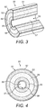
- FIG. 3 shows a partially cut-away perspective view of an example of another article for use with apparatus for heating smokable material to volatilize at least one component of the smokable material.
- FIG. 4 shows a schematic cross-sectional view of the article of FIG. 3 .
- FIG. 5 shows a partially cut-away perspective view of an example of an apparatus for heating smokable material to volatilize at least one component of the smokable material.
- FIG. 6 shows a partially cut-away perspective view of an example of another apparatus for heating smokable material to volatilize at least one component of the smokable material.
- FIG. 7 shows a perspective view of a heating device of the apparatus of FIG. 6 .
- the term “smokable material” includes materials that provide volatilized components upon heating, typically in the form of an aerosol.
- “Smokable material” may be a non-tobacco-containing material or a tobacco-containing material.
- “Smokable material” may, for example, include one or more of tobacco per se, tobacco derivatives, expanded tobacco, reconstituted tobacco, tobacco extract, homogenized tobacco or tobacco substitutes.
- the smokable material can be in the form of ground tobacco, cut rag tobacco, extruded tobacco, gel or agglomerates.
- “Smokable material” also may include other, non-tobacco, products, which, depending on the product, may or may not contain nicotine.
- polyimide refers to any polymer comprising or substantially formed of imide monomers and may be saturated or unsaturated.
- the polyimide may be hydrophobic.
- flavor and “flavorant” refer to materials which, where local regulations permit, may be used to create a desired taste or aroma in a product for adult consumers. They may include extracts (e.g., licorice, hydrangea, Japanese white bark magnolia leaf, chamomile, fenugreek, clove, menthol, Japanese mint, aniseed, cinnamon, herb, wintergreen, cherry, berry, peach, apple, Drambuie, bourbon, scotch, whiskey, spearmint, peppermint, lavender, cardamom, celery, cascarilla, nutmeg, sandalwood, bergamot, geranium, honey essence, rose oil, vanilla, lemon oil, orange oil, cassia, caraway, cognac, jasmine, ylang-ylang, sage, fennel, piment, ginger, anise, coriander, coffee, or a mint oil from any species of the genus Mentha
- annular means ring-shaped or in the form of a ring. “Annular” does not itself mean circular. In some embodiments, an element that is described herein as “annular” may indeed be circular, but in other embodiments the element may be “annular” and other than circular, such as elliptical or polygonal.
- FIGS. 1 and 2 there are shown a partially cut-away perspective view and a schematic cross-sectional view of an example of an article 40 according to an embodiment of the disclosure.
- the article 40 is adapted for use with apparatus having a power source and a heater which is engaged in use by the article 40 .
- the article 40 of this embodiment is particularly suitable for use with the apparatus 1 shown in FIG. 5 , described below.
- the article 40 of this embodiment comprises an annular body of smokable material 43 located around a body of porous aerosol containment material 44 .
- the body of porous aerosol containment material 44 is not formed of a smokable material.
- the body of porous aerosol containment material 44 comprises wadding or fleece, with a density of about 100 gsm or about 120 gsm.
- the body of porous aerosol containment material 44 is formed of one or more materials that do not contain aerosol-forming materials.
- the body of porous aerosol containment material 44 is formed of one or more materials that do contain aerosol-forming materials.
- the body of porous aerosol containment material 44 may for example be impregnated with smokable material, which may enhance aerosol production.
- the body of smokable material 43 is in contact with the body of porous aerosol containment material 44 , but in other embodiments there may be a further layer of material between the body of smokable material 43 and the body of porous aerosol containment material 44 .
- a further layer of material may increase the rigidity or robustness of the article 40 , may help retain the relative positions of the smokable material 43 and the porous aerosol containment material 44 , and/or may help hold different regions of the smokable material 43 together.
- An example such further layer of material is a layer of reconstituted tobacco paper.
- the body of porous aerosol containment material 44 is annular and is located around an air gap 46 of the article 40 .
- the air gap 46 follows an axis and permits volatilized material to pass out of the article 40 from the body of porous aerosol containment material 44 in use.
- the body of porous aerosol containment material 44 defines an inner surface 45 of the article 40 , so that a radially-inner surface 45 of the body of porous aerosol containment material 44 defines or delineates the air gap 46 .
- the air gap 46 is a through hole that extends from one side of the article 40 to an opposite side of the article 40 .
- the air gap 46 may be a blind hole that extends from only one side of the article 40 towards an opposite side of the article 40 .
- the air gap 46 may be omitted.
- the body of porous aerosol containment material 44 fills a space that is surrounded by the annular body of smokable material 43 .
- the body of porous aerosol containment material 44 may be cylindrical rather than annular, and in use volatilized material may pass out of the article 40 from an axial end of the body of porous aerosol containment material 44 .
- the article 40 of FIGS. 1 and 2 also comprises an annular body of thermally-conductive material 42 located around, and in contact with, the body of smokable material 43 .
- the body of thermally-conductive material 42 comprises a metal foil, such as aluminum foil, but in other embodiments the body of thermally-conductive material 42 may comprise one or more materials selected from the group consisting of: foil, paper, a polymer, a plastics material, and a combination of foil and paper, such as paper overlaid with foil, or the like.
- An example such paper is reconstituted tobacco paper.
- the body of thermally-conductive material 42 is for conducting heat from radially-outside of the article 40 to the body of smokable material 43 .
- the body of thermally-conductive material 42 may also increase the rigidity or robustness of the article 40 and/or may provide a substrate for the smokable material 43 so as to help hold different regions of the smokable material 43 together.
- the body of thermally-conductive material 42 defines an outer surface 41 of the article 40 .
- the body of thermally-conductive material 42 may be omitted.
- the body of smokable material 43 may define the outer surface 41 of the article 40 .
- axial ends of each of the body of smokable material 43 and the body of porous aerosol containment material 44 are visible at axial ends of the article 40 .
- one or both of the axial ends of the article 40 may comprise an end member (not shown) covering the axial ends of the body of smokable material 43 and/or of the body of porous aerosol containment material 44 .
- The, or each, end member may be formed by a radially-extending portion of the body of thermally-conductive material 42 .
- the article 40 of FIGS. 1 and 2 may be manufactured by the following method. First, an assembly comprising porous aerosol containment material, a layer of smokable material, and a layer of thermally-conductive material is provided. In the assembly, the porous aerosol containment material is on, and in contact with, the layer of smokable material. In turn, the layer of smokable material is on, and in contact with, the layer of thermally-conductive material.
- the assembly is bent or rolled so that: (a) the layer of thermally-conductive material becomes the annular body of thermally-conductive material 42 , (b) the layer of smokable material becomes the annular body of smokable material 43 , and (c) the porous aerosol containment material becomes the annular body of porous aerosol containment material 44 .
- the assembly may be rolled or bent around a spindle that is placed on the porous aerosol containment material of the assembly and ends up located in the air gap 46 of the article 40 . The spindle could be subsequently removed from the air gap 46 .
- the annular body of thermally-conductive material 42 defines the outer surface 41 of the article 40
- a radially-inner surface of the annular body of porous aerosol containment material 44 defines the air gap 46 .
- the skilled person would also be able to adapt the porous aerosol containment material of the assembly to ensure that, in the resultant article, the body of porous aerosol containment material 44 is cylindrical rather than annular. If the article is not to include the annular body of thermally-conductive material 42 , then, in the assembly, the layer of smokable material could be on, and in contact with, a substrate layer that is bent or rolled during the bending or rolling procedure and subsequently removed after the bending or rolling so that the body of smokable material 43 defines the outer surface 41 of the article.
- FIGS. 3 and 4 there are shown a partially cut-away perspective view and a schematic cross-sectional view of an example of another article 50 according to an embodiment of the disclosure.
- the article 50 of this embodiment is particularly suitable for use with the apparatus 2 shown in FIGS. 6 and 7 , described below.
- the article 50 of this embodiment comprises an annular first body of smokable material 53 located around a body of porous aerosol containment material 54 .
- the body of porous aerosol containment material 54 is not formed of a smokable material.
- the body of porous aerosol containment material 54 comprises wadding or fleece, with a density of about 100 gsm or about 120 gsm.
- the body of porous aerosol containment material 54 is formed of one or more materials that do not contain aerosol-forming materials.
- the body of porous aerosol containment material 54 is formed of one or more materials that do contain aerosol-forming materials.
- the body of porous aerosol containment material 54 may for example be impregnated with smokable material, which may enhance aerosol production.
- the first body of smokable material 53 is in contact with the body of porous aerosol containment material 54 , but in other embodiments there may be a further layer of material between the first body of smokable material 53 and the body of porous aerosol containment material 54 .
- Such a further layer of material may increase the rigidity or robustness of the article 50 , may help retain the relative positions of the smokable material of the first body of smokable material 53 and the body of porous aerosol containment material 54 , and/or may help hold different regions of the smokable material of the first body of smokable material 53 together.
- An example such further layer of material is a layer of reconstituted tobacco paper.
- the body of porous aerosol containment material 54 is annular and is located around an air gap 58 of the article 50 , although the body of porous aerosol containment material 54 does not itself define or delineate the air gap 58 , as will become apparent below.
- the article 50 of FIGS. 3 and 4 also comprises an annular first body of thermally-conductive material 52 located around, and in contact with, the first body of smokable material 53 .
- the first body of thermally-conductive material 52 comprises a metal foil, such as aluminum foil, but in other embodiments the first body of thermally-conductive material 52 may comprise any of the materials discussed above for the body of thermally-conductive material 52 of the article 40 of FIGS. 1 and 2 .
- the first body of thermally-conductive material 52 is for conducting heat from radially-outside of the article 50 to the first body of smokable material 53 .
- the first body of thermally-conductive material 52 may also increase the rigidity or robustness of the article 50 and/or may provide a substrate for the smokable material of the first body of smokable material 53 so as to help hold different regions of the smokable material together.
- the first body of thermally-conductive material 52 defines an outer surface 51 of the article 50 .
- the first body of thermally-conductive material 52 may be omitted.
- the first body of smokable material 53 may define the outer surface 51 of the article 50 .
- the article 50 of FIGS. 3 and 4 also comprises a second body of smokable material 55 .
- the annular body of porous aerosol containment material 54 is located around, and is in contact with, the second body of smokable material 55 .
- such a further layer of material could be made from reconstituted tobacco paper, and/or could provide any of the advantages discussed above for the optional further layer of material between the first body of smokable material 53 and the body of porous aerosol containment material 54 .
- the smokable material of the first body of smokable material 53 has a form and chemical composition that is the same as the form and chemical composition, respectively, of the smokable material of the second body of smokable material 55 .
- the smokable material of the first body of smokable material 53 may have a form or chemical composition that differs from the form or chemical composition, respectively, of the smokable material of the second body of smokable material 55 .
- the smokable material of one of the first and second bodies of smokable material 53 , 55 has a form so as to be heatable more quickly, for example to volatilize at least one component of the smokable material, than the smokable material of the other of the first and second bodies of smokable material 53 , 55 .
- the smokable material of the first and second bodies of smokable material 53 , 55 may have different mean particle sizes.
- the smokable material of one of the first and second bodies of smokable material 53 , 55 may comprise particles of the smokable material having a first mean particle size
- the smokable material of the other of the first and second bodies of smokable material 53 , 55 may comprise particles of the smokable material having a second mean particle size that is greater than the first mean particle size.
- particles of the smokable material having a smaller mean particle size are heatable more quickly, for example to volatilize at least one component of the smokable material, by a given heat source than are particles of the smokable material having a greater mean particle size.
- the smokable material of the first body of smokable material 53 may have a different chemical composition to the smokable material of the second body of smokable material 55 . That is, the ingredient or ingredients of the first body of smokable material 53 may be different to that or those of the second body of smokable material 55 .
- the smokable material of one of the first and second bodies of smokable material 53 , 55 comprises an aerosol forming agent, such as glycerol, and the smokable material of the other of the first and second bodies of smokable material 53 , 55 is free or substantially free of the aerosol forming agent.
- heating of one or other of the first and second bodies of smokable material 53 , 55 may be provided by the apparatus 1 , thus enabling a user to select which of the first and second bodies of smokable material 53 , 55 is to be used to create aerosol for their inhalation.
- the difference in chemical composition between the first and second bodies of smokable material 53 , 55 may comprise a difference in quantities by weight of a smoke modifying substance, such as a flavorant, in each of the first and second bodies 53 , 55 , as a percentage of a total weight of the smokable material of the respective first and second bodies 53 , 55 .
- a smoke modifying substance such as a flavorant
- the smokable material of one of the first and second bodies of smokable material 53 , 55 may comprise a flavorant
- the smokable material of the other of the first and second bodies of smokable material 53 , 55 may be free, or substantially free, of the flavorant.
- one of the first and second bodies of smokable material 53 , 55 may comprise a first flavorant, and the other of the first and second bodies of smokable material 53 , 55 may comprise a second flavorant that is different to the first flavorant.
- the article 50 of FIGS. 3 and 4 further comprises an annular second body of thermally-conductive material 56 .
- the second body of smokable material 55 is located around, and is in contact with, the second body of thermally-conductive material 56 .
- the second body of thermally-conductive material 56 comprises a metal foil, such as aluminum foil, but in other embodiments the second body of thermally-conductive material 56 may comprise any of the materials discussed above for the body of thermally-conductive material 42 of the article 40 of FIGS. 1 and 2 .
- the second body of thermally-conductive material 56 is for conducting heat from radially-inside of the article 50 to the second body of smokable material 55 .
- the second body of thermally-conductive material 56 may also increase the rigidity or robustness of the article 50 and/or may provide a substrate for the smokable material of the second body of smokable material 55 so as to help hold different regions of the smokable material together.
- the second body of thermally-conductive material 56 defines an inner surface 57 of the article 50 , so that a radially-inner surface 57 of the second body of thermally-conductive material 56 defines or delineates the air gap 58 .
- the air gap 58 follows an axis and receives the first heater 22 of the apparatus 2 in use.
- the air gap 58 is a through hole that extends from one side of the article 50 to an opposite side of the article 50 .
- the air gap 58 may be a blind hole that extends from only one side of the article 50 towards an opposite side of the article 50 .
- the second body of thermally-conductive material 56 may be omitted.
- a radially-inner surface of the second body of smokable material 55 may define the inner surface 57 of the article 50 and the air gap 58 .
- each of the first and second bodies of smokable material 53 , 55 and the body of porous aerosol containment material 54 are visible at axial ends of the article 50 .
- one or both of the axial ends of the article 50 may comprise an end member (not shown) covering the axial ends of the first and second bodies of smokable material 53 , 55 and/or the body of porous aerosol containment material 54 .
- The, or each, end member may be formed by a radially-extending portion of the first body of thermally-conductive material 52 .
- the article 50 discussed above is an embodiment of an article comprising an annular body of the alternative material, an annular first body of smokable material located around the body of material, and an annular second body of smokable material, wherein the body of the alternative material is located around the second body of smokable material.
- the porous aerosol containment material may be replaced by an alternative material that is not necessarily porous and/or suitable for aerosol containment.
- Some such resultant articles may include the first and/or second bodies of thermally-conductive material 52 , 56 , whereas the first and second bodies of thermally-conductive material 52 , 56 may be omitted from other such resultant articles.
- the article 50 of FIGS. 3 and 4 may be manufactured by the following method. First, an assembly comprising porous aerosol containment material, first and second layers of smokable material, and first and second layers of thermally-conductive material is provided. In the assembly, the second layer of thermally-conductive material is on, and in contact with, the second layer of smokable material. The second layer of smokable material is on, and in contact with, the porous aerosol containment material. The porous aerosol containment material is on, and in contact with, the first layer of smokable material. The first layer of smokable material is on, and in contact with, the first layer of thermally-conductive material.
- the assembly is bent or rolled so that: (a) the first layer of thermally-conductive material becomes the annular first body of thermally-conductive material 52 , (b) the first layer of smokable material becomes the annular first body of smokable material 53 , (c) the porous aerosol containment material becomes the annular body of porous aerosol containment material 54 , (d) the second layer of smokable material becomes the annular second body of smokable material 55 , and (e) the second layer of thermally-conductive material becomes the annular second body of thermally-conductive material 56 .
- the assembly may be bent or rolled around a spindle that is placed on the second layer of thermally-conductive material of the assembly and ends up located in the air gap 58 of the article 50 .
- the spindle could be subsequently removed from the air gap 58 .
- the annular first body of thermally-conductive material 52 defines the outer surface 51 of the article 50
- a radially-inner surface of the annular second body of thermally-conductive material 56 defines the air gap 58 .
- the skilled person would readily understand from the present disclosure how to adapt this method of manufacturing the article 50 of FIGS. 3 and 4 so as to manufacture one of the above-described variations on the article 50 .
- the first layer of thermally-conductive material may be oversized as compared to the other layers of material in the assembly so that, after the bending or rolling procedure, protruding portions of the first body of thermally-conductive material 52 may be folded to form radially-extending end members of the first body of thermally-conductive material 52 , which end members cover the axial ends of the first and second bodies of smokable material 53 , 55 and the body of porous aerosol containment material 54 .
- the article 40 , 50 has a circular circumference in a plane perpendicular to an axis of the annular body of smokable material 43 , 53 .
- the circumference may be other than circular, such as elliptical or polygonal.
- various elements of the article 40 , 50 are described as being “annular”.
- each of these elements is annular and circular.
- one or more of these elements may be annular and other than circular, such as elliptical or polygonal.
- the smokable material comprises tobacco.
- the smokable material may consist of tobacco, may consist substantially entirely of tobacco, may comprise tobacco and smokable material other than tobacco, may comprise smokable material other than tobacco, or may be free of tobacco.
- the smokable material may include an aerosol forming agent, such as glycerol.
- the porous aerosol containment material is a porous material for the containment of aerosol generated in the article 40 , 50 by heating the smokable material.
- the porous aerosol containment material comprises wadding or fleece with a density of about 100 gsm or about 120 gsm. In other embodiments, the density of the porous aerosol containment material may be different. However, if the density is too high, the porous aerosol containment material may act as a filter and attenuate generated aerosol. Alternatively, if the density is too low, the porous aerosol containment material may not provide effective aerosol containment.
- An appropriate density, particularly when the porous aerosol containment material comprises wadding or fleece, may be between about 60 and about 140 gsm, or between about 80 and about 120 gsm.
- the aerosol containment material may have a thickness within a range of 1 mm to 2 mm.
- the porous aerosol containment material may comprise one or more porous materials selected from the group consisting of: wadding, fleece, non-woven material, non-woven fleece, woven material, knitted material, nylon, foam, polystyrene, polyester, polyester filament, polypropylene, and a blend of polyester and polypropylene.
- a material other than wadding or fleece is used, the material would have a density chosen to have similar thermal properties to wadding or fleece having a density of from about 80 to about 120 gsm.
- the porous aerosol containment material is free of smokable material. However, this need not always be the case.
- the body of porous aerosol containment material is heat resistant at least over the expected range of temperatures of the heating device 20 of the apparatus 1 that will arise in operation, such as for example 150 to 300 degrees Celsius or 170 to 220 degrees Celsius as discussed below, and will not degrade when subjected to such operation temperatures.
- the porous aerosol containment material helps to ensure that volatilized material generated in the article 40 , 50 in use does not condense on an inner surface of the recess 13 of the apparatus 1 .
- the provision of the body of porous aerosol containment material helps to increase the surface area on which aerosol generated in the article 40 , 50 in use may form.
- such a body of porous aerosol containment material helps to increase the amount of visible aerosol generated in, or emitted from, the article 40 , 50 in use, and thus may enhance the consumer experience.
- the article 40 , 50 is a consumable article. Once all, or substantially all, of the volatile component(s) of the smokable material in the article 40 , 50 has/have been spent, the user may remove the article 40 , 50 from the apparatus 1 and dispose of the article 40 , 50 . The user may subsequently mate another, unspent article 40 , 50 with the interface 13 of the apparatus 1 and re-use the apparatus 1 .
- the articles 40 , 50 may be non-consumable articles, and the combination of the apparatus 1 and the article 40 , 50 may be disposed of together once the volatile component(s) of the smokable material in the article 40 , 50 has/have been spent.
- FIG. 5 there is shown a partially cut-away perspective view of an example of an apparatus 1 for heating smokable material to volatilize at least one component of the smokable material.
- the apparatus is particularly suitable for use with the article 40 discussed above with reference to FIGS. 1 and 2 .
- the apparatus 1 is arranged to heat the smokable material in the article 40 to volatilize at least one component of the smokable material without combusting, or burning, the smokable material.
- the apparatus 1 comprises a body 10 and a mouthpiece 30 .
- the outward appearance of the apparatus 1 when assembled is defined by the combination of the body 10 and the mouthpiece 30 .
- the body 10 is generally tubular and elongate, has first and second opposite longitudinal ends 11 , 12 , and defines an interface for co-operating with the article 40 .
- the interface comprises a recess 13 for receiving the article 40 .
- the interface can take a different form, such as a shelf, a surface, or a projection, and optionally requires mechanical mating with the article 40 in order to co-operate with the article 40 .
- the first longitudinal end 11 of the body 10 defines an opening 14 into the recess 13 at a first end of the recess 13 .
- the opening 14 is shaped and sized so that the article 40 is movable through the opening 14 to allow a user to insert the article 40 into the recess 13 and/or to remove the article 40 from the recess 13 , as will be described in more detail below.
- the body 10 houses electrical components of the apparatus 1 .
- the electrical components in this embodiment comprise an electrical power source 15 , a controller 16 , an actuator 17 , and a heating device 20 .
- the mouthpiece 30 is generally tubular and elongate and has first and second opposite longitudinal ends 31 , 32 .
- the mouthpiece 30 comprises an inlet 34 at the second longitudinal end 32 of the mouthpiece 30 , an outlet 35 at the first longitudinal end 31 of the mouthpiece 30 , and a channel 36 fluidly connecting the inlet 34 with the outlet 35 .
- the second longitudinal end 32 of the mouthpiece 30 comprises a connector (not shown) that is releasably engageable with a connector (not shown) of the first longitudinal end 11 of the body 10 , so as to connect the mouthpiece 30 to the body 10 .
- the mouthpiece 30 and the body 10 may be permanently connected, such as through a hinge or flexible member.
- the mouthpiece 30 is locatable relative to the body 10 so as to cover the opening 14 into the recess 13 .
- the first longitudinal end 31 of the mouthpiece 30 forms the first longitudinal end of the apparatus 1
- the channel 36 of the mouthpiece 30 is in fluid communication with the recess 13 via the inlet 34 of the mouthpiece 30 .
- the mouthpiece 30 includes a feature that would contact the article 40 when the article 40 is in the recess 13 , to press the article 40 into the recess 13 and help ensure that the article 40 is correctly positioned relative to the heating device 20 .
- the heating device 20 comprises a tubular heater 21 that surrounds the recess 13 .
- the heater 21 has an annular cross-sectional shape in a plane perpendicular to an axis of the heater 21 , and a radially-inner surface of the heater 21 defines the radial extent of the recess 13 .
- the recess 13 is thus coaxial with the heater 21 .
- the heating device 20 is attached to a retainer 18 that is fixed to the body 10 so as to retain the heater 21 in position relative to the body 10 .
- the heater 21 extends from a second end of the recess 13 to the first end of the recess 13 , and an axial end of the heater 21 defines the opening 14 into the recess 13 .
- the heater 21 extends along the full axial length of the recess 13 .
- the recess 13 may be partially defined by the heater 21 and partially defined by one or more other sections of the body 10 .
- the opening 14 into the recess 13 is defined by a section of the body 10 other than the heater 21 .
- the heater 21 comprises electrically-conductive material.
- the electrically-conductive material is copper, but in other embodiments the electrically-conductive material may comprise any one or more of a metal, a metal alloy, steel, stainless steel, copper and nichrome.
- the electrically-conductive material has been etched in such a manner as to be patterned to provide electrically-conductive tracks.
- the electrically-conductive material may be printed in such a manner as to be patterned, or may be patterned by some other process.
- the electrically-conductive material may be non-patterned.
- the electrically-conductive material may be a simple tubular length of the electrically-conductive material.
- the heater 21 is heatable by passing an electric current through the electrically-conductive material.
- a cross sectional area and length of an electric current flow-path in the electrically-conductive material are set, so that heating of the heater 21 can be achieved by passing a predetermined electric current through the electrically-conductive material.
- the heater 21 also comprises a support for supporting the electrically-conductive material.
- the support is an electrical insulator and is resistant to heat. More particularly, the support is resistant to heat at least over the expected range of temperatures of the heater 21 that will arise in operation, such as for example 150 to 300 degrees Celsius or 170 to 220 degrees Celsius.
- the support is a ceramic, but in other embodiments the support may be made from another material, such as polyimide.
- the controller 16 is in some embodiments arranged to ensure that the heater 21 is heated to a temperature within this range. Accordingly, the support is able to withstand the heating of the electrically-conductive material during use of the apparatus 1 .
- the electrical power source 15 is a rechargeable battery. In other embodiments, the electrical power source 15 may be other than a rechargeable battery, such as a non-rechargeable battery or a capacitor.
- the controller 16 comprises an integrated circuit (IC), such as an IC on a printed circuit board (PCB). In other embodiments, the controller 16 may take a different form.
- the controller 16 is for controlling the supply of electrical power from the electrical power source 15 to the heating device 20 .
- the controller 16 is operated in this embodiment by user-actuation of the actuator 17 .
- the actuator 17 is located at the exterior of the body 10 and takes the form of a push-button. In other embodiments, a different form of actuator 17 may be provided, such as a toggle switch, a dial, or the like. Actuation of the actuator 17 by a user causes the controller 16 to cause an electric current to be applied across the electrically-conductive material of the heater 21 of the heating device 20 .
- Such actuation of the actuator 17 may cause completion of an electrical circuit in the controller 15 .
- the heater 21 heats up.
- the electrical resistance of the electrically-conductive material changes as the temperature of the heater 21 increases.
- the controller 16 monitors the electrical resistance of the heated electrically-conductive material, and then adjusts the magnitude of the electrical current applied across the electrically-conductive material on the basis of the monitored electrical resistance as necessary, in order to ensure that the temperature of the heater remains within the above-discussed temperature range of about 150 degrees Celsius to about 300 degrees Celsius, or about 170 degrees Celsius to about 220 degrees Celsius.
- the smokable material in the article 40 is heated sufficiently to volatilize at least one component of the smokable material without combusting the smokable material. Accordingly, the controller 16 , and the apparatus 1 as a whole, is arranged to heat the smokable material to volatilize the at least one component of the smokable material without combusting the smokable material. In other embodiments, the temperature range of heating may be other than this range.
- the body 10 has an inlet for admitting air into the apparatus 1 from an exterior of the apparatus 1
- the retainer 18 has a hole therethrough which places the recess 13 in fluid communication with the inlet. Therefore, when the mouthpiece 30 is connected to the body 10 to assemble the apparatus 1 , there is defined an overall flow path that extends from the exterior of the apparatus 1 , then through the inlet, then through the hole in the retainer 18 , then through the recess 13 , then through the channel 36 of the mouthpiece 30 to the exterior of the apparatus 1 .
- a user ensures that the mouthpiece 30 is at a location relative to the body 10 at which the article 40 is movable through the opening 14 .
- the user then passes the article 40 through the opening 14 and into the recess 13 , so as to locate the article 40 within the tubular heater 21 .
- the user then moves the mouthpiece 30 relative to the body 10 to a location at which the mouthpiece 30 covers the opening 14 , with the first longitudinal end 31 of the mouthpiece 30 forming the first longitudinal end of the apparatus 1 , and with the channel 36 of the mouthpiece 30 in fluid communication with the recess 13 via the inlet 34 of the mouthpiece 30 .
- the mouthpiece 30 is retained at this location through engagement of the connector of the mouthpiece 30 with the connector of the body 10 .
- the controller 16 When the actuator 17 is subsequently actuated by the user, the controller 16 is operated to cause an electric current to be applied across the electrically-conductive material of the heater 21 . This application of the electric current causes the heater 21 to heat up so as to heat the body of smokable material 43 of the article. This causes at least one component of the smokable material to volatilize without combusting the smokable material.
- the user draws on the outlet 35 of the mouthpiece 30 . This causes a reduction in pressure in the recess 13 , which causes air to be drawn into the recess 13 via the inlet of the body 10 and the hole in the retainer 18 , in turn.
- this causes the volatilized component(s) of the smokable material 43 to be cooled, so that they condense to form an aerosol.
- the body of porous aerosol containment material 44 contains the aerosol generated, so as to help avoid the aerosol condensing on an inner surface of the recess 13 .
- the user's continued drawing causes the aerosol to be drawn from the recess 13 and/or from the body of porous aerosol containment material 44 and into the user's mouth via the channel 36 of the mouthpiece 30 . Each time air is drawn into the recess 13 , aerosol is produced. This can be repeated until the volatile component(s) of the smokable material 43 are exhausted.
- the user may move the mouthpiece 30 relative to the body 10 to a location at which the article 40 is movable through the opening 14 .
- the user may then remove the article 40 from the recess 13 via the opening 14 .
- the user can subsequently insert another, unspent article 40 into the recess 13 and repeat the above process.
- FIG. 6 there is shown a partially cut-away perspective view of another example of an apparatus 2 for heating smokable material to volatilize at least one component of the smokable material.
- the apparatus 2 is particularly suitable for use with the article 50 discussed above with reference to FIGS. 3 volatilize 4 .
- the apparatus 2 is arranged to heat the smokable material in the article 50 to volatilize at least one component of the smokable material without combusting, or burning, the smokable material.
- the apparatus 2 of this embodiment is identical to the apparatus 1 shown in FIG. 5 and discussed above, except for the form of the heating device 20 and the controller 16 .
- the heating device 20 of the apparatus of FIG. 6 is shown in more detail in FIG. 7 .
- the heating device 20 comprises a first heater 22 extending along an axis, and a second heater 23 spaced from and at least partially surrounding the first heater 22 .
- the second heater 23 is tubular and surrounds part of the recess 13 .
- the second heater 23 has a cross-sectional shape in a plane perpendicular to the axis that is annular and circular, and a radially-inner surface of the second heater 23 defines the radial extent of the part of the recess 13 .
- the cross-sectional shape of the second heater 23 may be annular and other than circular, such as elliptical or polygonal, or the cross-sectional shape of the second heater 23 may be other than annular, such as an arc of a circle or semi-circular.
- the second heater 23 is coaxial with the first heater 22 , but in other embodiments this may not be true.
- the first heater 22 projects into the recess 13 and has a circular cross-sectional shape in a plane perpendicular to the axis.
- the first heater 22 may have a cross-sectional shape other than circular, such as elliptical or polygonal.
- the apparatus 2 of FIG. 6 is particularly suitable for use with article 50 discussed above with reference to FIGS. 3 and 4 .
- the first heater 22 has a first length in a direction parallel to the axis
- the second heater 23 has a second length in a direction parallel to the axis
- the second length is less than the first length.
- the first and second lengths are measured from a plane that is perpendicular to the axis.
- each of the first and second heaters 22 , 23 has an axial end that lies in the plane.
- each of the first and second heaters 22 , 23 may have axial ends that are not coplanar with the axial ends of the other of the first and second heaters 22 , 23 .
- the heating device 20 comprises a retainer 18 that is fixed to the body 10 and retains the first and second heaters 22 , 23 in position relative to the body 10 .
- the retainer 18 has a hole therethrough which places the recess 13 in fluid communication with the inlet of the body 10 .
- the recess 13 is partially defined by the second heater 23 and partially defined by a section of the body 10 .
- the opening 14 into the recess 13 is defined by a section of the body 10 other than the heating device 20 .
- each of the first and second heaters 22 , 23 extends from a second end of the recess 13 towards the first end of the recess 13 , but the second heater 23 does not extend as far as the opening 14 whereas the first heater 22 extends through the opening 14 .
- a distal end of the first heater 22 which distal end is distal from the retainer 18 , is located within the mouthpiece 30 .
- the second heater 23 may extend along the full axial length of the recess 13 , and/or an axial end of the second heater 23 may define the opening 14 into the recess 13 .
- each of the first and second heaters 22 , 23 comprises electrically-conductive material and a support for supporting the electrically-conductive material.
- the electrically-conductive material and the support may be of any of the materials and forms described above for the electrically-conductive material and the support of the heater 21 of the apparatus 1 of FIG. 5 , and so further detail will not be included here.
- the controller 16 of the apparatus 2 of FIG. 6 is for controlling the supply of electrical power from the electrical power source 15 to the heating device 20 .
- the controller 16 of the apparatus 2 of FIG. 6 is for controlling the supply of electrical power from the electrical power source 15 to the first heater 22 independently of the supply of electrical power from the electrical power source 15 to the second heater 23 .
- the controller 16 may, for example, cause the controller 16 to cause a first electric current to be applied across the electrically-conductive material of one of the first and second heaters 22 , 23 , and then subsequently to cause a second electric current to be applied across the electrically-conductive material of the other of the first and second heaters 22 , 23 .
- the second electric current may be applied while the first electric current is applied, or after the first electric current has ceased to be applied.
- the manner in which the controller 16 causes electric currents to be applied across the electrically-conductive material of the first and second heaters 22 , 23 may be selectable by a user, such as through the user's suitable actuation of the actuator 17 in one of a plurality of possible ways.
- the actuator 17 may be actuatable by a user in a plurality of different ways, each of which ways causes the controller 16 to cause operation of the heating device 20 in a different predetermined manner.
- a user may be able to select which of the first and second heaters 22 , 23 is to be heated, and thus which of the first and second bodies of smokable material 53 , 55 is to be heated.
- first and second bodies of smokable material 53 , 55 are heatable at different rates by a given heat source, or comprise different smoke modifying agents or flavorants, a user is thus able to select or configure the type of aerosol they wish to generate, and thus the experience they wish to have on inhaling the aerosol.
- the electrical resistance of the electrically-conductive material of the first and second heaters 22 , 23 changes as the temperature of the first and second heaters 22 , 23 increases.
- the controller 16 monitors the electrical resistance of the heated electrically-conductive material, and then adjusts the magnitude of the electrical current applied across the electrically-conductive material on the basis of the monitored electrical resistance as necessary, in order to ensure that the temperature of the heater(s) remains within the above-discussed temperature range of about 150 degrees Celsius to about 300 degrees Celsius, or about 170 degrees Celsius to about 220 degrees Celsius.
- the smokable material in the article 50 is heated sufficiently to volatilize at least one component of the smokable material without combusting the smokable material. Accordingly, the controller 16 , and the apparatus 2 as a whole, is arranged to heat the smokable material to volatilize the at least one component of the smokable material without combusting the smokable material. In other embodiments, the temperature range of heating may be other than this range.
- a user slides the first heater 22 into the air gap 58 of the article 50 , and passes the article 50 through the opening 14 and into the recess 13 , so as to locate the article 50 within the tubular second heater 23 .
- the user then moves the mouthpiece 30 relative to the body 10 to a location at which the mouthpiece 30 covers the opening 14 , as described above for the apparatus 1 of FIG. 5 .
- the controller 16 When the actuator 17 is subsequently actuated by the user, the controller 16 is operated to cause an electric current to be applied across the electrically-conductive material of the heating device 20 . This application of the electric current causes the first and/or second heater 22 , 23 to heat up so as to heat the first and second bodies of smokable material 53 , 55 of the article 50 .
- the first heater 22 When the first heater 22 is in the air gap 58 of the article 50 , the first heater 22 is closer to the second body of smokable material 55 than to the first body of smokable material 53 , and the second heater 23 is closer to the first body of smokable material 53 than to the second body of smokable material 55 .
- the first heater 22 is predominantly for heating the second body of smokable material 55
- the second heater 23 is predominantly for heating the first body of smokable material 53 .
- the heating of the first and/or second heater 22 , 23 causes at least one component of the smokable material to volatilize without combusting the smokable material.
- the body of porous aerosol containment material 54 contains aerosol generated following volatilization of the component(s) of the smokable material, so as to help avoid the aerosol condensing on an inner surface of the recess 13 of the apparatus 2 .
- the user inhales the aerosol by drawing on the outlet 35 of the mouthpiece 30 , as described above for the apparatus 1 of FIG. 5 .
- the user may remove the article 50 from the recess 13 via the opening 14 and insert another, unspent article 50 into the recess 13 and repeat the above process.
- the temperature of the heater(s) 21 , 22 , 23 may be controlled in a different manner.
- the controller 16 may monitor a current flow through the electrically-conductive material, or an output from a sensor for sensing a temperature of, or proximate, the heater(s) 21 , 22 , 23 , and then adjust the magnitude of the electrical current applied across the electrically-conductive material on the basis of the monitored current flow as necessary, in order to ensure that the temperature of the heater remains within the above-discussed temperature range.
- Other ways of controlling the temperature of the heater(s) 21 , 22 , 23 could be used in other embodiments.
- any one of the apparatuses 1 , 2 discussed above may be sold, supplied or otherwise provided separately from the article(s) 40 , 50 with which the apparatus 1 , 2 is particularly suitable for use.
- one of the apparatuses 1 , 2 and one or more of the articles 40 , 50 may be provided together as a kit.
Landscapes
- Chemical & Material Sciences (AREA)
- Chemical Kinetics & Catalysis (AREA)
- General Chemical & Material Sciences (AREA)
- Thermotherapy And Cooling Therapy Devices (AREA)
- Cigarettes, Filters, And Manufacturing Of Filters (AREA)
- Catching Or Destruction (AREA)
- Colloid Chemistry (AREA)
- Resistance Heating (AREA)
- Heating, Cooling, Or Curing Plastics Or The Like In General (AREA)
- Manufacture Of Tobacco Products (AREA)
- Food Preservation Except Freezing, Refrigeration, And Drying (AREA)
- Disinfection, Sterilisation Or Deodorisation Of Air (AREA)
- Medicinal Preparation (AREA)
Applications Claiming Priority (3)
| Application Number | Priority Date | Filing Date | Title |
|---|---|---|---|
| GB1505593.2 | 2015-03-31 | ||
| GBGB1505593.2A GB201505593D0 (en) | 2015-03-31 | 2015-03-31 | Article for use with apparatus for heating smokable material |
| PCT/EP2016/057097 WO2016156510A2 (en) | 2015-03-31 | 2016-03-31 | Apparatus for heating smokable material, article for use therewith and method of manufacture of article |
Publications (2)
| Publication Number | Publication Date |
|---|---|
| US20180338520A1 US20180338520A1 (en) | 2018-11-29 |
| US10863766B2 true US10863766B2 (en) | 2020-12-15 |
Family
ID=53178481
Family Applications (1)
| Application Number | Title | Priority Date | Filing Date |
|---|---|---|---|
| US15/563,065 Active 2037-04-10 US10863766B2 (en) | 2015-03-31 | 2016-03-31 | Apparatus for heating smokable material, article for use therewith and method of manufacture of article |
Country Status (8)
| Country | Link |
|---|---|
| US (1) | US10863766B2 (ru) |
| EP (2) | EP3277114A2 (ru) |
| JP (4) | JP6553204B2 (ru) |
| CN (1) | CN107427088A (ru) |
| GB (1) | GB201505593D0 (ru) |
| HK (1) | HK1248073A1 (ru) |
| RU (2) | RU2019143566A (ru) |
| WO (1) | WO2016156510A2 (ru) |
Cited By (5)
| Publication number | Priority date | Publication date | Assignee | Title |
|---|---|---|---|---|
| WO2022167580A1 (en) * | 2021-02-08 | 2022-08-11 | Jt International S.A. | Aerosol generating article |
| US20220330604A1 (en) * | 2015-09-25 | 2022-10-20 | Schweitzer-Mauduit International, Inc. | Reconstituted Tobacco For Devices That Heat Tobacco Without Burning It |
| WO2024104962A1 (en) * | 2022-11-14 | 2024-05-23 | Fraunhofer-Gesellschaft zur Förderung der angewandten Forschung e.V. | Device and method for vaporizing a liquid for an electric cigarette |
| US12011047B2 (en) | 2018-09-18 | 2024-06-18 | Airgraft Inc. | Methods and systems for vaporizer security and traceability management |
| US12063981B2 (en) | 2019-08-13 | 2024-08-20 | Airgraft Inc. | Methods and systems for heating carrier material using a vaporizer |
Families Citing this family (33)
| Publication number | Priority date | Publication date | Assignee | Title |
|---|---|---|---|---|
| GB201423318D0 (en) * | 2014-12-29 | 2015-02-11 | British American Tobacco Co | Cartridge for use with apparatus for heating smokable material |
| GB201423317D0 (en) | 2014-12-29 | 2015-02-11 | British American Tobacco Co | Apparatus for heating smokable material |
| GB201423312D0 (en) * | 2014-12-29 | 2015-02-11 | British American Tobacco Co | Heating device for apparatus for heating smokable material and method of manufacture |
| GB2547699B (en) * | 2016-02-26 | 2021-09-22 | Nerudia Ltd | Aerosol delivery system |
| US11477861B2 (en) | 2017-05-10 | 2022-10-18 | Philip Morris Products S.A. | Aerosol-generating article, device and system for use with a plurality of aerosol-forming substrates |
| WO2018235241A1 (ja) * | 2017-06-22 | 2018-12-27 | 日本たばこ産業株式会社 | 香味発生セグメント、ならびにこれを備える香味発生物品および香味吸引システム |
| KR102696113B1 (ko) * | 2017-06-28 | 2024-08-20 | 필립모리스 프로덕츠 에스.에이. | 연소 없이 공기를 예열하는 시샤 장치 |
| CA3099009A1 (en) | 2018-05-21 | 2019-11-28 | Jt International Sa | Aerosol generating articles and methods for manufacturing the same |
| WO2019224068A1 (en) | 2018-05-21 | 2019-11-28 | Jt International Sa | An aerosol generating article, a method for manufacturing an aerosol generating article and an aerosol generating system |
| GB201810738D0 (en) * | 2018-06-29 | 2018-08-15 | Nicoventures Trading Ltd | An aerosol generating component for a tobacco heating device and mouthpiece therefor |
| GB201812498D0 (en) * | 2018-07-31 | 2018-09-12 | Nicoventures Holdings Ltd | Aerosol generation |
| GB201812502D0 (en) * | 2018-07-31 | 2018-09-12 | Nicoventures Holdings Ltd | Aerosol generation |
| WO2020044181A1 (en) * | 2018-08-30 | 2020-03-05 | Philip Morris Products S.A. | Aerosol-generating article with absorbent carrier |
| CN110495640A (zh) * | 2018-09-17 | 2019-11-26 | 苏州晶品新材料股份有限公司 | 三维网状储油雾化体 |
| CN113163869A (zh) * | 2018-12-10 | 2021-07-23 | 日本烟草产业株式会社 | 非燃烧加热型吸烟装置 |
| KR20210101215A (ko) * | 2018-12-17 | 2021-08-18 | 필립모리스 프로덕츠 에스.에이. | 에어로졸 발생 물품과 함께 사용하기 위한 관형 요소를 제조하는 시스템, 장치 및 방법 |
| CN113260262A (zh) * | 2018-12-17 | 2021-08-13 | 菲利普莫里斯生产公司 | 用于与气溶胶生成制品一起使用的包括多孔介质和包装物的管状元件 |
| CN113490428A (zh) * | 2018-12-17 | 2021-10-08 | 菲利普莫里斯生产公司 | 用于与气溶胶生成制品一起使用的包含多孔介质的管状元件 |
| CN109645573B (zh) * | 2019-01-23 | 2024-04-02 | 中国科学技术大学 | 一种用于低温不燃烧香烟的外围刺入式加热设备 |
| EP3937681A4 (en) * | 2019-03-11 | 2023-03-22 | Selby, Ryan Daniel | IMPROVED SMOKING ARTICLE |
| CN113710110A (zh) * | 2019-04-18 | 2021-11-26 | 日本烟草产业株式会社 | 加热式香烟 |
| CN113710108A (zh) * | 2019-04-18 | 2021-11-26 | 日本烟草产业株式会社 | 加热式香烟 |
| WO2020213144A1 (ja) * | 2019-04-18 | 2020-10-22 | 日本たばこ産業株式会社 | 非燃焼加熱式たばこ及び電気加熱式たばこ製品 |
| JP7464574B2 (ja) * | 2019-04-18 | 2024-04-09 | 日本たばこ産業株式会社 | 加熱式たばこ |
| GB201907702D0 (en) * | 2019-05-30 | 2019-07-17 | Nicoventures Trading Ltd | Aerosol generation |
| WO2020254569A1 (en) * | 2019-06-21 | 2020-12-24 | Jt International Sa | Aerosol-generating article comprising an aerosol-generating material supported by a carrier element |
| JP7307852B2 (ja) * | 2019-09-19 | 2023-07-12 | フィリップ・モーリス・プロダクツ・ソシエテ・アノニム | 管状基体層を備えた中空のエアロゾル発生物品 |
| JP2023503504A (ja) * | 2019-11-29 | 2023-01-30 | ニコベンチャーズ トレーディング リミテッド | 非燃焼型エアロゾル供給デバイス用の2つの異なるエアロゾル生成材料を備える消耗品 |
| CN111567858B (zh) * | 2020-05-11 | 2022-06-14 | 贵州中烟工业有限责任公司 | 一种加热不燃烧发烟体的制造方法 |
| WO2022230867A1 (ja) * | 2021-04-27 | 2022-11-03 | 日本たばこ産業株式会社 | 非燃焼加熱型香味吸引器用たばこシート、非燃焼加熱型香味吸引器、及び非燃焼加熱型香味吸引システム |
| KR20240001712A (ko) * | 2021-05-13 | 2024-01-03 | 니뽄 다바코 산교 가부시키가이샤 | 비연소 가열 향미 흡인 물품 및 비연소 가열 향미 흡인 시스템 |
| EP4309525A1 (en) * | 2022-07-20 | 2024-01-24 | Ysq International Pte. Ltd. | Consumable cartridge, aerosol-generating device and method of manufacturing the consumable cartridge |
| WO2024126803A1 (en) * | 2022-12-15 | 2024-06-20 | Philip Morris Products S.A. | Improved aerosol-generating article, device and system |
Citations (114)
| Publication number | Priority date | Publication date | Assignee | Title |
|---|---|---|---|---|
| US2057353A (en) | 1936-10-13 | Vaporizing unit fob therapeutic | ||
| DE822964C (de) | 1949-10-18 | 1951-11-29 | Rudi Muencheberg | Fuellungen fuer Tabakpfeifen |
| US2937648A (en) | 1958-01-22 | 1960-05-24 | John K Meyer | Tobacco pellet or cartridge |
| US2991788A (en) | 1959-03-23 | 1961-07-11 | Alvin O Brost | Pipettes-tobacco packets |
| US3148996A (en) | 1962-03-26 | 1964-09-15 | Horizons Inc | Foamed ceramic |
| US3844199A (en) | 1968-09-27 | 1974-10-29 | Hauni Werke Koerber & Co Kg | Apparatus for producing filter rods or the like |
| JPS5130900U (ru) | 1974-08-29 | 1976-03-05 | ||
| US4219031A (en) * | 1979-03-05 | 1980-08-26 | Philip Morris Incorporated | Smoking product having core of fibrillar carbonized matter |
| US4827950A (en) | 1986-07-28 | 1989-05-09 | R. J. Reynolds Tobacco Company | Method for modifying a substrate material for use with smoking articles and product produced thereby |
| US4846199A (en) | 1986-03-17 | 1989-07-11 | The Regents Of The University Of California | Smoking of regenerated tobacco smoke |
| US4924886A (en) * | 1988-11-21 | 1990-05-15 | Brown & Williamson Tobacco Corporation | Smoking article |
| US5065776A (en) * | 1990-08-29 | 1991-11-19 | R. J. Reynolds Tobacco Company | Cigarette with tobacco/glass fuel wrapper |
| US5115823A (en) * | 1990-12-20 | 1992-05-26 | Philip Morris Incorporated | Flavor-enhancing smoking filter |
| US5129409A (en) * | 1989-06-29 | 1992-07-14 | R. J. Reynolds Tobacco Company | Extruded cigarette |
| US5144962A (en) | 1989-12-01 | 1992-09-08 | Philip Morris Incorporated | Flavor-delivery article |
| EP0532194A1 (en) | 1991-09-10 | 1993-03-17 | Philip Morris Products Inc. | Thermally-regulated flavor generator |
| WO1994006313A1 (en) | 1992-09-11 | 1994-03-31 | Philip Morris Products Inc. | Tobacco flavor unit for electrical smoking articles |
| US5415186A (en) | 1990-08-15 | 1995-05-16 | R. J. Reynolds Tobacco Company | Substrates material for smoking articles |
| EP0712584A2 (en) | 1988-08-12 | 1996-05-22 | British-American Tobacco Company Limited | Improvements relating to smoking articles |
| WO1996032854A2 (en) | 1995-04-20 | 1996-10-24 | Philip Morris Products Inc. | Cigarette and heater for use in an electrical smoking system |
| US5611360A (en) * | 1993-05-28 | 1997-03-18 | Brown & Williamson Tobacco Corp. | Smoking article |
| DE29713866U1 (de) | 1997-08-04 | 1997-10-02 | Bäßler, Peter, 45964 Gladbeck | Heißluftadapter auf Elektrobasis für Zigaretten |
| US5692526A (en) | 1992-09-11 | 1997-12-02 | Philip Morris Incorporated | Cigarette for electrical smoking system |
| EP0845220A1 (en) | 1996-06-17 | 1998-06-03 | Japan Tobacco Inc. | Flavor producing article |
| WO1998036651A1 (en) | 1997-02-24 | 1998-08-27 | Aradigm Corporation | Compressible atomizer with porous nozzle and prefilter |
| JPH11507234A (ja) | 1995-06-07 | 1999-06-29 | フイリップ モーリス プロダクツ インコーポレイテッド | 電気喫煙装置のためのシガレットを製造するための方法とそのシガレット |
| US5954060A (en) * | 1998-02-12 | 1999-09-21 | Cardarelli; Venanzio | Coaxial filter cigarette |
| US6280793B1 (en) | 1996-11-20 | 2001-08-28 | Micron Technology, Inc. | Electrostatic method and apparatus for vaporizing precursors and system for using same |
| EP1283062A1 (en) | 2001-08-07 | 2003-02-12 | Zobele Holding S.P.A. | Polyfunctional electric wall evaporator |
| US6532965B1 (en) | 2001-10-24 | 2003-03-18 | Brown & Williamson Tobacco Corporation | Smoking article using steam as an aerosol-generating source |
| US20040065749A1 (en) | 2002-10-08 | 2004-04-08 | Kotary Kara L. | Wick-based delivery system with wick made of different composite materials |
| WO2006048774A1 (en) | 2004-11-02 | 2006-05-11 | Philip Morris Products S.A. | Electrically heated cigarette including controlled-release flavoring |
| EP1736065A1 (en) | 2004-04-14 | 2006-12-27 | Lik Hon | An aerosol electronic cigarette |
| WO2007012007A2 (en) | 2005-07-19 | 2007-01-25 | Ploom, Inc. | Method and system for vaporization of a substance |
| CN1925757A (zh) | 2004-02-27 | 2007-03-07 | 英美烟草(投资)有限公司 | 吸烟用品和装置以及制造吸烟用品的方法 |
| US20070137667A1 (en) * | 2005-12-12 | 2007-06-21 | Philip Morris Usa Inc. | Smoking article with coaxial tobacco rod |
| WO2007078273A1 (en) | 2005-12-22 | 2007-07-12 | Augite Incorporation | No-tar electronic smoking utensils |
| DE102006004484A1 (de) | 2006-01-29 | 2007-08-09 | Karsten Schmidt | Technische Lösung zum Betreiben von rauchfreien Zigaretten |
| JP2007267749A (ja) | 1995-04-20 | 2007-10-18 | Philip Morris Prod Inc | タバコウェブおよびかかるタバコウェブの製造方法 |
| WO2008015441A1 (en) | 2006-08-03 | 2008-02-07 | British American Tobacco Japan, Ltd. | Volatilization device |
| WO2008029381A2 (en) | 2006-09-05 | 2008-03-13 | Oglesby & Butler Research & Development Limited | A container comprising vaporisable matter for use in a vaporising device for vaporising a vaporisable constituent thereof |
| CN201054977Y (zh) | 2007-02-05 | 2008-05-07 | 天津奥陀尔科技发展有限公司 | 一种新型雾化电子烟 |
| CN201079011Y (zh) | 2006-05-16 | 2008-07-02 | 韩力 | 一种雾化电子烟 |
| DE102007011120A1 (de) | 2007-03-07 | 2008-09-11 | Bel Air International Corp., Nashville | Rauchfreie Zigarette sowie Kombination aus einer rauchfreien Zigarette und einem Ladegerät für diese |
| CN101277623A (zh) | 2005-09-30 | 2008-10-01 | 菲利普莫里斯生产公司 | 电吸烟系统 |
| WO2009022232A2 (en) | 2007-08-10 | 2009-02-19 | Philip Morris Products S.A. | Distillation-based smoking article |
| JP3153675U (ja) | 2009-06-16 | 2009-09-17 | 袈裟雄 小林 | 自己消火式巻きタバコ |
| EP2113178A1 (en) | 2008-04-30 | 2009-11-04 | Philip Morris Products S.A. | An electrically heated smoking system having a liquid storage portion |
| EP2119375A1 (en) | 2007-02-02 | 2009-11-18 | Japan Tobacco Inc. | Smokers' article |
| US20090293888A1 (en) | 2008-05-30 | 2009-12-03 | Vapor For Life | Portable vaporizer for plant material |
| US20090302019A1 (en) | 2008-06-05 | 2009-12-10 | Tim Selenski | Apparatus and Method for Vaporizing Volatile Material |
| CN201379072Y (zh) | 2009-02-11 | 2010-01-13 | 韩力 | 一种改进的雾化电子烟 |
| US20100006113A1 (en) | 2006-11-02 | 2010-01-14 | Vladimir Nikolaevich Urtsev | Smoke-simulating pipe |
| WO2010045671A1 (de) | 2008-10-23 | 2010-04-29 | Helmut Buchberger | Inhalator |
| CN101843368A (zh) | 2010-04-02 | 2010-09-29 | 陈志平 | 电子雾化吸入器的吸嘴 |
| US20110005535A1 (en) | 2008-02-29 | 2011-01-13 | Yunqiang Xiu | Electronic simulated cigarette and atomizing liquid thereof, smoking set for electronic simulated cigarette and smoking liquid capsule thereof |
| RU103281U1 (ru) | 2010-12-27 | 2011-04-10 | Общество с ограниченной ответственностью "ПромКапитал" | Электронная сигарета |
| US20110094523A1 (en) | 2009-10-27 | 2011-04-28 | Philip Morris Usa Inc. | Smoking system having a liquid storage portion |
| US20110126848A1 (en) | 2009-11-27 | 2011-06-02 | Philip Morris Usa Inc. | Electrically heated smoking system with internal or external heater |
| US20110155153A1 (en) | 2009-12-30 | 2011-06-30 | Philip Morris Usa Inc. | Heater for an electrically heated aerosol generating system |
| KR20110006928U (ko) | 2011-06-10 | 2011-07-07 | 남동환 | 전자담배 |
| WO2011107737A1 (en) | 2010-03-03 | 2011-09-09 | Kind Consumer Limited | A simulated cigarette |
| WO2011124033A1 (zh) | 2010-04-09 | 2011-10-13 | Liu Qiuming | 一种电子烟雾化装置 |
| KR101081481B1 (ko) | 2011-06-13 | 2011-11-08 | 김형윤 | 전자담배용 무화기 일체형 카트리지 |
| WO2011146372A2 (en) | 2010-05-15 | 2011-11-24 | Noah Mark Minskoff | Personal vaporizing inhaler with heating element support |
| EP2394520A1 (en) | 2009-02-07 | 2011-12-14 | Kazuhiko Shimizu | Non-combustion smoking jig |
| US20110303231A1 (en) | 2010-06-09 | 2011-12-15 | Yonghai Li | Tobacco Solution Atomizing Device For Electronic Cigarette |
| WO2011160788A1 (en) | 2010-06-23 | 2011-12-29 | Philip Morris Products S.A. | An improved aerosol generator and liquid storage portion for use with the aerosol generator |
| EP2444112A1 (en) | 2009-06-19 | 2012-04-25 | Wenbo Li | High-frequency induction atomization device |
| RU115629U1 (ru) | 2011-10-10 | 2012-05-10 | Сергей Павлович Кузьмин | Электронная сигарета |
| WO2012072762A1 (en) | 2010-12-03 | 2012-06-07 | Philip Morris Products S.A. | An aerosol generating system with leakage prevention |
| TW201225862A (en) | 2010-12-30 | 2012-07-01 | Japan Tobacco Inc | Smoking object having carbon heat source |
| US20120227753A1 (en) | 2010-12-06 | 2012-09-13 | Newton Kyle D | Charger Package for Electronic Cigarette Components |
| US20120234821A1 (en) | 2009-12-04 | 2012-09-20 | Kazuhiko Shimizu | Non-Combustion Smoking Tool |
| US20120255567A1 (en) | 2009-09-16 | 2012-10-11 | Philip Morris Products S.A. | Improved device and method for delivery of a medicament |
| WO2012156700A1 (en) | 2011-05-13 | 2012-11-22 | British American Tobacco (Investments) Limited | Additive release component |
| US20130037041A1 (en) | 2011-08-09 | 2013-02-14 | R. J. Reynolds Tobacco Company | Smoking articles and use thereof for yielding inhalation materials |
| US20130056013A1 (en) | 2010-05-15 | 2013-03-07 | Nathan Andrew Terry | Solderless personal vaporizing inhaler |
| GB2496105A (en) | 2011-10-25 | 2013-05-08 | British American Tobacco Co | Vapour-adding lighter |
| WO2013076098A2 (en) | 2011-11-21 | 2013-05-30 | Philip Morris Products S.A. | Extractor for an aerosol-generating device |
| WO2013083631A1 (en) | 2011-12-08 | 2013-06-13 | Philip Morris Products S.A. | An aerosol generating device having an internal heater |
| WO2013098395A1 (en) | 2011-12-30 | 2013-07-04 | Philip Morris Products S.A. | Aerosol generating device with improved temperature distribution |
| US20130192615A1 (en) | 2012-01-31 | 2013-08-01 | Altria Client Services Inc. | Electronic cigarette |
| WO2013148810A1 (en) | 2012-03-28 | 2013-10-03 | R. J. Reynolds Tobacco Company | Smoking article incorporating a conductive substrate |
| US20130298905A1 (en) | 2012-03-12 | 2013-11-14 | UpToke, LLC | Electronic vaporizing device and methods for use |
| US20130306085A1 (en) * | 2012-05-17 | 2013-11-21 | Loec, Inc. | Methods and articles to control the gas-particle partition of an aerosol to enhance its taste characteristics |
| WO2013178766A1 (en) | 2012-05-31 | 2013-12-05 | Philip Morris Products S.A. | Blended rods for use in aerosol-generating articles |
| US20140069444A1 (en) | 2012-09-10 | 2014-03-13 | Gilbert Cyphert | Electronic pipe |
| WO2014061477A1 (ja) | 2012-10-18 | 2014-04-24 | 日本たばこ産業株式会社 | 非燃焼型香味吸引器 |
| WO2014106093A1 (en) | 2012-12-27 | 2014-07-03 | Breiwa Iii George R | Tubular volatizing device |
| WO2014104078A1 (ja) | 2012-12-28 | 2014-07-03 | 日本たばこ産業株式会社 | 非燃焼吸引型たばこ製品用香味源及び非燃焼吸引型たばこ製品 |
| US20140202454A1 (en) | 2011-07-27 | 2014-07-24 | Batmark Limited | Inhaler component |
| CN103974369A (zh) | 2014-05-30 | 2014-08-06 | 上海斐讯数据通信技术有限公司 | 一种基于wlan无线信道评分机制的信道选择方法及其系统 |
| WO2014136872A1 (ja) | 2013-03-08 | 2014-09-12 | 日本たばこ産業株式会社 | 非燃焼型香味吸引器 |
| US20140299142A1 (en) * | 2011-11-07 | 2014-10-09 | Philip Morris Products S.A. | Smoking article with movable vapour release component |
| CN104095293A (zh) | 2014-07-28 | 2014-10-15 | 川渝中烟工业有限责任公司 | 用于加热不燃烧卷烟的电磁加热型抽吸装置 |
| CN203943069U (zh) | 2014-05-23 | 2014-11-19 | 上海烟草集团有限责任公司 | 一种不燃烧香烟 |
| US20150020831A1 (en) | 2011-12-18 | 2015-01-22 | Sis Resources Ltd. | Charging electronic cigarette |
| CN204120237U (zh) | 2014-09-23 | 2015-01-28 | 梅笑雨 | 电子烟烟弹加热装置 |
| US8975764B1 (en) | 2010-11-29 | 2015-03-10 | Benyamin Abehasera | Electronic cigarette with integrated charging mechanism |
| US20150157055A1 (en) | 2012-07-16 | 2015-06-11 | Nicoventures Holdings Limited | Electronic vapour provision device |
| US20150196058A1 (en) | 2012-07-16 | 2015-07-16 | Nicoventures Holdings Limited | Electronic vapour provision device |
| US20150245654A1 (en) | 2014-02-28 | 2015-09-03 | Beyond Twenty Ltd. | E-cigarette personal vaporizer |
| US20150258288A1 (en) | 2014-03-11 | 2015-09-17 | Voodoo Science Llc | Breathable Fluid Delivery System Including Exchangeable Fluid Permeable Cartridge |
| US20150333552A1 (en) | 2014-05-13 | 2015-11-19 | Loec, Inc. | Method, system and device for controlling charging of batteries in electronic cigarettes |
| US20150333561A1 (en) | 2014-05-13 | 2015-11-19 | Loec, Inc. | Method, system and device for inductively charging batteries in electronic cigarettes |
| US20160106154A1 (en) | 2013-05-02 | 2016-04-21 | Nicoventures Holdings Limited | Electronic cigarette |
| US20160250201A1 (en) | 2007-03-30 | 2016-09-01 | Philip Morris Products S.A. | Device and method for delivery of a medicament |
| US20160278436A1 (en) | 2013-11-12 | 2016-09-29 | VMR Products, LLC | Vaporizer |
| US20170114965A1 (en) | 2013-09-18 | 2017-04-27 | Mag Instrument, Inc. | Charger Cradle for Rechargeable Lighting Device |
| US20170208865A1 (en) | 2014-07-24 | 2017-07-27 | Nicoventures Holdings Limited | Re-charging pack for an e-cigarette |
| US20170251725A1 (en) | 2014-08-26 | 2017-09-07 | Nicoventures Holdings Limited | Electronic aerosol provision system |
| US20180192705A1 (en) | 2012-07-16 | 2018-07-12 | Nicoventures Holdings Limited | Electronic vapor provision device |
| US20180199618A1 (en) | 2016-09-27 | 2018-07-19 | Bond Street Manufacturing Llc | Vaporizable Tobacco Wax Compositions and Container thereof |
Family Cites Families (3)
| Publication number | Priority date | Publication date | Assignee | Title |
|---|---|---|---|---|
| EP1670326B1 (en) * | 2003-09-30 | 2007-02-21 | R.J. Reynolds Tobacco Company | Smokable rod for a cigarette |
| WO2013034454A1 (en) * | 2011-09-06 | 2013-03-14 | British American Tobacco (Investments) Limited | Heating smokeable material |
| US10004259B2 (en) * | 2012-06-28 | 2018-06-26 | Rai Strategic Holdings, Inc. | Reservoir and heater system for controllable delivery of multiple aerosolizable materials in an electronic smoking article |
-
2015
- 2015-03-31 GB GBGB1505593.2A patent/GB201505593D0/en not_active Ceased
-
2016
- 2016-03-31 WO PCT/EP2016/057097 patent/WO2016156510A2/en active Application Filing
- 2016-03-31 US US15/563,065 patent/US10863766B2/en active Active
- 2016-03-31 JP JP2017551205A patent/JP6553204B2/ja active Active
- 2016-03-31 RU RU2019143566A patent/RU2019143566A/ru unknown
- 2016-03-31 RU RU2017133605A patent/RU2710775C2/ru active
- 2016-03-31 CN CN201680020844.XA patent/CN107427088A/zh active Pending
- 2016-03-31 EP EP16716183.5A patent/EP3277114A2/en active Pending
- 2016-03-31 EP EP20205305.4A patent/EP3858157A3/en active Pending
-
2018
- 2018-06-13 HK HK18107642.7A patent/HK1248073A1/zh unknown
-
2019
- 2019-07-03 JP JP2019124231A patent/JP6921899B2/ja active Active
-
2020
- 2020-10-30 JP JP2020182331A patent/JP7127097B2/ja active Active
-
2022
- 2022-08-17 JP JP2022129849A patent/JP2022166201A/ja active Pending
Patent Citations (144)
| Publication number | Priority date | Publication date | Assignee | Title |
|---|---|---|---|---|
| US2057353A (en) | 1936-10-13 | Vaporizing unit fob therapeutic | ||
| DE822964C (de) | 1949-10-18 | 1951-11-29 | Rudi Muencheberg | Fuellungen fuer Tabakpfeifen |
| US2937648A (en) | 1958-01-22 | 1960-05-24 | John K Meyer | Tobacco pellet or cartridge |
| US2991788A (en) | 1959-03-23 | 1961-07-11 | Alvin O Brost | Pipettes-tobacco packets |
| US3148996A (en) | 1962-03-26 | 1964-09-15 | Horizons Inc | Foamed ceramic |
| US3844199A (en) | 1968-09-27 | 1974-10-29 | Hauni Werke Koerber & Co Kg | Apparatus for producing filter rods or the like |
| JPS5130900U (ru) | 1974-08-29 | 1976-03-05 | ||
| US4219031A (en) * | 1979-03-05 | 1980-08-26 | Philip Morris Incorporated | Smoking product having core of fibrillar carbonized matter |
| US4846199A (en) | 1986-03-17 | 1989-07-11 | The Regents Of The University Of California | Smoking of regenerated tobacco smoke |
| US4827950A (en) | 1986-07-28 | 1989-05-09 | R. J. Reynolds Tobacco Company | Method for modifying a substrate material for use with smoking articles and product produced thereby |
| EP0712584A2 (en) | 1988-08-12 | 1996-05-22 | British-American Tobacco Company Limited | Improvements relating to smoking articles |
| US4924886A (en) * | 1988-11-21 | 1990-05-15 | Brown & Williamson Tobacco Corporation | Smoking article |
| US5129409A (en) * | 1989-06-29 | 1992-07-14 | R. J. Reynolds Tobacco Company | Extruded cigarette |
| US5144962A (en) | 1989-12-01 | 1992-09-08 | Philip Morris Incorporated | Flavor-delivery article |
| JP3392138B2 (ja) | 1989-12-01 | 2003-03-31 | フィリップ・モーリス・プロダクツ・インコーポレイテッド | フレーバ送出物品 |
| US5415186A (en) | 1990-08-15 | 1995-05-16 | R. J. Reynolds Tobacco Company | Substrates material for smoking articles |
| US5065776A (en) * | 1990-08-29 | 1991-11-19 | R. J. Reynolds Tobacco Company | Cigarette with tobacco/glass fuel wrapper |
| US5115823A (en) * | 1990-12-20 | 1992-05-26 | Philip Morris Incorporated | Flavor-enhancing smoking filter |
| EP0532194A1 (en) | 1991-09-10 | 1993-03-17 | Philip Morris Products Inc. | Thermally-regulated flavor generator |
| JPH07502188A (ja) | 1992-09-11 | 1995-03-09 | フイリップ モーリス プロダクツ インコーポレイテッド | 電気式喫煙物品用タバコ香味装置 |
| US5369723A (en) | 1992-09-11 | 1994-11-29 | Philip Morris Incorporated | Tobacco flavor unit for electrical smoking article comprising fibrous mat |
| WO1994006313A1 (en) | 1992-09-11 | 1994-03-31 | Philip Morris Products Inc. | Tobacco flavor unit for electrical smoking articles |
| US5692526A (en) | 1992-09-11 | 1997-12-02 | Philip Morris Incorporated | Cigarette for electrical smoking system |
| US5611360A (en) * | 1993-05-28 | 1997-03-18 | Brown & Williamson Tobacco Corp. | Smoking article |
| JP2007267749A (ja) | 1995-04-20 | 2007-10-18 | Philip Morris Prod Inc | タバコウェブおよびかかるタバコウェブの製造方法 |
| WO1996032854A2 (en) | 1995-04-20 | 1996-10-24 | Philip Morris Products Inc. | Cigarette and heater for use in an electrical smoking system |
| JPH11507234A (ja) | 1995-06-07 | 1999-06-29 | フイリップ モーリス プロダクツ インコーポレイテッド | 電気喫煙装置のためのシガレットを製造するための方法とそのシガレット |
| EP0845220A1 (en) | 1996-06-17 | 1998-06-03 | Japan Tobacco Inc. | Flavor producing article |
| US6280793B1 (en) | 1996-11-20 | 2001-08-28 | Micron Technology, Inc. | Electrostatic method and apparatus for vaporizing precursors and system for using same |
| WO1998036651A1 (en) | 1997-02-24 | 1998-08-27 | Aradigm Corporation | Compressible atomizer with porous nozzle and prefilter |
| DE29713866U1 (de) | 1997-08-04 | 1997-10-02 | Bäßler, Peter, 45964 Gladbeck | Heißluftadapter auf Elektrobasis für Zigaretten |
| US5954060A (en) * | 1998-02-12 | 1999-09-21 | Cardarelli; Venanzio | Coaxial filter cigarette |
| EP1283062A1 (en) | 2001-08-07 | 2003-02-12 | Zobele Holding S.P.A. | Polyfunctional electric wall evaporator |
| US20030063902A1 (en) | 2001-08-07 | 2003-04-03 | Andrea Pedrotti | Multi-functional electrical vaporizer for a liquid substance and method of manufacturing such a vaporizer |
| US6532965B1 (en) | 2001-10-24 | 2003-03-18 | Brown & Williamson Tobacco Corporation | Smoking article using steam as an aerosol-generating source |
| US20040065749A1 (en) | 2002-10-08 | 2004-04-08 | Kotary Kara L. | Wick-based delivery system with wick made of different composite materials |
| US20060131439A1 (en) | 2002-10-08 | 2006-06-22 | S.C. Johnson & Son, Inc. | Wick-based delivery system with wick made of different composite materials |
| CN1925757A (zh) | 2004-02-27 | 2007-03-07 | 英美烟草(投资)有限公司 | 吸烟用品和装置以及制造吸烟用品的方法 |
| EP1736065A1 (en) | 2004-04-14 | 2006-12-27 | Lik Hon | An aerosol electronic cigarette |
| WO2006048774A1 (en) | 2004-11-02 | 2006-05-11 | Philip Morris Products S.A. | Electrically heated cigarette including controlled-release flavoring |
| JP2014076065A (ja) | 2005-07-19 | 2014-05-01 | Ploom Inc | 物質を蒸発させるための方法とシステム |
| JP2009502136A (ja) | 2005-07-19 | 2009-01-29 | プルーム,インコーポレーテッド | 物質を蒸発させるための方法とシステム |
| WO2007012007A2 (en) | 2005-07-19 | 2007-01-25 | Ploom, Inc. | Method and system for vaporization of a substance |
| CN101277623A (zh) | 2005-09-30 | 2008-10-01 | 菲利普莫里斯生产公司 | 电吸烟系统 |
| US20070137667A1 (en) * | 2005-12-12 | 2007-06-21 | Philip Morris Usa Inc. | Smoking article with coaxial tobacco rod |
| WO2007078273A1 (en) | 2005-12-22 | 2007-07-12 | Augite Incorporation | No-tar electronic smoking utensils |
| DE102006004484A1 (de) | 2006-01-29 | 2007-08-09 | Karsten Schmidt | Technische Lösung zum Betreiben von rauchfreien Zigaretten |
| CN201079011Y (zh) | 2006-05-16 | 2008-07-02 | 韩力 | 一种雾化电子烟 |
| US20110209717A1 (en) | 2006-05-16 | 2011-09-01 | Li Han | Aerosol electronic cigarette |
| EP2022349A1 (en) | 2006-05-16 | 2009-02-11 | Li Han | Aerosol electronic cigrarette |
| JP2009537119A (ja) | 2006-05-16 | 2009-10-29 | ハン、リー | エアロゾル電子たばこ |
| JP2010520742A (ja) | 2006-08-03 | 2010-06-17 | ブリティッシュ・アメリカン・タバコ・ジャパン合同会社 | 揮発装置 |
| WO2008015441A1 (en) | 2006-08-03 | 2008-02-07 | British American Tobacco Japan, Ltd. | Volatilization device |
| CN101500443A (zh) | 2006-08-03 | 2009-08-05 | 英美烟草(投资)有限公司 | 挥发装置 |
| WO2008029381A2 (en) | 2006-09-05 | 2008-03-13 | Oglesby & Butler Research & Development Limited | A container comprising vaporisable matter for use in a vaporising device for vaporising a vaporisable constituent thereof |
| US20100006113A1 (en) | 2006-11-02 | 2010-01-14 | Vladimir Nikolaevich Urtsev | Smoke-simulating pipe |
| EP2119375A1 (en) | 2007-02-02 | 2009-11-18 | Japan Tobacco Inc. | Smokers' article |
| US20090288668A1 (en) | 2007-02-02 | 2009-11-26 | Michihiro Inagaki | Smoking appliance |
| CN201054977Y (zh) | 2007-02-05 | 2008-05-07 | 天津奥陀尔科技发展有限公司 | 一种新型雾化电子烟 |
| DE102007011120A1 (de) | 2007-03-07 | 2008-09-11 | Bel Air International Corp., Nashville | Rauchfreie Zigarette sowie Kombination aus einer rauchfreien Zigarette und einem Ladegerät für diese |
| US20160250201A1 (en) | 2007-03-30 | 2016-09-01 | Philip Morris Products S.A. | Device and method for delivery of a medicament |
| WO2009022232A2 (en) | 2007-08-10 | 2009-02-19 | Philip Morris Products S.A. | Distillation-based smoking article |
| US20110005535A1 (en) | 2008-02-29 | 2011-01-13 | Yunqiang Xiu | Electronic simulated cigarette and atomizing liquid thereof, smoking set for electronic simulated cigarette and smoking liquid capsule thereof |
| EP2113178A1 (en) | 2008-04-30 | 2009-11-04 | Philip Morris Products S.A. | An electrically heated smoking system having a liquid storage portion |
| US20090293888A1 (en) | 2008-05-30 | 2009-12-03 | Vapor For Life | Portable vaporizer for plant material |
| US20090302019A1 (en) | 2008-06-05 | 2009-12-10 | Tim Selenski | Apparatus and Method for Vaporizing Volatile Material |
| WO2010045671A1 (de) | 2008-10-23 | 2010-04-29 | Helmut Buchberger | Inhalator |
| EP2394520A1 (en) | 2009-02-07 | 2011-12-14 | Kazuhiko Shimizu | Non-combustion smoking jig |
| CN201379072Y (zh) | 2009-02-11 | 2010-01-13 | 韩力 | 一种改进的雾化电子烟 |
| US20120111347A1 (en) | 2009-02-11 | 2012-05-10 | Lik Hon | Atomizing electronic cigarette |
| US20120279512A1 (en) | 2009-02-11 | 2012-11-08 | Lik Hon | Electronic cigarette |
| EP2404515A1 (en) | 2009-02-11 | 2012-01-11 | Lik Hon | Improved atomizing electronic cigarette |
| JP3153675U (ja) | 2009-06-16 | 2009-09-17 | 袈裟雄 小林 | 自己消火式巻きタバコ |
| EP2444112A1 (en) | 2009-06-19 | 2012-04-25 | Wenbo Li | High-frequency induction atomization device |
| US20120255567A1 (en) | 2009-09-16 | 2012-10-11 | Philip Morris Products S.A. | Improved device and method for delivery of a medicament |
| US20110094523A1 (en) | 2009-10-27 | 2011-04-28 | Philip Morris Usa Inc. | Smoking system having a liquid storage portion |
| US20110126848A1 (en) | 2009-11-27 | 2011-06-02 | Philip Morris Usa Inc. | Electrically heated smoking system with internal or external heater |
| US20120234821A1 (en) | 2009-12-04 | 2012-09-20 | Kazuhiko Shimizu | Non-Combustion Smoking Tool |
| US20110155153A1 (en) | 2009-12-30 | 2011-06-30 | Philip Morris Usa Inc. | Heater for an electrically heated aerosol generating system |
| WO2011107737A1 (en) | 2010-03-03 | 2011-09-09 | Kind Consumer Limited | A simulated cigarette |
| CN101843368A (zh) | 2010-04-02 | 2010-09-29 | 陈志平 | 电子雾化吸入器的吸嘴 |
| WO2011124033A1 (zh) | 2010-04-09 | 2011-10-13 | Liu Qiuming | 一种电子烟雾化装置 |
| US20120285475A1 (en) | 2010-04-09 | 2012-11-15 | Qiuming Liu | Electronic cigarette atomization device |
| WO2011146372A2 (en) | 2010-05-15 | 2011-11-24 | Noah Mark Minskoff | Personal vaporizing inhaler with heating element support |
| US20130056013A1 (en) | 2010-05-15 | 2013-03-07 | Nathan Andrew Terry | Solderless personal vaporizing inhaler |
| US20110303231A1 (en) | 2010-06-09 | 2011-12-15 | Yonghai Li | Tobacco Solution Atomizing Device For Electronic Cigarette |
| WO2011160788A1 (en) | 2010-06-23 | 2011-12-29 | Philip Morris Products S.A. | An improved aerosol generator and liquid storage portion for use with the aerosol generator |
| US8975764B1 (en) | 2010-11-29 | 2015-03-10 | Benyamin Abehasera | Electronic cigarette with integrated charging mechanism |
| WO2012072762A1 (en) | 2010-12-03 | 2012-06-07 | Philip Morris Products S.A. | An aerosol generating system with leakage prevention |
| US20120227753A1 (en) | 2010-12-06 | 2012-09-13 | Newton Kyle D | Charger Package for Electronic Cigarette Components |
| RU103281U1 (ru) | 2010-12-27 | 2011-04-10 | Общество с ограниченной ответственностью "ПромКапитал" | Электронная сигарета |
| TW201225862A (en) | 2010-12-30 | 2012-07-01 | Japan Tobacco Inc | Smoking object having carbon heat source |
| WO2012156700A1 (en) | 2011-05-13 | 2012-11-22 | British American Tobacco (Investments) Limited | Additive release component |
| KR20110006928U (ko) | 2011-06-10 | 2011-07-07 | 남동환 | 전자담배 |
| KR101081481B1 (ko) | 2011-06-13 | 2011-11-08 | 김형윤 | 전자담배용 무화기 일체형 카트리지 |
| US20170173278A1 (en) | 2011-07-27 | 2017-06-22 | Batmark Limited | Inhaler component |
| US20140202454A1 (en) | 2011-07-27 | 2014-07-24 | Batmark Limited | Inhaler component |
| US9623205B2 (en) | 2011-07-27 | 2017-04-18 | Batmark Limited | Inhaler component |
| CN103929988A (zh) | 2011-08-09 | 2014-07-16 | R.J.雷诺兹烟草公司 | 吸烟制品及其用于产生吸入物质的用途 |
| US20130037041A1 (en) | 2011-08-09 | 2013-02-14 | R. J. Reynolds Tobacco Company | Smoking articles and use thereof for yielding inhalation materials |
| JP2014525237A (ja) | 2011-08-09 | 2014-09-29 | アール・ジエイ・レイノルズ・タバコ・カンパニー | 喫煙物品、および吸引材をもたらすためにその喫煙物品を用いること |
| RU115629U1 (ru) | 2011-10-10 | 2012-05-10 | Сергей Павлович Кузьмин | Электронная сигарета |
| GB2496105A (en) | 2011-10-25 | 2013-05-08 | British American Tobacco Co | Vapour-adding lighter |
| US20140299142A1 (en) * | 2011-11-07 | 2014-10-09 | Philip Morris Products S.A. | Smoking article with movable vapour release component |
| WO2013076098A2 (en) | 2011-11-21 | 2013-05-30 | Philip Morris Products S.A. | Extractor for an aerosol-generating device |
| WO2013083631A1 (en) | 2011-12-08 | 2013-06-13 | Philip Morris Products S.A. | An aerosol generating device having an internal heater |
| US20150020831A1 (en) | 2011-12-18 | 2015-01-22 | Sis Resources Ltd. | Charging electronic cigarette |
| WO2013098395A1 (en) | 2011-12-30 | 2013-07-04 | Philip Morris Products S.A. | Aerosol generating device with improved temperature distribution |
| WO2013116571A1 (en) | 2012-01-31 | 2013-08-08 | Altria Client Services Inc. | Electronic cigarette |
| US20130192623A1 (en) | 2012-01-31 | 2013-08-01 | Altria Client Services Inc. | Electronic cigarette |
| US20130192615A1 (en) | 2012-01-31 | 2013-08-01 | Altria Client Services Inc. | Electronic cigarette |
| US20130298905A1 (en) | 2012-03-12 | 2013-11-14 | UpToke, LLC | Electronic vaporizing device and methods for use |
| WO2013148810A1 (en) | 2012-03-28 | 2013-10-03 | R. J. Reynolds Tobacco Company | Smoking article incorporating a conductive substrate |
| CN104349687A (zh) | 2012-03-28 | 2015-02-11 | R.J.雷诺兹烟草公司 | 并有导电衬底的吸烟物品 |
| US20130306085A1 (en) * | 2012-05-17 | 2013-11-21 | Loec, Inc. | Methods and articles to control the gas-particle partition of an aerosol to enhance its taste characteristics |
| WO2013178766A1 (en) | 2012-05-31 | 2013-12-05 | Philip Morris Products S.A. | Blended rods for use in aerosol-generating articles |
| US20150150302A1 (en) * | 2012-05-31 | 2015-06-04 | Philip Morris Products S.A. | Blended rods for use in aerosol-generating articles |
| US20180192705A1 (en) | 2012-07-16 | 2018-07-12 | Nicoventures Holdings Limited | Electronic vapor provision device |
| US9974335B2 (en) | 2012-07-16 | 2018-05-22 | Nicoventures Holdings Limited | Electronic vapor provision device |
| US20180235284A1 (en) | 2012-07-16 | 2018-08-23 | Nicoventures Holdings Limited | Electronic vapor provision device |
| US20150157055A1 (en) | 2012-07-16 | 2015-06-11 | Nicoventures Holdings Limited | Electronic vapour provision device |
| US20150196058A1 (en) | 2012-07-16 | 2015-07-16 | Nicoventures Holdings Limited | Electronic vapour provision device |
| US20160353804A1 (en) | 2012-07-16 | 2016-12-08 | Nicoventures Holdings Limited | Electronic vapor provision device |
| US20140069444A1 (en) | 2012-09-10 | 2014-03-13 | Gilbert Cyphert | Electronic pipe |
| WO2014061477A1 (ja) | 2012-10-18 | 2014-04-24 | 日本たばこ産業株式会社 | 非燃焼型香味吸引器 |
| WO2014106093A1 (en) | 2012-12-27 | 2014-07-03 | Breiwa Iii George R | Tubular volatizing device |
| WO2014104078A1 (ja) | 2012-12-28 | 2014-07-03 | 日本たばこ産業株式会社 | 非燃焼吸引型たばこ製品用香味源及び非燃焼吸引型たばこ製品 |
| EP2939553A1 (en) | 2012-12-28 | 2015-11-04 | Japan Tobacco Inc. | Flavor source for non-combustion inhalation-type tobacco product, and non-combustion inhalation-type tobacco product |
| WO2014136872A1 (ja) | 2013-03-08 | 2014-09-12 | 日本たばこ産業株式会社 | 非燃焼型香味吸引器 |
| US20160106154A1 (en) | 2013-05-02 | 2016-04-21 | Nicoventures Holdings Limited | Electronic cigarette |
| US10111466B2 (en) | 2013-05-02 | 2018-10-30 | Nicoventures Holdings Limited | Electronic cigarette |
| US20170114965A1 (en) | 2013-09-18 | 2017-04-27 | Mag Instrument, Inc. | Charger Cradle for Rechargeable Lighting Device |
| US20160278436A1 (en) | 2013-11-12 | 2016-09-29 | VMR Products, LLC | Vaporizer |
| US20150245654A1 (en) | 2014-02-28 | 2015-09-03 | Beyond Twenty Ltd. | E-cigarette personal vaporizer |
| US20150258288A1 (en) | 2014-03-11 | 2015-09-17 | Voodoo Science Llc | Breathable Fluid Delivery System Including Exchangeable Fluid Permeable Cartridge |
| US20150333561A1 (en) | 2014-05-13 | 2015-11-19 | Loec, Inc. | Method, system and device for inductively charging batteries in electronic cigarettes |
| US20150333552A1 (en) | 2014-05-13 | 2015-11-19 | Loec, Inc. | Method, system and device for controlling charging of batteries in electronic cigarettes |
| CN203943069U (zh) | 2014-05-23 | 2014-11-19 | 上海烟草集团有限责任公司 | 一种不燃烧香烟 |
| CN103974369A (zh) | 2014-05-30 | 2014-08-06 | 上海斐讯数据通信技术有限公司 | 一种基于wlan无线信道评分机制的信道选择方法及其系统 |
| US20170208865A1 (en) | 2014-07-24 | 2017-07-27 | Nicoventures Holdings Limited | Re-charging pack for an e-cigarette |
| CN104095293A (zh) | 2014-07-28 | 2014-10-15 | 川渝中烟工业有限责任公司 | 用于加热不燃烧卷烟的电磁加热型抽吸装置 |
| US20170251725A1 (en) | 2014-08-26 | 2017-09-07 | Nicoventures Holdings Limited | Electronic aerosol provision system |
| CN204120237U (zh) | 2014-09-23 | 2015-01-28 | 梅笑雨 | 电子烟烟弹加热装置 |
| US20180199618A1 (en) | 2016-09-27 | 2018-07-19 | Bond Street Manufacturing Llc | Vaporizable Tobacco Wax Compositions and Container thereof |
Non-Patent Citations (47)
| Title |
|---|
| Application and File History for U.S. Appl. No. 14/415,540, filed Jan. 16, 2015, inventor Lord. |
| Application and File History for U.S. Appl. No. 14/415,552, filed Jan. 16, 2015, Inventor: Christopher Lord. |
| Application and File History for U.S. Appl. No. 15/563,065, filed Sep. 29, 2017, Inventor: Sutton. |
| Application and File History for U.S. Appl. No. 15/563,078, filed Sep. 29, 2017, Inventor: Sutton. |
| Application and File History for U.S. Appl. No. 15/563,086, filed Sep. 29, 2017, Inventor: Sutton. |
| Application and File History for U.S. Appl. No. 15/914,139, filed Mar. 7, 2018, Inventor: Lord. |
| Application and File History for U.S. Appl. No. 15/959,687, filed Apr. 23, 2018, Inventor: Christopher Lord. |
| Canadian Office Action, Application No. 2,878,959, dated Jan. 18, 2016, 6 pages. |
| Canadian Office Action, Application No. 2,878,973, dated Jan. 22, 2016, 6 pages. |
| Chinese First Office Action, Application No. 201680020842.2, dated Jun. 21, 2019, 25 pages. |
| Chinese Office Action and Chinese Search Report, Chinese Application No. CN201680020844.X, dated Jun. 24, 2019, 22 pages. |
| Chinese Office Action and Search Report, Chinese Application No. 201680020842.0, dated Jun. 21, 2019, 25 pages. |
| Chinese Office Action for Chinese Application No. 201380038055.5 dated Jul. 11, 2017, 3 pgs. |
| Chinese Office Action, Chinese Application No. 201380038055.5, dated Apr. 18, 2016, 9 pages. |
| Chinese Office Action, Chinese Application No. 201680020758.9, dated Jul. 23, 2019 21 pages. |
| Chinese Second Office Action and Search Report, Application No. 201680020844.X, dated May 22, 2020, 23 pages. |
| European Extended Search Report, Application No. 18195423.1, dated Jan. 29, 2019, 11 pages. |
| European Extended Search Report, Application No. 19174777.3, dated Nov. 11, 2019, 7 pages. |
| European Notice of Opposition for European Patent No. EP2871984 dated Jun. 5, 2017, 17 pgs. |
| European Search Report for European Application No. 16189742 dated Mar. 17, 2017. |
| Extended European Search Report, European Application No. 19174777.3, dated Nov. 11, 2019, 7 pages. |
| GB Search Report, Application No. GB1505593.2, dated Sep. 22, 2015, 6 pages. |
| GB Search Report, GB Application No. GB1505595.7, dated Oct. 20, 2015, 4 pages. |
| International Preliminary Report on Patentability, dated Oct. 27, 2014, Application No. PCT/EP2013/064952. |
| International Search Report and Written Opinion dated Dec. 2, 2013, for Application No. PCT/EP2013/064950 filed Jul. 15, 2013. |
| International Search Report and Written Opinion, Application No. PCT/EP2013/064952, dated Oct. 11, 2013. |
| International Search Report and Written Opinion, PCT Application No. PCT/EP2016/057064, dated Oct. 19, 2016, 14 pages. |
| International Search Report, International Application No. PCT/EP2016/057060, dated Sep. 28, 2016, 7 pages. |
| IPRP dated Oct. 31, 2014, for Application No. PCT/EP2013/064950 filed Jul. 15, 2013. |
| Japanese Office Action for Japanese Application No. 2015-522066 dated Jan. 5, 2016, 3 pages. |
| Japanese Office Action, Application No. 2015-522064, dated Dec. 28, 2015, 2 pages. |
| Japanese Office Action, Application No. 2019-124231, dated Oct. 27, 2020, 8 pages. |
| Japanese Office Action, Japanese Application No. 2015-522065, dated Jan. 5, 2016, 2 pages. |
| Japanese Office Action, Japanese Application No. 2017551205, dated Sep. 29, 2018, 11 pages including translation. |
| Japanese Office Action, Japanese Application No. 2017-551205, dated Sep. 30, 2018, 11 pages including translation. |
| Japanese Office Action, Japanese Application No. 2017-551206, dated Oct. 23, 2019, 8 pages. |
| Japanese Office Action, Japanese Application No. 2017551218, dated Aug. 6, 2019, 16 pages including translation. |
| Korean Decision for Refusal for Korean Application No. KR2020110006928 dated Jan. 10, 2019. |
| Korean Notice Trial Decision to Reject for Korean Application No. 10-2015-7001257 dated Aug. 14, 2019, 17 pages. |
| Korean Office Action, Application No. 10-2015-7001256, dated Sep. 7, 2016, 11 pages. |
| Korean Office Action, Application No. 10-2015-7001257, dated Sep. 8, 2016, 15 pages. |
| Korean Office Action, Application No. 10-2017-7034160, dated Jul. 18, 2018, 8 pages (16 pages including translation). |
| Russian Decision to Grant for Russian Application No. 201500878 dated Sep. 9, 2016. |
| Russian Decision to Grant from Russian Application No. 2015100881 dated Apr. 6, 2016. |
| Russian Office Action, Russian Application No. 2018118998, dated Sep. 24, 2018, 6 pages. |
| Search Report, GB Application No. GB15505597.3, dated Oct. 7, 2015, 3 pages. |
| Written Opinion, International Application No. PCT/EP2016/057060, dated Jul. 4, 2017, 6 pages. |
Cited By (5)
| Publication number | Priority date | Publication date | Assignee | Title |
|---|---|---|---|---|
| US20220330604A1 (en) * | 2015-09-25 | 2022-10-20 | Schweitzer-Mauduit International, Inc. | Reconstituted Tobacco For Devices That Heat Tobacco Without Burning It |
| US12011047B2 (en) | 2018-09-18 | 2024-06-18 | Airgraft Inc. | Methods and systems for vaporizer security and traceability management |
| US12063981B2 (en) | 2019-08-13 | 2024-08-20 | Airgraft Inc. | Methods and systems for heating carrier material using a vaporizer |
| WO2022167580A1 (en) * | 2021-02-08 | 2022-08-11 | Jt International S.A. | Aerosol generating article |
| WO2024104962A1 (en) * | 2022-11-14 | 2024-05-23 | Fraunhofer-Gesellschaft zur Förderung der angewandten Forschung e.V. | Device and method for vaporizing a liquid for an electric cigarette |
Also Published As
| Publication number | Publication date |
|---|---|
| JP2019205439A (ja) | 2019-12-05 |
| RU2017133605A (ru) | 2019-03-27 |
| HK1248073A1 (zh) | 2018-10-12 |
| RU2019143566A (ru) | 2020-03-19 |
| JP6553204B2 (ja) | 2019-07-31 |
| JP6921899B2 (ja) | 2021-08-18 |
| JP2018512142A (ja) | 2018-05-17 |
| RU2710775C2 (ru) | 2020-01-13 |
| RU2020135864A3 (ru) | 2021-04-22 |
| RU2020135864A (ru) | 2021-01-11 |
| EP3277114A2 (en) | 2018-02-07 |
| JP2021019638A (ja) | 2021-02-18 |
| CN107427088A (zh) | 2017-12-01 |
| WO2016156510A3 (en) | 2016-11-03 |
| EP3858157A3 (en) | 2021-11-17 |
| US20180338520A1 (en) | 2018-11-29 |
| JP2022166201A (ja) | 2022-11-01 |
| WO2016156510A2 (en) | 2016-10-06 |
| JP7127097B2 (ja) | 2022-08-29 |
| EP3858157A2 (en) | 2021-08-04 |
| GB201505593D0 (en) | 2015-05-13 |
Similar Documents
| Publication | Publication Date | Title |
|---|---|---|
| US10863766B2 (en) | Apparatus for heating smokable material, article for use therewith and method of manufacture of article | |
| AU2021203342B2 (en) | Apparatus and method for generating an inhalable medium, and a cartridge for use therewith | |
| US11672276B2 (en) | Aerosol provision article | |
| US12082604B2 (en) | Article for use with apparatus for heating smokable material | |
| EP3716802B1 (en) | Apparatus for volatilising aerosolisable material | |
| JP2024502941A (ja) | エアロゾル供給デバイスのためのアセンブリ | |
| RU2797282C2 (ru) | Устройство для нагревания материала, который возможно курить, изделие для использования с этим устройством и способ изготовления изделия | |
| US12096797B2 (en) | Apparatus for volatilizing aerosolizable material |
Legal Events
| Date | Code | Title | Description |
|---|---|---|---|
| FEPP | Fee payment procedure |
Free format text: ENTITY STATUS SET TO UNDISCOUNTED (ORIGINAL EVENT CODE: BIG.); ENTITY STATUS OF PATENT OWNER: LARGE ENTITY |
|
| AS | Assignment |
Owner name: BRITISH AMERICAN TOBACCO (INVESTMENTS) LIMITED, UNITED KINGDOM Free format text: ASSIGNMENT OF ASSIGNORS INTEREST;ASSIGNORS:SUTTON, JOSEPH;WOODCOCK, DOMINIC;SEYMOUR, DARREN;AND OTHERS;SIGNING DATES FROM 20150326 TO 20171114;REEL/FRAME:046381/0365 Owner name: BRITISH AMERICAN TOBACCO (INVESTMENTS) LIMITED, UN Free format text: ASSIGNMENT OF ASSIGNORS INTEREST;ASSIGNORS:SUTTON, JOSEPH;WOODCOCK, DOMINIC;SEYMOUR, DARREN;AND OTHERS;SIGNING DATES FROM 20150326 TO 20171114;REEL/FRAME:046381/0365 |
|
| STPP | Information on status: patent application and granting procedure in general |
Free format text: DOCKETED NEW CASE - READY FOR EXAMINATION |
|
| STPP | Information on status: patent application and granting procedure in general |
Free format text: NON FINAL ACTION MAILED |
|
| STPP | Information on status: patent application and granting procedure in general |
Free format text: RESPONSE TO NON-FINAL OFFICE ACTION ENTERED AND FORWARDED TO EXAMINER |
|
| STPP | Information on status: patent application and granting procedure in general |
Free format text: NON FINAL ACTION MAILED |
|
| STPP | Information on status: patent application and granting procedure in general |
Free format text: PUBLICATIONS -- ISSUE FEE PAYMENT VERIFIED |
|
| STPP | Information on status: patent application and granting procedure in general |
Free format text: PUBLICATIONS -- ISSUE FEE PAYMENT VERIFIED |
|
| STCF | Information on status: patent grant |
Free format text: PATENTED CASE |
|
| AS | Assignment |
Owner name: NICOVENTURES TRADING LIMITED, UNITED KINGDOM Free format text: ASSIGNMENT OF ASSIGNORS INTEREST;ASSIGNOR:BRITISH AMERICAN TOBACCO (INVESTMENTS) LIMITED;REEL/FRAME:055405/0253 Effective date: 20200305 |
|
| MAFP | Maintenance fee payment |
Free format text: PAYMENT OF MAINTENANCE FEE, 4TH YEAR, LARGE ENTITY (ORIGINAL EVENT CODE: M1551); ENTITY STATUS OF PATENT OWNER: LARGE ENTITY Year of fee payment: 4 |