US10858829B2 - Vented suspension ceiling beam and suspension ceiling system - Google Patents
Vented suspension ceiling beam and suspension ceiling system Download PDFInfo
- Publication number
- US10858829B2 US10858829B2 US16/368,234 US201916368234A US10858829B2 US 10858829 B2 US10858829 B2 US 10858829B2 US 201916368234 A US201916368234 A US 201916368234A US 10858829 B2 US10858829 B2 US 10858829B2
- Authority
- US
- United States
- Prior art keywords
- ceiling
- support beams
- vented
- suspension
- ventilation system
- Prior art date
- Legal status (The legal status is an assumption and is not a legal conclusion. Google has not performed a legal analysis and makes no representation as to the accuracy of the status listed.)
- Active
Links
- 239000000725 suspension Substances 0.000 title claims abstract description 92
- 238000009423 ventilation Methods 0.000 claims description 59
- 239000012530 fluid Substances 0.000 claims description 25
- 238000004891 communication Methods 0.000 claims description 15
- 238000000034 method Methods 0.000 description 17
- 229910052751 metal Inorganic materials 0.000 description 11
- 239000002184 metal Substances 0.000 description 11
- 238000009434 installation Methods 0.000 description 4
- 238000010276 construction Methods 0.000 description 3
- 230000000007 visual effect Effects 0.000 description 3
- 230000008878 coupling Effects 0.000 description 2
- 238000010168 coupling process Methods 0.000 description 2
- 238000005859 coupling reaction Methods 0.000 description 2
- 238000005520 cutting process Methods 0.000 description 2
- 238000012986 modification Methods 0.000 description 2
- 230000004048 modification Effects 0.000 description 2
- 229920000642 polymer Polymers 0.000 description 2
- 238000011144 upstream manufacturing Methods 0.000 description 2
- 229910000831 Steel Inorganic materials 0.000 description 1
- 238000004378 air conditioning Methods 0.000 description 1
- 229910052782 aluminium Inorganic materials 0.000 description 1
- XAGFODPZIPBFFR-UHFFFAOYSA-N aluminium Chemical compound [Al] XAGFODPZIPBFFR-UHFFFAOYSA-N 0.000 description 1
- 238000005452 bending Methods 0.000 description 1
- 239000011888 foil Substances 0.000 description 1
- 238000010438 heat treatment Methods 0.000 description 1
- 238000007373 indentation Methods 0.000 description 1
- 238000004519 manufacturing process Methods 0.000 description 1
- 239000000463 material Substances 0.000 description 1
- 238000009428 plumbing Methods 0.000 description 1
- 239000010959 steel Substances 0.000 description 1
- 238000005728 strengthening Methods 0.000 description 1
Images


Classifications
-
- E—FIXED CONSTRUCTIONS
- E04—BUILDING
- E04B—GENERAL BUILDING CONSTRUCTIONS; WALLS, e.g. PARTITIONS; ROOFS; FLOORS; CEILINGS; INSULATION OR OTHER PROTECTION OF BUILDINGS
- E04B9/00—Ceilings; Construction of ceilings, e.g. false ceilings; Ceiling construction with regard to insulation
- E04B9/02—Ceilings; Construction of ceilings, e.g. false ceilings; Ceiling construction with regard to insulation having means for ventilation or vapour discharge
-
- E—FIXED CONSTRUCTIONS
- E04—BUILDING
- E04B—GENERAL BUILDING CONSTRUCTIONS; WALLS, e.g. PARTITIONS; ROOFS; FLOORS; CEILINGS; INSULATION OR OTHER PROTECTION OF BUILDINGS
- E04B9/00—Ceilings; Construction of ceilings, e.g. false ceilings; Ceiling construction with regard to insulation
- E04B9/06—Ceilings; Construction of ceilings, e.g. false ceilings; Ceiling construction with regard to insulation characterised by constructional features of the supporting construction, e.g. cross section or material of framework members
- E04B9/065—Ceilings; Construction of ceilings, e.g. false ceilings; Ceiling construction with regard to insulation characterised by constructional features of the supporting construction, e.g. cross section or material of framework members comprising supporting beams having a folded cross-section
- E04B9/067—Ceilings; Construction of ceilings, e.g. false ceilings; Ceiling construction with regard to insulation characterised by constructional features of the supporting construction, e.g. cross section or material of framework members comprising supporting beams having a folded cross-section with inverted T-shaped cross-section
- E04B9/068—Ceilings; Construction of ceilings, e.g. false ceilings; Ceiling construction with regard to insulation characterised by constructional features of the supporting construction, e.g. cross section or material of framework members comprising supporting beams having a folded cross-section with inverted T-shaped cross-section with double web
-
- E—FIXED CONSTRUCTIONS
- E04—BUILDING
- E04B—GENERAL BUILDING CONSTRUCTIONS; WALLS, e.g. PARTITIONS; ROOFS; FLOORS; CEILINGS; INSULATION OR OTHER PROTECTION OF BUILDINGS
- E04B9/00—Ceilings; Construction of ceilings, e.g. false ceilings; Ceiling construction with regard to insulation
- E04B9/22—Connection of slabs, panels, sheets or the like to the supporting construction
- E04B9/24—Connection of slabs, panels, sheets or the like to the supporting construction with the slabs, panels, sheets or the like positioned on the upperside of, or held against the underside of the horizontal flanges of the supporting construction or accessory means connected thereto
- E04B9/241—Connection of slabs, panels, sheets or the like to the supporting construction with the slabs, panels, sheets or the like positioned on the upperside of, or held against the underside of the horizontal flanges of the supporting construction or accessory means connected thereto with the slabs, panels, sheets or the like positioned on the upperside of the horizontal flanges of the supporting construction
- E04B9/244—Connection of slabs, panels, sheets or the like to the supporting construction with the slabs, panels, sheets or the like positioned on the upperside of, or held against the underside of the horizontal flanges of the supporting construction or accessory means connected thereto with the slabs, panels, sheets or the like positioned on the upperside of the horizontal flanges of the supporting construction comprising sealing means between the supporting construction and the slabs, panels, sheets or the like
-
- E—FIXED CONSTRUCTIONS
- E04—BUILDING
- E04B—GENERAL BUILDING CONSTRUCTIONS; WALLS, e.g. PARTITIONS; ROOFS; FLOORS; CEILINGS; INSULATION OR OTHER PROTECTION OF BUILDINGS
- E04B9/00—Ceilings; Construction of ceilings, e.g. false ceilings; Ceiling construction with regard to insulation
- E04B9/30—Ceilings; Construction of ceilings, e.g. false ceilings; Ceiling construction with regard to insulation characterised by edge details of the ceiling; e.g. securing to an adjacent wall
-
- E—FIXED CONSTRUCTIONS
- E04—BUILDING
- E04B—GENERAL BUILDING CONSTRUCTIONS; WALLS, e.g. PARTITIONS; ROOFS; FLOORS; CEILINGS; INSULATION OR OTHER PROTECTION OF BUILDINGS
- E04B9/00—Ceilings; Construction of ceilings, e.g. false ceilings; Ceiling construction with regard to insulation
- E04B9/02—Ceilings; Construction of ceilings, e.g. false ceilings; Ceiling construction with regard to insulation having means for ventilation or vapour discharge
- E04B2009/026—Ceilings; Construction of ceilings, e.g. false ceilings; Ceiling construction with regard to insulation having means for ventilation or vapour discharge the supporting ceiling grid acting as air diffusers
-
- E—FIXED CONSTRUCTIONS
- E04—BUILDING
- E04B—GENERAL BUILDING CONSTRUCTIONS; WALLS, e.g. PARTITIONS; ROOFS; FLOORS; CEILINGS; INSULATION OR OTHER PROTECTION OF BUILDINGS
- E04B9/00—Ceilings; Construction of ceilings, e.g. false ceilings; Ceiling construction with regard to insulation
- E04B9/04—Ceilings; Construction of ceilings, e.g. false ceilings; Ceiling construction with regard to insulation comprising slabs, panels, sheets or the like
- E04B9/0435—Ceilings; Construction of ceilings, e.g. false ceilings; Ceiling construction with regard to insulation comprising slabs, panels, sheets or the like having connection means at the edges
Definitions
- the present disclosure relates generally to suspension ceiling grids, for example, suitable for holding a suspension ceiling composed of ceiling tiles.
- the present disclosure relates more particularly to a suspension ceiling grid forming part of a ventilation system.
- suspension grids that hold up acoustic ceiling tiles, lighting fixtures, or other tiles or panels are effective for constructing an attractive and convenient ceiling.
- the suspension grid allows the builder to provide a clean and uninterrupted boundary to the space below the ceiling while hiding infrastructure such as structural members, heating, ventilation and air conditioning (HVAC) components, wiring, and plumbing in a plenum space above the ceiling.
- HVAC heating, ventilation and air conditioning
- suspension ceilings provide the benefit of being modular. If works needs to be done above the ceiling, a small portion can be temporarily removed to provide access above the ceiling. Likewise, if any portion of the ceiling is damaged, that portion can be replaced without deconstructing the entire ceiling.
- vents or diffusers are provided in the ceiling that provide air to or receive air from the underlying space. In some cases, these vents or diffusers replace an entire acoustic ceiling tile in the ceiling system. But such a large vent is considered unattractive and not cohesive with the rest of the ceiling.
- the present inventors have recognized that a system providing ventilation without interrupting the pattern or visual of the ceiling and that is uncomplicated to install would be attractive to builders and designers.
- the present disclosure provides a vented support beam for a suspension ceiling comprising:
- the disclosure provides a suspension ceiling ventilation system comprising:
- the disclosure provides a method of constructing a suspension ceiling ventilation system, the method comprising:
- FIG. 1 is a schematic perspective view of a vented support beam in accordance with an embodiment of the disclosure
- FIG. 2 is a schematic cross-sectional side view of the vented support beam of FIG. 1 ;
- FIG. 3 is a schematic perspective view of a vented support beam in accordance with another embodiment of the disclosure.
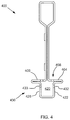
- FIG. 4 is a schematic cross-sectional side view of a vented support beam in accordance with another embodiment of the disclosure.
- FIG. 5 is a schematic cross-sectional side view of a vented support beam in accordance with another embodiment of the disclosure.
- FIG. 6 is a schematic cross-sectional side view of a suspension ceiling ventilation system in accordance with an embodiment of the disclosure.
- FIG. 7 is a detailed view of a single support beam and neighboring ceiling tiles of the suspension ceiling ventilation system of FIG. 6 ;
- FIG. 8 is a detailed view of a single support beam and neighboring ceiling tiles of a suspension ceiling ventilation system according to another embodiment of the disclosure.
- FIG. 9 is a detailed view of a single support beam and neighboring ceiling tiles of a suspension ceiling ventilation system according to yet another embodiment of the disclosure.
- FIG. 10 is a schematic cross-sectional side view of a suspension ceiling ventilation system in accordance with an embodiment of the disclosure.
- FIG. 11 is a schematic cross-sectional side view of a suspension ceiling ventilation system in accordance with an embodiment of the disclosure.
- FIG. 12 is a schematic top view of a suspension ceiling in accordance with another embodiment of the disclosure.
- FIG. 13 illustrates the air flow through a vented support beam in accordance with an embodiment of the disclosure in an example ceiling construction.
- the present inventors have noted that conventional ventilation systems interrupt the pattern and visual of the ceiling surface.
- the present inventors have developed a suspension ceiling support beam and ventilation system that avoids the need to interrupt the ceiling surface and avoids the need for complicated installation methods.
- one aspect of the disclosure is a vented support beam for a suspension ceiling including an elongate body extending in a longitudinal direction, the body including a vertical web and opposing first and second flanges protruding laterally from the vertical web.
- the vented support beam also including a vent formed through the first flange.
- FIG. 1 Vented support beam 100 includes a vertical web 102 and two flanges 104 , 106 protruding laterally from the web 102 .
- First flange 104 is disposed on one side of web 102 and second flange 106 is disposed on the other.
- a first vent 108 extends through the first flange 104 providing fluid communication between a space above first flange 104 and a space below the flange.
- vented support beam 100 further comprises another vent formed through the second flange.
- vented support beam 100 includes a second vent 110 formed through second flange 106 , like first vent 108 , second vent 110 provides fluid communication between a space above and a space below second flange 106 .
- a width of the beam is in a range from 1 ⁇ 4 inch to 2 inches, e.g., from 3 ⁇ 8 to 11 ⁇ 2 inches, e.g., from 1 ⁇ 2 inch to 1 inch.
- a height of the beam is in a range from 1 inch to 3 inches, e.g., from 11 ⁇ 2 inches to 2 inches.
- Vented support beam 100 has a width of 9/16 of an inch and a height of 13 ⁇ 4 inches. The width of vented support beam 100 is governed by the lateral extent of the first and second flanges 104 , 106 , which form the widest part of vented support beam 100 .
- vented support beam 100 may form the widest part of the support beam.
- the height of vented support beam 100 extends from a bulb 112 disposed at the upper end of the beam and a box profile 130 disposed at the lower end of the vented support beam 100 , both of which are described in more detail below.
- the vent extends at least 6 inches in the longitudinal direction, e.g., at least 12 inches, e.g., at least 20 inches.
- vent 108 in first flange 104 extends from a first end 116 of the vented support beam to a second end 118 .
- the vent spans a smaller portion of the length of the vented support beam.
- several vents are provided in a series along the length of the first flange.
- the vent includes a plurality of holes disposed in a line along the longitudinal direction.
- vent 108 includes a plurality of circular holes 109 disposed in a line that runs along a side of support web 102 .
- the holes may have various other shapes, as will be appreciated by the person of ordinary skill in the art.
- vent refers to a single aperture or several apertures that are in close proximity to one another.
- a vent may be formed along the longitudinal direction by several holes where the distance between two of the holes is no more than twice the length of the opening in the longitudinal direction.
- vent holes separated by more than this distance along the longitudinal direction constitute separate vents.
- vent includes a slot extending along the longitudinal direction.
- a vented support beam including such a vent is shown in FIG. 3 .
- vented support beam 300 Similar to vented support beam 100 , vented support beam 300 includes a support web 302 and first and second flanges 304 , 306 protruding laterally therefrom. Further, two vents 308 are provided in first flange 304 . One vent 308 is disposed at one end of vented support beam 300 and another vent 308 is disposed at the other end. In some embodiments, additional vents are provided along the length of the vented support beam. Vent 308 is formed as a slot that extends in the longitudinal direction. While vents 308 have rounded ends, in other embodiments, the openings forming the vents may have other shapes.
- the vented support beam further comprises a channel disposed adjacent to the first and second flanges, where the channel is in fluid communication with the vent.
- the channel is formed by a first side wall projecting down from an outer edge of the first flange and a second side wall projecting down from an outer edge of the second flange.
- vented support beam 100 includes a channel 120 that is adjacent to and in fluid communication with vent 108 . Accordingly, vent 108 provides fluid access between channel 120 and the space above first flange 104 .
- Channel 120 is formed by the first and second flanges 104 , 106 in combination with first side wall 122 and second side wall 128 .
- First sidewall 122 projects down from an outer edge 124 of first flange 104 and second sidewall 128 similarly projects down from an outer edge 126 of second flange 106 .
- the sidewalls 122 , 128 and flanges 104 , 106 provide an enclosed space that forms channel 120 .
- the channel is enclosed in a box profile disposed below the first and second flanges.
- the box profile includes a slot opposite the first and second flanges, where the slot extends in the longitudinal direction.
- channel 120 is provided in a box profile 130 taking the form of an architectural feature of a bolt slot ceiling grid beam.
- box profile 130 includes a slot 132 positioned at the lower end thereof opposite the first and second flanges 104 , 106 .
- vent 108 through first flange 104 at the top of box profile 130 and the slot 132 at the bottom of box profile 130 allows air to pass through the channel 120 from above the vented support beam 100 to below the beam or vice versa.
- the inclusion of this fluid path through the box profile 130 of vented support beam 100 allows the ventilation system to utilize a fluid path in a concealed location, as explained in more detail below.
- vented support beam 400 shown in FIG. 4 , includes a channel 420 that is disposed within box profile 430 .
- the box profile 430 is in the form of a narrow bulb disposed beneath first and second flanges 404 and 406 .
- channel 420 is in fluid communication with vent 408 passing through first flange 404 .
- fluid access out of box profile 430 is provided by openings 432 , 433 in the sidewalls 422 , 428 of the box profile 430 , rather than a slot at the bottom of the box profile.
- vented support beam 500 is in the form of a T-beam.
- vented support beam 500 shown in FIG. 5 , includes first and second flanges 504 , 506 that protrude laterally from a web 502 .
- Each of the first and second flanges 504 , 506 includes a respective vent 508 , 510 in the form of several rows of holes extending through the flanges.
- the beam has a box profile that includes a first sidewall, a second sidewall, a first lip connected to the first sidewall that borders the slot, and a second lip connected to the second sidewall that borders the slot.
- the box profile 130 of vented support beam 100 includes a includes a first lip 134 extending inward from first sidewall 122 and a second lip 136 extending inward from second sidewall 128 toward first lip 134 .
- Slot 132 is formed between the inner ends of first lip 134 and second lip 136 .
- the vented support beam is formed of a cut and shaped metal sheet.
- the vented support beam is formed from a single metal sheet that is bent and cut into the shape of the beam.
- the term metal sheet, as used herein, is not limited to any particular thickness and may include materials conventionally referred to as metal foil, sheet metal, metal plate or metal strips.
- the vented support beam is formed of steel or aluminum.
- the vented support beam is a polymer beam. In some embodiments the polymer beam is extruded, molded, or a combination thereof.
- vented support beam 100 includes a double-walled web 102 including a first support wall 140 and a second support wall 142 .
- the two support walls 140 , 142 are formed from a single metal sheet that is folded back on itself to form the double-walled web.
- first and second support walls 140 , 142 are immediately adjacent such that the neighboring surfaces of the support walls abut one another.
- the support walls are stitched to one another. For example, along the length of web 102 indentations 144 are made that deform both support walls 140 , 142 forming a connection between the walls and strengthening the web 102 .
- the vented support beam further includes a bulb attached to an upper end of the web, and the first and second flanges are disposed at a lower end of the web.
- the metal sheet that forms the two support walls 140 , 142 is looped at the top of vented support beam 100 in the form of a bulb 112 .
- the widened bulb strengthens the beam and improves bending resistance.
- the metal sheet is bent outward to form the opposing webs 104 , 106 .
- the metal sheet continues around the box profile 130 and ends with respective hems at the inner ends of lips 134 , 136 .
- the vented support beam includes a clip for attaching the beam to neighboring components of a ceiling grid.
- each of the first and second ends 116 , 118 of vented support beam 100 includes a clip 144 configured to attach vented support beam 100 to a receiving space in the center of another beam or to the end of another beam.
- clip 144 can be attached to a similar clip extending in the same direction as vented support beam 100 , both of which are held in a receiving space in the middle of a third beam.
- the disclosure provides a suspension ceiling ventilation system including a plurality of support beams arranged in a ceiling grid so as to form a plurality of grid openings in the ceiling grid.
- Each of the support beams includes a vertical web and opposing flanges protruding laterally from the vertical web. At least a portion of the plurality of support beams are vented support beams according to any of the embodiments set forth above.
- the system further comprises a plurality of ceiling tiles, where each of the ceiling tiles is disposed in a respective grid opening of the ceiling grid so as to form a suspension ceiling.
- the suspension ceiling provides a plenum space above the ceiling and an underlying space below the ceiling. A portion of such a suspension ceiling ventilation system is schematically depicted in FIG. 6 .
- System 650 includes a plurality of support beams 652 that are arranged in a ceiling grid 654 in a manner that forms a plurality of openings 656 .
- FIG. 6 is a cross section where only three of the support beams 652 are visible. However, ceiling grid 654 includes further support beams that run perpendicular to support beams 652 .
- Each of the support beams 652 in ceiling grid 654 has a similar configuration to that of vented support beam 100 and includes a double-walled vertical web, opposing flanges that protrude laterally from the web and establish a box profile at the lower end of the web, and a bulb at the upper end of the web.
- a portion of the support beams 652 in ceiling grid 654 are vented support beams 600 that are identical to vented support beam 100 .
- the remaining support beams 652 are similar to the vented support beam 600 , differing only in that they do not include a vent.
- FIG. 6 shows two vented support beams 600 and one non-vented support beam 658 .
- System 650 further includes a plurality of ceiling tiles 660 disposed in the grid openings 656 formed in ceiling grid 654 .
- the combination of the ceiling tiles 660 and ceiling grid 654 forms a suspension ceiling 670 that provides a plenum space 672 above the suspension ceiling and an underlying space 674 below the ceiling.
- Each of the grid openings has a width and a breadth for holding a respective ceiling tile.
- the term grid opening refers to the standardized openings in the middle of the grid, and not to the openings at the perimeter of the grid, which may be sized differently, and are described further below.
- each of the grid openings has a width is in a range of 20 to 30 inches, e.g., 23 to 25 inches.
- each grid opening has a breadth in a range of 20 to 60 inches, e.g., a breadth in a range of 20 to 30 inches, e.g., 23 to 25 inches.
- each of the flanges of the support beams includes a contact area
- the ceiling tiles are supported by the respective contact areas of the support beams.
- at least a portion of the flanges of support beams 652 provide a contact area disposed on a surface on an upper side of the flange for contacting a ceiling tile 660 that is placed in the neighboring grid opening 656 .
- the ceiling grid 654 provides support for ceiling tiles 660 that are placed in grid openings 656 .
- the contact area of the first flange of the vented support beam includes an outside portion of the first flange, and the vent through the first flange extends through an inside portion of the first flange.
- vented support beam 600 as shown in the detailed view of FIG. 7 , includes contact area 659 on an outside portion of first flange 604 , while vent 608 is formed through the inside portion of first flange 604 . Accordingly, when ceiling tile 660 is placed on contact area 659 , vent 608 is unobstructed and air can flow therethrough.
- outside portion refers to a portion that is at the lateral outer side of the support beam, i.e., a portion that is away from the horizontal center of the support beam.
- inside portion is a portion that is nearer the horizontal center of the support beam.
- each of the ceiling tiles includes a central body and a projection extending from an edge of the central body.
- Each of the projections is supported by a respective flange of an adjacent support beam.
- ceiling tile 660 includes a central body 662 and a projection 664 extending outward from an outer edge of the central body.
- the projection 664 allows ceiling tile 660 to be supported on first flange 604 while the lower end of vented support beam 600 and the lower surface of ceiling tile 660 are flush.
- the flush positioning of the support beam 600 and ceiling tile 660 provides an attractive continuous lower surface of the suspension ceiling 670 .
- the lower surface of the ceiling tile is flat, and the body of the ceiling tile is supported directly by the flange.
- each of at least a portion of the ceiling tiles includes a notch that forms an opening in the respective ceiling tile to provide fluid access to the vent of a respective vented support beam.
- portions of the projection 864 of ceiling tile 860 extend over the entire width of flange 804 .
- the ceiling tile, particularly the projection of the ceiling tile includes a notch 866 positioned over the hole forming vent 808 . Accordingly, air can flow through notch 866 to reach vent 808 .
- the ceiling tiles include a gasket disposed at an outer edge thereof, wherein the gasket contacts a respective flange of at least one of the support beams.
- the ceiling tiles 960 each include a gasket 968 disposed between the projection 964 of ceiling tile 960 and the flange 904 of the vented support beam 900 .
- the gasket forms a seal between the ceiling tile and the support beam, which forces air through the vent instead of through any gap between the ceiling tile and the adjacent flange.
- the use of the gasket allows the ceiling tile to be set back from the vent, which can improve air flow through the vent.
- the plenum space has a first pressure and the underlying space has a second pressure that is different from the first pressure so as to force air through the respective vents of the vented support beams.
- the suspension ceiling ventilation system further includes a duct providing fluid communication between the plenum space and a compressor.
- ventilation system 650 includes a duct 676 that extends into plenum space 672 .
- Duct 676 is downstream of a compressor that forces air into plenum space 672 creating an elevated pressure therein. The elevated pressure in plenum space 672 forces air through the vented support beams 600 and into underlying space 674 .
- the duct is upstream of the compressor, which drives air out of the plenum space.
- duct 1076 is connected to plenum space 1072 and is located upstream of a compressor that removes air from plenum space 1072 .
- the compressor therefore creates a pressure drop in plenum space 1072 so that air flows from the underlying space 1074 through the vented support beams 1000 of suspension ceiling 1070 and into the plenum space 1072 .
- the suspension ceiling ventilation system includes a divider that separates a first section of the plenum space from a second section of the plenum space.
- the first section of the plenum space has a first pressure
- the second section of the plenum space has a second pressure
- the underlying space has a third pressure that is between the first and second pressures so as to force air from the first section of the plenum space to the underlying space through respective vents of a first group of the vented support beams and to force air from the underlying space to the second section of the plenum space through respective vents of a second group of the vented support beams.
- ventilation system 1150 shown in FIG.
- a divider 1175 within the plenum space 1172 that divides the plenum space into a first section 1178 and a second section 1179 .
- a first duct 1176 extends into the first section 1178 of the plenum space 1172
- a second duct 1177 extends into the second section 1179 of the plenum space 1172 .
- One or more compressors in fluid communication with the air ducts 1176 , 1177 causes a pressure differential between the first section 1178 and second section 1179 .
- the pressure differential between the two sections 1178 , 1179 of the plenum space causes air to flow into the underlying space 1174 through the vented support beams 1100 that are adjacent to the first section of the plenum space.
- the pressure differential further causes the air to flow from the underlying space 1174 into the second section 1179 of the plenum space through the associated vented support beams.
- the vented support beams 1100 of the suspension ceiling 1170 provide both the air supply and return for the underlying space 1174 .
- the divider 1175 in ventilation system 1150 is attached to a support beam of the suspension ceiling.
- the divider may be integrally formed with one of the support beams.
- the divider may divide the plenum space in other ways as will be appreciated by those of ordinary skill in the art.
- a first portion of the support beams extend in a first direction and a second portion of the support beams extend in a second direction, where the first direction is at an angle to the second direction.
- ceiling 1270 shown in FIG. 12 includes a ceiling grid 1254 with a plurality of support beams running perpendicular to one another. A first portion of the support beams run along the length of the ceiling 1270 and a second portion run across the width of the ceiling.
- the first portion of support beams includes main runners that span a plurality of the grid openings of the ceiling grid
- the second portion of support beams includes cross beams that extend from a respective one of the main runners to a neighboring main runner.
- ceiling grid 1254 includes main runners 1280 that run along the entire length of ceiling 1270 and span six grid openings 1256 and the corresponding ceiling tiles 1260 . While the main runners in ceiling 1270 span the entire length of the ceiling, in other embodiments, the main runners extend across multiple openings but span only a fraction of the ceiling.
- Cross beams 1282 extend between neighboring pairs of main runners 1280 . Together, a group of cross beams 1282 spans the width of ceiling 1270 . In other embodiments, the main runners extend across the width of the ceiling while the cross beams extend across the length.
- a first portion of the cross beams are vented support beams and a second portion of the cross beams are unvented support beams.
- a first portion of the cross beams are vented support beams and a second portion of the cross beams are unvented support beams.
- ceiling 1270 there are four rows of cross beams 1282 . Two of the rows are entirely formed with cross beams 1282 taking the form of vented support beams 1200 . The other two rows include both cross beams 1282 in the form of vented support beams 1200 and unvented support beams 1258 .
- the fraction of the ceiling grid that is formed by vented support beams impacts the flow of air between the plenum space and the underlying space.
- cross beams 1282 Because of the large number of cross beams 1282 , the using cross beams that are both vented and unvented allows a builder to select a precise percentage of the grid that is formed with vented support beams, which allows fine tuning of the flow rate between the plenum space and underlying space. While the main runners 1280 in ceiling 1270 are unvented, in other embodiments, the main runners are vented. Still in other embodiments a portion of the main runners are vented and a portion are unvented.
- the grid forms edge openings along at least one perimeter edge of the suspension ceiling
- the suspension ceiling ventilation system further comprises ceiling tile sections disposed in the edge openings.
- the openings 1284 around the perimeter of ceiling 1270 are smaller than the grid openings 1256 in the center of the ceiling.
- a section of ceiling tile 1286 is positioned in each of the edge openings 1284 .
- the ceiling includes features that interrupt the ceiling tiles of the suspension ceiling.
- the ceiling includes lighting fixtures and emergency components, such as sprinklers.
- the ceiling includes one or more diffusers that cooperate with the vented ceiling grid.
- the disclosure provides a method of constructing a suspension ceiling ventilation system according to any of the embodiments described above.
- the method includes arranging a plurality of support beams in a ceiling grid that is coupled to a support structure, where the ceiling grid includes a plurality of grid openings between the support beams.
- Each of the support beams includes a vertical web and opposing flanges protruding laterally from the vertical web, wherein at least a portion of the plurality of support beams are vented support beams.
- the method further includes positioning each of a plurality of ceiling tiles in a respective grid opening of the ceiling grid so as to form a suspension ceiling, where the suspension ceiling provides a plenum space above the ceiling and an underlying space below the ceiling.
- ceiling 1270 of FIG. 12 includes a ceiling grid 1254 that is coupled by brackets 1290 to a wall 1292 disposed around the perimeter of ceiling 1270 .
- each of the beams at the outer perimeter of ceiling grid 1254 is attached to a respective bracket 1290 using mechanical fasteners which are, in turn, attached to the wall 1292 .
- the ceiling grid 1254 once assembled, forms a plurality of grid openings 1256 and edge openings 1284 .
- ceiling tiles 1260 are inserted into the grid openings 1256 and ceiling tile sections are inserted into the edge openings 1284 .
- At least a portion of the support beams take the form of vented support beams 1200 .
- the method further includes providing a notch at an outer edge of at least one of the plurality of ceiling tiles so as to form an opening in the respective ceiling tile to provide fluid access to the vent of a respective vented support beam.
- a notch such as notch 866 shown in suspension ceiling ventilation system 850 , is added to the ceiling tile at installation.
- the builder removes the notch before placing the ceiling tile on the flange of a respective beam.
- an area corresponding to the notch is perforated to allow for easy removal of the notch during installation.
- the notch is formed at the manufacturing cite.
- the method further includes coupling a duct to the plenum space, where the duct is in fluid communication with a compressor, and operating the compressor so as to provide a pressure differential between the plenum space and the underlying space so as to force air through the respective vents of the vented support beams.
- a compressor is in fluid communication with duct 676 and is operated to force air into plenum space 672 . This forced air then creates an increase in pressure, which forces air through the vented support beams 600 into underlying space 674 .
- a first portion of the support beams extend in a first direction and a second portion of the support beams extend in a second direction, and wherein the first direction is at an angle to the second direction.
- the main runners 1280 of the ceiling grid 1254 are arranged to extend in the length direction.
- the cross beams 1282 are arranged to extend in the width direction, at 90 degrees from the main runners 1280 .
- the method further includes selecting the number of vented support beams in the ceiling grid based on a desired air flow rate between the plenum space and the underlying space. For example, as explained above, in certain embodiments, a portion of the ceiling grid is formed by vented support beams and a portion is formed by unvented support beams. Due to the extent of beams in the grid, the builder can choose the ratio of the grid that is formed by vented support beams in order to control the flow rate between the plenum space and the underlying space.
- FIG. 13 illustrates the air flow through a vented support beam in accordance with an embodiment of the disclosure in an example ceiling construction.
- the example includes a room having 8′ high ceilings with a ceiling area of 28′ ⁇ 16′.
- the room is configured to have five air changes per hour, which corresponds to an air flow of 300 CFM.
- the ceiling grid is formed of 672 feet of vented support beams including rows of circular holes having a diameter of 0.050′′ and spaced at 0.100′′ center-to-center, providing a total of 153,216 holes in the vented grid. Based on the total air flow and the number of holes, the air flow per hole was determined to be 0.00195 CFM, with an average air speed of 0.73 m/s.
- Minor head loss is expressed as multiples of the velocity head, where K is the loss coefficient, and minor head loss can be used to solve for velocity as shown in equation (1).
- the pressure drop needed to achieve the volume flow rate of 300 CFM in the example ceiling construction is 0.87 Pa, or 0.00013 psi.
- Finite element calculations agreed with the foregoing calculation based on the handbook value of Cd.
- the above is but a single example, and that the size and number of the holes and perforations can be varied to fit the air volumes and air speeds required for a wide variety of spaces, all of which would be derivable from the provided equations.
- the required volumes of air exchanged may be increased above such minimums and targets for a variety of reasons, including occupant comfort or efficiency of compressor or system operation.
- a vented support beam for a suspension ceiling comprising:
- a width of the beam is in a range from 1 ⁇ 4 inch to 2 inches, e.g., from 3 ⁇ 8 to 11 ⁇ 2 inches, e.g., from 1 ⁇ 2 inch to 1 inch.
- a height of the beam is in a range from 1 inch to 3 inches, e.g., from 11 ⁇ 2 inches to 2 inches.
- vent extends at least 6 inches in the longitudinal direction, e.g., at least 12 inches, e.g., at least 20 inches.
- vent includes a plurality of holes disposed in a line along the longitudinal direction.
- vent includes a slot extending along the longitudinal direction.
- vented support beam according to any of embodiments 1 to 7, further comprising a channel disposed adjacent to the first and second flanges,
- the box profile includes a slot opposite the first and second flanges, wherein the slot extends in the longitudinal direction.
- the box profile includes a first sidewall, a second sidewall, a first lip connected to the first sidewall that borders the slot, and a second lip connected to the second sidewall that borders the slot.
- vented support beam according to any of embodiments 1 to 14, further comprising a bulb attached to an upper end of the web, and
- a suspension ceiling ventilation system comprising:
- each of the flanges of the support beams includes a contact area
- each of the ceiling tiles includes a central body and a projection extending from an edge of the central body
- each of at least a portion of the ceiling tiles include a notch that forms an opening in the respective ceiling tile to provide fluid access to the vent of a respective vented support beam.
- each of at least a portion of the ceiling tiles include a gasket disposed at an outer edge thereof, wherein the gasket contacts a respective flange of at least one of the support beams.
- suspension ceiling ventilation system according to any of embodiments 16 to 21, wherein the plenum space has a first pressure and the underlying space has a second pressure that is different from the first pressure so as to force air through the respective vents of the vented support beams.
- suspension ceiling ventilation system according to any of embodiments 16 to 21, further comprising a divider that separates a first section of the plenum space from a second section of the plenum space,
- the method according to embodiment 29, further comprising providing a notch at an outer edge of at least one of the plurality of ceiling tiles so as to form an opening in the respective ceiling tile to provide fluid access to the vent of a respective vented support beam.
Landscapes
- Engineering & Computer Science (AREA)
- Architecture (AREA)
- Physics & Mathematics (AREA)
- Electromagnetism (AREA)
- Civil Engineering (AREA)
- Structural Engineering (AREA)
- Duct Arrangements (AREA)
- Building Environments (AREA)
Priority Applications (1)
| Application Number | Priority Date | Filing Date | Title |
|---|---|---|---|
| US16/368,234 US10858829B2 (en) | 2018-03-31 | 2019-03-28 | Vented suspension ceiling beam and suspension ceiling system |
Applications Claiming Priority (2)
| Application Number | Priority Date | Filing Date | Title |
|---|---|---|---|
| US201862651092P | 2018-03-31 | 2018-03-31 | |
| US16/368,234 US10858829B2 (en) | 2018-03-31 | 2019-03-28 | Vented suspension ceiling beam and suspension ceiling system |
Publications (2)
| Publication Number | Publication Date |
|---|---|
| US20190323233A1 US20190323233A1 (en) | 2019-10-24 |
| US10858829B2 true US10858829B2 (en) | 2020-12-08 |
Family
ID=68060415
Family Applications (1)
| Application Number | Title | Priority Date | Filing Date |
|---|---|---|---|
| US16/368,234 Active US10858829B2 (en) | 2018-03-31 | 2019-03-28 | Vented suspension ceiling beam and suspension ceiling system |
Country Status (4)
| Country | Link |
|---|---|
| US (1) | US10858829B2 (de) |
| EP (1) | EP3775427B1 (de) |
| CA (1) | CA3095900A1 (de) |
| WO (1) | WO2019191477A1 (de) |
Cited By (2)
| Publication number | Priority date | Publication date | Assignee | Title |
|---|---|---|---|---|
| US20230111321A1 (en) * | 2020-03-13 | 2023-04-13 | Saint-Gobain Ecophon Ab | Ceiling tile and suspended ceiling system comprising such a ceiling tile |
| USD1019989S1 (en) * | 2016-11-14 | 2024-03-26 | Certainteed Ceilings Corporation | Support member for ceiling system |
Families Citing this family (8)
| Publication number | Priority date | Publication date | Assignee | Title |
|---|---|---|---|---|
| US10267038B2 (en) * | 2015-09-03 | 2019-04-23 | Awi Licensing Llc | Ceiling system |
| USD829345S1 (en) * | 2016-11-14 | 2018-09-25 | Certainteed Ceilings Corporation | Support member for ceiling system |
| US20200173171A1 (en) * | 2018-11-30 | 2020-06-04 | Worthington Armstrong Venture | Low profile suspended ceiling beam |
| USD1047225S1 (en) * | 2021-11-23 | 2024-10-15 | Rockwool A/S | Support member for a suspended ceiling |
| EP4246049A1 (de) * | 2022-03-14 | 2023-09-20 | Saint-Gobain Ecophon AB | Diffusions-deckenlüftungssystem |
| CN116293928B (zh) * | 2023-04-04 | 2026-02-13 | 箭牌家居集团股份有限公司 | 空气处理系统 |
| CN116607691B (zh) * | 2023-06-27 | 2025-07-11 | 浙江亚厦装饰股份有限公司 | 一种装配式吊顶风口安装结构及安装方法 |
| CN117966959B (zh) * | 2024-03-28 | 2024-06-21 | 中国建筑一局(集团)有限公司 | 可折叠且可升降的模块化金属网吊顶施工结构及施工方法 |
Citations (20)
| Publication number | Priority date | Publication date | Assignee | Title |
|---|---|---|---|---|
| US2859681A (en) * | 1956-03-28 | 1958-11-11 | Joel R Rachlin | Air-flow ceiling arrangements |
| US3101661A (en) | 1961-07-18 | 1963-08-27 | Lok Products Co | T-runner |
| US3252399A (en) * | 1964-01-13 | 1966-05-24 | Wood Conversion Co | Ventilating ceiling and panel therefor |
| US3444800A (en) * | 1962-08-16 | 1969-05-20 | United States Gypsum Co | Ventilating partition construction |
| US3475869A (en) * | 1966-09-07 | 1969-11-04 | Chicago Metallic Sash Co | Ventilated suspended ceiling structure |
| US3584565A (en) | 1969-04-10 | 1971-06-15 | Bundy Corp | Air vent ceiling grid member |
| US3601033A (en) * | 1969-09-04 | 1971-08-24 | Air Factors | Air diffuser assembly with integral air return |
| US3848385A (en) | 1970-06-12 | 1974-11-19 | Nat Ceiling Corp | Modular ceiling construction |
| US4535580A (en) * | 1981-07-09 | 1985-08-20 | Donn Incorporated | Screw slot runner system |
| US4542615A (en) * | 1982-03-30 | 1985-09-24 | Specified Ceiling Systems | Drop ceiling framework |
| US4712350A (en) * | 1986-05-16 | 1987-12-15 | Chicago Metallic Corporation | Centering arrangement for T members of a suspended ceiling |
| KR910002420Y1 (ko) | 1988-06-18 | 1991-04-20 | 주식회사 유 창 | 천정판 주간받이의 통기장치 |
| US6405543B2 (en) * | 1997-05-16 | 2002-06-18 | Work Smart Energy Enterprises Inc. | High-efficiency air-conditioning system with high-volume air distribution |
| US20030213853A1 (en) * | 2002-05-17 | 2003-11-20 | Demster Stanley J. | Method and apparatus for delivering conditioned air using dual plenums |
| US7712274B2 (en) * | 2006-12-29 | 2010-05-11 | Usg Interiors, Inc. | Downwardly accessible lift-and-shift ceiling system |
| EP2378023A1 (de) | 2010-04-14 | 2011-10-19 | Nederlandse Organisatie voor toegepast -natuurwetenschappelijk onderzoek TNO | Deckensystem mit Rahmenwerk und Platten und mit Mitteln zur Erzeugung von Belüftungslücken |
| US9328510B1 (en) * | 2015-07-07 | 2016-05-03 | Awi Licensing Company | Ceiling system |
| WO2018053136A1 (en) | 2016-09-15 | 2018-03-22 | Armstrong World Industries, Inc. | Ceiling system with air movement |
| US20180135300A1 (en) * | 2016-11-14 | 2018-05-17 | Certainteed Ceilings Corporation | Support Member For Ceiling System |
| US20190186133A1 (en) * | 2016-08-24 | 2019-06-20 | Jean-Marc Scherrer | Hanger profile allowing for the passage of air and ceiling assembly comprising such a profile |
-
2019
- 2019-03-28 EP EP19776566.2A patent/EP3775427B1/de active Active
- 2019-03-28 US US16/368,234 patent/US10858829B2/en active Active
- 2019-03-28 CA CA3095900A patent/CA3095900A1/en active Pending
- 2019-03-28 WO PCT/US2019/024656 patent/WO2019191477A1/en not_active Ceased
Patent Citations (20)
| Publication number | Priority date | Publication date | Assignee | Title |
|---|---|---|---|---|
| US2859681A (en) * | 1956-03-28 | 1958-11-11 | Joel R Rachlin | Air-flow ceiling arrangements |
| US3101661A (en) | 1961-07-18 | 1963-08-27 | Lok Products Co | T-runner |
| US3444800A (en) * | 1962-08-16 | 1969-05-20 | United States Gypsum Co | Ventilating partition construction |
| US3252399A (en) * | 1964-01-13 | 1966-05-24 | Wood Conversion Co | Ventilating ceiling and panel therefor |
| US3475869A (en) * | 1966-09-07 | 1969-11-04 | Chicago Metallic Sash Co | Ventilated suspended ceiling structure |
| US3584565A (en) | 1969-04-10 | 1971-06-15 | Bundy Corp | Air vent ceiling grid member |
| US3601033A (en) * | 1969-09-04 | 1971-08-24 | Air Factors | Air diffuser assembly with integral air return |
| US3848385A (en) | 1970-06-12 | 1974-11-19 | Nat Ceiling Corp | Modular ceiling construction |
| US4535580A (en) * | 1981-07-09 | 1985-08-20 | Donn Incorporated | Screw slot runner system |
| US4542615A (en) * | 1982-03-30 | 1985-09-24 | Specified Ceiling Systems | Drop ceiling framework |
| US4712350A (en) * | 1986-05-16 | 1987-12-15 | Chicago Metallic Corporation | Centering arrangement for T members of a suspended ceiling |
| KR910002420Y1 (ko) | 1988-06-18 | 1991-04-20 | 주식회사 유 창 | 천정판 주간받이의 통기장치 |
| US6405543B2 (en) * | 1997-05-16 | 2002-06-18 | Work Smart Energy Enterprises Inc. | High-efficiency air-conditioning system with high-volume air distribution |
| US20030213853A1 (en) * | 2002-05-17 | 2003-11-20 | Demster Stanley J. | Method and apparatus for delivering conditioned air using dual plenums |
| US7712274B2 (en) * | 2006-12-29 | 2010-05-11 | Usg Interiors, Inc. | Downwardly accessible lift-and-shift ceiling system |
| EP2378023A1 (de) | 2010-04-14 | 2011-10-19 | Nederlandse Organisatie voor toegepast -natuurwetenschappelijk onderzoek TNO | Deckensystem mit Rahmenwerk und Platten und mit Mitteln zur Erzeugung von Belüftungslücken |
| US9328510B1 (en) * | 2015-07-07 | 2016-05-03 | Awi Licensing Company | Ceiling system |
| US20190186133A1 (en) * | 2016-08-24 | 2019-06-20 | Jean-Marc Scherrer | Hanger profile allowing for the passage of air and ceiling assembly comprising such a profile |
| WO2018053136A1 (en) | 2016-09-15 | 2018-03-22 | Armstrong World Industries, Inc. | Ceiling system with air movement |
| US20180135300A1 (en) * | 2016-11-14 | 2018-05-17 | Certainteed Ceilings Corporation | Support Member For Ceiling System |
Non-Patent Citations (1)
| Title |
|---|
| International Search Report and Written Opinion in International Patent Application PCT/US2019/024656 dated Aug. 5, 2019. |
Cited By (2)
| Publication number | Priority date | Publication date | Assignee | Title |
|---|---|---|---|---|
| USD1019989S1 (en) * | 2016-11-14 | 2024-03-26 | Certainteed Ceilings Corporation | Support member for ceiling system |
| US20230111321A1 (en) * | 2020-03-13 | 2023-04-13 | Saint-Gobain Ecophon Ab | Ceiling tile and suspended ceiling system comprising such a ceiling tile |
Also Published As
| Publication number | Publication date |
|---|---|
| EP3775427C0 (de) | 2024-10-09 |
| EP3775427A1 (de) | 2021-02-17 |
| EP3775427B1 (de) | 2024-10-09 |
| WO2019191477A1 (en) | 2019-10-03 |
| US20190323233A1 (en) | 2019-10-24 |
| EP3775427A4 (de) | 2021-12-22 |
| CA3095900A1 (en) | 2019-10-03 |
Similar Documents
| Publication | Publication Date | Title |
|---|---|---|
| US10858829B2 (en) | Vented suspension ceiling beam and suspension ceiling system | |
| KR100773846B1 (ko) | 모듈라 서비스 유닛 | |
| US3207057A (en) | Panel supporting grid | |
| US5144781A (en) | Double floor for removing air from rooms | |
| CN1759279A (zh) | 诱导型扩散器 | |
| US2859681A (en) | Air-flow ceiling arrangements | |
| US2099211A (en) | Building construction and panel for use therein | |
| US4060025A (en) | Air distribution ceiling | |
| US3411425A (en) | Air diffusion outlet with laterally adjustable weir control | |
| WO2006083759A1 (en) | Adaptable ceiling tile system | |
| EP2542730B1 (de) | Deckensystem mit Rahmenwerk und Platten und mit Mitteln zur Erzeugung von Belüftungslücken | |
| MX2011000966A (es) | Salida de aire de techo para instalaciones tecnicas de aire acondicionado. | |
| US3440947A (en) | Combination diffuser and false ceiling suspension systems | |
| US3636340A (en) | Air-handling ceiling channel structure | |
| US3132579A (en) | Ceiling duct structure | |
| KR102060192B1 (ko) | 확장부가 갖추어진 바람통로를 가지는 통풍형 방음패널 및 이를 이용한 방음벽 | |
| KR101541238B1 (ko) | 침입수 차단 및 통풍 성능을 향상시킨 에어 벤트 커버 구조물 | |
| JP3213600B2 (ja) | 天井パネルの落下防止ハンガー | |
| JP3213598B2 (ja) | 天井パネルの目地スペーサー | |
| EP2378023A1 (de) | Deckensystem mit Rahmenwerk und Platten und mit Mitteln zur Erzeugung von Belüftungslücken | |
| CN201724351U (zh) | 不漏光的回风口架及其导流板 | |
| US3590719A (en) | Polygonal tile, suspended ceiling integrated acoustiplaque air diffuser assembly | |
| JP2008095353A (ja) | 天井構造及びその構築方法 | |
| PH12016000389A1 (en) | Louver | |
| JP2006145117A (ja) | 空調用吹出口 |
Legal Events
| Date | Code | Title | Description |
|---|---|---|---|
| FEPP | Fee payment procedure |
Free format text: ENTITY STATUS SET TO UNDISCOUNTED (ORIGINAL EVENT CODE: BIG.); ENTITY STATUS OF PATENT OWNER: LARGE ENTITY |
|
| STPP | Information on status: patent application and granting procedure in general |
Free format text: DOCKETED NEW CASE - READY FOR EXAMINATION |
|
| STPP | Information on status: patent application and granting procedure in general |
Free format text: NON FINAL ACTION MAILED |
|
| STPP | Information on status: patent application and granting procedure in general |
Free format text: NON FINAL ACTION MAILED |
|
| AS | Assignment |
Owner name: CERTAINTEED CEILINGS CORPORATION, PENNSYLVANIA Free format text: NUNC PRO TUNC ASSIGNMENT;ASSIGNORS:RAPPOSELLI, MATTHEW;CZYZEWICZ, ROBIN C.;RANDLETT, ISABELLE ETCHART;AND OTHERS;SIGNING DATES FROM 20201006 TO 20201015;REEL/FRAME:054285/0579 |
|
| STCF | Information on status: patent grant |
Free format text: PATENTED CASE |
|
| MAFP | Maintenance fee payment |
Free format text: PAYMENT OF MAINTENANCE FEE, 4TH YEAR, LARGE ENTITY (ORIGINAL EVENT CODE: M1551); ENTITY STATUS OF PATENT OWNER: LARGE ENTITY Year of fee payment: 4 |