EP2378023A1 - Deckensystem mit Rahmenwerk und Platten und mit Mitteln zur Erzeugung von Belüftungslücken - Google Patents
Deckensystem mit Rahmenwerk und Platten und mit Mitteln zur Erzeugung von Belüftungslücken Download PDFInfo
- Publication number
- EP2378023A1 EP2378023A1 EP10159902A EP10159902A EP2378023A1 EP 2378023 A1 EP2378023 A1 EP 2378023A1 EP 10159902 A EP10159902 A EP 10159902A EP 10159902 A EP10159902 A EP 10159902A EP 2378023 A1 EP2378023 A1 EP 2378023A1
- Authority
- EP
- European Patent Office
- Prior art keywords
- ceiling
- panels
- panel
- spacing means
- support profiles
- Prior art date
- Legal status (The legal status is an assumption and is not a legal conclusion. Google has not performed a legal analysis and makes no representation as to the accuracy of the status listed.)
- Ceased
Links
Images


Classifications
-
- E—FIXED CONSTRUCTIONS
- E04—BUILDING
- E04B—GENERAL BUILDING CONSTRUCTIONS; WALLS, e.g. PARTITIONS; ROOFS; FLOORS; CEILINGS; INSULATION OR OTHER PROTECTION OF BUILDINGS
- E04B9/00—Ceilings; Construction of ceilings, e.g. false ceilings; Ceiling construction with regard to insulation
- E04B9/02—Ceilings; Construction of ceilings, e.g. false ceilings; Ceiling construction with regard to insulation having means for ventilation or vapour discharge
-
- E—FIXED CONSTRUCTIONS
- E04—BUILDING
- E04B—GENERAL BUILDING CONSTRUCTIONS; WALLS, e.g. PARTITIONS; ROOFS; FLOORS; CEILINGS; INSULATION OR OTHER PROTECTION OF BUILDINGS
- E04B9/00—Ceilings; Construction of ceilings, e.g. false ceilings; Ceiling construction with regard to insulation
- E04B9/06—Ceilings; Construction of ceilings, e.g. false ceilings; Ceiling construction with regard to insulation characterised by constructional features of the supporting construction, e.g. cross section or material of framework members
- E04B9/064—Ceilings; Construction of ceilings, e.g. false ceilings; Ceiling construction with regard to insulation characterised by constructional features of the supporting construction, e.g. cross section or material of framework members comprising extruded supporting beams
-
- E—FIXED CONSTRUCTIONS
- E04—BUILDING
- E04B—GENERAL BUILDING CONSTRUCTIONS; WALLS, e.g. PARTITIONS; ROOFS; FLOORS; CEILINGS; INSULATION OR OTHER PROTECTION OF BUILDINGS
- E04B9/00—Ceilings; Construction of ceilings, e.g. false ceilings; Ceiling construction with regard to insulation
- E04B9/06—Ceilings; Construction of ceilings, e.g. false ceilings; Ceiling construction with regard to insulation characterised by constructional features of the supporting construction, e.g. cross section or material of framework members
- E04B9/065—Ceilings; Construction of ceilings, e.g. false ceilings; Ceiling construction with regard to insulation characterised by constructional features of the supporting construction, e.g. cross section or material of framework members comprising supporting beams having a folded cross-section
- E04B9/067—Ceilings; Construction of ceilings, e.g. false ceilings; Ceiling construction with regard to insulation characterised by constructional features of the supporting construction, e.g. cross section or material of framework members comprising supporting beams having a folded cross-section with inverted T-shaped cross-section
- E04B9/068—Ceilings; Construction of ceilings, e.g. false ceilings; Ceiling construction with regard to insulation characterised by constructional features of the supporting construction, e.g. cross section or material of framework members comprising supporting beams having a folded cross-section with inverted T-shaped cross-section with double web
-
- E—FIXED CONSTRUCTIONS
- E04—BUILDING
- E04B—GENERAL BUILDING CONSTRUCTIONS; WALLS, e.g. PARTITIONS; ROOFS; FLOORS; CEILINGS; INSULATION OR OTHER PROTECTION OF BUILDINGS
- E04B9/00—Ceilings; Construction of ceilings, e.g. false ceilings; Ceiling construction with regard to insulation
- E04B9/02—Ceilings; Construction of ceilings, e.g. false ceilings; Ceiling construction with regard to insulation having means for ventilation or vapour discharge
- E04B2009/026—Ceilings; Construction of ceilings, e.g. false ceilings; Ceiling construction with regard to insulation having means for ventilation or vapour discharge the supporting ceiling grid acting as air diffusers
Definitions
- the present invention refers to a ceiling system comprising a plurality of ceiling panels and a ceiling framework for supporting those panels.
- the invention refers to a so-called dropped ceiling system, i.e. a lowered (secondary) ceiling, hung below mainly parallel to the main (structural) ceiling. They may also be referred to as a drop ceiling, false ceiling, or suspended ceiling.
- the area above the dropped ceiling is called the plenum space, as it is sometimes used for HVAC air return.
- the plenum space is also very commonly used to conceal piping, wiring, and/or ductwork.
- a typical dropped ceiling consists of a grid-work of metal channels in the shape of an upside-down "T", suspended on wires from the overhead structure. These channels snap together in a regularly spaced pattern - typically a 2 ⁇ 2 or 2 ⁇ 4 foot grid in the US, or 600x600 or 600 ⁇ 1200 mm grid in Europe. Each cell is filled with lightweight "tiles” or “panels” which simply drop into the grid. Tiles can be selected with a variety of materials, including wood, metal, plastic, or mineral fibers, and can come in almost any color. Light fixtures, HVAC air grilles, and other fixtures are available which can fit the same space as a tile for easy installation. Most tile material is easily cut to allow fixtures in other shapes, such as incandescent lights, speakers, and fire sprinkler heads.
- An earlier patent application W02009005344 of applicant discloses a ventilation method and system respectively for ventilating rooms like classrooms and the like, comprising a surface structure mainly extending parallel to the ceiling, and means for forced air inlet from the outside air into the room between said surface structure and the ceiling.
- Air outlet openings are provided, which are mainly evenly spaced over the whole surface of the surface structure.
- the hydraulic diameter of the outlet openings is between 0.1 and 6 cm.
- the means for forced air inlet from the outside air into the room (or plenum space) between the surface structure and said wall, ceiling or floor are formed by an electrical ventilator.
- the panels concerned are provided with holes which can be made during the manufacturing process of the panels or -e.g. when already installed panels are used- by drilling. Disadvantageous is that
- One aim of the present invention is to provide a system which e.g. is arranged to perform a method as presented in W02009005344 , however without the obligation to provide -during or after their manufacture- the relevant panels with holes.
- Another aim of the present invention is to provide means by which standard panels can be used.
- a ceiling system comprising a plurality of ceiling panels and a ceiling framework for supporting those panels, said framework including panel support profiles each including a vertical portion and a horizontal portion, wherein
- said spacing means for creating a space forming at least part of a duct allowing air to flow upwards and/or downwards, as well as providing the relevant support profiles with apertures for allowing air to flow into, through or out of said duct, the panels don't need to be provided with ventilation holes. Moreover, standard panels can be used, even if already installed in an existing ceiling system.
- the ceiling system preferably, is arranged to be used in a ventilation system wherein an overpressure is provided at the top side relative to the lower side of the ceiling, causing a ventilation stream to flow from the top side to the lower side of the ceiling via said vertical gaps.
- an overpressure is provided at the top side relative to the lower side of the ceiling, causing a ventilation stream to flow from the top side to the lower side of the ceiling via said vertical gaps.
- the outflow area of the duct is, preferably, shaped to align said ventilation stream into a mainly downward direction.
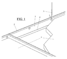
- Figure 1 shows a prior art ceiling system including ceiling panels 1 and a ceiling framework including support profiles 2 with vertical portions 3 and horizontal portions 4.
- the framework is hung below mainly parallel to the main (structural) ceiling by means of hooks 5.
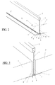
- Figure 2 shows a first embodiment of the ceiling system according to the invention, with one panel omitted and one panel 1 of a visible.
- a ceiling framework for supporting a plurality of ceiling panels includes panel support profiles 2 each including a vertical portion 3 and a horizontal portion 4.
- Spacing means 6 are provided, arranged to create a space 7 between a side edge of each panel 1 and (the surface of) the neighbouring vertical portion 3 of the support profile 2, and thus between opposed side edges of two neighbouring panels (separated by the wall thickness of the vertical portion 3 of the support profile 2).
- the space 7 thus forms a main part of a duct or gap (also indicated with reference sign 7 hereinafter) allowing air to flow upwards and/or downwards.
- the spacing means are incorporated in or integrated with the vertical portions of the panel support profiles and include protrusions 6 for spacing the side edge of each relevant panel 1 to the vertical portion 3 of the support profile 2.
- the protrusions 6, pressed in the vertical portions 3, alternately point towards the one and the other side, thus acting as spacing means for a ceiling panel at the one side and a ceiling panel at the other side of the vertical portion 3 of the support profile 2.
- the protrusions 6 may have any suitable shape, including ridges, tags etc.
- the panel support profile 2 is provided with one or more apertures 8 allowing air to flow out of the duct 7 (supposed that the air stream flows downwards, i.e. from the area above the panels (the plenum) towards the room below the panel). Successive apertures 8 are interrupted by enough material bridges (not shown) to maintain the rigidity of the panel support profile 2. To cause that the ventilation air mixes well with the below air mass in the room to be ventilated, the outflow area of the duct may -if necessary- be provided with air aligning strips 9.
- Figure 3 shows the embodiment of figure 2 , however showing two opposed panels 1, at both sides of the vertical portion 3 of the support profile 2. Due to the protrusion (not shown in this figure) provided in the vertical portion 3 of the support profile 2 both opposed panels 1 are spaced from each other over a distance 7' which is defined by the wall thickness of the vertical portion 3 of the support profile 2 and the height of the protrusions.
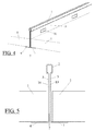
- Figure 4 shows a second embodiment of the ceiling system according to the invention, comprising vertical portions 3 of the support profiles 2 which include two walls which are spaced from each other and which are arranged to form spacing means between the opposed panels 1.
- Figure 5 shows the embodiment of figure 4 in cross-section. In this embodiment a gap or duct is defined between both walls of the double walled vertical portion 3 of the support profile 2. If necessary any form of support element(s) between both walls may be provided, preventing that the walls will be bent towards another under the weight of the panels and/or due to rough manipulation e.g. during installation of the ceiling. Such support elements, however, are not shown in figures 4 and 5 . At least one of both vertical walls 3 of the panel support profiles 2 are provided with one or more apertures 10 allowing air to flow into the duct or gap 7 between both vertical walls 2 (provided that the air flows downwards from the plenum to the room to be ventilated.
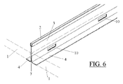
- Figure 6 shows a third embodiment of the ceiling system according to the invention
- figure 7 shows the same embodiment in cross-section.
- the vertical portion 3 of the panel support profile 2 is double walled.
- the upper side of the air duct/gap is (at both sides of the mainly vertical portion 3 of the support profile 2) defined by the space between the vertical portion 3 of the support profile 2 and the (vertical) side edge of the panel 1, which space is forced and maintained by means of the lower part of the vertical portion 3 of the support profile 2, which is bent outwards.
- This lower part functions, except as spacing means for spacing the opposite panels 1 and providing an upper part of the duct/gap between each panel edge and the upper part of the vertical profile portion, also for defining the lower part of the air gap/duct between both walls of the lower part of the (mainly) vertical profile portions bent outwards.
- spacing means for spacing the opposite panels 1 and providing an upper part of the duct/gap between each panel edge and the upper part of the vertical profile portion, also for defining the lower part of the air gap/duct between both walls of the lower part of the (mainly) vertical profile portions bent outwards.
- one or more apertures 10 are provided allowing air to flow through the duct/gap.
- Figure 8 shows an embodiment in which the cross-section of the mainly vertical portion 3 of the panel support profile 2 has been slightly amended compared with the cross-section of the embodiment shown in figures 6 and 7 .
Landscapes
- Engineering & Computer Science (AREA)
- Architecture (AREA)
- Physics & Mathematics (AREA)
- Electromagnetism (AREA)
- Civil Engineering (AREA)
- Structural Engineering (AREA)
- Building Environments (AREA)
Priority Applications (1)
| Application Number | Priority Date | Filing Date | Title |
|---|---|---|---|
| EP10159902A EP2378023A1 (de) | 2010-04-14 | 2010-04-14 | Deckensystem mit Rahmenwerk und Platten und mit Mitteln zur Erzeugung von Belüftungslücken |
Applications Claiming Priority (1)
| Application Number | Priority Date | Filing Date | Title |
|---|---|---|---|
| EP10159902A EP2378023A1 (de) | 2010-04-14 | 2010-04-14 | Deckensystem mit Rahmenwerk und Platten und mit Mitteln zur Erzeugung von Belüftungslücken |
Publications (1)
| Publication Number | Publication Date |
|---|---|
| EP2378023A1 true EP2378023A1 (de) | 2011-10-19 |
Family
ID=42562347
Family Applications (1)
| Application Number | Title | Priority Date | Filing Date |
|---|---|---|---|
| EP10159902A Ceased EP2378023A1 (de) | 2010-04-14 | 2010-04-14 | Deckensystem mit Rahmenwerk und Platten und mit Mitteln zur Erzeugung von Belüftungslücken |
Country Status (1)
| Country | Link |
|---|---|
| EP (1) | EP2378023A1 (de) |
Cited By (2)
| Publication number | Priority date | Publication date | Assignee | Title |
|---|---|---|---|---|
| WO2019191477A1 (en) | 2018-03-31 | 2019-10-03 | Certainteed Ceilings Corporation | Vented suspension ceiling beam and suspension ceiling system |
| EP4246049A1 (de) * | 2022-03-14 | 2023-09-20 | Saint-Gobain Ecophon AB | Diffusions-deckenlüftungssystem |
Citations (4)
| Publication number | Priority date | Publication date | Assignee | Title |
|---|---|---|---|---|
| US2859681A (en) * | 1956-03-28 | 1958-11-11 | Joel R Rachlin | Air-flow ceiling arrangements |
| US3101661A (en) * | 1961-07-18 | 1963-08-27 | Lok Products Co | T-runner |
| US3475869A (en) * | 1966-09-07 | 1969-11-04 | Chicago Metallic Sash Co | Ventilated suspended ceiling structure |
| WO2009005344A2 (en) | 2007-06-07 | 2009-01-08 | Nederlandse Organisatie Voor Toegepast-Natuurwetenschappelijk Onderzoek Tno | Ventilation system |
-
2010
- 2010-04-14 EP EP10159902A patent/EP2378023A1/de not_active Ceased
Patent Citations (4)
| Publication number | Priority date | Publication date | Assignee | Title |
|---|---|---|---|---|
| US2859681A (en) * | 1956-03-28 | 1958-11-11 | Joel R Rachlin | Air-flow ceiling arrangements |
| US3101661A (en) * | 1961-07-18 | 1963-08-27 | Lok Products Co | T-runner |
| US3475869A (en) * | 1966-09-07 | 1969-11-04 | Chicago Metallic Sash Co | Ventilated suspended ceiling structure |
| WO2009005344A2 (en) | 2007-06-07 | 2009-01-08 | Nederlandse Organisatie Voor Toegepast-Natuurwetenschappelijk Onderzoek Tno | Ventilation system |
Cited By (5)
| Publication number | Priority date | Publication date | Assignee | Title |
|---|---|---|---|---|
| WO2019191477A1 (en) | 2018-03-31 | 2019-10-03 | Certainteed Ceilings Corporation | Vented suspension ceiling beam and suspension ceiling system |
| US10858829B2 (en) | 2018-03-31 | 2020-12-08 | Certainteed Ceilings Corporation | Vented suspension ceiling beam and suspension ceiling system |
| EP3775427A4 (de) * | 2018-03-31 | 2021-12-22 | CertainTeed Ceilings Corporation | Hängedeckenbalken und hängedeckensystem mit belüftung |
| EP4246049A1 (de) * | 2022-03-14 | 2023-09-20 | Saint-Gobain Ecophon AB | Diffusions-deckenlüftungssystem |
| WO2023174787A1 (en) | 2022-03-14 | 2023-09-21 | Saint-Gobain Ecophon Ab | A diffuse ceiling ventilation system |
Similar Documents
| Publication | Publication Date | Title |
|---|---|---|
| US11199004B2 (en) | Apparatus and system for dynamic acoustic drop ceiling system and methods thereof | |
| US11434636B2 (en) | Ceiling baffle apparatus and ceiling baffle system for a dynamic acoustic ceiling and methods thereof | |
| US11773591B2 (en) | Apparatus and system for dynamic acoustic ceiling system and methods thereof | |
| CN104870725B (zh) | 吊顶系统 | |
| US3788206A (en) | Modular ceiling construction | |
| US10858829B2 (en) | Vented suspension ceiling beam and suspension ceiling system | |
| US20120317915A1 (en) | Self-Hanging Notched Ceiling Tile | |
| US20230383532A1 (en) | Apparatus and system for acoustic curved ceiling baffle and methods of manufacturing thereof | |
| EP2365152A1 (de) | Deckensystem mit Rahmenwerk und Platten und mit Mitteln zur Erzeugung von Belüftungslücken | |
| US6513295B2 (en) | Suspension system for false ceiling panels | |
| EP2378023A1 (de) | Deckensystem mit Rahmenwerk und Platten und mit Mitteln zur Erzeugung von Belüftungslücken | |
| US9803888B2 (en) | HVAC base and return air system | |
| US3506822A (en) | Universal air handling troffer frame | |
| CN108603372B (zh) | 悬挂式墙壁轨道系统 | |
| PH12016000389A1 (en) | Louver | |
| EP3656941A1 (de) | Vakuumisolationspaneelsystem | |
| JP6475999B2 (ja) | 建物の天井構造 | |
| EP2090707B1 (de) | Zimmerdecke und Verfahren zu deren Anbringung | |
| KR20130051082A (ko) | 천정판넬 시공장치 | |
| JPH11230608A (ja) | ユニット式建物の通風ダクトの接続構造 | |
| EP4246049A1 (de) | Diffusions-deckenlüftungssystem | |
| PL232361B1 (pl) | Stropowy element prefabrykowany | |
| WO1988003208A1 (en) | Installation ceiling | |
| EP2218844B1 (de) | Profil und Verfahren zur Befestigung eines Profils | |
| KR20170016624A (ko) | 크린룸의 천장판넬 시공장치 |
Legal Events
| Date | Code | Title | Description |
|---|---|---|---|
| AK | Designated contracting states |
Kind code of ref document: A1 Designated state(s): AT BE BG CH CY CZ DE DK EE ES FI FR GB GR HR HU IE IS IT LI LT LU LV MC MK MT NL NO PL PT RO SE SI SK SM TR |
|
| AX | Request for extension of the european patent |
Extension state: AL BA ME RS |
|
| PUAI | Public reference made under article 153(3) epc to a published international application that has entered the european phase |
Free format text: ORIGINAL CODE: 0009012 |
|
| STAA | Information on the status of an ep patent application or granted ep patent |
Free format text: STATUS: THE APPLICATION HAS BEEN REFUSED |
|
| 18R | Application refused |
Effective date: 20111125 |