US10856433B2 - Radiator and electric device - Google Patents
Radiator and electric device Download PDFInfo
- Publication number
- US10856433B2 US10856433B2 US15/779,885 US201615779885A US10856433B2 US 10856433 B2 US10856433 B2 US 10856433B2 US 201615779885 A US201615779885 A US 201615779885A US 10856433 B2 US10856433 B2 US 10856433B2
- Authority
- US
- United States
- Prior art keywords
- heat conductive
- radiator
- heat
- radiating part
- receiving section
- Prior art date
- Legal status (The legal status is an assumption and is not a legal conclusion. Google has not performed a legal analysis and makes no representation as to the accuracy of the status listed.)
- Active
Links
Images


Classifications
-
- H—ELECTRICITY
- H05—ELECTRIC TECHNIQUES NOT OTHERWISE PROVIDED FOR
- H05K—PRINTED CIRCUITS; CASINGS OR CONSTRUCTIONAL DETAILS OF ELECTRIC APPARATUS; MANUFACTURE OF ASSEMBLAGES OF ELECTRICAL COMPONENTS
- H05K7/00—Constructional details common to different types of electric apparatus
- H05K7/20—Modifications to facilitate cooling, ventilating, or heating
- H05K7/20009—Modifications to facilitate cooling, ventilating, or heating using a gaseous coolant in electronic enclosures
- H05K7/20136—Forced ventilation, e.g. by fans
- H05K7/20145—Means for directing air flow, e.g. ducts, deflectors, plenum or guides
-
- H01L23/467—
-
- H—ELECTRICITY
- H05—ELECTRIC TECHNIQUES NOT OTHERWISE PROVIDED FOR
- H05K—PRINTED CIRCUITS; CASINGS OR CONSTRUCTIONAL DETAILS OF ELECTRIC APPARATUS; MANUFACTURE OF ASSEMBLAGES OF ELECTRICAL COMPONENTS
- H05K7/00—Constructional details common to different types of electric apparatus
- H05K7/20—Modifications to facilitate cooling, ventilating, or heating
- H05K7/20009—Modifications to facilitate cooling, ventilating, or heating using a gaseous coolant in electronic enclosures
- H05K7/20136—Forced ventilation, e.g. by fans
- H05K7/20154—Heat dissipaters coupled to components
-
- H—ELECTRICITY
- H05—ELECTRIC TECHNIQUES NOT OTHERWISE PROVIDED FOR
- H05K—PRINTED CIRCUITS; CASINGS OR CONSTRUCTIONAL DETAILS OF ELECTRIC APPARATUS; MANUFACTURE OF ASSEMBLAGES OF ELECTRICAL COMPONENTS
- H05K7/00—Constructional details common to different types of electric apparatus
- H05K7/20—Modifications to facilitate cooling, ventilating, or heating
- H05K7/2029—Modifications to facilitate cooling, ventilating, or heating using a liquid coolant with phase change in electronic enclosures
- H05K7/20336—Heat pipes, e.g. wicks or capillary pumps
-
- H—ELECTRICITY
- H05—ELECTRIC TECHNIQUES NOT OTHERWISE PROVIDED FOR
- H05K—PRINTED CIRCUITS; CASINGS OR CONSTRUCTIONAL DETAILS OF ELECTRIC APPARATUS; MANUFACTURE OF ASSEMBLAGES OF ELECTRICAL COMPONENTS
- H05K7/00—Constructional details common to different types of electric apparatus
- H05K7/20—Modifications to facilitate cooling, ventilating, or heating
- H05K7/2039—Modifications to facilitate cooling, ventilating, or heating characterised by the heat transfer by conduction from the heat generating element to a dissipating body
- H05K7/20409—Outer radiating structures on heat dissipating housings, e.g. fins integrated with the housing
- H05K7/20418—Outer radiating structures on heat dissipating housings, e.g. fins integrated with the housing the radiating structures being additional and fastened onto the housing
-
- H—ELECTRICITY
- H05—ELECTRIC TECHNIQUES NOT OTHERWISE PROVIDED FOR
- H05K—PRINTED CIRCUITS; CASINGS OR CONSTRUCTIONAL DETAILS OF ELECTRIC APPARATUS; MANUFACTURE OF ASSEMBLAGES OF ELECTRICAL COMPONENTS
- H05K7/00—Constructional details common to different types of electric apparatus
- H05K7/20—Modifications to facilitate cooling, ventilating, or heating
- H05K7/2089—Modifications to facilitate cooling, ventilating, or heating for power electronics, e.g. for inverters for controlling motor
- H05K7/20909—Forced ventilation, e.g. on heat dissipaters coupled to components
-
- H—ELECTRICITY
- H10—SEMICONDUCTOR DEVICES; ELECTRIC SOLID-STATE DEVICES NOT OTHERWISE PROVIDED FOR
- H10W—GENERIC PACKAGES, INTERCONNECTIONS, CONNECTORS OR OTHER CONSTRUCTIONAL DETAILS OF DEVICES COVERED BY CLASS H10
- H10W40/00—Arrangements for thermal protection or thermal control
- H10W40/40—Arrangements for thermal protection or thermal control involving heat exchange by flowing fluids
- H10W40/43—Arrangements for thermal protection or thermal control involving heat exchange by flowing fluids by flowing gases, e.g. forced air cooling
-
- H01L23/427—
-
- H01L23/473—
-
- H—ELECTRICITY
- H10—SEMICONDUCTOR DEVICES; ELECTRIC SOLID-STATE DEVICES NOT OTHERWISE PROVIDED FOR
- H10W—GENERIC PACKAGES, INTERCONNECTIONS, CONNECTORS OR OTHER CONSTRUCTIONAL DETAILS OF DEVICES COVERED BY CLASS H10
- H10W40/00—Arrangements for thermal protection or thermal control
- H10W40/40—Arrangements for thermal protection or thermal control involving heat exchange by flowing fluids
- H10W40/47—Arrangements for thermal protection or thermal control involving heat exchange by flowing fluids by flowing liquids, e.g. forced water cooling
-
- H—ELECTRICITY
- H10—SEMICONDUCTOR DEVICES; ELECTRIC SOLID-STATE DEVICES NOT OTHERWISE PROVIDED FOR
- H10W—GENERIC PACKAGES, INTERCONNECTIONS, CONNECTORS OR OTHER CONSTRUCTIONAL DETAILS OF DEVICES COVERED BY CLASS H10
- H10W40/00—Arrangements for thermal protection or thermal control
- H10W40/70—Fillings or auxiliary members in containers or in encapsulations for thermal protection or control
- H10W40/73—Fillings or auxiliary members in containers or in encapsulations for thermal protection or control for cooling by change of state
Definitions
- At least one embodiment of present invention is generally related to a radiator and an electric device.
- the current heat radiating system is basically consisted of fans and cooling fins, the cooling fins are fixed on the heat source, the fans rotate the air to blow off the heated air around the cooling fins and to bring in new air, thus exchanging heat.
- the cooling fins are generally large.
- Various disclosed embodiments include radiators and electric devices.
- At least one embodiment is directed to a radiator.
- the radiator comprises:
- a radiating part including
- a heat conductive part including
- the receiving section is defined by the shell, and the receiving section is configured to receive the radiating part
- the radiating part is rotatablely fixed on the receiving section of the heat conductive part, when the radiating part rotates, fluid can be drawn into one end of the receiving section and then blown out at the other end by the blades.
- At least one embodiment is further directed to an electric device.
- the electric device includes
- a heat source further including the radiator according to any of the above-mentioned embodiments, the radiator being in contact with the heat source through the heat conductive surface.
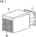
- FIG. 1 illustrates a heat dissipation system of the prior art
- FIG. 2 illustrates an exploded view of a radiator of an example embodiment of the present invention
- FIG. 3 illustrates a sectional view of a radiator of an example embodiment of the present invention.
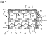
- FIG. 4 illustrates a radiator at work of an example embodiment of the present invention.
- a radiator comprises:
- a radiating part including
- a heat conductive part including
- the receiving section is defined by the shell, and the receiving section is configured to receive the radiating part
- the radiating part is rotatablely fixed on the receiving section of the heat conductive part, when the radiating part rotates, fluid can be drawn into one end of the receiving section and then blown out at the other end by the blades.
- the radiating part in at least one embodiment, is rotatable and able to exchange heat constantly with new fluid (e.g. air or cold water).
- new fluid e.g. air or cold water
- the rotation of the blades can expel the fluid with higher temperature and draw in fluid with lower temperature to perform new heat exchange, accelerating the contact speed of the fluid and the surface of the blades of the radiating part, resulting in a better heat exchange rate.
- a rotating shaft is arranged on the radiating part, the blades extend from the inner surface of the housing to the rotating shaft.
- the rotating shaft is able to rotate the radiating part as well as the blades, with better stability.
- the radiator further comprises heat conductive fluid
- the heat conductive fluid is in between the housing of the radiating part and the receiving section of the heat conductive part.
- Heat conductive fluid is adopted to diminish the thermal loss between the heat conductive part and the radiating part, resulting in a better heat conduction effect.
- the airflow generated by the rotation of the radiating part is able to take off more heat thus improving the radiating effect.
- the heat conductive fluid is defined in between the housing of the radiating part and the receiving section of the heat conductive part by a sealed bearing, so that the heat conductive fluid would not leak out.
- the radiating part is fixed in the receiving section of the heat conductive part by a bearing.
- the bearing can be a sealed bearing or other kinds of bearings; the bearing is able to fix the radiating part in the receiving section, making sure there is a certain space between the radiating part and the receiving part, avoiding direct friction against each other.
- the radiator further comprises a power unit, the power unit is configured to rotate the radiating part, to better control the rotation of the radiating part.
- the radiator further comprises a power unit which is fixed with the rotating shaft of the radiating part, the power unit is configured to rotate the radiating part.
- the integral structure is more stable by when the rotating shaft is directly connected to the power unit, the power unit is able to rotate the housing and further rotate the blades.
- the radiator further comprises a holder which is configured to fix the power unit on the heat conductive part.
- heat pipes are buried inside of the shell of the heat conductive part to further improve the heat exchange rate.
- At least one embodiment of the invention is further directed to an electric device.
- the electric device includes
- a heat source further including the radiator according to any of the above-mentioned embodiments, the radiator being in contact with the heat source through the heat conductive surface.
- the radiating part is able to rotate and exchange heat constantly with new fluid.
- the rotation of the blades can expel the fluid with higher temperature and draw in fluid with lower temperature to perform new heat exchange, accelerating the contact speed of the fluid and the surface of the blades of the radiating part, resulting in a better heat exchange rate without extra occupied volume of the electric device.
- FIGS. 1 through 4 discussed below, and the various embodiments used to describe the principles of the present disclosure in this patent document are by way of illustration only and should not be construed in any way to limit the scope of the disclosure.
- the numerous innovative teachings of the present application will be described with reference to example non-limiting embodiments.
- cooling fins 92 would remain static because they are fixed under the heat source 90 .
- Fans 91 would generate air flow while functioning which results in the fact that some cooling fins are close to the air passage while other cooling fins are far from the air passage.
- the air around those cooling fins which are close to the air passage moves faster thus leading to a higher heat exchange efficiency; the air around those cooling fins which are far from the air passage moves slower thus leading to a lower heat exchange efficiency. Therefore, the overall heat exchange of the heat dissipation system is unable to achieve the optimal efficiency. Meanwhile, to achieve better heat dissipation capability, the cooling fins are often large, making the volume of the electric device large accordingly.
- the present application provides an embodiment of a radiator, comprising a radiating part and a heat conductive part, wherein, the heat generated by the heat source can be conducted to the radiating part by the heat conductive part, and the radiating part is able to rotate.
- the radiating part rotates, fluid can be drawn into one end of and then blown out at the other end resulting in higher heat exchange efficiency.
- air is used as an example to illustrate how the radiator rotates and draws the fluid from one end then blows out the fluid from the other end.
- the specification should not be read as limiting the invention of the example air as described below, but to encompass other kinds of fluid such as cold water, fluid of room temperature, etc.
- the radiating part is able to draw in and discharge such fluid when rotating, thus cooling down the temperature.
- the radiating part 10 includes a housing 12 and a set of blades 14 arranged on the inner surface of the housing 12 .
- the blades 14 When the housing 12 rotates, the blades 14 would rotate along with the housing 12 , so that the air with lower temperature from outside can be drawn in.
- the heat conductive part 20 has a shell 22 .
- a heat conductive surface 23 which is in contact with the heat source 90 is arranged on the shell 22 so that the heat generated by the heat source can be conducted to the heat conductive part 20 .
- the heat conductive part 20 has a receiving section 24 with two open ends; the receiving section 24 can be approximately defined by the shell 22 , so that the radiating part 10 can be put into the receiving section 24 .
- the radiating part 10 can be rotateably fixed in the receiving section 24 of the heat conductive part 20 , a bearing 40 can be adopted to fix the radiating part 10 in the receiving section 24 so that there would be a certain space between the radiating part 10 and the receiving section 24 , avoiding direct friction against each other while remaining fixed.
- the heat conductive part 20 conducts heat to the radiating part 10 and further to the blades 14 by the air, when the radiating part 10 rotates, the air can be drawn into one end of the receiving section 24 and then blown out at the other end by the blades 14 .
- Heat conductive material 30 (e.g. silicone grease) as shown in the figure can also be applied in place of air. Heat conductive material 30 is of higher heat conducting efficiency and lower thermal loss. Heat conductive material 30 can be filled in between housing 12 of the radiating part 10 and the receiving section 24 of the heat conductive part 20 , and then sealed by the bearing 40 . Under such circumstances when heat conductive material 30 is adopted, the heat from the heat conductive part can be better conducted from the heat conductive part and further to the blades of the radiating part.
- Heat conductive material 30 e.g. silicone grease
- a power unit 50 which is capable of rotating the radiating part 10 , for example, a motor, can be arranged on the heat conductive part 20 through a holder 60 , so that the rotation of the radiating part 10 is in better control.
- FIG. 2 illustrates that a rotating shaft 13 is arranged inside of the radiating part 10 with the blades 14 extending from the inner surface of the housing 12 to the rotating shaft 13 .
- the rotating shaft 13 can be optional.
- the blades 14 of the radiating part 14 protrude from the inner surface of the housing 12 without the rotating shaft being installed.
- the housing 12 includes a connecting part that connects the power unit (not shown in the figure), the power unit rotates the housing and further rotates the blades.
- blades are arranged between the rotating shaft and the inner surface of the housing, it is also possible to further arrange some blades on the inner surface of the housing protrudingly, or further arrange some blades on the rotating shaft, or further arrange some blades both on the inner surface of the housing protrudingly and on the rotating shaft.
- heat spreading parts such as tubes 70 can be buried in the shell 22 of heat conductor 20 .
- heat source 90 is in contact with the heat conductor 20 through the heat conductive surface 23 ; the heat is conducted from the shell 22 of the heat conductor 20 to the radiating part 10 .
- the blades 14 are arranged on the housing 12 so that the heat can be conducted from the housing 12 to the blades 14 , at the same time, the heat conductive material 30 can better conduct the heat on the heat conductor 20 further to the blades 14 of the radiating part 10 .
- the rotating shaft 13 of the radiating part 10 is fixed to the power unit 50 , the power unit 50 is able to rotate the radiating part 10 , thus exchanging heat with new air constantly. It greatly accelerates the contact velocity of the air against the surface of the blades of the radiating part, thus improving the heat exchange efficiency.
- the present invention also provides an electric device, including a heat source 90 generating heat, meanwhile, the above-mentioned radiator can be arranged, the radiating part is in contact with the heat source through the heat conductive surface so that the heat of the heat source can be conducted to the radiating part.
- the radiating part is able to rotate the fluid and exchange heat constantly with fluid with relatively lower temperature, resulting in a better heat exchange rate without extra occupied volume of the electric device, so that the radiator is relatively small.
Landscapes
- Engineering & Computer Science (AREA)
- Microelectronics & Electronic Packaging (AREA)
- Physics & Mathematics (AREA)
- Thermal Sciences (AREA)
- Cooling Or The Like Of Electrical Apparatus (AREA)
- Heat-Exchange Devices With Radiators And Conduit Assemblies (AREA)
- Motor Or Generator Cooling System (AREA)
- Cooling Or The Like Of Semiconductors Or Solid State Devices (AREA)
Abstract
Description
-
- a housing; and
- a set of blades which are arranged on the inner surface of the housing,
-
- a shell, the shell has a heat conductive surface which is configured to be in contact with a heat source; and
-
- 10 radiating part
- 12 housing
- 13 rotating shaft
- 14 blades
- 20 heat conductive part
- 22 shell
- 23 heat conductive surface
- 24 receiving section
- 30 heat conductive fluid
- 40 bearing
- 50 power unit
- 60 holder
- 70 heat pipes
- 90 heat source
- 91 fans
-
- a housing; and
- a set of blades which are arranged on the inner surface of the housing,
-
- a shell, the shell has a heat conductive surface which is configured to be in contact with a heat source; and
Claims (16)
Applications Claiming Priority (1)
| Application Number | Priority Date | Filing Date | Title |
|---|---|---|---|
| PCT/CN2016/073878 WO2017139923A1 (en) | 2016-02-16 | 2016-02-16 | Radiator and electric device |
Publications (2)
| Publication Number | Publication Date |
|---|---|
| US20180343769A1 US20180343769A1 (en) | 2018-11-29 |
| US10856433B2 true US10856433B2 (en) | 2020-12-01 |
Family
ID=59624673
Family Applications (1)
| Application Number | Title | Priority Date | Filing Date |
|---|---|---|---|
| US15/779,885 Active US10856433B2 (en) | 2016-02-16 | 2016-02-16 | Radiator and electric device |
Country Status (4)
| Country | Link |
|---|---|
| US (1) | US10856433B2 (en) |
| EP (1) | EP3365915B1 (en) |
| CN (1) | CN108352369B (en) |
| WO (1) | WO2017139923A1 (en) |
Cited By (1)
| Publication number | Priority date | Publication date | Assignee | Title |
|---|---|---|---|---|
| US11662149B2 (en) | 2021-09-03 | 2023-05-30 | B/E Aerospace, Inc. | Layered diffuser channel heat exchanger |
Families Citing this family (3)
| Publication number | Priority date | Publication date | Assignee | Title |
|---|---|---|---|---|
| CN109398124A (en) * | 2018-09-26 | 2019-03-01 | 天长市天毅电子科技有限公司 | A kind of electric car charger |
| CN109362208A (en) * | 2018-10-27 | 2019-02-19 | 飞依诺科技(苏州)有限公司 | Rapid heat soaking device and handheld ultrasonic testing equipment |
| CN115151119A (en) * | 2021-03-29 | 2022-10-04 | 北京小米移动软件有限公司 | Electronic device |
Citations (13)
| Publication number | Priority date | Publication date | Assignee | Title |
|---|---|---|---|---|
| US6334713B1 (en) * | 1999-03-23 | 2002-01-01 | Roller Bearing Industries, Inc. | Bearing assembly having an improved wear ring liner |
| DE20205305U1 (en) | 2001-12-27 | 2002-08-14 | Wang, Chin-Wen, Ping Jen, Taoyuan | Rotation cooler of a CPU |
| CN2508394Y (en) | 2001-09-10 | 2002-08-28 | 王炯中 | Computer radiator |
| US6588498B1 (en) | 2002-07-18 | 2003-07-08 | Delphi Technologies, Inc. | Thermosiphon for electronics cooling with high performance boiling and condensing surfaces |
| CN1584339A (en) | 2003-08-21 | 2005-02-23 | 日本电产株式会社 | Centrifugal fan, cooling mechanism, and apparatus furnished with the cooling mechanism |
| US6945318B2 (en) * | 2004-01-26 | 2005-09-20 | Giga-Byte Technology Co., Ltd. | Heat-dissipating device |
| US20060082972A1 (en) * | 2004-10-20 | 2006-04-20 | Kyoung-Ho Kim | Heat radiating apparatus |
| US20060185821A1 (en) * | 2005-02-24 | 2006-08-24 | Comp Take Technology Co., Ltd. | Thermal dissipation device |
| US20100195284A1 (en) * | 2006-12-11 | 2010-08-05 | Danfoss Drives A/S | Electronic device and frequency converter of motor |
| US20120180992A1 (en) * | 2010-08-13 | 2012-07-19 | Koplow Jeffrey P | Axial flow heat exchanger devices and methods for heat transfer using axial flow devices |
| JP2013202637A (en) | 2012-03-27 | 2013-10-07 | Jfe Steel Corp | Guide roller |
| CN203481211U (en) | 2013-09-11 | 2014-03-12 | 广州市珠江灯光科技有限公司 | Spiral radiator |
| US20150116928A1 (en) | 2013-10-31 | 2015-04-30 | Microsoft Corporation | Centrifugal Fan with Integrated Thermal Transfer Unit |
Family Cites Families (1)
| Publication number | Priority date | Publication date | Assignee | Title |
|---|---|---|---|---|
| DE2635172A1 (en) * | 1976-08-05 | 1978-02-09 | Felten & Guilleaume Carlswerk | ELECTRIC MACHINE WITH SEALED ROLLER BEARINGS, LUBRICATED WITH GREASE |
-
2016
- 2016-02-16 EP EP16890158.5A patent/EP3365915B1/en active Active
- 2016-02-16 WO PCT/CN2016/073878 patent/WO2017139923A1/en not_active Ceased
- 2016-02-16 US US15/779,885 patent/US10856433B2/en active Active
- 2016-02-16 CN CN201680053267.4A patent/CN108352369B/en active Active
Patent Citations (19)
| Publication number | Priority date | Publication date | Assignee | Title |
|---|---|---|---|---|
| US6334713B1 (en) * | 1999-03-23 | 2002-01-01 | Roller Bearing Industries, Inc. | Bearing assembly having an improved wear ring liner |
| CN2508394Y (en) | 2001-09-10 | 2002-08-28 | 王炯中 | Computer radiator |
| DE20205305U1 (en) | 2001-12-27 | 2002-08-14 | Wang, Chin-Wen, Ping Jen, Taoyuan | Rotation cooler of a CPU |
| US20030123227A1 (en) | 2001-12-27 | 2003-07-03 | Wang Chin-Wen | Rotary cooler of CPU |
| US6588498B1 (en) | 2002-07-18 | 2003-07-08 | Delphi Technologies, Inc. | Thermosiphon for electronics cooling with high performance boiling and condensing surfaces |
| US20060056964A9 (en) | 2003-08-21 | 2006-03-16 | Nidec Corporation | Centrifugal Fan, Cooling Mechanism, and Apparatus Furnished with the Cooling Mechanism |
| US20050042082A1 (en) | 2003-08-21 | 2005-02-24 | Nidec Corporation | Centrifugal Fan, Cooling Mechanism, and Apparatus Furnished with the Cooling Mechanism |
| CN1584339A (en) | 2003-08-21 | 2005-02-23 | 日本电产株式会社 | Centrifugal fan, cooling mechanism, and apparatus furnished with the cooling mechanism |
| US6945318B2 (en) * | 2004-01-26 | 2005-09-20 | Giga-Byte Technology Co., Ltd. | Heat-dissipating device |
| US20060082972A1 (en) * | 2004-10-20 | 2006-04-20 | Kyoung-Ho Kim | Heat radiating apparatus |
| US20060185821A1 (en) * | 2005-02-24 | 2006-08-24 | Comp Take Technology Co., Ltd. | Thermal dissipation device |
| US20100195284A1 (en) * | 2006-12-11 | 2010-08-05 | Danfoss Drives A/S | Electronic device and frequency converter of motor |
| US20120180992A1 (en) * | 2010-08-13 | 2012-07-19 | Koplow Jeffrey P | Axial flow heat exchanger devices and methods for heat transfer using axial flow devices |
| WO2012118982A2 (en) | 2011-03-02 | 2012-09-07 | Sandia Corporation | Axial flow heat exchanger devices and methods for heat transfer using axial flow devices |
| US20160116232A1 (en) * | 2011-03-02 | 2016-04-28 | Sandia Corporation | Axial flow heat exchanger devices and methods for heat transfer using axial flow devices |
| JP2013202637A (en) | 2012-03-27 | 2013-10-07 | Jfe Steel Corp | Guide roller |
| CN203481211U (en) | 2013-09-11 | 2014-03-12 | 广州市珠江灯光科技有限公司 | Spiral radiator |
| US20150116928A1 (en) | 2013-10-31 | 2015-04-30 | Microsoft Corporation | Centrifugal Fan with Integrated Thermal Transfer Unit |
| WO2015065926A1 (en) | 2013-10-31 | 2015-05-07 | Microsoft Corporation | Centrifugal fan with integrated thermal transfer unit |
Non-Patent Citations (3)
| Title |
|---|
| Extended European Search Report for European Patent Application No. 16890158.5 dated Apr. 30, 2019. |
| International Search Report PCT/ISA/210 for International Application No. PCT/CN2016/073878 Dated Feb. 16, 2016. |
| Written Opinion of the International Searching Authority PCT/ISA/237 for International Application No. PCT/CN2016/073878 Dated Feb. 16, 2016. |
Cited By (1)
| Publication number | Priority date | Publication date | Assignee | Title |
|---|---|---|---|---|
| US11662149B2 (en) | 2021-09-03 | 2023-05-30 | B/E Aerospace, Inc. | Layered diffuser channel heat exchanger |
Also Published As
| Publication number | Publication date |
|---|---|
| CN108352369B (en) | 2022-12-20 |
| EP3365915C0 (en) | 2025-06-11 |
| EP3365915A4 (en) | 2019-05-29 |
| EP3365915B1 (en) | 2025-06-11 |
| CN108352369A (en) | 2018-07-31 |
| US20180343769A1 (en) | 2018-11-29 |
| EP3365915A1 (en) | 2018-08-29 |
| WO2017139923A1 (en) | 2017-08-24 |
Similar Documents
| Publication | Publication Date | Title |
|---|---|---|
| US10856433B2 (en) | Radiator and electric device | |
| CN101765353B (en) | Heat-dissipation module | |
| US7481263B2 (en) | Cooling apparatus | |
| CN110707870B (en) | Inverter integrated motor | |
| CN109314440B (en) | Cooling device and method for power tools | |
| CN110313117B (en) | electric motor | |
| CN102244423A (en) | Motor | |
| CN111327157B (en) | Electric Motors and Aircraft | |
| US10760578B2 (en) | Vacuum pump with heat generation element in relation to housing | |
| JP2015215149A (en) | Air conditioner outdoor unit | |
| JP6622509B2 (en) | Electric motor cooling device | |
| US20180128153A1 (en) | Cooling fan using surface cooling effect for rotating fan blade part | |
| JP2006049382A (en) | Cooling device and electronic equipment | |
| US7117931B2 (en) | Systems for low cost liquid cooling | |
| KR102173886B1 (en) | Air cooling of the electronics of a bldc motor | |
| US20150077933A1 (en) | Electric machine with closed circuit air cooling | |
| JP2018141375A (en) | Integrated power type vacuum pump | |
| CN112888860B (en) | Rotor mounting unit with cooling function | |
| TWI572125B (en) | Rotor heat dissipation structure of inner rotor motor | |
| CN113794311B (en) | Heat dissipation end cover and motor | |
| JP4951774B2 (en) | Motor cooling structure and motor | |
| KR20040059944A (en) | Motor radiation module | |
| CN218941655U (en) | Heat abstractor of daily electrical apparatus | |
| EP1498684A1 (en) | Heat-dissipating device | |
| US20140158327A1 (en) | Water cooling apparatus |
Legal Events
| Date | Code | Title | Description |
|---|---|---|---|
| FEPP | Fee payment procedure |
Free format text: ENTITY STATUS SET TO UNDISCOUNTED (ORIGINAL EVENT CODE: BIG.); ENTITY STATUS OF PATENT OWNER: LARGE ENTITY |
|
| AS | Assignment |
Owner name: SIEMENS NUMERICAL CONTROL LTD., CHINA Free format text: ASSIGNMENT OF ASSIGNORS INTEREST;ASSIGNOR:ZHOU, YAN HENG;REEL/FRAME:046847/0616 Effective date: 20180528 |
|
| AS | Assignment |
Owner name: SIEMENS AKTIENGESELLSCHAFT, GERMANY Free format text: ASSIGNMENT OF ASSIGNORS INTEREST;ASSIGNOR:SIEMENS NUMERICAL CONTROL LTD.;REEL/FRAME:046896/0166 Effective date: 20180531 |
|
| STPP | Information on status: patent application and granting procedure in general |
Free format text: NON FINAL ACTION MAILED |
|
| STPP | Information on status: patent application and granting procedure in general |
Free format text: RESPONSE TO NON-FINAL OFFICE ACTION ENTERED AND FORWARDED TO EXAMINER |
|
| STPP | Information on status: patent application and granting procedure in general |
Free format text: FINAL REJECTION MAILED |
|
| STPP | Information on status: patent application and granting procedure in general |
Free format text: ADVISORY ACTION MAILED |
|
| STPP | Information on status: patent application and granting procedure in general |
Free format text: DOCKETED NEW CASE - READY FOR EXAMINATION |
|
| STPP | Information on status: patent application and granting procedure in general |
Free format text: NON FINAL ACTION MAILED |
|
| STPP | Information on status: patent application and granting procedure in general |
Free format text: RESPONSE TO NON-FINAL OFFICE ACTION ENTERED AND FORWARDED TO EXAMINER |
|
| STPP | Information on status: patent application and granting procedure in general |
Free format text: FINAL REJECTION MAILED |
|
| STPP | Information on status: patent application and granting procedure in general |
Free format text: NOTICE OF ALLOWANCE MAILED -- APPLICATION RECEIVED IN OFFICE OF PUBLICATIONS |
|
| STPP | Information on status: patent application and granting procedure in general |
Free format text: PUBLICATIONS -- ISSUE FEE PAYMENT RECEIVED |
|
| STCF | Information on status: patent grant |
Free format text: PATENTED CASE |
|
| MAFP | Maintenance fee payment |
Free format text: PAYMENT OF MAINTENANCE FEE, 4TH YEAR, LARGE ENTITY (ORIGINAL EVENT CODE: M1551); ENTITY STATUS OF PATENT OWNER: LARGE ENTITY Year of fee payment: 4 |