US10829976B2 - Lid stay for furniture - Google Patents
Lid stay for furniture Download PDFInfo
- Publication number
- US10829976B2 US10829976B2 US16/260,766 US201916260766A US10829976B2 US 10829976 B2 US10829976 B2 US 10829976B2 US 201916260766 A US201916260766 A US 201916260766A US 10829976 B2 US10829976 B2 US 10829976B2
- Authority
- US
- United States
- Prior art keywords
- arm
- setting
- spring
- lid
- flat
- Prior art date
- Legal status (The legal status is an assumption and is not a legal conclusion. Google has not performed a legal analysis and makes no representation as to the accuracy of the status listed.)
- Active
Links
- 239000000463 material Substances 0.000 claims abstract description 23
- 230000008878 coupling Effects 0.000 claims description 14
- 238000010168 coupling process Methods 0.000 claims description 14
- 238000005859 coupling reaction Methods 0.000 claims description 14
- 239000002184 metal Substances 0.000 claims description 8
- 229920002430 Fibre-reinforced plastic Polymers 0.000 description 2
- 230000007423 decrease Effects 0.000 description 2
- 239000011151 fibre-reinforced plastic Substances 0.000 description 2
- 229910000639 Spring steel Inorganic materials 0.000 description 1
- 229910000831 Steel Inorganic materials 0.000 description 1
- 239000002131 composite material Substances 0.000 description 1
- 239000013013 elastic material Substances 0.000 description 1
- 238000009434 installation Methods 0.000 description 1
- 238000004519 manufacturing process Methods 0.000 description 1
- 239000007769 metal material Substances 0.000 description 1
- 239000010421 standard material Substances 0.000 description 1
- 239000010959 steel Substances 0.000 description 1
- 239000000126 substance Substances 0.000 description 1
Images


Classifications
-
- E—FIXED CONSTRUCTIONS
- E05—LOCKS; KEYS; WINDOW OR DOOR FITTINGS; SAFES
- E05D—HINGES OR SUSPENSION DEVICES FOR DOORS, WINDOWS OR WINGS
- E05D11/00—Additional features or accessories of hinges
- E05D11/10—Devices for preventing movement between relatively-movable hinge parts
- E05D11/1028—Devices for preventing movement between relatively-movable hinge parts for maintaining the hinge in two or more positions, e.g. intermediate or fully open
-
- A—HUMAN NECESSITIES
- A47—FURNITURE; DOMESTIC ARTICLES OR APPLIANCES; COFFEE MILLS; SPICE MILLS; SUCTION CLEANERS IN GENERAL
- A47B—TABLES; DESKS; OFFICE FURNITURE; CABINETS; DRAWERS; GENERAL DETAILS OF FURNITURE
- A47B97/00—Furniture or accessories for furniture, not provided for in other groups of this subclass
-
- E—FIXED CONSTRUCTIONS
- E05—LOCKS; KEYS; WINDOW OR DOOR FITTINGS; SAFES
- E05D—HINGES OR SUSPENSION DEVICES FOR DOORS, WINDOWS OR WINGS
- E05D11/00—Additional features or accessories of hinges
- E05D11/10—Devices for preventing movement between relatively-movable hinge parts
-
- E—FIXED CONSTRUCTIONS
- E05—LOCKS; KEYS; WINDOW OR DOOR FITTINGS; SAFES
- E05D—HINGES OR SUSPENSION DEVICES FOR DOORS, WINDOWS OR WINGS
- E05D11/00—Additional features or accessories of hinges
- E05D11/10—Devices for preventing movement between relatively-movable hinge parts
- E05D11/1028—Devices for preventing movement between relatively-movable hinge parts for maintaining the hinge in two or more positions, e.g. intermediate or fully open
- E05D11/105—Devices for preventing movement between relatively-movable hinge parts for maintaining the hinge in two or more positions, e.g. intermediate or fully open the maintaining means acting perpendicularly to the pivot axis
- E05D11/1064—Devices for preventing movement between relatively-movable hinge parts for maintaining the hinge in two or more positions, e.g. intermediate or fully open the maintaining means acting perpendicularly to the pivot axis with a coil spring perpendicular to the pivot axis
-
- E—FIXED CONSTRUCTIONS
- E05—LOCKS; KEYS; WINDOW OR DOOR FITTINGS; SAFES
- E05D—HINGES OR SUSPENSION DEVICES FOR DOORS, WINDOWS OR WINGS
- E05D15/00—Suspension arrangements for wings
- E05D15/40—Suspension arrangements for wings supported on arms movable in vertical planes
-
- E—FIXED CONSTRUCTIONS
- E05—LOCKS; KEYS; WINDOW OR DOOR FITTINGS; SAFES
- E05F—DEVICES FOR MOVING WINGS INTO OPEN OR CLOSED POSITION; CHECKS FOR WINGS; WING FITTINGS NOT OTHERWISE PROVIDED FOR, CONCERNED WITH THE FUNCTIONING OF THE WING
- E05F1/00—Closers or openers for wings, not otherwise provided for in this subclass
- E05F1/08—Closers or openers for wings, not otherwise provided for in this subclass spring-actuated, e.g. for horizontally sliding wings
- E05F1/10—Closers or openers for wings, not otherwise provided for in this subclass spring-actuated, e.g. for horizontally sliding wings for swinging wings, e.g. counterbalance
- E05F1/1041—Closers or openers for wings, not otherwise provided for in this subclass spring-actuated, e.g. for horizontally sliding wings for swinging wings, e.g. counterbalance with a coil spring perpendicular to the pivot axis
- E05F1/105—Closers or openers for wings, not otherwise provided for in this subclass spring-actuated, e.g. for horizontally sliding wings for swinging wings, e.g. counterbalance with a coil spring perpendicular to the pivot axis with a compression spring
- E05F1/1058—Closers or openers for wings, not otherwise provided for in this subclass spring-actuated, e.g. for horizontally sliding wings for swinging wings, e.g. counterbalance with a coil spring perpendicular to the pivot axis with a compression spring for counterbalancing
-
- E—FIXED CONSTRUCTIONS
- E05—LOCKS; KEYS; WINDOW OR DOOR FITTINGS; SAFES
- E05F—DEVICES FOR MOVING WINGS INTO OPEN OR CLOSED POSITION; CHECKS FOR WINGS; WING FITTINGS NOT OTHERWISE PROVIDED FOR, CONCERNED WITH THE FUNCTIONING OF THE WING
- E05F1/00—Closers or openers for wings, not otherwise provided for in this subclass
- E05F1/08—Closers or openers for wings, not otherwise provided for in this subclass spring-actuated, e.g. for horizontally sliding wings
- E05F1/10—Closers or openers for wings, not otherwise provided for in this subclass spring-actuated, e.g. for horizontally sliding wings for swinging wings, e.g. counterbalance
- E05F1/1083—Closers or openers for wings, not otherwise provided for in this subclass spring-actuated, e.g. for horizontally sliding wings for swinging wings, e.g. counterbalance with a leaf or similar spring
-
- E—FIXED CONSTRUCTIONS
- E05—LOCKS; KEYS; WINDOW OR DOOR FITTINGS; SAFES
- E05F—DEVICES FOR MOVING WINGS INTO OPEN OR CLOSED POSITION; CHECKS FOR WINGS; WING FITTINGS NOT OTHERWISE PROVIDED FOR, CONCERNED WITH THE FUNCTIONING OF THE WING
- E05F1/00—Closers or openers for wings, not otherwise provided for in this subclass
- E05F1/08—Closers or openers for wings, not otherwise provided for in this subclass spring-actuated, e.g. for horizontally sliding wings
- E05F1/10—Closers or openers for wings, not otherwise provided for in this subclass spring-actuated, e.g. for horizontally sliding wings for swinging wings, e.g. counterbalance
- E05F1/12—Mechanisms in the shape of hinges or pivots, operated by springs
-
- E—FIXED CONSTRUCTIONS
- E05—LOCKS; KEYS; WINDOW OR DOOR FITTINGS; SAFES
- E05Y—INDEXING SCHEME ASSOCIATED WITH SUBCLASSES E05D AND E05F, RELATING TO CONSTRUCTION ELEMENTS, ELECTRIC CONTROL, POWER SUPPLY, POWER SIGNAL OR TRANSMISSION, USER INTERFACES, MOUNTING OR COUPLING, DETAILS, ACCESSORIES, AUXILIARY OPERATIONS NOT OTHERWISE PROVIDED FOR, APPLICATION THEREOF
- E05Y2201/00—Constructional elements; Accessories therefor
- E05Y2201/40—Motors; Magnets; Springs; Weights; Accessories therefor
- E05Y2201/47—Springs
- E05Y2201/48—Leaf or leg springs
-
- E—FIXED CONSTRUCTIONS
- E05—LOCKS; KEYS; WINDOW OR DOOR FITTINGS; SAFES
- E05Y—INDEXING SCHEME ASSOCIATED WITH SUBCLASSES E05D AND E05F, RELATING TO CONSTRUCTION ELEMENTS, ELECTRIC CONTROL, POWER SUPPLY, POWER SIGNAL OR TRANSMISSION, USER INTERFACES, MOUNTING OR COUPLING, DETAILS, ACCESSORIES, AUXILIARY OPERATIONS NOT OTHERWISE PROVIDED FOR, APPLICATION THEREOF
- E05Y2201/00—Constructional elements; Accessories therefor
- E05Y2201/60—Suspension or transmission members; Accessories therefor
- E05Y2201/622—Suspension or transmission members elements
- E05Y2201/638—Cams; Ramps
-
- E—FIXED CONSTRUCTIONS
- E05—LOCKS; KEYS; WINDOW OR DOOR FITTINGS; SAFES
- E05Y—INDEXING SCHEME ASSOCIATED WITH SUBCLASSES E05D AND E05F, RELATING TO CONSTRUCTION ELEMENTS, ELECTRIC CONTROL, POWER SUPPLY, POWER SIGNAL OR TRANSMISSION, USER INTERFACES, MOUNTING OR COUPLING, DETAILS, ACCESSORIES, AUXILIARY OPERATIONS NOT OTHERWISE PROVIDED FOR, APPLICATION THEREOF
- E05Y2800/00—Details, accessories and auxiliary operations not otherwise provided for
- E05Y2800/20—Combinations of elements
- E05Y2800/205—Combinations of elements forming a unit
-
- E—FIXED CONSTRUCTIONS
- E05—LOCKS; KEYS; WINDOW OR DOOR FITTINGS; SAFES
- E05Y—INDEXING SCHEME ASSOCIATED WITH SUBCLASSES E05D AND E05F, RELATING TO CONSTRUCTION ELEMENTS, ELECTRIC CONTROL, POWER SUPPLY, POWER SIGNAL OR TRANSMISSION, USER INTERFACES, MOUNTING OR COUPLING, DETAILS, ACCESSORIES, AUXILIARY OPERATIONS NOT OTHERWISE PROVIDED FOR, APPLICATION THEREOF
- E05Y2900/00—Application of doors, windows, wings or fittings thereof
- E05Y2900/20—Application of doors, windows, wings or fittings thereof for furniture, e.g. cabinets
Definitions
- the present disclosure relates to a lid stay for [[a]] furniture having a setting arm, which is pivotably attached on a base element around a first setting axis between an open position and a closed position, and having an energy accumulator which is coupled to the setting arm in such a way that the setting arm is subjected to force along at least a part of the pivot path of the setting arm in direction towards the open position or closed position.
- DE 102 23 026 B3 describes a lid stay with a setting slider which is guided linearly displaceably in a housing.
- the setting slider has a roller which is rotatably mounted on the setting slider. The roller is acted upon by a force into abutment to a setting contour of the setting arm.
- helical springs are used, which urge the setting slider and, thus, the roller against the setting contour.
- lid stays use helical springs.
- the helical springs have a proportionally large diameter. This leads to the fact, that the whole lid stay is formed relative thick in direction of the first pivot axis. This means, that the lid stay projects relatively far into the interior of the body of the furniture.
- a lid stay for a furniture has a setting arm which is pivotably attached on a base element around a first setting axis between an open position and a closed position, and an energy accumulator which is coupled to the setting arm in such a way that the setting arm is subjected to force along at least a part of the pivot path of the setting arm in direction towards the open position or the closed position.
- the energy accumulator comprises a flat spring, made from a plate-like flat material, wherein the flat spring is supported elastically on the base element and the setting arm in a plate plane of the flat material.
- the flat spring from a plate-like material is elastically loaded in the plate plane of the flat material.
- the terms “plate-like” and “flat material” mean in this connection, that the flat spring has a larger extension in a width direction and a length direction than in a thickness direction transversally to the plate plane.
- the flat spring is still to be regarded as plate-like in the sense of this disclosure if at least the essential part of the flat spring is arranged in the plate plane and potentially some areas are bent thereto.
- the flat spring is deformed elastically in the plate plane of the flat material and not, like a leaf spring, transversally to the plate plane of the flat material. Thus, a very thin structure of the lid stay is ensured.
- the flat spring is formed in the plate plane (parallel) to the plate plane elastically, so that the flat spring takes up along its plate thickness (thickness direction) no installation space.
- the plate plane is the plane, which is formed by the plate-like material.
- the plate thickness means the thickness of the plate-like material.
- the flat spring may be manufactured from metal sheet.
- standard materials like steel materials, especially spring steel, is used, which have been tried and tested in the manufacture of spring elements because of their flexibility and durability.
- the flat spring can however also be manufactured from a different material, like for example fibre-reinforced plastics or a composite component from metal and fibre-reinforced plastics.
- the flat spring can be formed U-like in the plate plane of the flat material and forms a first spring arm and a second spring arm, wherein the first spring arm is connected to the base element and the second spring arm is coupled to the setting arm for the force application.
- the U-like flat spring can be formed such, that the two spring arms are connected to each other via a turn section.
- the first spring arm has a first free end, with which the flat spring is connected, preferably rotatably, to the base element. Furthermore, the second spring arm may have a second free end, with which the flat spring is coupled to the setting arm. Thus, an as large as possible length of the flat spring can be used from the first free end up to the second free end.
- the spring arms can be formed tapered up to the free ends.
- the plate thickness does not change.
- the flat spring can be formed tapered from an apex of the turn section to the free ends in the plate plane.
- the second spring arm is coupled via a coupling device to the setting arm.
- the coupling device can have a setting contour on the setting arm which extends at a changing distance to the first setting axis.
- the coupling device can further have a pressure element which is acted upon by a force of the flat spring against the setting contour.
- the pressure element can for example be arranged on a pivot arm which is connected pivotably to the base element wherein the second spring arm is acted on against the pivot arm.
- the degrees of freedom for the movement of the flat spring and the coupling device are defined.
- the second spring arm can be connected, for instance rotatably, to the pivot arm.
- the pressure element can be a roller which is rotatably attached on the pivot arm.
- the flat spring can be formed S-like or W-like in the plate plane of the flat material.
- Other forms are also possible, like for example several wave-like portions, arranged one after the other and which are connected at their facing wave crests to each other, or any grid structures.
- FIG. 1 is a perspective representation of a furniture with a lid stay in the open position with a first embodiment of a flat spring
- FIG. 2 is a partial side view of the furniture body and of the lid stay of FIG. 1 with the lid stay in its closed position;
- FIG. 3 is a perspective representation of a lid stay of FIG. 1 in its open position
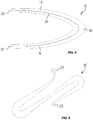
- FIG. 4 is a top view of a second embodiment of a flat spring in U-shape
- FIG. 5 is a top view of a third embodiment of a flat spring in S-shape
- FIG. 6 is a top view of a fourth embodiment of a flat spring in W-shape
- FIG. 7 is a top view of a fifth embodiment of a flat spring in wave shape.
- FIG. 8 is a top view of a sixth embodiment of a flat spring in grid shape.
- FIGS. 1 to 3 show a lid stay shown partially assembled in a body of a furniture, wherein the Figures are described together in the following.
- FIG. 1 shows a lid stay 1 mounted in a furniture 2 .
- the furniture 2 comprises a body 3 with two side walls 4 , 5 , a lower shelf 6 and an upper shelf 7 .
- the side walls 4 , 5 , the lower shelf 6 and the upper shelf 7 form together an opening 8 , which is closed by a folding lid 9 .
- the folding lid is shown in an open position.
- the folding lid has an upper lid half 10 which is pivotably connected around a horizontally arranged axis in the area of the upper shelf 7 6 to the body 3 .
- the upper lid half 10 is pivotably connected to a lower lid half 11 .
- the lid stay 1 is mounted on one of the side walls 4 , wherein a setting arm 12 of the lid stay 1 is pivotably connected around a first pivot axis S 1 to a base element 13 of the lid stay 1 between an open position ( FIGS. 1 and 3 ) and a closed position ( FIG. 2 ).
- the first pivot axis S 1 is arranged horizontally.
- the setting arm 12 is pivotably connected to the lower lid half 11 of the folding lid 9 around a second pivot axis S 2 , which is arranged parallel to the first pivot axis S 1 .
- the lid stay 1 can be connected also to a simple lid, i.e. a lid, which is not foldable. Furthermore, the lid stay 1 can also be provided as a fitting, which at the same time serves as hinge for the lid, so that the lid does not have to be connected via a further hinge to the body.
- the base element has a covering plate, which is shown in FIG. 1 .
- the covering plate is not shown, so that the interior of the lid stay 1 is visible.
- an energy accumulator 14 is provided which is coupled to the setting arm 12 in such a way that the setting arm 12 is subjected to a force along at least a part of its pivot path between the open position and the closed position, e.g., between an intermediate position and the open position and/or between an intermediate position and the closed position wherein the intermediate position is arranged between the open position and the closed position.
- the energy accumulator 14 has a flat spring 15 which is manufactured from a plate-like elastic material, for instance a sheet made from a metal material.
- plate-like means that the flat spring is many times thinner in the direction of its thickness than in a direction transverse to the thickness direction.
- the flat spring 15 has a first spring arm 16 and a second spring arm 17 which are connected to each other via a turn section 18 .
- the first spring arm 16 has a first free end 21 and the second spring arm 17 has a second free end 22 .
- the two free ends 21 , 22 face at least approximately in the same direction.
- the first free end 21 of the first spring arm 16 is pivotably connected to the base element 13 .
- the first free end 21 is connected via a rivet 19 to the base element 13 , so that the first spring arm 16 can pivot around the rivet 19 .
- the second free end 22 of the second spring arm 17 is coupled via a coupling device 20 to the setting arm 12 .
- the flat spring 15 is biased such, that a force of the second spring arm 17 acts on the setting arm 12 .
- the two spring arms 16 , 17 are biased away from each other, so that these act with a force towards each other.
- the flat spring 15 is biased in the plate plane of the plate-like material.
- the plate plane corresponds to the drawing page plane in FIGS. 2 and 4 to 8 .
- the coupling device 20 comprises an assembly unit 24 , on which the second free end 22 of the second spring arm 17 is pivotably connected via a bolt 23 .
- the assembly unit 24 is fixed to a pivot arm 25 which is connected pivotably around a third pivot axis S 3 to the base element 13 .
- the third pivot axis S 3 is arranged parallel to the first pivot axis S 1 and the second pivot axis S 2 .
- a roller 27 is rotatably supported via a bolt 26 on the assembly unit 24 .
- the roller 27 is acted on by a force against a setting contour 28 of a cam disc 29 , wherein the cam disc 29 is fixed to the setting arm 12 .
- the cam disc 29 is connected in the shown embodiment to the setting arm 12 for example by rivets. It is, however, also generally possible, that the cam disc is an integral part of the setting arm 12 .
- the second spring arm 17 can also be coupled directly, i.e. not via an assembly unit, to the pivot arm 25 .
- the roller 27 can be arranged directly rotatably on the pivot arm 25 .
- a pressure piece can be held in sliding abutment to the setting contour 28 .
- the setting contour 28 has a changing distance along its extension to the first pivot axis S 1 (i.e., between an outer edge of the setting contour 28 where the roller 27 contacts the cam disc 29 and the first pivot axis S 1 ), so that thus a force of the roller 27 acts on the setting arm 12 , which causes a torque in the pulling-in direction to the closed position and/or in the direction to the open position.
- the setting contour 28 can be formed such that the radial distance of the setting contour 28 to the first pivot axis S 1 in the contact area between the roller 27 and the setting contour 28 decreases via a pivot path starting from an intermediate position of the setting arm 12 between an open position and a the closed position in the direction towards the open position via an angular path of the setting arm 12 .
- the setting arm 12 is acted upon by a force across the largest angular path, which produces a torque in the direction to the open position.
- the setting contour 28 can have a shape, across which extension the radial distance between an outer edge of the setting contour 28 where the roller 27 contacts the cam disc 29 decreases to the first setting axis S 1 .
- a torque is produced, which urges the setting arm 12 to the closed position.
- the setting contour 28 can be formed such, that the produced torque corresponds in each pivot position of the setting arm 12 to a that counter-torque, which is produced in total by the weight force of the lid 9 , so that the lid 9 is held in any position between the open position and the intermediate position by the lid stay 1 .
- FIGS. 4 to 8 show exemplary further embodiments of flat springs, wherein components or elements, which correspond to those of the first embodiment, are provided with the same reference numerals and are described with the first embodiment.
- FIG. 4 shows a top view of a flat spring in U-shape, wherein along the extension of the flat spring within the U-shaped portion a slot 30 is provided, which ensures an increased elasticity of the flat spring in the plate plane.
- FIG. 5 shows a flat spring in S-shape.
- FIG. 6 shows a flat spring in W-shape.
- FIG. 7 shows a flat spring in wave shape, in which several wave-like elements 31 are arranged one behind the other, wherein the wave-like elements 31 are connected at their neighbouring wave crests 32 to each other. The individual elements can be joined together or can be integrally connected to each other.
- FIG. 8 shows a flat spring with a grid structure.
- the phrase at least one of A, B, and C should be construed to mean a logical (A OR B OR C), using a non-exclusive logical OR, and should not be construed to mean “at least one of A, at least one of B, and at least one of C.”
Landscapes
- Engineering & Computer Science (AREA)
- Mechanical Engineering (AREA)
- Closing And Opening Devices For Wings, And Checks For Wings (AREA)
- Springs (AREA)
- Extensible Doors And Revolving Doors (AREA)
- Cabinets, Racks, Or The Like Of Rigid Construction (AREA)
- Manipulator (AREA)
Abstract
Description
Claims (20)
Applications Claiming Priority (3)
| Application Number | Priority Date | Filing Date | Title |
|---|---|---|---|
| EP18154405 | 2018-01-31 | ||
| EP18154405.7 | 2018-01-31 | ||
| EP18154405.7A EP3521542B1 (en) | 2018-01-31 | 2018-01-31 | Cover positioner for furniture |
Publications (2)
| Publication Number | Publication Date |
|---|---|
| US20190234127A1 US20190234127A1 (en) | 2019-08-01 |
| US10829976B2 true US10829976B2 (en) | 2020-11-10 |
Family
ID=61132144
Family Applications (1)
| Application Number | Title | Priority Date | Filing Date |
|---|---|---|---|
| US16/260,766 Active US10829976B2 (en) | 2018-01-31 | 2019-01-29 | Lid stay for furniture |
Country Status (9)
| Country | Link |
|---|---|
| US (1) | US10829976B2 (en) |
| EP (1) | EP3521542B1 (en) |
| JP (1) | JP6785898B2 (en) |
| KR (1) | KR102182993B1 (en) |
| CN (1) | CN110094128B (en) |
| ES (1) | ES2770375T3 (en) |
| IL (1) | IL264522A (en) |
| PL (1) | PL3521542T3 (en) |
| RU (1) | RU2712345C1 (en) |
Cited By (2)
| Publication number | Priority date | Publication date | Assignee | Title |
|---|---|---|---|---|
| US11313164B2 (en) * | 2019-04-02 | 2022-04-26 | Flap Competence Center Kft | Flap fitting |
| US11585138B2 (en) * | 2018-05-17 | 2023-02-21 | Kesseböhmer Holding Kg | Method for pivotably attaching a furniture lid to a furniture body by means of a lid fitting |
Families Citing this family (2)
| Publication number | Priority date | Publication date | Assignee | Title |
|---|---|---|---|---|
| AT16872U1 (en) * | 2016-02-26 | 2020-11-15 | Blum Gmbh Julius | Actuator drive |
| USD944040S1 (en) * | 2019-05-16 | 2022-02-22 | Julius Blum Gmbh | Storage furniture |
Citations (14)
| Publication number | Priority date | Publication date | Assignee | Title |
|---|---|---|---|---|
| US2566691A (en) * | 1946-03-09 | 1951-09-04 | Alexander Shemet | Resilient spring device |
| DE3236328A1 (en) | 1981-11-12 | 1983-05-19 | Steyr-Daimler-Puch AG, 1010 Wien | Device for opening the roof hatch of the driver's compartment or passenger's compartment of motor vehicles |
| US5103532A (en) | 1988-12-27 | 1992-04-14 | Youngdale Louis L | Flat-mounted cabinet door hinge having low profile |
| EP1296011A1 (en) | 2001-09-17 | 2003-03-26 | HUWIL-Werke GmbH Möbelschloss- u. Beschlagfabriken | Bi-fold lid |
| JP2003129741A (en) | 2001-10-30 | 2003-05-08 | Inaba Seisakusho Co Ltd | Opening door operating device |
| DE10223026B3 (en) | 2002-05-22 | 2004-02-12 | Huwil-Werke Gmbh Möbelschloss- Und Beschlagfabriken | cover plate |
| EP1835107A1 (en) | 2006-03-18 | 2007-09-19 | Hetal-Werke Franz Hettich GmbH & Co. KG | Flap holder for a cabinet flap |
| CN101636548A (en) | 2007-02-19 | 2010-01-27 | 利勃海尔-家用电器奥克森豪森有限责任公司 | Refrigerator and/or freezer |
| US20120118842A1 (en) | 2009-10-13 | 2012-05-17 | Auturo Salice S.P.A. | Decelerated hinge structure for a furniture, with a foldable shelf |
| WO2012116866A1 (en) | 2011-02-28 | 2012-09-07 | Arturo Salice S.P.A. | Lifting system for furniture piece doors oscillating around a horizontal axis |
| CN204511111U (en) | 2014-10-03 | 2015-07-29 | 台湾泰德轼股份有限公司 | Adjustable door closer |
| US20150298904A1 (en) * | 2012-12-03 | 2015-10-22 | Sherrard Pty Ltd | Bin lid closing device |
| CN105683472A (en) | 2013-08-30 | 2016-06-15 | 尤利乌斯·布卢姆有限公司 | Adjusting device |
| DE102017108197A1 (en) | 2017-04-18 | 2018-10-18 | Hettich-Oni Gmbh & Co. Kg | Quarter turn actuator and furniture |
-
2018
- 2018-01-31 ES ES18154405T patent/ES2770375T3/en active Active
- 2018-01-31 PL PL18154405T patent/PL3521542T3/en unknown
- 2018-01-31 EP EP18154405.7A patent/EP3521542B1/en active Active
-
2019
- 2019-01-29 US US16/260,766 patent/US10829976B2/en active Active
- 2019-01-29 IL IL264522A patent/IL264522A/en unknown
- 2019-01-30 KR KR1020190011631A patent/KR102182993B1/en active IP Right Grant
- 2019-01-30 CN CN201910089173.8A patent/CN110094128B/en active Active
- 2019-01-30 RU RU2019102595A patent/RU2712345C1/en active
- 2019-01-30 JP JP2019013901A patent/JP6785898B2/en not_active Expired - Fee Related
Patent Citations (19)
| Publication number | Priority date | Publication date | Assignee | Title |
|---|---|---|---|---|
| US2566691A (en) * | 1946-03-09 | 1951-09-04 | Alexander Shemet | Resilient spring device |
| DE3236328A1 (en) | 1981-11-12 | 1983-05-19 | Steyr-Daimler-Puch AG, 1010 Wien | Device for opening the roof hatch of the driver's compartment or passenger's compartment of motor vehicles |
| US5103532A (en) | 1988-12-27 | 1992-04-14 | Youngdale Louis L | Flat-mounted cabinet door hinge having low profile |
| US20040239213A1 (en) * | 2001-09-17 | 2004-12-02 | Artur Hirtsiefer | Folding cover |
| EP1296011A1 (en) | 2001-09-17 | 2003-03-26 | HUWIL-Werke GmbH Möbelschloss- u. Beschlagfabriken | Bi-fold lid |
| US7240974B2 (en) * | 2001-09-17 | 2007-07-10 | Huwil-Werke Gmbh | Folding cover |
| JP2003129741A (en) | 2001-10-30 | 2003-05-08 | Inaba Seisakusho Co Ltd | Opening door operating device |
| US20050218383A1 (en) * | 2002-05-22 | 2005-10-06 | Huwil-Weke Gmbh Mobelschloss-Und Beschlagfabriken | Lid-positioning device |
| DE10223026B3 (en) | 2002-05-22 | 2004-02-12 | Huwil-Werke Gmbh Möbelschloss- Und Beschlagfabriken | cover plate |
| EP1835107A1 (en) | 2006-03-18 | 2007-09-19 | Hetal-Werke Franz Hettich GmbH & Co. KG | Flap holder for a cabinet flap |
| CN101636548A (en) | 2007-02-19 | 2010-01-27 | 利勃海尔-家用电器奥克森豪森有限责任公司 | Refrigerator and/or freezer |
| US20100109497A1 (en) | 2007-02-19 | 2010-05-06 | Liebherr-Hausgeraete Ochsenhausen Gmbh | Refrigerator and/or Freezer |
| US20120118842A1 (en) | 2009-10-13 | 2012-05-17 | Auturo Salice S.P.A. | Decelerated hinge structure for a furniture, with a foldable shelf |
| WO2012116866A1 (en) | 2011-02-28 | 2012-09-07 | Arturo Salice S.P.A. | Lifting system for furniture piece doors oscillating around a horizontal axis |
| US20150298904A1 (en) * | 2012-12-03 | 2015-10-22 | Sherrard Pty Ltd | Bin lid closing device |
| CN105683472A (en) | 2013-08-30 | 2016-06-15 | 尤利乌斯·布卢姆有限公司 | Adjusting device |
| US20160168896A1 (en) | 2013-08-30 | 2016-06-16 | Julius Blum Gmbh | Adjusting device |
| CN204511111U (en) | 2014-10-03 | 2015-07-29 | 台湾泰德轼股份有限公司 | Adjustable door closer |
| DE102017108197A1 (en) | 2017-04-18 | 2018-10-18 | Hettich-Oni Gmbh & Co. Kg | Quarter turn actuator and furniture |
Non-Patent Citations (1)
| Title |
|---|
| Office Action received from China National Intellectual Property Administration for Application No. 201910089173.8, dated Apr. 29, 2020. |
Cited By (2)
| Publication number | Priority date | Publication date | Assignee | Title |
|---|---|---|---|---|
| US11585138B2 (en) * | 2018-05-17 | 2023-02-21 | Kesseböhmer Holding Kg | Method for pivotably attaching a furniture lid to a furniture body by means of a lid fitting |
| US11313164B2 (en) * | 2019-04-02 | 2022-04-26 | Flap Competence Center Kft | Flap fitting |
Also Published As
| Publication number | Publication date |
|---|---|
| US20190234127A1 (en) | 2019-08-01 |
| JP2019135373A (en) | 2019-08-15 |
| RU2712345C1 (en) | 2020-01-28 |
| EP3521542B1 (en) | 2020-01-22 |
| KR102182993B1 (en) | 2020-11-26 |
| BR102019001224A2 (en) | 2019-09-10 |
| CN110094128B (en) | 2021-02-02 |
| CN110094128A (en) | 2019-08-06 |
| PL3521542T3 (en) | 2020-06-29 |
| KR20190093159A (en) | 2019-08-08 |
| EP3521542A1 (en) | 2019-08-07 |
| ES2770375T3 (en) | 2020-07-01 |
| JP6785898B2 (en) | 2020-11-18 |
| IL264522A (en) | 2019-05-30 |
Similar Documents
| Publication | Publication Date | Title |
|---|---|---|
| US10829976B2 (en) | Lid stay for furniture | |
| JP5580473B2 (en) | Captive panel fastener assembly | |
| RU2008141271A (en) | FASTENING PLATE FOR FASTENING A BAG VACUUM CLEANER FILTER AND A BAG FILTER VACUUM CLEANER WITH SUCH PLATE | |
| JP2019511651A (en) | Operating arm drive | |
| US8025037B2 (en) | Valve gear and rocker ARM unit | |
| JP6850646B2 (en) | Frame mall | |
| EP3473870B1 (en) | U-base fastener with folded barb | |
| US10794503B2 (en) | Method for locating check valve pin | |
| US20010044988A1 (en) | Door opening device, in particular for an electric household appliance door | |
| US20090139054A1 (en) | Hinge Assembly | |
| US7651071B1 (en) | Valve assembly having a flat beam spring-energized seal mechanism | |
| US3950818A (en) | Self latching cabinet hinge having a resilient tension strap | |
| CN111108259A (en) | Retaining element for a cover of a piece of furniture and piece of furniture | |
| KR960031860A (en) | Spring loaded check valve | |
| US8727841B2 (en) | Vent apparatus | |
| US8677567B2 (en) | Hinge and bracket for hinge | |
| CN213330537U (en) | Hidden hinge structure | |
| BR102019001224B1 (en) | LID SUPPORT FOR A FURNITURE | |
| JP3561710B2 (en) | Ring binding release member | |
| CN114981515A (en) | Hinge assembly | |
| US11313164B2 (en) | Flap fitting | |
| CN213413357U (en) | Pen with writing-in function | |
| CN102259524A (en) | Component Installation Mechanism And Binding Device | |
| JPH10205242A (en) | Heat-insulating panel structure | |
| CN102233764B (en) | Loose-leaf binder |
Legal Events
| Date | Code | Title | Description |
|---|---|---|---|
| AS | Assignment |
Owner name: FLAP COMPETENCE CENTER KFT, HUNGARY Free format text: ASSIGNMENT OF ASSIGNORS INTEREST;ASSIGNOR:BENDEFY, ANDRAS;REEL/FRAME:048167/0890 Effective date: 20190124 |
|
| FEPP | Fee payment procedure |
Free format text: ENTITY STATUS SET TO UNDISCOUNTED (ORIGINAL EVENT CODE: BIG.); ENTITY STATUS OF PATENT OWNER: LARGE ENTITY |
|
| STPP | Information on status: patent application and granting procedure in general |
Free format text: DOCKETED NEW CASE - READY FOR EXAMINATION |
|
| STPP | Information on status: patent application and granting procedure in general |
Free format text: NON FINAL ACTION MAILED |
|
| STPP | Information on status: patent application and granting procedure in general |
Free format text: FINAL REJECTION MAILED |
|
| STPP | Information on status: patent application and granting procedure in general |
Free format text: DOCKETED NEW CASE - READY FOR EXAMINATION |
|
| STPP | Information on status: patent application and granting procedure in general |
Free format text: PUBLICATIONS -- ISSUE FEE PAYMENT RECEIVED |
|
| STCF | Information on status: patent grant |
Free format text: PATENTED CASE |
|
| MAFP | Maintenance fee payment |
Free format text: PAYMENT OF MAINTENANCE FEE, 4TH YEAR, LARGE ENTITY (ORIGINAL EVENT CODE: M1551); ENTITY STATUS OF PATENT OWNER: LARGE ENTITY Year of fee payment: 4 |