US10819251B2 - Linear piezoelectric actuator on rail system - Google Patents
Linear piezoelectric actuator on rail system Download PDFInfo
- Publication number
- US10819251B2 US10819251B2 US15/910,764 US201815910764A US10819251B2 US 10819251 B2 US10819251 B2 US 10819251B2 US 201815910764 A US201815910764 A US 201815910764A US 10819251 B2 US10819251 B2 US 10819251B2
- Authority
- US
- United States
- Prior art keywords
- piezoelectric element
- linear actuator
- actuator apparatus
- frequency
- contact
- Prior art date
- Legal status (The legal status is an assumption and is not a legal conclusion. Google has not performed a legal analysis and makes no representation as to the accuracy of the status listed.)
- Active, expires
Links
- 239000000463 material Substances 0.000 claims abstract description 6
- 238000004891 communication Methods 0.000 claims abstract description 4
- 230000005284 excitation Effects 0.000 claims description 30
- 230000006641 stabilisation Effects 0.000 claims description 22
- 238000011105 stabilization Methods 0.000 claims description 22
- 239000004020 conductor Substances 0.000 claims description 12
- 238000005516 engineering process Methods 0.000 description 17
- 238000000034 method Methods 0.000 description 15
- 230000008569 process Effects 0.000 description 12
- 238000010586 diagram Methods 0.000 description 10
- 230000007246 mechanism Effects 0.000 description 8
- 230000008901 benefit Effects 0.000 description 6
- 230000008878 coupling Effects 0.000 description 6
- 238000010168 coupling process Methods 0.000 description 6
- 238000005859 coupling reaction Methods 0.000 description 6
- 230000007423 decrease Effects 0.000 description 5
- 230000008859 change Effects 0.000 description 4
- 239000003638 chemical reducing agent Substances 0.000 description 4
- 230000003321 amplification Effects 0.000 description 3
- 238000003199 nucleic acid amplification method Methods 0.000 description 3
- 230000003213 activating effect Effects 0.000 description 2
- 230000000694 effects Effects 0.000 description 2
- 238000012986 modification Methods 0.000 description 2
- 230000004048 modification Effects 0.000 description 2
- 230000003071 parasitic effect Effects 0.000 description 2
- 230000010363 phase shift Effects 0.000 description 2
- 229910052709 silver Inorganic materials 0.000 description 2
- 239000004332 silver Substances 0.000 description 2
- 239000011800 void material Substances 0.000 description 2
- 239000000853 adhesive Substances 0.000 description 1
- 230000001070 adhesive effect Effects 0.000 description 1
- 230000006835 compression Effects 0.000 description 1
- 238000007906 compression Methods 0.000 description 1
- 230000003247 decreasing effect Effects 0.000 description 1
- 238000013461 design Methods 0.000 description 1
- 239000013013 elastic material Substances 0.000 description 1
- 230000008030 elimination Effects 0.000 description 1
- 238000003379 elimination reaction Methods 0.000 description 1
- 238000002474 experimental method Methods 0.000 description 1
- 239000003292 glue Substances 0.000 description 1
- 229910052751 metal Inorganic materials 0.000 description 1
- 239000002184 metal Substances 0.000 description 1
- 238000012544 monitoring process Methods 0.000 description 1
- 230000010287 polarization Effects 0.000 description 1
- 230000009467 reduction Effects 0.000 description 1
- 230000004044 response Effects 0.000 description 1
- 230000000284 resting effect Effects 0.000 description 1
- 238000005476 soldering Methods 0.000 description 1
- 239000007787 solid Substances 0.000 description 1
Images


Classifications
-
- H—ELECTRICITY
- H02—GENERATION; CONVERSION OR DISTRIBUTION OF ELECTRIC POWER
- H02N—ELECTRIC MACHINES NOT OTHERWISE PROVIDED FOR
- H02N2/00—Electric machines in general using piezoelectric effect, electrostriction or magnetostriction
- H02N2/02—Electric machines in general using piezoelectric effect, electrostriction or magnetostriction producing linear motion, e.g. actuators; Linear positioners ; Linear motors
- H02N2/026—Electric machines in general using piezoelectric effect, electrostriction or magnetostriction producing linear motion, e.g. actuators; Linear positioners ; Linear motors by pressing one or more vibrators against the driven body
-
- B—PERFORMING OPERATIONS; TRANSPORTING
- B25—HAND TOOLS; PORTABLE POWER-DRIVEN TOOLS; MANIPULATORS
- B25J—MANIPULATORS; CHAMBERS PROVIDED WITH MANIPULATION DEVICES
- B25J9/00—Programme-controlled manipulators
- B25J9/10—Programme-controlled manipulators characterised by positioning means for manipulator elements
- B25J9/12—Programme-controlled manipulators characterised by positioning means for manipulator elements electric
- B25J9/123—Linear actuators
-
- E—FIXED CONSTRUCTIONS
- E06—DOORS, WINDOWS, SHUTTERS, OR ROLLER BLINDS IN GENERAL; LADDERS
- E06B—FIXED OR MOVABLE CLOSURES FOR OPENINGS IN BUILDINGS, VEHICLES, FENCES OR LIKE ENCLOSURES IN GENERAL, e.g. DOORS, WINDOWS, BLINDS, GATES
- E06B9/00—Screening or protective devices for wall or similar openings, with or without operating or securing mechanisms; Closures of similar construction
- E06B9/24—Screens or other constructions affording protection against light, especially against sunshine; Similar screens for privacy or appearance; Slat blinds
- E06B9/26—Lamellar or like blinds, e.g. venetian blinds
- E06B9/38—Other details
-
- H—ELECTRICITY
- H02—GENERATION; CONVERSION OR DISTRIBUTION OF ELECTRIC POWER
- H02N—ELECTRIC MACHINES NOT OTHERWISE PROVIDED FOR
- H02N2/00—Electric machines in general using piezoelectric effect, electrostriction or magnetostriction
- H02N2/0005—Electric machines in general using piezoelectric effect, electrostriction or magnetostriction producing non-specific motion; Details common to machines covered by H02N2/02 - H02N2/16
- H02N2/001—Driving devices, e.g. vibrators
- H02N2/002—Driving devices, e.g. vibrators using only longitudinal or radial modes
- H02N2/0025—Driving devices, e.g. vibrators using only longitudinal or radial modes using combined longitudinal modes
-
- H—ELECTRICITY
- H02—GENERATION; CONVERSION OR DISTRIBUTION OF ELECTRIC POWER
- H02N—ELECTRIC MACHINES NOT OTHERWISE PROVIDED FOR
- H02N2/00—Electric machines in general using piezoelectric effect, electrostriction or magnetostriction
- H02N2/0005—Electric machines in general using piezoelectric effect, electrostriction or magnetostriction producing non-specific motion; Details common to machines covered by H02N2/02 - H02N2/16
- H02N2/005—Mechanical details, e.g. housings
- H02N2/0055—Supports for driving or driven bodies; Means for pressing driving body against driven body
- H02N2/006—Elastic elements, e.g. springs
-
- H—ELECTRICITY
- H02—GENERATION; CONVERSION OR DISTRIBUTION OF ELECTRIC POWER
- H02N—ELECTRIC MACHINES NOT OTHERWISE PROVIDED FOR
- H02N2/00—Electric machines in general using piezoelectric effect, electrostriction or magnetostriction
- H02N2/0005—Electric machines in general using piezoelectric effect, electrostriction or magnetostriction producing non-specific motion; Details common to machines covered by H02N2/02 - H02N2/16
- H02N2/0075—Electrical details, e.g. drive or control circuits or methods
- H02N2/0085—Leads; Wiring arrangements
-
- H—ELECTRICITY
- H02—GENERATION; CONVERSION OR DISTRIBUTION OF ELECTRIC POWER
- H02N—ELECTRIC MACHINES NOT OTHERWISE PROVIDED FOR
- H02N2/00—Electric machines in general using piezoelectric effect, electrostriction or magnetostriction
- H02N2/02—Electric machines in general using piezoelectric effect, electrostriction or magnetostriction producing linear motion, e.g. actuators; Linear positioners ; Linear motors
- H02N2/06—Drive circuits; Control arrangements or methods
- H02N2/062—Small signal circuits; Means for controlling position or derived quantities, e.g. for removing hysteresis
-
- H—ELECTRICITY
- H02—GENERATION; CONVERSION OR DISTRIBUTION OF ELECTRIC POWER
- H02N—ELECTRIC MACHINES NOT OTHERWISE PROVIDED FOR
- H02N2/00—Electric machines in general using piezoelectric effect, electrostriction or magnetostriction
- H02N2/02—Electric machines in general using piezoelectric effect, electrostriction or magnetostriction producing linear motion, e.g. actuators; Linear positioners ; Linear motors
- H02N2/06—Drive circuits; Control arrangements or methods
- H02N2/065—Large signal circuits, e.g. final stages
- H02N2/067—Large signal circuits, e.g. final stages generating drive pulses
-
- Y—GENERAL TAGGING OF NEW TECHNOLOGICAL DEVELOPMENTS; GENERAL TAGGING OF CROSS-SECTIONAL TECHNOLOGIES SPANNING OVER SEVERAL SECTIONS OF THE IPC; TECHNICAL SUBJECTS COVERED BY FORMER USPC CROSS-REFERENCE ART COLLECTIONS [XRACs] AND DIGESTS
- Y10—TECHNICAL SUBJECTS COVERED BY FORMER USPC
- Y10S—TECHNICAL SUBJECTS COVERED BY FORMER USPC CROSS-REFERENCE ART COLLECTIONS [XRACs] AND DIGESTS
- Y10S901/00—Robots
- Y10S901/02—Arm motion controller
-
- Y—GENERAL TAGGING OF NEW TECHNOLOGICAL DEVELOPMENTS; GENERAL TAGGING OF CROSS-SECTIONAL TECHNOLOGIES SPANNING OVER SEVERAL SECTIONS OF THE IPC; TECHNICAL SUBJECTS COVERED BY FORMER USPC CROSS-REFERENCE ART COLLECTIONS [XRACs] AND DIGESTS
- Y10—TECHNICAL SUBJECTS COVERED BY FORMER USPC
- Y10S—TECHNICAL SUBJECTS COVERED BY FORMER USPC CROSS-REFERENCE ART COLLECTIONS [XRACs] AND DIGESTS
- Y10S901/00—Robots
- Y10S901/19—Drive system for arm
- Y10S901/23—Electric motor
Definitions
- This disclosure relates to linear piezoelectric actuators and devices linearly moved by such linear piezoelectric actuators.
- Many devices including motorized window covering systems, include an electromagnetic rotary motor, typically a DC motor with a reducer, and an object such as a window covering mechanism, that can be moved linearly back and forth, such as between an open and closed configuration.
- electromagnetic rotary motor typically a DC motor with a reducer
- an object such as a window covering mechanism
- These types of systems tend to be complicated and their major disadvantages include heavy weight (including the weight of the reducer and coupling mechanism); power consumption when the system is in fixed positions (e.g., the need for the motor drive to consume power to maintain a brake position); the need for a gear-train for the rotary to linear motion converting mechanism; poor position resolution; excessive noise during operation; and high cost.
- a linear actuator apparatus as disclosed herein has a base, a linear guide coupled to a flat, planar side of the base and extending in a travel length of an object to be moved, a contact plate extending along the flat, planar side of the base, and a carriage.
- the carriage includes an enclosure formed of an acoustically isolating material, a moving element configured and dimensioned to mechanically couple with the linear guide and to move along the guide and is coupled to the enclosure, a piezoelectric element, the piezoelectric element including a contact site in physical contact with the contact plate and a housing elastically holding the piezoelectric element, wherein the housing is coupled to the enclosure and has no direct contact with the moving element.
- An electrical power source is in electrical communication with the piezoelectric element, wherein the electrical power source energizes the piezoelectric element to effectuate movement of the carriage along the linear guide via the physical contact between the contact site and the contact plate.
- the linear actuator apparatus can further comprise a control system that outputs an electric signal that oscillates at an excitation frequency.
- the control system comprises the electric power source, a frequency signal generator that oscillates the electric signal at the excitation frequency, and a current stabilization module.
- the current stabilization module is configured to measure a consumed current flowing through the linear actuator apparatus, compare the consumed current with a preprogrammed current, and adjust the excitation frequency until the consumed current becomes equal to the preprogrammed current.
- FIG. 1A is a diagram illustrating an example of a linear actuator apparatus that incorporates a piezoelectric element in accordance with some implementations of the present disclosure
- FIG. 1B is a graph of a illustrative working resonance curve produced by the linear actuator apparatus of FIG. 1A .
- FIG. 2 is diagram illustrating an example of a piezoelectric element mounted in a holder in accordance with some implementations of the present disclosure.
- FIG. 3 is a flow diagram illustrating an example of a process for controlling a linear actuator in accordance with some implementations of the present disclosure.
- FIG. 4 is a flow diagram illustrating another example of a process for controlling a linear actuator using a current stabilization technique in accordance with some implementations of the present disclosure.
- FIG. 5 is a diagram illustrating an example of a motorized blind system in accordance with the present disclosure.
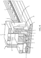
- FIG. 6 is a cross-sectional view of the carriage of the linear actuator disclosed herein, the cross section taken along a pair of apertures for screws 23 , as shown in FIG. 1A .
- the performance of many devices that rely on linear motion can be significantly improved by using a linear actuator apparatus that is driven by a rotary piezoelectric drive motor.
- a linear actuator apparatus that is driven by a rotary piezoelectric drive motor.
- Use of an electromagnetic motor in linear actuators require a separate electromagnetic motor to serve as a brake as the electromagnetic motor does not have any holding torque when de-energized.
- the piezoelectric motor eliminates the use of second motor as it provides full holding torque/force when de-energized.
- a piezoelectric rotary motor in linear actuator eliminates use of a reducer, due to the high torque of the piezoelectric motor.
- the kinematic mechanism for moving an object in a linear manner which converts rotary into linear movement, can be complicated, including either cords and converting blocks or racks. Such complicated elements can decrease the reliability of, and increase the size, weight, and cost of a device or system. Furthermore, these complicated elements limit the range of movement of the system. Moreover, the use of an additional kinematic mechanism can decrease the precision of positioning systems based on this principle.
- the disclosed technology addresses the above-mentioned problems of using an electromagnetic motor or rotary piezoelectric motor or a conventional piezoelectric motor for linear movement by using a novel piezoelectric linear actuator to move (e.g., drive or direct) an object (e.g., a blind, 3D printer head or any other suitable object).
- the disclosed technology can simplify the motorized mechanism for effectuating linear motion of an object through elimination of the kinematic connection between the motor and the object. Accordingly, reliability of operation of the linear actuator is increased, while the size, weight, and price, of the linear actuator are decreased.
- the range of movement of the linear actuator may be increased.
- the positioning resolution of the linear actuator is improved, thereby resulting in a widening of the application range.
- the disclosed technology includes the benefits and advantages that are achievable by direct coupling of the linear piezoelectric actuator to an object, thereby not requiring any additional mechanism between the linear piezoelectric actuator and the object (e.g., a blind or shade).
- the type of linear actuator in the disclosed technology can include a piezoelectric element mounted to a holder (e.g., a piezoelectric element holder) that is indirectly coupled to a moving element that can move along a guide (e.g., a long guide which can include one or more rails).
- the holder can be an acoustically isolated holder, into which the piezoelectric element is placed, and which can isolate the piezoelectric element from vibrations from the moving element moving along the guide.
- the moving element can be directly attached to an object to be moved, thereby reducing the use of a long kinematic connection.
- monitoring of the position of the moving element can be done using a position sensor (encoder).
- FIG. 1A is a diagram illustrating an example of a linear actuator apparatus 100 (also referred to as “linear actuator”).
- the linear actuator 100 is a long travel distance linear actuator (also referred to as a “long travel distance motor”).
- a linear actuator 100 may be included in any suitable device or mechanical system that requires linear motion. Examples of devices that may include a linear actuator in accordance with the present disclosure include, but are not limited to, a motorized blind system, a 3D printer, a disk drive, various robotic devices, and an adjustable seat of a vehicle. “Long travel distance” means linear distances up to at least six feet.
- the linear actuator 100 may include a piezoelectric element 1 , a moving element 2 , a guide 3 (“linear guide” or “rail”), a holder 4 , a base 5 , a contact site 6 , a contact plate 7 , springs 8 , electrodes 10 , a common electrode 11 , a pulse amplifier 12 , an external power supply 13 , a high frequency signal generator 14 , a push-button control 15 , a control system 16 , a current stabilization module 17 , an enclosure 19 , a first lead 20 , a second lead 21 , and a third lead 22 .
- the linear actuator 100 can be positioned or orientated parallel to the direction of movement of an object to be moved.
- the linear actuator 100 may be configured such that an object is connected to a carriage 18 .
- the carriage 18 includes the piezoelectric element 1 , the moving element 2 , the holder 4 and the enclosure 19 .
- the carriage 18 by way of excitation of the piezoelectric element 1 , moves longitudinally along the linear guide 3 , while the base 5 supporting the guide 3 and contact plate 7 remains stationary.
- the piezoelectric element 1 can be a variety of shapes, such as a rectangular flat resonator, in which two orthogonal longitudinal standing waves are excited.
- the piezoelectric element 1 can be any piezo material known to those skilled in the art.
- the piezoelectric element 1 can include the contact site 6 .
- the piezoelectric element 1 can be in the shape of a rectangular plane resonator and the contact site 6 can be located central on a surface of the piezoelectric element 1 .
- the moving element 2 is coupled to the carriage 18 via the enclosure 19 , whereby the moving element 2 effectuates movement of carriage 18 along the linear guide 3 as the piezoelectric element 1 oscillates.
- the moving element 2 is moved by excitation of the piezoelectric element 1 so must be indirectly coupled to the piezoelectric element 1 .
- the coupling must be indirect to reduce the interference of acoustic vibrations caused by the moving element 2 along the guide 3 , which can interfere with the piezoelectric element 1 and the contact between the contact site 6 and the contact plate 7 .
- the moving element 2 can be, for example, a linear slider shaped to fit over the guide 3 with bearings 60 to slide along the guide 3 . This is illustrated in FIG. 6 .
- the base 5 has a flat, planar surface to which the guide 3 and the contact plate 7 can be attached such that each is respectively coaligned.
- the base 5 is at least as long as the travel movement required for the object to be linearly moved.
- the linear guide 3 is mounted, attached, or otherwise coupled to the base 5 such that there is in complete contact of an underside of the guide 3 to the base 5 to ensure collinearity of their geometrical axes.
- the contact plate 7 is also mounted, attached or otherwise coupled to the base 5 such that it extends parallel to the guide 3 .
- the contact plate 7 can be attached with an adhesive 70 such as double-sided tape or glue.
- the contact plate 7 is a thin, solid, elastic plate.
- the flatness and parallel alignment of contact plate 7 with respect to the moving element 2 is important along the entire travel distance of the linear actuator 100 .
- a reference flat plane is selected according to which the flat surfaces of all other components are aligned.
- the base 5 of the actuator is selected as the reference flat surface.
- Guide 3 which is mounted on the base 5
- the moving element 2 which moves along the guide 3 , are in parallel alignment with the base 5 surface.
- the contact plate 7 because it is thin and elastic and mounted on the flat surface of the base 5 , is aligned parallel to the flat surface of the base 5 as well.
- the piezoelectric element 1 is housed in the holder 4 (e.g., a piezoelectric element holder).
- the holder 4 is an elastic material that elastically but tightly holds the piezoelectric element 1 .
- the piezoelectric element 1 and holder 4 are acoustically isolated from the moving element 2 . This is achieved by making the enclosure 19 of acoustically insolating materials, such as acoustically isolating plastic.
- acoustic vibrations from the piezoelectric element 1 may leak into the moving element 2 and guide 3 and cause resonance excitation of parasitic mechanical vibrations in the moving element 2 , such as the bearings or other parts, which could be fed back into the piezoelectric element 1 .
- the latter could lead to acoustic mechanical micro-vibrations of the piezoelectric element 1 , which decreases substantially the efficiency of the actuator 100 .
- acoustic vibrations from the moving element 2 may be prevented from leaking to the piezoelectric element 1 or other elements of the linear actuator 100 , which may cause resonance excitation of parasitic mechanical vibrations in the piezoelectric element 1 or other parts of the linear actuator 100 .
- the leaked vibrations could feed back to the piezoelectric element 1 .
- This scenario could cause acoustic mechanical micro-vibrations in the piezoelectric element 1 , which may decrease the efficiency of the linear actuator 100 .
- the carriage 18 is configured to minimize contact points between the moving element 2 and the enclosure 19 , as well as the enclosure 19 and the holder 4 .
- the holder 4 is positioned such that it does not contact the moving element 2 .
- one or more attachment pins 26 , 27 may be inserted vertically through respective receiving apertures in the enclosure 19 , through central axes of the respective springs 8 , and into respective et 4 ′ of the holder 4 .
- the enclosure 19 has a void space 62 (see FIG.
- the enclosure 19 is coupled to the moving element 2 with minimal contact points.
- the enclosure 19 may be minimally coupled to the moving element 2 using screws 23 that extend through the void space 62 to the moving element 2 .
- the enclosure 19 and the moving element 2 may be integrally connected to each other at minimum points of connection to effect minimum coupling.
- minimum couple or “minimum coupling” means using the least amount of contact points and the smallest contact area between two structures that will effectuate coupling of two structures.
- the piezoelectric element 1 includes a contact site 6 positioned or located on a central point of the side of the piezoelectric element 1 facing the contact plate 7 .
- the contact site 6 is in physical contact with the contact plate 7 (e.g., a metal contact plate), thus providing a frictional contact between the carriage 18 and the contact plate 7 .
- the frictional contact between the contact plate 7 and the contact site 6 of the piezoelectric element 1 should be of sufficient force to hold the carriage 18 in a stopped or stationary position, when the linear actuator 100 is in a resting state, eliminating the need for a braking mechanism, which continuously draws a current.
- the frictional contact is strong enough to maintain the object in a stationary position even when positioned in a vertical manner.
- the springs 8 effect this frictional force.
- the springs 8 are positioned between the enclosure 19 and the feet 4 ′ of the holder 4 such that the piezoelectric element 1 , and thus the contact site 6 of the piezoelectric element 1 , is spring loaded, forcing the contact site 6 against the contact plate 7 .
- the piezoelectric element 1 includes three electrodes, including the electrodes 10 that are located or positioned on one side of the piezoelectric element 1 , and a common electrode 11 that is located or positioned on the other side (see FIG. 6 ) of the piezoelectric element 1 .
- One of the electrodes 10 receives a first current from the electrical power source 13 to effectuate movement in a first direction along the linear guide, and the other of the electrodes 10 receives a second current to effectuate movement in a second direction along the linear guide that is opposite to the first direction.
- the common electrode 11 can be positioned on an opposite side of the piezoelectric element 1 from electrodes 10 , in which the piezoelectric element 1 is polarized perpendicular to flat resonator surfaces of the piezoelectric element 1 .
- the electrodes 10 can be two non-contacting sections of silver on opposing ends of a common surface of the piezoelectric element 1 , which the common electrode 11 can be a single section of silver on an opposing surface from the electrodes 10 .
- the piezoelectric element 1 can be polarized perpendicular to the flat surfaces of the electrodes 10 , 11 .
- the piezoelectric element 1 can generate a second order vibrational mode along a length L of the piezoelectric element and a first order vibrational mode across a width W of the piezoelectric element.
- the piezoelectric element 1 can have a natural second order vibrational mode along the length with frequency ⁇ 2 and a natural first order vibrational mode across the width with frequency ⁇ 1 .
- the ⁇ 1 frequency and the ⁇ 2 frequency are different and the difference between the ⁇ 1 frequency and the ⁇ 2 frequency is less than 20%.
- ⁇ 1 ⁇ 2 in order to obtain a smoother resonance curve and more efficient performance of the resonance curve (assuming that the excitation frequency resides on the right side of the resonance curve).
- the electrodes 10 , 10 , 11 may be in electric communication with the control system 16 .
- the electrodes 10 , 10 , 11 are attached or coupled (either directly or indirectly) to one or more leads (e.g., electrical connections), which can include the leads 20 , 21 and 22 .
- the leads 20 , 21 and 22 may be coupled, attached, or otherwise connected to the control system 16
- the leads 20 , 21 , 22 can be directly coupled to electrodes 10 , and common electrode 11 respectively, using a cable harness that is sufficient in length to move with the carriage 18 the length of the guide 3 .
- the linear actuator can include conducting rails 30 , 32 , 34 of conductive material.
- Rail 30 is electrically connected to a common electrode
- rails 32 , 34 are respectively connected to the electrodes 10 for movement along the guide 3 in a first direction and a second, opposite direction.
- Brushes 64 may extend from the enclosure 19 to electrically connect the electrodes 10 , 11 to the conductive rails 30 , 32 , 34 .
- a respective brush 64 for a respective conducting rail 30 , 32 , 34 may have continuous electrical contact with the respective conductive rail 30 , 32 , 34 , during actuator movement.
- Other electrical connecting means known to those skilled in the art are contemplated.
- control system 16 can include a pulse amplifier 12 , an external power supply 13 , and a high frequency signal generator 14 .
- the pulse amplifier 12 is connected to the power supply and amplifies the electric signal output by the power supply 13 to the leads.
- the high frequency signal generator 14 produces the excitation resonant frequency for the piezoelectric element 1 .
- control system 16 may further include a push-button control 15 that effectuates of direction of movement of the carriage 18 , including movement of the carriage 18 along a path corresponding to the guide 3 .
- a human operator may push or otherwise engage the push-button control 15 to effectuate movement of the carriage 18 by activating the power supply 13 , the pulse amplifier 12 , and the high frequency signal generator 14 .
- a push-button control 15 is shown, any other suitable means of activating the power supply 13 , the pulse amplifier 12 , and the high frequency signal generator 14 may be implemented in or with the control system 16 .
- a processor of the 3D printer may communicate with the control system 16 to activate the power supply 13 , the pulse amplifier 12 , and the high frequency signal generator 14 .
- the control system 16 further includes a current stabilization module 17 .
- the state of the resonance curve of the piezoelectric element 1 may vary due to the difficulty of holding mechanical tolerances.
- FIG. 1B further depicts an example working resonance curve 120 that displays a resonance curve 122 in three different states, 122 - 1 , 122 - 2 , 122 - 3 .
- the working resonance curve 120 plots a consumed current (e.g., the current flowing through the leads 20 , 21 , 22 , electrodes 10 , the common electrode 11 , and piezoelectric element 1 ), as a function of the set frequency of the signal output by the control system 16 (or the “frequency of excitation”).
- the shape of the resonance curve 122 will change depending on the conditions of the linear actuator 100 , the environment, including temperature and humidity, surrounding the linear actuator 100 , the location of the carriage 18 with respect to the linear guide 3 , or any other relevant conditions. As shown in the working resonance curve, as the carriage 18 moves along the linear guide 3 , the shape of the resonance curve 122 can change. In this particular example, the carriage 18 moves towards the distal end of the linear guide 3 , the consumed current increases as the frequency of the signal is kept constant.
- the linear actuator 100 disclosed herein is operated on the right side of a resonance curve, which as known to those skilled in the art, is bell shaped. As illustrated, the depicted working resonance curve 120 is the right side of the resonance curve.
- the frequencies of excitation for the linear actuators 100 disclosed herein are between about 70 KHz and 80 KHz, inclusive, as shown on the x-axis range from 70000 Hz to 80000 Hz.
- the intimate mechanical contact between the contact site 6 and the flat contact plate 7 may change. This may occur due to difficulty of holding mechanical tolerances of less than 1 um in order to provide consistent surface contact along the entire guide 3 and plate 7 .
- the resonance frequency curve may shift to left or right.
- the right side of the resonance frequency curve is flatter. That is why, when working at a frequency on the right side, the resonance frequency curve is subject to smaller changes during the movement of the carriage 18 and the control of the actuator 100 is more consistent
- the current stabilization module 17 is configured to correct the frequency of the signal in order to stabilize the consumed current to a programmed current (i.e., the current that the system is set to).
- the current stabilization module 17 may be configured to measure the consumed current that is flowing through the linear actuator 100 by way of the leads 20 , 21 , 22 , electrodes 10 , the common electrode 11 , and piezoelectric element 1 .
- the current stabilization module 17 compares the measured consumed current with the programmed current. Knowing the frequency of the signal being output by the control system 16 and the measured current, the current stabilization module 17 can determine whether to increase, decrease, or keep stable the frequency of the signal, such that the measured current stabilizes to a value that is substantially equal to the programmed current (e.g., within 50 milliamps).
- the current stabilization module 17 may determine that the consumed current corresponds to that of resonance curve 122 - 2 , as the excitation frequency is set at F g1 . In response to this determination, the current stabilization module 17 determines a point along the second resonance curve 122 - 2 that corresponds to the programmed current.
- the current stabilization module 17 determines that the frequency should be set to F g2 (e.g., ⁇ 72000 Hz) in order to stabilize the consumed current back to the programmed current (e.g., 1000 mA).
- F g2 e.g., ⁇ 72000 Hz
- the working resonance curve 120 for a particular linear actuator 100 may be determined empirically.
- FIG. 2 is a diagram illustrating an example of a holder 200 of a linear actuator (e.g., a piezoelectric actuator or a piezoelectric resonator) according to some implementations, of the present disclosure.
- the holder 200 depicted in FIG. 2 is configured as a solderless connection system.
- the holder 200 is configured such that it houses a conductive material (e.g., a material that allows the flow of electrical current, including metallic and non-metallic conductive materials) without soldering one or more wires to the electrodes of the piezoelectric element 210 .
- a conductive material e.g., a material that allows the flow of electrical current, including metallic and non-metallic conductive materials
- the solderless holder 200 includes a piezoelectric element 210 ; a mount 220 ; a contact site 230 ; a first crimp contact 240 ; a second crimp contact 242 ; and a conductive material 250 .
- the piezoelectric element 210 (e.g., the piezoelectric element 1 illustrated in FIG. 1A ), can be elastically held or secured in the mount 220 .
- the mount 220 can include one or more slots or apertures (which can be of any shape including circular, oval, or polygonal) that allow for the conductive material 250 (e.g., a flexible conductive material) to be held in contact against the piezoelectric element 210 .
- the piezoelectric element 210 can be held flush against the conductive material 250 .
- the mount 220 can hold, be attached to, or connected to, one or more of the first crimp contact 240 and the second crimp contact 242 .
- the mount 220 can be configured so that the conductive material 250 is compressed between the crimp contacts 240 , 242 and the piezoelectric element 210 . Accordingly, compression of the piezoelectric element 210 and the conductive material 250 can ensure that electrical contact between the piezoelectric element 210 and the conductive material 250 is maintained.
- Brushes 64 as described above, can be used to connect conductive rails 30 , 32 , 34 to the conductive material 250 , and in turn, the electrodes 10 and common electrode 11 .
- FIG. 3 is a flow diagram illustrating an example of a process 300 for operating a linear actuator in accordance with the present disclosure.
- the process 300 can include one or more methods of implementing the disclosed technology.
- the process 300 may be executed by a control system (e.g., control system 16 of FIG. 1A ), which may include one or more processors and/or specialized hardware components.
- a signal (e.g., an electrical signal) with a high excitation frequency corresponding to a resonance frequency, v, of a piezoelectric element (e.g., the piezoelectric element 1 illustrated in FIG. 1A ) is generated by a generator, which can include the high frequency signal generator 14 shown in FIG. 1A .
- the signal from the generator is amplified (e.g., the power or amplitude of the signal is increased) by an amplifier such as the pulse amplifier 12 shown in FIG. 1A .
- Amplification of the signal can include amplification up to a predetermined amplitude threshold or amplification to within a predetermined amplitude range.
- the piezoelectric element 1 in a carriage such as the carriage 18 shown in FIG. 1A , is excited.
- two independent orthogonal mechanical vibrational modes of the piezoelectric element interact with each other.
- a frequency of excitation of the piezoelectric element is in a range of 70 kHz to 80 kHz.
- the phase shift between the two vibrational modes of the piezoelectric element 1 is approximately (e.g., within a predetermined range) 90 degrees
- elliptical movement of a contact site e.g., the contact site 6 illustrated in FIG. 1A
- the excitation resonance frequency ⁇ will be in the range ⁇ 1 ⁇ 2 , where ⁇ 1 may be a frequency of a natural first order vibrational mode across a width of the piezoelectric element and ⁇ 2 may be a frequency of a natural second order vibrational mode across a length of the piezoelectric element.
- the piezoelectric element has a natural second order vibrational mode along its length of a frequency ⁇ 2 and a natural first order vibrational mode across its width of a frequency ⁇ 1 . Further, when the frequency ⁇ 1 and the frequency ⁇ 2 are not equal, the absolute difference between the frequency ⁇ 1 and the frequency ⁇ 2 is less than or equal to 20%. Furthermore, in some implementations, the frequency ⁇ 1 is set such that it is less than the frequency ⁇ 2 .
- the carriage 18 moves due to the signal from the generator applied to the electrode through the lead.
- Application of the signal to the piezoelectric element 1 can cause movement of the object.
- the piezoelectric element can be configured in such a way that due to special geometry and transverse polarization, two mutually orthogonal longitudinal standing waves are excited in the piezoelectric element.
- the superposition of the mutually orthogonal longitudinal standing waves can create elliptical nano-order movement of the contact site 6 .
- the moving element 2 moves linearly along the guide 3 , and consequently the object (e.g., a blind) that is connected, attached, or coupled to the moving element 2 .
- FIG. 4 is a flow diagram illustrating an example of a process 400 for operating a linear actuator in accordance with the present disclosure.
- the process 400 can include one or more methods of implementing the disclosed technology.
- the process 400 may be executed by the control system 16 , which may include one or more processors and/or specialized hardware components.
- Operations 410 - 450 respectively correspond to operations 310 - 350 of FIG. 3 .
- operations 410 - 450 incorporate the subject matter discussed with respect to operations 310 - 350 of FIG. 3 .
- the process 400 of FIG. 4 incorporates a feedback loop that allows the control system to stabilize the consumed current of the linear actuator.
- an electrical signal with a high excitation frequency corresponding to a resonance frequency, ⁇ , of the piezoelectric element 1 is generated by a generator, which can include the high frequency signal generator 14 shown in FIG. 1A .
- the signal from the generator is amplified (e.g., the power or amplitude of the signal is increased) by an amplifier such as the pulse amplifier 12 shown in FIG. 1A .
- the piezoelectric element 1 in the carriage 18 is excited.
- the control system 16 may excite the piezoelectric element 1 at a set excitation frequency F g .
- the phase shift between the two vibrational modes of the piezoelectric element is approximately (e.g., within a predetermined range) 90 degrees, elliptical movement of the contact site 6 occurs and the process 400 proceeds to 450 .
- the actuator moves due to the signal from the generator.
- the current stabilization module 17 measures a consumed current and compares the consumed current with a programmed current (I S ).
- the current stabilization module 17 may be configured to measure the consumed current that is flowing through the linear actuator by way of the leads, electrodes, the common electrode, and piezoelectric element. The current stabilization module compares the measured consumed current with the programmed current.
- the programmed current is a preset value that represents the desired current to be consumed by the linear actuator.
- the current stabilization module corrects the excitation frequency, F g , based on the results of the comparison and a working resonance curve (e.g., working resonance curve 150 of FIG. 1B ) that corresponds to the linear actuator.
- a working resonance curve e.g., working resonance curve 150 of FIG. 1B
- the control system will be exciting the piezoelectric element 1 at operation 440 at a set excitation frequency via the electric signal. Knowing the measured current, the set excitation frequency, and a working resonance curve, the current stabilization module can determine a corrected excitation frequency ( ⁇ F g ). Referring back to FIGS.
- the current stabilization module can select a resonance curve from a plurality of resonance curves (e.g., resonance curves 122 - 1 , 122 - 2 , 122 - 3 of FIG. 1B ) and determine a point of intersection between the selected resonance curve and the programmed current. The current stabilization module may then determine the corrected excitation frequency corresponding to the intersection point (e.g., the value on the x-axis of the intersection point). The current stabilization module may set the excitation frequency to the determined frequency value, and may output the newly determined excitation frequency to frequency signal generator, which adjusts the excitation frequency accordingly.
- a resonance curve e.g., resonance curves 122 - 1 , 122 - 2 , 122 - 3 of FIG. 1B
- the current stabilization module may then determine the corrected excitation frequency corresponding to the intersection point (e.g., the value on the x-axis of the intersection point).
- the current stabilization module may set the excitation frequency to the determined frequency value, and may output
- the process 400 of FIG. 4 may continue to loop in the manner described above for the duration while the linear actuator is in operation.
- FIG. 5 is a diagram illustrating an example of the linear actuator 100 disclosed here used with a blind.
- blind can refer to one or more “blinds” and can include any type of object (e.g., a blind or shade) that is used to cover some or all portions of another object (e.g., a window).
- the motorized blind system 500 includes the linear actuator 100 disclosed herein, and further includes a window 550 with a blind 552 .
- the linear actuator 100 can be positioned or orientated along the direction of movement of the blind 552 (e.g., a window blind), which can be used to cover and uncover the window 550 (e.g., an airplane window).
- the actuator 100 can be mounted, coupled, or attached, to the blind 552 via the carriage 18 .
- the signal e.g., the high frequency signal
- a lead 20 or 21 that is connected one of electrode 10 on the piezoelectric element 1
- the movement of the piezoelectric element 1 occurs, which in turn moves the contact point 6 , which in turn moves carriage 18 along the guide 3 in a first direction.
- the movement of the piezoelectric element 1 is reversed, which in turn moves the contact point 6 , which in turn moves carriage 18 along the guide 3 in a second direction, causing the blind to move in the opposite direction (e.g., closing when the blind 552 is in the open position or opening when the blind is in the closed position).
- the linear actuator 100 is configured to move the blind fully between an open position and a closed position and hold the blind at the open position, the closed position, any position in-between the open position and the closed position.
- the motorized blind system 500 of FIG. 5 is provided for example only.
- the motorized blind system 500 can be implemented in other suitable manners without departing from the scope of the disclosure.
- the maximum speed or force produced by the actuator can be varied by changing the shape of the contact site to, for example, a triangular, trapezoidal, or rectangular shape.
- robotic positioning systems such as 3D printers
- a 3D printer system can comprise two or three independently moving linear actuators positioned in mutually orthogonal XY or XYZ configurations, the linear actuator apparatus configured to move a tool along these X, Y or Z axes thus providing simultaneously precise and fast movement along these axes.
- a piezoelectric element 1 e.g., plane resonator, or piezoelectric resonator
- dimensions of a piezoelectric element 1 include sides measuring, as an example, 50 mm by 22 mm by 4 mm, indicate a frequency of excitation ⁇ equal to 75 kHz, a force of more than 10 N, and a speed of 0.2 m/s, on a linear guide of 26 inches, with consumed power in the order of 10 W.
- An advantage of the disclosed technology is its low operational noise and simple design. Further, the total weight of an actuator in the disclosed technology can be 270 g or less, which is approximately half the weight of other actuators that include a reducer.
- the holding force of a linear actuator in the disclosed technology (which requires no power consumption) is more than 50 N.
- This holding force allows the disclosed technology to be used in a variety of different positions including a vertical position, and in situations with external mechanical interference such as airplane vibrations.
- the resolution (minimum increment of movement) of the system can be approximately (e.g., within a predetermined range distance) 10 microns and can be improved down to 1 micron, using stepping (pulse) control.
- the advantages of the disclosed technology when compared to a traditional electromagnetic motorized blind include a lower weight, which can include a weight savings of approximately 50%; a vast travel range, which is constrained by the length of rail used; a fixed position with zero power consumption, since when the piezoelectric motor is not energized, no power is consumed, the position of the blind is held fixed (self-braked) by the self-decelerating force of the motor and the same force “locks” the drive system of the motor, thereby reducing or eliminating the need for a break; direct drive, since the disclosed technology eliminates the need for a gear-train; smooth silent motion, the piezoelectric motor provides high resolution and silent operation; reduction in the cost to produce the motorized blind.
Abstract
Description
Claims (20)
Priority Applications (1)
| Application Number | Priority Date | Filing Date | Title |
|---|---|---|---|
| US15/910,764 US10819251B2 (en) | 2017-03-02 | 2018-03-02 | Linear piezoelectric actuator on rail system |
Applications Claiming Priority (2)
| Application Number | Priority Date | Filing Date | Title |
|---|---|---|---|
| US201762466083P | 2017-03-02 | 2017-03-02 | |
| US15/910,764 US10819251B2 (en) | 2017-03-02 | 2018-03-02 | Linear piezoelectric actuator on rail system |
Publications (2)
| Publication Number | Publication Date |
|---|---|
| US20180254717A1 US20180254717A1 (en) | 2018-09-06 |
| US10819251B2 true US10819251B2 (en) | 2020-10-27 |
Family
ID=63357352
Family Applications (1)
| Application Number | Title | Priority Date | Filing Date |
|---|---|---|---|
| US15/910,764 Active 2039-07-18 US10819251B2 (en) | 2017-03-02 | 2018-03-02 | Linear piezoelectric actuator on rail system |
Country Status (3)
| Country | Link |
|---|---|
| US (1) | US10819251B2 (en) |
| EP (1) | EP3590185A4 (en) |
| WO (1) | WO2018161016A1 (en) |
Families Citing this family (6)
| Publication number | Priority date | Publication date | Assignee | Title |
|---|---|---|---|---|
| JP2018182871A (en) * | 2017-04-11 | 2018-11-15 | セイコーエプソン株式会社 | Piezoelectric drive device, electronic component conveyance device, robot, projector, and printer |
| JP7321688B2 (en) * | 2017-09-29 | 2023-08-07 | キヤノン株式会社 | Oscillating wave actuator and imaging device and stage device using the same |
| US11273729B2 (en) | 2018-06-28 | 2022-03-15 | Faurecia Automotive Seating, Llc | Variable efficiency actuator for a vehicle seat |
| FR3092454B1 (en) * | 2019-02-04 | 2022-06-10 | Cedrat Tech | SCREW NANOMETRIC DISPLACEMENT MECHANISM |
| CN110138266B (en) * | 2019-06-26 | 2020-04-14 | 西安电子科技大学 | Inchworm type piezoelectric actuator |
| CN110349889B (en) * | 2019-07-24 | 2021-08-13 | 广东工业大学 | Batch transfer device for micro chips |
Citations (18)
| Publication number | Priority date | Publication date | Assignee | Title |
|---|---|---|---|---|
| US4059081A (en) | 1975-10-07 | 1977-11-22 | Toyota Jidosha Kogyo Kabushiki Kaisha | EVAP system-provided throttle valve control unit |
| US4127097A (en) | 1976-12-15 | 1978-11-28 | Toyota Jidosha Kogyo Kabushiki Kaisha | Fuel evaporation control system |
| US4153025A (en) | 1977-12-02 | 1979-05-08 | General Motors Corporation | Fuel tank vapor flow control valve |
| US4308841A (en) | 1977-02-02 | 1982-01-05 | General Motors Corporation | Emission control system with integrated evaporative canister purge |
| US4902953A (en) | 1988-08-19 | 1990-02-20 | Kraft David W | Motorized window blind electrical actuator |
| US4944276A (en) | 1987-10-06 | 1990-07-31 | Colt Industries Inc | Purge valve for on board fuel vapor recovery systems |
| FR2765046A1 (en) | 1997-06-18 | 1998-12-24 | Somfy | Motorised drive without external connections for inaccessible enclosures |
| US6288473B1 (en) | 2000-03-31 | 2001-09-11 | Sandia Corporation | Frequency modulation drive for a piezoelectric motor |
| EP1333150A2 (en) | 2002-02-01 | 2003-08-06 | Somfy | Motorized window covering and method for controlling the position of a motorized window covering |
| EP1333706A1 (en) | 2002-02-01 | 2003-08-06 | Somfy | Motorized window covering and method for controlling a motorized window covering |
| US6979962B2 (en) * | 2004-03-16 | 2005-12-27 | Somfy Sas | Internally suspended motor for powered window covering |
| US7002310B2 (en) | 2004-02-25 | 2006-02-21 | Somfy Sas | Piezo-based encoder with magnetic brake for powered window covering |
| US20070096598A1 (en) * | 2004-05-12 | 2007-05-03 | Honda Motor Co., Ltd. | Drive device for ultrasonic linear motor |
| US7389806B2 (en) | 2005-02-24 | 2008-06-24 | Lawrence Kates | Motorized window shade system |
| US20100071856A1 (en) | 2008-09-25 | 2010-03-25 | Lutron Electronics Co., Inc. | Method of Automatically Controlling a Motorized Window Treatment While Minimizing Occupant Distractions |
| US7750534B2 (en) * | 2007-01-30 | 2010-07-06 | Konica Minolta Opto, Inc. | Drive device and drive system |
| US20110278987A1 (en) * | 2010-05-11 | 2011-11-17 | Canon Kabushiki Kaisha | Vibration wave actuator |
| US20150200612A1 (en) * | 2012-06-18 | 2015-07-16 | Nikon Corporation | Vibration actuator unit, stage apparatus, and optical apparatus |
Family Cites Families (8)
| Publication number | Priority date | Publication date | Assignee | Title |
|---|---|---|---|---|
| JP3244193B2 (en) * | 1992-05-26 | 2002-01-07 | 株式会社安川電機 | Planar actuator |
| DE19639606C1 (en) * | 1996-09-26 | 1998-01-22 | Fraunhofer Ges Forschung | Gripper system for handling and fine positioning |
| JP3846781B2 (en) * | 2002-02-18 | 2006-11-15 | 株式会社日立製作所 | Linear actuator |
| US6957800B2 (en) * | 2004-02-10 | 2005-10-25 | Honeywell International, Inc. | Valve assembly having a linear motor actuator |
| WO2007063693A1 (en) | 2005-11-30 | 2007-06-07 | Thk Co., Ltd. | Wireless actuator |
| JP5929138B2 (en) * | 2011-12-06 | 2016-06-01 | セイコーエプソン株式会社 | Piezoelectric motors and robots |
| KR101297719B1 (en) * | 2012-08-30 | 2013-08-20 | (주)테라솔라 | A shade drive apparatus using planet gear system |
| JP6188366B2 (en) | 2013-03-21 | 2017-08-30 | キヤノン株式会社 | Actuator and optical equipment |
-
2018
- 2018-03-02 US US15/910,764 patent/US10819251B2/en active Active
- 2018-03-02 WO PCT/US2018/020740 patent/WO2018161016A1/en unknown
- 2018-03-02 EP EP18761638.8A patent/EP3590185A4/en not_active Withdrawn
Patent Citations (18)
| Publication number | Priority date | Publication date | Assignee | Title |
|---|---|---|---|---|
| US4059081A (en) | 1975-10-07 | 1977-11-22 | Toyota Jidosha Kogyo Kabushiki Kaisha | EVAP system-provided throttle valve control unit |
| US4127097A (en) | 1976-12-15 | 1978-11-28 | Toyota Jidosha Kogyo Kabushiki Kaisha | Fuel evaporation control system |
| US4308841A (en) | 1977-02-02 | 1982-01-05 | General Motors Corporation | Emission control system with integrated evaporative canister purge |
| US4153025A (en) | 1977-12-02 | 1979-05-08 | General Motors Corporation | Fuel tank vapor flow control valve |
| US4944276A (en) | 1987-10-06 | 1990-07-31 | Colt Industries Inc | Purge valve for on board fuel vapor recovery systems |
| US4902953A (en) | 1988-08-19 | 1990-02-20 | Kraft David W | Motorized window blind electrical actuator |
| FR2765046A1 (en) | 1997-06-18 | 1998-12-24 | Somfy | Motorised drive without external connections for inaccessible enclosures |
| US6288473B1 (en) | 2000-03-31 | 2001-09-11 | Sandia Corporation | Frequency modulation drive for a piezoelectric motor |
| EP1333150A2 (en) | 2002-02-01 | 2003-08-06 | Somfy | Motorized window covering and method for controlling the position of a motorized window covering |
| EP1333706A1 (en) | 2002-02-01 | 2003-08-06 | Somfy | Motorized window covering and method for controlling a motorized window covering |
| US7002310B2 (en) | 2004-02-25 | 2006-02-21 | Somfy Sas | Piezo-based encoder with magnetic brake for powered window covering |
| US6979962B2 (en) * | 2004-03-16 | 2005-12-27 | Somfy Sas | Internally suspended motor for powered window covering |
| US20070096598A1 (en) * | 2004-05-12 | 2007-05-03 | Honda Motor Co., Ltd. | Drive device for ultrasonic linear motor |
| US7389806B2 (en) | 2005-02-24 | 2008-06-24 | Lawrence Kates | Motorized window shade system |
| US7750534B2 (en) * | 2007-01-30 | 2010-07-06 | Konica Minolta Opto, Inc. | Drive device and drive system |
| US20100071856A1 (en) | 2008-09-25 | 2010-03-25 | Lutron Electronics Co., Inc. | Method of Automatically Controlling a Motorized Window Treatment While Minimizing Occupant Distractions |
| US20110278987A1 (en) * | 2010-05-11 | 2011-11-17 | Canon Kabushiki Kaisha | Vibration wave actuator |
| US20150200612A1 (en) * | 2012-06-18 | 2015-07-16 | Nikon Corporation | Vibration actuator unit, stage apparatus, and optical apparatus |
Also Published As
| Publication number | Publication date |
|---|---|
| WO2018161016A1 (en) | 2018-09-07 |
| US20180254717A1 (en) | 2018-09-06 |
| EP3590185A1 (en) | 2020-01-08 |
| EP3590185A4 (en) | 2020-12-23 |
Similar Documents
| Publication | Publication Date | Title |
|---|---|---|
| US10819251B2 (en) | Linear piezoelectric actuator on rail system | |
| US7737605B2 (en) | Linear ultrasound motor | |
| US7508114B2 (en) | Ultrasonic motor | |
| US20030201695A1 (en) | Ultrasonic linear motor | |
| US8290724B2 (en) | Method and apparatus for controlling diaphragm displacement in synthetic jet actuators | |
| JP2006217716A (en) | Ultrasonic actuator driving unit and ultrasonic actuator driving method | |
| CN109407308B (en) | Scanning actuator and optical fiber scanner | |
| US7589454B2 (en) | Driving apparatus | |
| US20010011860A1 (en) | Piezoelectric motor | |
| US7449814B2 (en) | Driving method for ultrasonic motor and apparatus using the same | |
| CN108667341B (en) | Vibration wave motor and optical device | |
| US20210384810A1 (en) | Linear vibration motor and linear vibration system | |
| US7545076B1 (en) | System and method for tracking drive frequency of piezoelectric motor | |
| JPWO2008120454A1 (en) | Control device for vibration actuator | |
| US10468581B2 (en) | Method and apparatus for driving piezo actuator | |
| JP2011254587A (en) | Vibration type drive unit | |
| JP2007124840A (en) | Piezoelectric actuator | |
| JP3334450B2 (en) | Piezoelectric actuator and pyroelectric infrared sensor using the same | |
| JP2015053766A (en) | Linear drive unit using ultrasonic motor | |
| JP2006271169A (en) | Ultrasonic motor | |
| JP2006304425A (en) | Operation method of ultrasonic motor | |
| JPH11299269A (en) | Linear actuator | |
| JP4776884B2 (en) | Piezoelectric parts feeder | |
| JPH03253274A (en) | Ultrasonic motor | |
| JP2006271168A (en) | Ultrasonic driver and drive stage |
Legal Events
| Date | Code | Title | Description |
|---|---|---|---|
| AS | Assignment |
Owner name: DISCOVERY TECHNOLOGY INTERNATIONAL, INC., FLORIDA Free format text: ASSIGNMENT OF ASSIGNORS INTEREST;ASSIGNORS:ZHELYASKOV, VALENTIN;PETRENKO, SERHIY;BRODERICK, MARK;REEL/FRAME:045519/0071 Effective date: 20180301 |
|
| FEPP | Fee payment procedure |
Free format text: ENTITY STATUS SET TO UNDISCOUNTED (ORIGINAL EVENT CODE: BIG.); ENTITY STATUS OF PATENT OWNER: SMALL ENTITY |
|
| FEPP | Fee payment procedure |
Free format text: ENTITY STATUS SET TO SMALL (ORIGINAL EVENT CODE: SMAL); ENTITY STATUS OF PATENT OWNER: SMALL ENTITY |
|
| STPP | Information on status: patent application and granting procedure in general |
Free format text: DOCKETED NEW CASE - READY FOR EXAMINATION |
|
| AS | Assignment |
Owner name: DTI MOTION CORP., FLORIDA Free format text: SECURITY INTEREST;ASSIGNOR:DISCOVERY TECHNOLOGY INTERNATIONAL, INC.;REEL/FRAME:052353/0476 Effective date: 20200327 |
|
| AS | Assignment |
Owner name: DTI MOTION CORP., FLORIDA Free format text: ASSIGNMENT OF ASSIGNORS INTEREST;ASSIGNOR:DISCOVERY TECHNOLOGY INTERNATIONAL, INC.;REEL/FRAME:053303/0801 Effective date: 20200715 |
|
| STPP | Information on status: patent application and granting procedure in general |
Free format text: NOTICE OF ALLOWANCE MAILED -- APPLICATION RECEIVED IN OFFICE OF PUBLICATIONS |
|
| STCF | Information on status: patent grant |
Free format text: PATENTED CASE |
|
| AS | Assignment |
Owner name: PIEZO MOTION CORP., FLORIDA Free format text: CHANGE OF NAME;ASSIGNOR:DTI MOTION CORP.;REEL/FRAME:063627/0076 Effective date: 20200127 |
|
| AS | Assignment |
Owner name: BIGGER CAPITAL FUND, L.P., NEVADA Free format text: SECURITY INTEREST;ASSIGNOR:PIEZO MOTION CORP.;REEL/FRAME:063767/0644 Effective date: 20230518 |