US10814859B2 - Hybrid electric vehicle and method of controlling shift thereof - Google Patents
Hybrid electric vehicle and method of controlling shift thereof Download PDFInfo
- Publication number
- US10814859B2 US10814859B2 US16/203,029 US201816203029A US10814859B2 US 10814859 B2 US10814859 B2 US 10814859B2 US 201816203029 A US201816203029 A US 201816203029A US 10814859 B2 US10814859 B2 US 10814859B2
- Authority
- US
- United States
- Prior art keywords
- motor
- intervention
- torque
- shift
- predicted
- Prior art date
- Legal status (The legal status is an assumption and is not a legal conclusion. Google has not performed a legal analysis and makes no representation as to the accuracy of the status listed.)
- Active, expires
Links
- 238000000034 method Methods 0.000 title claims abstract description 66
- 230000005540 biological transmission Effects 0.000 claims abstract description 59
- 230000032683 aging Effects 0.000 claims description 5
- 238000004458 analytical method Methods 0.000 claims description 3
- 239000000446 fuel Substances 0.000 abstract description 15
- 230000008569 process Effects 0.000 description 25
- 239000007858 starting material Substances 0.000 description 8
- 230000006870 function Effects 0.000 description 7
- 230000009467 reduction Effects 0.000 description 6
- 241000156302 Porcine hemagglutinating encephalomyelitis virus Species 0.000 description 5
- 238000002485 combustion reaction Methods 0.000 description 5
- 230000008859 change Effects 0.000 description 4
- 238000010248 power generation Methods 0.000 description 4
- 238000006243 chemical reaction Methods 0.000 description 3
- 238000010586 diagram Methods 0.000 description 2
- 239000012530 fluid Substances 0.000 description 2
- 238000002347 injection Methods 0.000 description 2
- 239000007924 injection Substances 0.000 description 2
- 230000004048 modification Effects 0.000 description 2
- 238000012986 modification Methods 0.000 description 2
- 230000004044 response Effects 0.000 description 2
- 230000004043 responsiveness Effects 0.000 description 2
- 230000007704 transition Effects 0.000 description 2
- XUIMIQQOPSSXEZ-UHFFFAOYSA-N Silicon Chemical compound [Si] XUIMIQQOPSSXEZ-UHFFFAOYSA-N 0.000 description 1
- 230000001133 acceleration Effects 0.000 description 1
- 230000033228 biological regulation Effects 0.000 description 1
- 238000004364 calculation method Methods 0.000 description 1
- 238000004891 communication Methods 0.000 description 1
- 238000013500 data storage Methods 0.000 description 1
- 230000007423 decrease Effects 0.000 description 1
- 230000003247 decreasing effect Effects 0.000 description 1
- 230000003111 delayed effect Effects 0.000 description 1
- 230000009977 dual effect Effects 0.000 description 1
- XDDAORKBJWWYJS-UHFFFAOYSA-N glyphosate Chemical compound OC(=O)CNCP(O)(O)=O XDDAORKBJWWYJS-UHFFFAOYSA-N 0.000 description 1
- 230000006872 improvement Effects 0.000 description 1
- 238000007726 management method Methods 0.000 description 1
- 230000003287 optical effect Effects 0.000 description 1
- 230000008447 perception Effects 0.000 description 1
- 238000011084 recovery Methods 0.000 description 1
- 230000001172 regenerating effect Effects 0.000 description 1
- 230000008929 regeneration Effects 0.000 description 1
- 238000011069 regeneration method Methods 0.000 description 1
- 230000002787 reinforcement Effects 0.000 description 1
- 229910052710 silicon Inorganic materials 0.000 description 1
- 239000010703 silicon Substances 0.000 description 1
- 239000007787 solid Substances 0.000 description 1
Images


Classifications
-
- B—PERFORMING OPERATIONS; TRANSPORTING
- B60—VEHICLES IN GENERAL
- B60K—ARRANGEMENT OR MOUNTING OF PROPULSION UNITS OR OF TRANSMISSIONS IN VEHICLES; ARRANGEMENT OR MOUNTING OF PLURAL DIVERSE PRIME-MOVERS IN VEHICLES; AUXILIARY DRIVES FOR VEHICLES; INSTRUMENTATION OR DASHBOARDS FOR VEHICLES; ARRANGEMENTS IN CONNECTION WITH COOLING, AIR INTAKE, GAS EXHAUST OR FUEL SUPPLY OF PROPULSION UNITS IN VEHICLES
- B60K6/00—Arrangement or mounting of plural diverse prime-movers for mutual or common propulsion, e.g. hybrid propulsion systems comprising electric motors and internal combustion engines ; Control systems therefor, i.e. systems controlling two or more prime movers, or controlling one of these prime movers and any of the transmission, drive or drive units Informative references: mechanical gearings with secondary electric drive F16H3/72; arrangements for handling mechanical energy structurally associated with the dynamo-electric machine H02K7/00; machines comprising structurally interrelated motor and generator parts H02K51/00; dynamo-electric machines not otherwise provided for in H02K see H02K99/00
- B60K6/20—Arrangement or mounting of plural diverse prime-movers for mutual or common propulsion, e.g. hybrid propulsion systems comprising electric motors and internal combustion engines ; Control systems therefor, i.e. systems controlling two or more prime movers, or controlling one of these prime movers and any of the transmission, drive or drive units Informative references: mechanical gearings with secondary electric drive F16H3/72; arrangements for handling mechanical energy structurally associated with the dynamo-electric machine H02K7/00; machines comprising structurally interrelated motor and generator parts H02K51/00; dynamo-electric machines not otherwise provided for in H02K see H02K99/00 the prime-movers consisting of electric motors and internal combustion engines, e.g. HEVs
- B60K6/42—Arrangement or mounting of plural diverse prime-movers for mutual or common propulsion, e.g. hybrid propulsion systems comprising electric motors and internal combustion engines ; Control systems therefor, i.e. systems controlling two or more prime movers, or controlling one of these prime movers and any of the transmission, drive or drive units Informative references: mechanical gearings with secondary electric drive F16H3/72; arrangements for handling mechanical energy structurally associated with the dynamo-electric machine H02K7/00; machines comprising structurally interrelated motor and generator parts H02K51/00; dynamo-electric machines not otherwise provided for in H02K see H02K99/00 the prime-movers consisting of electric motors and internal combustion engines, e.g. HEVs characterised by the architecture of the hybrid electric vehicle
- B60K6/44—Series-parallel type
- B60K6/448—Electrical distribution type
-
- B—PERFORMING OPERATIONS; TRANSPORTING
- B60—VEHICLES IN GENERAL
- B60W—CONJOINT CONTROL OF VEHICLE SUB-UNITS OF DIFFERENT TYPE OR DIFFERENT FUNCTION; CONTROL SYSTEMS SPECIALLY ADAPTED FOR HYBRID VEHICLES; ROAD VEHICLE DRIVE CONTROL SYSTEMS FOR PURPOSES NOT RELATED TO THE CONTROL OF A PARTICULAR SUB-UNIT
- B60W10/00—Conjoint control of vehicle sub-units of different type or different function
- B60W10/10—Conjoint control of vehicle sub-units of different type or different function including control of change-speed gearings
-
- B—PERFORMING OPERATIONS; TRANSPORTING
- B60—VEHICLES IN GENERAL
- B60K—ARRANGEMENT OR MOUNTING OF PROPULSION UNITS OR OF TRANSMISSIONS IN VEHICLES; ARRANGEMENT OR MOUNTING OF PLURAL DIVERSE PRIME-MOVERS IN VEHICLES; AUXILIARY DRIVES FOR VEHICLES; INSTRUMENTATION OR DASHBOARDS FOR VEHICLES; ARRANGEMENTS IN CONNECTION WITH COOLING, AIR INTAKE, GAS EXHAUST OR FUEL SUPPLY OF PROPULSION UNITS IN VEHICLES
- B60K26/00—Arrangements or mounting of propulsion unit control devices in vehicles
- B60K26/02—Arrangements or mounting of propulsion unit control devices in vehicles of initiating means or elements
- B60K26/021—Arrangements or mounting of propulsion unit control devices in vehicles of initiating means or elements with means for providing feel, e.g. by changing pedal force characteristics
-
- B—PERFORMING OPERATIONS; TRANSPORTING
- B60—VEHICLES IN GENERAL
- B60W—CONJOINT CONTROL OF VEHICLE SUB-UNITS OF DIFFERENT TYPE OR DIFFERENT FUNCTION; CONTROL SYSTEMS SPECIALLY ADAPTED FOR HYBRID VEHICLES; ROAD VEHICLE DRIVE CONTROL SYSTEMS FOR PURPOSES NOT RELATED TO THE CONTROL OF A PARTICULAR SUB-UNIT
- B60W10/00—Conjoint control of vehicle sub-units of different type or different function
- B60W10/04—Conjoint control of vehicle sub-units of different type or different function including control of propulsion units
- B60W10/08—Conjoint control of vehicle sub-units of different type or different function including control of propulsion units including control of electric propulsion units, e.g. motors or generators
-
- B—PERFORMING OPERATIONS; TRANSPORTING
- B60—VEHICLES IN GENERAL
- B60W—CONJOINT CONTROL OF VEHICLE SUB-UNITS OF DIFFERENT TYPE OR DIFFERENT FUNCTION; CONTROL SYSTEMS SPECIALLY ADAPTED FOR HYBRID VEHICLES; ROAD VEHICLE DRIVE CONTROL SYSTEMS FOR PURPOSES NOT RELATED TO THE CONTROL OF A PARTICULAR SUB-UNIT
- B60W20/00—Control systems specially adapted for hybrid vehicles
- B60W20/20—Control strategies involving selection of hybrid configuration, e.g. selection between series or parallel configuration
-
- B—PERFORMING OPERATIONS; TRANSPORTING
- B60—VEHICLES IN GENERAL
- B60W—CONJOINT CONTROL OF VEHICLE SUB-UNITS OF DIFFERENT TYPE OR DIFFERENT FUNCTION; CONTROL SYSTEMS SPECIALLY ADAPTED FOR HYBRID VEHICLES; ROAD VEHICLE DRIVE CONTROL SYSTEMS FOR PURPOSES NOT RELATED TO THE CONTROL OF A PARTICULAR SUB-UNIT
- B60W30/00—Purposes of road vehicle drive control systems not related to the control of a particular sub-unit, e.g. of systems using conjoint control of vehicle sub-units
- B60W30/18—Propelling the vehicle
- B60W30/19—Improvement of gear change, e.g. by synchronisation or smoothing gear shift
-
- B—PERFORMING OPERATIONS; TRANSPORTING
- B60—VEHICLES IN GENERAL
- B60W—CONJOINT CONTROL OF VEHICLE SUB-UNITS OF DIFFERENT TYPE OR DIFFERENT FUNCTION; CONTROL SYSTEMS SPECIALLY ADAPTED FOR HYBRID VEHICLES; ROAD VEHICLE DRIVE CONTROL SYSTEMS FOR PURPOSES NOT RELATED TO THE CONTROL OF A PARTICULAR SUB-UNIT
- B60W50/00—Details of control systems for road vehicle drive control not related to the control of a particular sub-unit, e.g. process diagnostic or vehicle driver interfaces
- B60W50/0097—Predicting future conditions
-
- F—MECHANICAL ENGINEERING; LIGHTING; HEATING; WEAPONS; BLASTING
- F16—ENGINEERING ELEMENTS AND UNITS; GENERAL MEASURES FOR PRODUCING AND MAINTAINING EFFECTIVE FUNCTIONING OF MACHINES OR INSTALLATIONS; THERMAL INSULATION IN GENERAL
- F16H—GEARING
- F16H59/00—Control inputs to control units of change-speed-, or reversing-gearings for conveying rotary motion
- F16H59/36—Inputs being a function of speed
- F16H59/38—Inputs being a function of speed of gearing elements
-
- F—MECHANICAL ENGINEERING; LIGHTING; HEATING; WEAPONS; BLASTING
- F16—ENGINEERING ELEMENTS AND UNITS; GENERAL MEASURES FOR PRODUCING AND MAINTAINING EFFECTIVE FUNCTIONING OF MACHINES OR INSTALLATIONS; THERMAL INSULATION IN GENERAL
- F16H—GEARING
- F16H61/00—Control functions within control units of change-speed- or reversing-gearings for conveying rotary motion ; Control of exclusively fluid gearing, friction gearing, gearings with endless flexible members or other particular types of gearing
- F16H61/04—Smoothing ratio shift
- F16H61/0403—Synchronisation before shifting
-
- F—MECHANICAL ENGINEERING; LIGHTING; HEATING; WEAPONS; BLASTING
- F16—ENGINEERING ELEMENTS AND UNITS; GENERAL MEASURES FOR PRODUCING AND MAINTAINING EFFECTIVE FUNCTIONING OF MACHINES OR INSTALLATIONS; THERMAL INSULATION IN GENERAL
- F16H—GEARING
- F16H63/00—Control outputs from the control unit to change-speed- or reversing-gearings for conveying rotary motion or to other devices than the final output mechanism
- F16H63/40—Control outputs from the control unit to change-speed- or reversing-gearings for conveying rotary motion or to other devices than the final output mechanism comprising signals other than signals for actuating the final output mechanisms
- F16H63/50—Signals to an engine or motor
- F16H63/502—Signals to an engine or motor for smoothing gear shifts
-
- B—PERFORMING OPERATIONS; TRANSPORTING
- B60—VEHICLES IN GENERAL
- B60W—CONJOINT CONTROL OF VEHICLE SUB-UNITS OF DIFFERENT TYPE OR DIFFERENT FUNCTION; CONTROL SYSTEMS SPECIALLY ADAPTED FOR HYBRID VEHICLES; ROAD VEHICLE DRIVE CONTROL SYSTEMS FOR PURPOSES NOT RELATED TO THE CONTROL OF A PARTICULAR SUB-UNIT
- B60W2510/00—Input parameters relating to a particular sub-units
- B60W2510/06—Combustion engines, Gas turbines
- B60W2510/0657—Engine torque
-
- B—PERFORMING OPERATIONS; TRANSPORTING
- B60—VEHICLES IN GENERAL
- B60W—CONJOINT CONTROL OF VEHICLE SUB-UNITS OF DIFFERENT TYPE OR DIFFERENT FUNCTION; CONTROL SYSTEMS SPECIALLY ADAPTED FOR HYBRID VEHICLES; ROAD VEHICLE DRIVE CONTROL SYSTEMS FOR PURPOSES NOT RELATED TO THE CONTROL OF A PARTICULAR SUB-UNIT
- B60W2510/00—Input parameters relating to a particular sub-units
- B60W2510/08—Electric propulsion units
- B60W2510/081—Speed
-
- B—PERFORMING OPERATIONS; TRANSPORTING
- B60—VEHICLES IN GENERAL
- B60W—CONJOINT CONTROL OF VEHICLE SUB-UNITS OF DIFFERENT TYPE OR DIFFERENT FUNCTION; CONTROL SYSTEMS SPECIALLY ADAPTED FOR HYBRID VEHICLES; ROAD VEHICLE DRIVE CONTROL SYSTEMS FOR PURPOSES NOT RELATED TO THE CONTROL OF A PARTICULAR SUB-UNIT
- B60W2510/00—Input parameters relating to a particular sub-units
- B60W2510/10—Change speed gearings
- B60W2510/1025—Input torque
-
- B—PERFORMING OPERATIONS; TRANSPORTING
- B60—VEHICLES IN GENERAL
- B60W—CONJOINT CONTROL OF VEHICLE SUB-UNITS OF DIFFERENT TYPE OR DIFFERENT FUNCTION; CONTROL SYSTEMS SPECIALLY ADAPTED FOR HYBRID VEHICLES; ROAD VEHICLE DRIVE CONTROL SYSTEMS FOR PURPOSES NOT RELATED TO THE CONTROL OF A PARTICULAR SUB-UNIT
- B60W2540/00—Input parameters relating to occupants
- B60W2540/10—Accelerator pedal position
-
- B—PERFORMING OPERATIONS; TRANSPORTING
- B60—VEHICLES IN GENERAL
- B60W—CONJOINT CONTROL OF VEHICLE SUB-UNITS OF DIFFERENT TYPE OR DIFFERENT FUNCTION; CONTROL SYSTEMS SPECIALLY ADAPTED FOR HYBRID VEHICLES; ROAD VEHICLE DRIVE CONTROL SYSTEMS FOR PURPOSES NOT RELATED TO THE CONTROL OF A PARTICULAR SUB-UNIT
- B60W2710/00—Output or target parameters relating to a particular sub-units
- B60W2710/08—Electric propulsion units
- B60W2710/083—Torque
-
- B—PERFORMING OPERATIONS; TRANSPORTING
- B60—VEHICLES IN GENERAL
- B60Y—INDEXING SCHEME RELATING TO ASPECTS CROSS-CUTTING VEHICLE TECHNOLOGY
- B60Y2200/00—Type of vehicle
- B60Y2200/90—Vehicles comprising electric prime movers
- B60Y2200/92—Hybrid vehicles
-
- F—MECHANICAL ENGINEERING; LIGHTING; HEATING; WEAPONS; BLASTING
- F16—ENGINEERING ELEMENTS AND UNITS; GENERAL MEASURES FOR PRODUCING AND MAINTAINING EFFECTIVE FUNCTIONING OF MACHINES OR INSTALLATIONS; THERMAL INSULATION IN GENERAL
- F16H—GEARING
- F16H59/00—Control inputs to control units of change-speed-, or reversing-gearings for conveying rotary motion
- F16H59/36—Inputs being a function of speed
- F16H59/38—Inputs being a function of speed of gearing elements
- F16H2059/405—Rate of change of output shaft speed or vehicle speed
-
- F—MECHANICAL ENGINEERING; LIGHTING; HEATING; WEAPONS; BLASTING
- F16—ENGINEERING ELEMENTS AND UNITS; GENERAL MEASURES FOR PRODUCING AND MAINTAINING EFFECTIVE FUNCTIONING OF MACHINES OR INSTALLATIONS; THERMAL INSULATION IN GENERAL
- F16H—GEARING
- F16H61/00—Control functions within control units of change-speed- or reversing-gearings for conveying rotary motion ; Control of exclusively fluid gearing, friction gearing, gearings with endless flexible members or other particular types of gearing
- F16H61/04—Smoothing ratio shift
- F16H61/0403—Synchronisation before shifting
- F16H2061/0422—Synchronisation before shifting by an electric machine, e.g. by accelerating or braking the input shaft
-
- Y—GENERAL TAGGING OF NEW TECHNOLOGICAL DEVELOPMENTS; GENERAL TAGGING OF CROSS-SECTIONAL TECHNOLOGIES SPANNING OVER SEVERAL SECTIONS OF THE IPC; TECHNICAL SUBJECTS COVERED BY FORMER USPC CROSS-REFERENCE ART COLLECTIONS [XRACs] AND DIGESTS
- Y02—TECHNOLOGIES OR APPLICATIONS FOR MITIGATION OR ADAPTATION AGAINST CLIMATE CHANGE
- Y02T—CLIMATE CHANGE MITIGATION TECHNOLOGIES RELATED TO TRANSPORTATION
- Y02T10/00—Road transport of goods or passengers
- Y02T10/60—Other road transportation technologies with climate change mitigation effect
- Y02T10/62—Hybrid vehicles
Definitions
- the present invention relates to a hybrid electric vehicle and a method of controlling an engine thereof.
- Hybrid electric vehicles/plug-in hybrid electric vehicles are provided as a realistic alternative.
- Such a hybrid electric vehicle may provide optimum output and torque according to how two power sources, i.e., an engine and a motor, are harmoniously operated during a process of driving the hybrid electric vehicle using the engine and the motor.
- two power sources i.e., an engine and a motor
- TMED Transmission Mounted Electric Device
- EC engine clutch
- FIG. 1 is a view illustrating one example of a powertrain structure of a general hybrid electric vehicle.
- FIG. 1 illustrates a powertrain of a hybrid electric vehicle employing a parallel type hybrid system in which an electric motor (or a driving motor) 140 and an engine clutch 130 are mounted between an internal combustion engine (ICE) 110 and a transmission 150 .
- ICE internal combustion engine
- a driver presses an accelerator pedal after starting i.e., the accelerator pedal is turned on
- the motor 140 is first driven using power of a battery under the condition that the engine clutch 130 is opened, and power of the motor 140 is transmitted to wheels via the transmission 150 and a final drive (FD) 160 and thus the wheels are moved (i.e., the EV mode).
- FD final drive
- an auxiliary motor 120 is operated and may thus drive the ICE 110 .
- the engine clutch 130 is closed and thus the vehicle is driven using both the ICE 110 and the motor 140 (i.e., transition from the EV mode to the HEV mode).
- a predetermined engine off condition such as deceleration of the vehicle
- the engine clutch 130 is opened and the ICE 110 is stopped (i.e., transition from the HEV mode to the EV mode).
- the vehicle charges the battery through the motor 140 using driving power of the wheels and, such a situation is referred to as regeneration of braking energy or regenerative braking.
- the starter generator motor 120 functions as a starter motor when the ICE 110 is started and functions as a generator when rotational energy of the ICE 110 is recovered after starting or when the ICE 110 is turned off, and thus the starter generator motor 120 may be referred to as a hybrid starter generator (HSG).
- HSG hybrid starter generator
- a stepped transmission or a multiple disc clutch transmission for example, a dual clutch transmission (DCT) may be used as the automatic transmission 150 .
- the vehicle executes shift, particularly, in an upshift process, in order to effectively execute shift and protect the engine clutch 130 , the vehicle performs control of kinetic energy of an input shaft of the transmission 150 , such as reduction of torque of the driving source, i.e., deceleration, and such control may be referred to as “intervention control.”
- intervention control In a general vehicle, in order to perform intervention control, torque of an engine should be reduced and, in order to reduce the torque of the engine, air quantity control and ignition angle control may be considered.
- intervention control in order to perform intervention control, torque of an engine should be reduced and, in order to reduce the torque of the engine, air quantity control and ignition angle control may be considered.
- air quantity control means a method in which output torque is controlled by adjusting current quantity of intake air and quantity of fuel through control of an engine throttle.
- Such a control method is advantageous in that fuel efficiency may be raised through control of an optimum ignition angle corresponding to the current quantity of intake air and quantity of fuel, but has a difficulty in precise control of a quantity of intake air and a quantity of fuel which are necessary to implement request torque due to characteristics of fluid behavior and thus has a limit in responsiveness to torque change. Accordingly, this control method has excellent efficiency but needs to endure a request torque tracking error and response delay.
- ignition angle control means a method in which efficiency is sacrificed for request torque tracking.
- a quantity of air and a quantity of fuel greater than necessary quantities are first secured in cylinders of an engine (i.e., torque is reserved). If an ignition angle of an ignition plug is delayed so as to implement necessary torque at the excessive quantities of air and fuel, efficiency is lowered but torque accuracy and responsiveness may be secured.
- shift intervention control is generally implemented through ignition angle control so as to secure rapid response to engine torque reduction.
- ignition angle control is performed, as described above, the same fuel injection quantity is obtained but engine output is reduced, as compared to normal control, and thus fuel efficiency is lowered.
- engine torque is lowered by shift invention control regardless of a control method of reducing engine torque, wheel torque is also lowered and thus passengers may feel a sense of torque disconnectedness during shifting.
- reverse torque may be applied to the electric motor 140 as a driving source torque reduction means and, in this case, the electric motor 140 may perform power generation. This operation will be described with reference to FIGS. 2A to 2C .
- FIGS. 2A to 2C are graphs illustrating one example of an intervention process for upshift of a general hybrid electric vehicle.
- FIGS. 2A to 2C illustrate three graphs, and vertical axes of the graphs of FIGS. 2A to 2C respectively represent intervention, torque of an electric motor and speed of an input shaft of a transmission.
- a shift process may be generally divided into a torque phase and an inertia phase.
- the torque phase may mean a phase in which the speed of the input shaft is increased.
- the inertia phase may mean a phase in which torque of the input shaft is reduced and thus the speed of the input shaft is decreased.
- application of torque in a reverse direction, i.e., reverse torque ( ⁇ ) to the electric motor may mean power generation. Therefore, power produced through power generation of the electric motor is used to charge a battery.
- FIGS. 3A to 3C are graphs exemplarily illustrating problems generated during the intervention process in the general hybrid electric vehicle.
- a quantity of intervention which may be afforded by the electric motor is the sum of a current torque value and a reverse torque value corresponding to a charge limit and, if an intervention requirement (in FIG. 3A ) exceeds the quantity of intervention which may be afforded by the electric motor, an additional quantity of intervention may be satisfied through an engine (i.e., ignition angle delay).
- ignition angle delay may lower fuel efficiency.
- failure in predicting the quantity of intervention may also cause lowering of fuel efficiency. For example, if it is predicted that the quantity of intervention cannot be afforded by the electric motor and, thus, ignition angle delay control is performed but a quantity of intervention which is actually required can afforded by the electric motor, engine efficiency is lowered. As another example, if torque of the engine is reduced in advance but the electric motor cannot handle the overall quantity of intervention and, thus, ignition angle delay control is additionally performed, engine efficiency is also lowered.
- the present invention relates to a hybrid electric vehicle and a method of controlling an engine thereof, and particular embodiments, to a hybrid electric vehicle which may minimize fuel efficiency loss by shift intervention and a method of controlling the same.
- embodiments of the present invention are directed to a hybrid electric vehicle and a method of controlling shift thereof that substantially obviate one or more problems due to limitations and disadvantages of the related art.
- Embodiments of the present invention can provide a method of effectively performing shift intervention control in a hybrid electric vehicle, and a vehicle performing the same.
- inventions of the present invention can provide a method of controlling shift of a hybrid electric vehicle in which accuracy in prediction of a quantity of shift intervention may be raised and intervention of an engine may be minimized, and a vehicle performing the same.
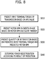
- An exemplary embodiment of the invention relates to a method of controlling shift of a hybrid electric vehicle that includes predicting torque of an input terminal of a transmission at a shift time, predicting an RPM of a motor at the shift time, predicting a quantity of intervention using the predicted torque of the input terminal of the transmission and the predicted RPM of the motor, determining whether or not intervention using the motor alone at the shift time is feasible based on the predicted quantity of intervention, and executing shift corresponding to a result of the determination.
- a hybrid electric vehicle in another aspect of the present invention, includes a first control unit configured to predict torque of an input terminal of a transmission and an RPM of a motor at a shift time, and a second control unit configured to control the transmission, to predict a quantity of intervention using the predicted torque of the input terminal of the transmission and the predicted RPM of the motor and to transmit the predicted quantity of intervention to the first control unit.
- the first control unit determines whether or not intervention using the motor alone at the shift time is feasible based on the predicted quantity of intervention and transmits a torque command corresponding to a result of the determination to a third control unit controlling the motor.
- FIG. 1 is a view illustrating one example of a powertrain structure of a general hybrid electric vehicle
- FIGS. 2A to 2C are graphs illustrating one example of an intervention process for upshift of a general hybrid electric vehicle.
- FIGS. 3A to 3C are graphs exemplarily illustrating problems generated during the intervention process in the general hybrid electric vehicle
- FIG. 4 is a block diagram illustrating one example of a control system of a hybrid electric vehicle which is applicable to one embodiment of the present invention
- FIGS. 5A to 5C are graphs illustrating one example of torque redistribution in accordance with one embodiment of the present invention.
- FIGS. 6A to 6D are graphs illustrating one example of a process of predicting a quantity of intervention in accordance with one embodiment of the present invention.
- FIGS. 7A to 7C are graphs illustrating one example of a process of performing effective shift control according to a predicted quantity of intervention in accordance with one embodiment of the present invention.
- FIG. 8 is a flowchart illustrating one example of a process of controlling shift of a hybrid electric vehicle in accordance with one embodiment of the present invention.
- FIGS. 9A to 9D are graphs illustrating one example of a process of controlling shift of a hybrid electric vehicle in accordance with another embodiment of the present invention.
- FIG. 4 Prior to description of a method of controlling shift in accordance with one embodiment of the present invention, mutual relations among powertrain control units which are applicable to the embodiment will be described with reference to FIG. 4 .
- a configuration of FIG. 4 may be applied to a hybrid electric vehicle having the above-described powertrain structure of FIG. 1 .
- FIG. 4 is a block diagram illustrating one example of a control system of a hybrid electric vehicle which is applicable to one embodiment of the present invention.
- an internal combustion engine 110 may be controlled by an engine control unit 210
- torques of a starter generator motor 120 and an electric motor 140 may be controlled by a motor control unit (MCU) 220
- an engine clutch 130 may be controlled by a clutch control unit 230
- the engine control unit 210 may be referred to as an engine management system (EMS).
- EMS engine management system
- a transmission 150 is controlled by a transmission control unit 250 .
- the starter generator motor 120 and the electric motor 140 may be respectively controlled by separate control units.
- the respective control units are connected to an upper-level control unit, i.e., a hybrid control unit (HCU) 240 which performs the entirety of a mode conversion process, and may thus provide information necessary to control the engine clutch 130 in driving mode conversion and gear shift and/or information necessary to control stoppage of the internal combustion engine 110 to the hybrid control unit 240 or perform operation according to a control signal under the control of the hybrid control unit 240 .
- HCU hybrid control unit
- the hybrid control unit 240 determines whether or not mode conversion is performed according to a driving state of the vehicle. For example, the hybrid control unit 240 determines a point in time when the engine clutch 130 is opened, and performs hydraulic pressure control (if the engine clutch 130 is a wet engine clutch) or torque capacity control (if the engine clutch 130 is a dry engine clutch) when the engine clutch 130 is opened. Further, the hybrid control unit 240 may determine a state (lock-up, slip or opening) of the engine clutch 130 and control a point in time when fuel injection of the internal combustion engine 110 is stopped.
- the hybrid control unit 240 may transmit a torque command to control torque of the starter generator motor 120 to the motor control unit 220 and thus control recovery of engine rotational energy. Moreover, the hybrid control unit 240 may calculate Distance to Empty (DTE) information according to a battery SOC by learning past driving data and employing current driving data.
- DTE Distance to Empty
- control units connection relations among the above-described control units and functions/divisions of the respective control units are exemplary and thus it will be apparent to those skilled in the art that the names of the control units are not limited.
- any one of other control units except for the hybrid control unit 240 may be implemented as having the functions of the hybrid control unit 240 , or the functions of the hybrid control unit 240 may be distributed to two or more other control units except for the hybrid control unit 240 .
- One embodiment of the present invention proposes prediction of a quantity of intervention before shift occurs and redistribution of torque to the powertrain according to a result of prediction.
- the transmission control unit 250 may predict a quantity of intervention which will be generated, using currents RPMs of an Accelerator Pedal Sensor (APS) and an input shaft of the transmission 15 o , and transmit the predicted quantity of intervention to the hybrid control unit 240 . Further, the hybrid control unit 240 may determine whether or not torque redistribution is feasible based on the predicted quantity of intervention received from the transmission control unit 250 , and, if torque redistribution is feasible, determine redistributed torque quantities and transmit corresponding torque commands to the motor control unit 220 and the engine control unit 210 .
- APS Accelerator Pedal Sensor
- Torque redistribution will be described in more detail with reference to FIGS. 5A to 5C .
- FIGS. 5A to 5C are graphs illustrating one example of torque redistribution in accordance with one embodiment of the present invention. In FIGS. 5A to 5C , it is assumed that a quantity of intervention is accurately predicted.
- torque of the electric motor may be raised in advance by a shortfall but torque of the engine may be reduced as much, in the torque phase.
- the reason for this is to reduce torque of the engine by the torque increment of the electric motor so as to maintain the overall quantity of torque.
- reduction in torque of the engine may be performed throughout the torque phase and, thus, rapid ignition angle perception is not necessary. Therefore, a method having low decline in fuel efficiency, for example, the air quantity control method, may be applied but the disclosure is not limited thereto.
- FIGS. 6A to 6D are graphs illustrating one example of a process of predicting a quantity of intervention in accordance with one embodiment of the present invention.
- FIGS. 6A to 6D illustrate four graphs P 1 to P 4 .
- the graphs P 1 to P 4 share one horizontal axis representing time, a vertical axis of the graph P 1 represents an actual quantity (requirement) of intervention, a vertical axis of the graph P 2 represents an RPM of a motor, the vertical axis of the graph P 3 represents torque of an input terminal of a transmission, and a vertical axis of the graph P 4 represents a quantity of intervention, predicted by a vehicle, respectively.
- a quantity of intervention may be determined by an RPM of the motor and torque of an input terminal of the transmission when the vehicle enters the torque phase. Therefore, prediction of the quantity of intervention may mean prediction of the RPM of the motor and the torque of the input terminal of the transmission when the vehicle enters the torque phase.
- torque of an input terminal of the transmission shown in the graph P 3 may be predicted based on the APS.
- the torque of the input terminal of the transmission when the vehicle enters the inertia phase may be calculated by equation “f(APS, t 1 )+current input terminal torque” or “f(t 1 , APS, etc)+current input terminal torque”.
- a predicted quantity A of intervention may be determined in the torque phase, as exemplarily shown in the graph P 4 .
- FIGS. 7A to 7C are graphs illustrating one example of a process of performing effective shift control according to a predicted quantity of intervention in accordance with one embodiment of the present invention.
- the process shown in FIGS. 7A to 7C is subsequent to the process shown in FIGS. 6A to 6D and, in this process, it is assumed that the predicted quantity of intervention is the same as the predicted quantity A of intervention of FIG. 6D .
- FIGS. 7A to 7C illustrate three graphs P 5 to P 7 .
- the graphs P 5 to P 7 share one horizontal axis representing time, vertical axes of the graphs P 5 and P 6 represent torque of the motor, and a vertical axis of the graph P 7 represents torque of the engine.
- “B” in the graphs P 5 and P 6 represents a quantity of intervention which may be afforded by the motor when the vehicle enters shift control, and the quantity of intervention corresponds to the sum of output torque of the motor and charge limit torque, as described above.
- the entirety of the predicted quantity A of intervention is satisfied through torque control of the motor in the inertia phase.
- a quantity of intervention may be predicted, the predicted quantity of intervention may be compared to a quantity of intervention which may be afforded by the motor, and torque redistribution is performed in the torque phase according to a result of comparison, thus preventing intervention control of the engine in the inertia phase.
- torque redistribution is performed in the torque phase according to a result of comparison, thus preventing intervention control of the engine in the inertia phase.
- when reduction in torque of the engine is necessary according to control of rise in torque of the motor if the reduced engine torque deviates from an optimum efficiency driving point of the engine by a designated level or more, such a power redistribution process may not be performed.
- FIG. 8 is a flowchart illustrating one example of a process of controlling shift of a hybrid electric vehicle in accordance with one embodiment of the present invention.
- torque of the input terminal of the transmission may be predicted based on a value of the APS according to an opening degree of the accelerator pedal pressed by a driver (Operation S 810 ), and an RPM of the motor during shifting may be predicted through an upward slope of the RPM of the motor (Operation S 820 ).
- prediction of the torque of the input terminal of the transmission may be performed by the hybrid control unit, and prediction of the RPM of the motor may be performed by the hybrid control unit or the transmission control unit.
- the predicted values of the torque of the input terminal of the transmission and the RPM of the motor may be values predicted at a point in time when the inertia phase is started, and a method of predicting the torque of the input terminal of the transmission and the RPM of the motor is the same as the above-described method in FIGS. 6A to 6D and a detailed description thereof will thus be omitted.
- the transmission control unit may predict a quantity of intervention based on the predicted RPM of the motor and the predicted torque of the input terminal of the transmission (Operation S 830 ).
- a calculation method using a predetermined function may be used or a method in which a predetermined map or lookup table is referred to may be used, but the disclosure is not limited thereto.
- the transmission control unit may transmit the predicted quantity of intervention to the hybrid control unit, and the hybrid control unit may determine whether or not intervention of the engine is avoidable by comparing the predicted quantity of intervention to a quantity of intervention which may be afforded by the motor (Operation S 840 ). According to a result of determination, the hybrid control unit may transmit a torque command to the motor control unit so that intervention is performed by the electric motor alone, or determine redistribution quantities of power so that power is redistributed in the torque phase and transmit torque commands respectively corresponding to the redistribution quantities of power to the engine control unit and the motor control unit.
- near future predicted correction to predict torque of an input terminal of the transmission and an RPM of the motor at a more accurate shift time may be introduced.
- a control process in the inertia phase is the same as that in the former embodiment shown in FIG. 8 and only a prediction process is different from that in the former embodiment. Therefore, a detailed description of parts in this embodiment which are substantially the same as those of the former embodiment will be omitted because it is considered to be unnecessary.
- information collected at the outside of the vehicle may be additionally considered.
- the information collected at the outside of the vehicle may be acquired by the vehicle via a wireless communication unit, such as a telematics module or an AVN system, from a telematics center or a separate server.
- the information collected at the outside of the vehicle may include past data of similar shift cases according to classification standards, such as kinds of shift (upshift, downshift, kick down shift, etc.), and a current vehicle driving state (speed change, request torque change, uphill/downhill driving, etc.), or correction parameters based on the past data, or be a near future predicted model function based on big data.
- classification standards such as kinds of shift (upshift, downshift, kick down shift, etc.)
- a current vehicle driving state speed change, request torque change, uphill/downhill driving, etc.
- correction parameters based on the past data or be a near future predicted model function based on big data.
- FIGS. 9A to 9D are graphs illustrating one example of a process of controlling shift of a hybrid electric vehicle in accordance with another embodiment of the present invention.
- FIGS. 9A to 9D illustrate four graphs P 1 ′ to P 4 ′.
- the respective graphs P 1 ′ to P 4 ′ share one horizontal axis representing time, a vertical axis of the graph P 1 ′ represents an actual quantity (requirement) of intervention, a vertical axis of the graph P 2 ′ represents an RPM of a motor, the vertical axis of the graph P 3 ′ represents torque of a transmission input terminal, and a vertical axis of the graph P 4 ′ represents a quantity of intervention, predicted by a vehicle, respectively. It is assumed that an actual RPM n 2 ′ of the motor and torque of the input terminal of the transmission in this embodiment are raised and thus an actual quantity of intervention in this embodiment is increased, as compared to the embodiment shown in FIGS. 6A to 6D .
- an initial quantity of intervention is calculated through the method shown in FIGS. 6A to 6D and FIG. 8 , but a final quantity of intervention is corrected through feedback by performing near future predicted correction and, thus, accuracy may be improved.
- an initial predicted RPM of the motor and an initial predicted torque of the input terminal of the transmission at a point in time when the torque phase is started are calculated by the above-described method described with reference to FIGS. 6A to 6D and, when a final quantity of intervention is predicted, external data (case data) corresponding to a current driving state of the vehicle and state information (for example, aging state information) of the transmission are additionally considered by equation ”f(predicted RPM, predicted input terminal torque)+f(shift case data, TM aging) and, thus, accuracy in prediction may be improved.
- Operation S 830 of FIG. 8 may be changed, as below.
- the transmission control unit predicts a quantity of intervention additionally using near future prediction data, instead of prediction of the quantity of intervention using only the predicted RPM of the motor and the predicted torque of the input terminal of the transmission, and transmits the predicted quantity of intervention to the hybrid control unit.
- the near future prediction data may be received in advance from an AVN system or a telematics unit, and may include at least one of deviations in vehicles or power source torque deviations acquired through analysis of conventional similar shift case data, or correction data according to transmission hydraulic characteristics/hydraulic system aging degrees.
- Computer readable recording media include all kinds of recording devices in which data readable by computer systems is stored.
- the computer readable recording media may include a Hard Disk Drive (HDD), a Solid State Drive (SSD), a Silicon Disk Drive (SDD), a ROM, a RAM, a CD-ROM, a magnetic tape, a floppy disk, an optical data storage system, etc.
- a hybrid electric vehicle in accordance with at least one embodiment of the present invention may effectively perform shift control.
- the hybrid electric vehicle more accurately predicts a quantity of intervention prior to shift, redistributes torque to an engine and a motor in advance therethrough so as to minimize involvement of the engine in shift intervention, and thus improves efficiency.
Landscapes
- Engineering & Computer Science (AREA)
- Mechanical Engineering (AREA)
- Transportation (AREA)
- General Engineering & Computer Science (AREA)
- Chemical & Material Sciences (AREA)
- Combustion & Propulsion (AREA)
- Automation & Control Theory (AREA)
- Human Computer Interaction (AREA)
- Hybrid Electric Vehicles (AREA)
- Electric Propulsion And Braking For Vehicles (AREA)
Applications Claiming Priority (2)
| Application Number | Priority Date | Filing Date | Title |
|---|---|---|---|
| KR10-2017-0167258 | 2017-12-07 | ||
| KR1020170167258A KR102444664B1 (ko) | 2017-12-07 | 2017-12-07 | 하이브리드 자동차 및 그를 위한 변속 제어 방법 |
Publications (2)
| Publication Number | Publication Date |
|---|---|
| US20190176796A1 US20190176796A1 (en) | 2019-06-13 |
| US10814859B2 true US10814859B2 (en) | 2020-10-27 |
Family
ID=66735120
Family Applications (1)
| Application Number | Title | Priority Date | Filing Date |
|---|---|---|---|
| US16/203,029 Active 2039-03-29 US10814859B2 (en) | 2017-12-07 | 2018-11-28 | Hybrid electric vehicle and method of controlling shift thereof |
Country Status (3)
| Country | Link |
|---|---|
| US (1) | US10814859B2 (ko) |
| KR (1) | KR102444664B1 (ko) |
| CN (1) | CN109895778B (ko) |
Families Citing this family (3)
| Publication number | Priority date | Publication date | Assignee | Title |
|---|---|---|---|---|
| KR102444667B1 (ko) * | 2017-12-28 | 2022-09-19 | 현대자동차주식회사 | 하이브리드 자동차 및 그를 위한 주행 모드 제어 방법 |
| CN111692331B (zh) * | 2020-06-29 | 2021-10-29 | 潍柴动力股份有限公司 | 发动机换挡的控制方法、装置以及重卡牵引车 |
| KR20230160997A (ko) | 2022-05-17 | 2023-11-27 | 현대자동차주식회사 | 하이브리드 자동차 및 그를 위한 변속 제어 방법 |
Citations (4)
| Publication number | Priority date | Publication date | Assignee | Title |
|---|---|---|---|---|
| US20080119975A1 (en) * | 2006-11-16 | 2008-05-22 | Ford Global Technologies, Llc | Hybrid Electric Vehicle Powertrain with Engine Start and Transmission Shift Arbitration |
| US20160318500A1 (en) * | 2015-04-29 | 2016-11-03 | Hyundai Motor Company | Device and Method for Controlling Torque Intervention of a Hybrid Vehicle |
| US20170144651A1 (en) * | 2015-11-19 | 2017-05-25 | Hyundai Motor Company | Method and device for controlling torque intervention of hybrid vehicle |
| US20170297554A1 (en) * | 2016-04-15 | 2017-10-19 | Hyundai Motor Company | Control method of power train for hybrid vehicle and control system for the same |
Family Cites Families (11)
| Publication number | Priority date | Publication date | Assignee | Title |
|---|---|---|---|---|
| JP2000008901A (ja) * | 1998-06-19 | 2000-01-11 | Toyota Motor Corp | 原動機と自動変速機との一体制御装置 |
| US9446757B2 (en) * | 2014-03-05 | 2016-09-20 | Ford Global Technologies, Llc | Active motor damping control of a hybrid electric vehicle powertrain |
| KR101592695B1 (ko) * | 2014-05-21 | 2016-02-15 | 현대자동차주식회사 | Dct차량의 변속 제어방법 |
| US10207696B2 (en) * | 2014-06-09 | 2019-02-19 | Ford Global Technologies, Llc | Timing transmission gearing shifts for a hybrid electric powertrain |
| KR101558811B1 (ko) * | 2014-09-24 | 2015-10-07 | 현대자동차주식회사 | 하이브리드 차량의 회생제동 중 변속 제어 방법 |
| US9944269B2 (en) * | 2015-04-14 | 2018-04-17 | Ford Global Technologies, Llc | Input torque trim for transmission shift control during regenerative braking |
| KR101673357B1 (ko) | 2015-07-07 | 2016-11-07 | 현대자동차 주식회사 | 하이브리드 차량의 토크 인터벤션 제어 시스템 및 그 방법 |
| KR101714214B1 (ko) * | 2015-09-10 | 2017-03-08 | 현대자동차주식회사 | 하이브리드 차량의 변속시 토크 인터벤션 제어 시스템 및 방법 |
| KR101713752B1 (ko) * | 2015-10-28 | 2017-03-22 | 현대자동차 주식회사 | 차량의 변속 제어 장치 및 그 방법 |
| KR101744839B1 (ko) * | 2015-11-19 | 2017-06-08 | 현대자동차주식회사 | 하이브리드 차량의 토크 인터벤션 제어 방법 및 그 제어 장치 |
| US10081364B2 (en) * | 2016-01-12 | 2018-09-25 | Ford Global Technologies, Llc | System and method for controlling a transmission gear shift |
-
2017
- 2017-12-07 KR KR1020170167258A patent/KR102444664B1/ko active IP Right Grant
-
2018
- 2018-11-28 US US16/203,029 patent/US10814859B2/en active Active
- 2018-12-07 CN CN201811497969.9A patent/CN109895778B/zh active Active
Patent Citations (4)
| Publication number | Priority date | Publication date | Assignee | Title |
|---|---|---|---|---|
| US20080119975A1 (en) * | 2006-11-16 | 2008-05-22 | Ford Global Technologies, Llc | Hybrid Electric Vehicle Powertrain with Engine Start and Transmission Shift Arbitration |
| US20160318500A1 (en) * | 2015-04-29 | 2016-11-03 | Hyundai Motor Company | Device and Method for Controlling Torque Intervention of a Hybrid Vehicle |
| US20170144651A1 (en) * | 2015-11-19 | 2017-05-25 | Hyundai Motor Company | Method and device for controlling torque intervention of hybrid vehicle |
| US20170297554A1 (en) * | 2016-04-15 | 2017-10-19 | Hyundai Motor Company | Control method of power train for hybrid vehicle and control system for the same |
Also Published As
| Publication number | Publication date |
|---|---|
| US20190176796A1 (en) | 2019-06-13 |
| CN109895778B (zh) | 2024-02-02 |
| KR20190067375A (ko) | 2019-06-17 |
| KR102444664B1 (ko) | 2022-09-19 |
| CN109895778A (zh) | 2019-06-18 |
Similar Documents
| Publication | Publication Date | Title |
|---|---|---|
| US11654879B2 (en) | System and method for controlling hybrid electric vehicle using driving tendency of driver | |
| US10768635B2 (en) | Hybrid electric vehicle and platooning control method therefor | |
| US20160375892A1 (en) | System and method for engine stop control of hybrid vehicle | |
| EP3575130A1 (en) | Vehicle control system and method of controlling the same, and braking device | |
| US10814859B2 (en) | Hybrid electric vehicle and method of controlling shift thereof | |
| US10562518B2 (en) | Apparatus and method for controlling a powertrain in a vehicle | |
| US11254303B2 (en) | Hybrid vehicle and method of controlling gear shifting for the same | |
| US10787166B2 (en) | Hybrid electric vehicle and method of controlling shift pattern therefor | |
| US10532734B2 (en) | Hybrid vehicle and method of controlling motor of the same | |
| US11926310B2 (en) | Hybrid electric vehicle and method for controlling speed limit for the same | |
| US10099685B2 (en) | Hybrid electric vehicle and method of efficiently controlling transmission thereof | |
| US11453383B2 (en) | Hybrid vehicle and method of controlling gear shift for the same | |
| US11312240B2 (en) | Hybrid electric vehicle and braking control method thereof | |
| KR102515553B1 (ko) | 하이브리드 자동차 및 그를 위한 충전 제어 방법 | |
| KR102422145B1 (ko) | 전동화 차량의 런치 컨트롤 방법 및 전동화 차량 | |
| US20230339450A1 (en) | Hybrid electric vehicle and a shift control method for same | |
| US11440419B2 (en) | Method of controlling gear shifting in electric vehicle | |
| US20230347869A1 (en) | Hybrid electric vehicle and control method thereof | |
| US20230119802A1 (en) | Hybrid electric vehicle and method of motor control for the same | |
| KR20210157514A (ko) | 하이브리드 자동차 및 그 제어 방법 | |
| KR20230160997A (ko) | 하이브리드 자동차 및 그를 위한 변속 제어 방법 | |
| KR20230158674A (ko) | 하이브리드 자동차 및 그를 위한 주행 제어 방법 |
Legal Events
| Date | Code | Title | Description |
|---|---|---|---|
| AS | Assignment |
Owner name: KIA MOTORS CORPORATION, KOREA, REPUBLIC OF Free format text: ASSIGNMENT OF ASSIGNORS INTEREST;ASSIGNORS:MOON, SEONG WOOK;PARK, JOON YOUNG;REEL/FRAME:047610/0902 Effective date: 20181108 Owner name: HYUNDAI MOTOR COMPANY, KOREA, REPUBLIC OF Free format text: ASSIGNMENT OF ASSIGNORS INTEREST;ASSIGNORS:MOON, SEONG WOOK;PARK, JOON YOUNG;REEL/FRAME:047610/0902 Effective date: 20181108 |
|
| FEPP | Fee payment procedure |
Free format text: ENTITY STATUS SET TO UNDISCOUNTED (ORIGINAL EVENT CODE: BIG.); ENTITY STATUS OF PATENT OWNER: LARGE ENTITY |
|
| STPP | Information on status: patent application and granting procedure in general |
Free format text: DOCKETED NEW CASE - READY FOR EXAMINATION |
|
| STPP | Information on status: patent application and granting procedure in general |
Free format text: NOTICE OF ALLOWANCE MAILED -- APPLICATION RECEIVED IN OFFICE OF PUBLICATIONS |
|
| STPP | Information on status: patent application and granting procedure in general |
Free format text: PUBLICATIONS -- ISSUE FEE PAYMENT VERIFIED |
|
| STCF | Information on status: patent grant |
Free format text: PATENTED CASE |
|
| CC | Certificate of correction | ||
| MAFP | Maintenance fee payment |
Free format text: PAYMENT OF MAINTENANCE FEE, 4TH YEAR, LARGE ENTITY (ORIGINAL EVENT CODE: M1551); ENTITY STATUS OF PATENT OWNER: LARGE ENTITY Year of fee payment: 4 |