US10788036B2 - Peristaltic pump - Google Patents
Peristaltic pump Download PDFInfo
- Publication number
- US10788036B2 US10788036B2 US15/535,562 US201615535562A US10788036B2 US 10788036 B2 US10788036 B2 US 10788036B2 US 201615535562 A US201615535562 A US 201615535562A US 10788036 B2 US10788036 B2 US 10788036B2
- Authority
- US
- United States
- Prior art keywords
- housing
- printed circuit
- peristaltic pump
- circuit board
- head
- Prior art date
- Legal status (The legal status is an assumption and is not a legal conclusion. Google has not performed a legal analysis and makes no representation as to the accuracy of the status listed.)
- Active, expires
Links
- 230000002572 peristaltic effect Effects 0.000 title claims abstract description 90
- NFLLKCVHYJRNRH-UHFFFAOYSA-N 8-chloro-1,3-dimethyl-7H-purine-2,6-dione 2-(diphenylmethyl)oxy-N,N-dimethylethanamine Chemical compound O=C1N(C)C(=O)N(C)C2=C1NC(Cl)=N2.C=1C=CC=CC=1C(OCCN(C)C)C1=CC=CC=C1 NFLLKCVHYJRNRH-UHFFFAOYSA-N 0.000 claims description 8
- 230000008878 coupling Effects 0.000 description 7
- 238000010168 coupling process Methods 0.000 description 7
- 238000005859 coupling reaction Methods 0.000 description 7
- 238000009434 installation Methods 0.000 description 4
- 238000012423 maintenance Methods 0.000 description 4
- 229920003023 plastic Polymers 0.000 description 4
- 239000004033 plastic Substances 0.000 description 4
- 239000012530 fluid Substances 0.000 description 2
- 239000006260 foam Substances 0.000 description 2
- 230000001681 protective effect Effects 0.000 description 2
- 239000000126 substance Substances 0.000 description 2
- XLYOFNOQVPJJNP-UHFFFAOYSA-N water Substances O XLYOFNOQVPJJNP-UHFFFAOYSA-N 0.000 description 2
- 235000013361 beverage Nutrition 0.000 description 1
- 238000004140 cleaning Methods 0.000 description 1
- 239000000645 desinfectant Substances 0.000 description 1
- 238000003780 insertion Methods 0.000 description 1
- 230000037431 insertion Effects 0.000 description 1
- 238000004519 manufacturing process Methods 0.000 description 1
- 239000000203 mixture Substances 0.000 description 1
- 239000000344 soap Substances 0.000 description 1
- 238000004659 sterilization and disinfection Methods 0.000 description 1
- 235000020357 syrup Nutrition 0.000 description 1
- 239000006188 syrup Substances 0.000 description 1
Images


Classifications
-
- F—MECHANICAL ENGINEERING; LIGHTING; HEATING; WEAPONS; BLASTING
- F04—POSITIVE - DISPLACEMENT MACHINES FOR LIQUIDS; PUMPS FOR LIQUIDS OR ELASTIC FLUIDS
- F04B—POSITIVE-DISPLACEMENT MACHINES FOR LIQUIDS; PUMPS
- F04B43/00—Machines, pumps, or pumping installations having flexible working members
- F04B43/12—Machines, pumps, or pumping installations having flexible working members having peristaltic action
- F04B43/1253—Machines, pumps, or pumping installations having flexible working members having peristaltic action by using two or more rollers as squeezing elements, the rollers moving on an arc of a circle during squeezing
-
- F—MECHANICAL ENGINEERING; LIGHTING; HEATING; WEAPONS; BLASTING
- F04—POSITIVE - DISPLACEMENT MACHINES FOR LIQUIDS; PUMPS FOR LIQUIDS OR ELASTIC FLUIDS
- F04B—POSITIVE-DISPLACEMENT MACHINES FOR LIQUIDS; PUMPS
- F04B49/00—Control, e.g. of pump delivery, or pump pressure of, or safety measures for, machines, pumps, or pumping installations, not otherwise provided for, or of interest apart from, groups F04B1/00 - F04B47/00
- F04B49/06—Control using electricity
- F04B49/065—Control using electricity and making use of computers
-
- F—MECHANICAL ENGINEERING; LIGHTING; HEATING; WEAPONS; BLASTING
- F04—POSITIVE - DISPLACEMENT MACHINES FOR LIQUIDS; PUMPS FOR LIQUIDS OR ELASTIC FLUIDS
- F04B—POSITIVE-DISPLACEMENT MACHINES FOR LIQUIDS; PUMPS
- F04B49/00—Control, e.g. of pump delivery, or pump pressure of, or safety measures for, machines, pumps, or pumping installations, not otherwise provided for, or of interest apart from, groups F04B1/00 - F04B47/00
- F04B49/20—Control, e.g. of pump delivery, or pump pressure of, or safety measures for, machines, pumps, or pumping installations, not otherwise provided for, or of interest apart from, groups F04B1/00 - F04B47/00 by changing the driving speed
-
- F—MECHANICAL ENGINEERING; LIGHTING; HEATING; WEAPONS; BLASTING
- F04—POSITIVE - DISPLACEMENT MACHINES FOR LIQUIDS; PUMPS FOR LIQUIDS OR ELASTIC FLUIDS
- F04B—POSITIVE-DISPLACEMENT MACHINES FOR LIQUIDS; PUMPS
- F04B53/00—Component parts, details or accessories not provided for in, or of interest apart from, groups F04B1/00 - F04B23/00 or F04B39/00 - F04B47/00
- F04B53/22—Arrangements for enabling ready assembly or disassembly
-
- H—ELECTRICITY
- H01—ELECTRIC ELEMENTS
- H01R—ELECTRICALLY-CONDUCTIVE CONNECTIONS; STRUCTURAL ASSOCIATIONS OF A PLURALITY OF MUTUALLY-INSULATED ELECTRICAL CONNECTING ELEMENTS; COUPLING DEVICES; CURRENT COLLECTORS
- H01R12/00—Structural associations of a plurality of mutually-insulated electrical connecting elements, specially adapted for printed circuits, e.g. printed circuit boards [PCB], flat or ribbon cables, or like generally planar structures, e.g. terminal strips, terminal blocks; Coupling devices specially adapted for printed circuits, flat or ribbon cables, or like generally planar structures; Terminals specially adapted for contact with, or insertion into, printed circuits, flat or ribbon cables, or like generally planar structures
- H01R12/70—Coupling devices
- H01R12/71—Coupling devices for rigid printing circuits or like structures
- H01R12/712—Coupling devices for rigid printing circuits or like structures co-operating with the surface of the printed circuit or with a coupling device exclusively provided on the surface of the printed circuit
- H01R12/716—Coupling device provided on the PCB
- H01R12/718—Contact members provided on the PCB without an insulating housing
-
- H—ELECTRICITY
- H02—GENERATION; CONVERSION OR DISTRIBUTION OF ELECTRIC POWER
- H02K—DYNAMO-ELECTRIC MACHINES
- H02K11/00—Structural association of dynamo-electric machines with electric components or with devices for shielding, monitoring or protection
- H02K11/30—Structural association with control circuits or drive circuits
- H02K11/33—Drive circuits, e.g. power electronics
-
- H—ELECTRICITY
- H02—GENERATION; CONVERSION OR DISTRIBUTION OF ELECTRIC POWER
- H02K—DYNAMO-ELECTRIC MACHINES
- H02K7/00—Arrangements for handling mechanical energy structurally associated with dynamo-electric machines, e.g. structural association with mechanical driving motors or auxiliary dynamo-electric machines
- H02K7/10—Structural association with clutches, brakes, gears, pulleys or mechanical starters
- H02K7/116—Structural association with clutches, brakes, gears, pulleys or mechanical starters with gears
-
- H—ELECTRICITY
- H05—ELECTRIC TECHNIQUES NOT OTHERWISE PROVIDED FOR
- H05K—PRINTED CIRCUITS; CASINGS OR CONSTRUCTIONAL DETAILS OF ELECTRIC APPARATUS; MANUFACTURE OF ASSEMBLAGES OF ELECTRICAL COMPONENTS
- H05K1/00—Printed circuits
- H05K1/02—Details
- H05K1/11—Printed elements for providing electric connections to or between printed circuits
-
- H—ELECTRICITY
- H05—ELECTRIC TECHNIQUES NOT OTHERWISE PROVIDED FOR
- H05K—PRINTED CIRCUITS; CASINGS OR CONSTRUCTIONAL DETAILS OF ELECTRIC APPARATUS; MANUFACTURE OF ASSEMBLAGES OF ELECTRICAL COMPONENTS
- H05K5/00—Casings, cabinets or drawers for electric apparatus
- H05K5/0026—Casings, cabinets or drawers for electric apparatus provided with connectors and printed circuit boards [PCB], e.g. automotive electronic control units
- H05K5/0047—Casings, cabinets or drawers for electric apparatus provided with connectors and printed circuit boards [PCB], e.g. automotive electronic control units having a two-part housing enclosing a PCB
- H05K5/006—Casings, cabinets or drawers for electric apparatus provided with connectors and printed circuit boards [PCB], e.g. automotive electronic control units having a two-part housing enclosing a PCB characterized by features for holding the PCB within the housing
-
- H—ELECTRICITY
- H05—ELECTRIC TECHNIQUES NOT OTHERWISE PROVIDED FOR
- H05K—PRINTED CIRCUITS; CASINGS OR CONSTRUCTIONAL DETAILS OF ELECTRIC APPARATUS; MANUFACTURE OF ASSEMBLAGES OF ELECTRICAL COMPONENTS
- H05K1/00—Printed circuits
- H05K1/18—Printed circuits structurally associated with non-printed electric components
- H05K1/181—Printed circuits structurally associated with non-printed electric components associated with surface mounted components
-
- H—ELECTRICITY
- H05—ELECTRIC TECHNIQUES NOT OTHERWISE PROVIDED FOR
- H05K—PRINTED CIRCUITS; CASINGS OR CONSTRUCTIONAL DETAILS OF ELECTRIC APPARATUS; MANUFACTURE OF ASSEMBLAGES OF ELECTRICAL COMPONENTS
- H05K2201/00—Indexing scheme relating to printed circuits covered by H05K1/00
- H05K2201/09—Shape and layout
- H05K2201/09009—Substrate related
- H05K2201/09027—Non-rectangular flat PCB, e.g. circular
-
- H—ELECTRICITY
- H05—ELECTRIC TECHNIQUES NOT OTHERWISE PROVIDED FOR
- H05K—PRINTED CIRCUITS; CASINGS OR CONSTRUCTIONAL DETAILS OF ELECTRIC APPARATUS; MANUFACTURE OF ASSEMBLAGES OF ELECTRICAL COMPONENTS
- H05K2201/00—Indexing scheme relating to printed circuits covered by H05K1/00
- H05K2201/10—Details of components or other objects attached to or integrated in a printed circuit board
- H05K2201/10007—Types of components
- H05K2201/1009—Electromotor
-
- H—ELECTRICITY
- H05—ELECTRIC TECHNIQUES NOT OTHERWISE PROVIDED FOR
- H05K—PRINTED CIRCUITS; CASINGS OR CONSTRUCTIONAL DETAILS OF ELECTRIC APPARATUS; MANUFACTURE OF ASSEMBLAGES OF ELECTRICAL COMPONENTS
- H05K3/00—Apparatus or processes for manufacturing printed circuits
- H05K3/30—Assembling printed circuits with electric components, e.g. with resistor
- H05K3/32—Assembling printed circuits with electric components, e.g. with resistor electrically connecting electric components or wires to printed circuits
- H05K3/325—Assembling printed circuits with electric components, e.g. with resistor electrically connecting electric components or wires to printed circuits by abutting or pinching, i.e. without alloying process; mechanical auxiliary parts therefor
Definitions
- the present invention concerns a peristaltic pump, in particular a dosing pump, provided with an electronic board made in a simple, reliable, efficient and inexpensive way, consequently reducing the cost of the peristaltic pump.
- the arrangement of the electronic components allows to simplify the assembling, installation and maintenance operations, at the same time reducing their costs.
- peristaltic dosing pumps In the following of the present description reference will be mainly made to peristaltic dosing pumps. However, it must be noted that the peristaltic pump according to the invention may be also different from a dosing pump and used in any hydraulic circuit for applications different from mixing, such as for instance dispensing of beverages or syrups, still remaining within the scope of protection of the present invention.
- a peristaltic pump having a specific shape devoid of projections on the side walls, that is compact and applicable to a wide variety of different structures, wherein the electronic and mechanical components (e.g. an electronic board and a reduction gear) are coupled inside the pump through snap-fits.
- the peristaltic pump according to the invention may also have different shapes and arrangements of coupling of the electronic and mechanical components different from snap-fit connection means, still remaining within the scope of protection of the present invention.
- mixing apparatuses are widespread.
- such apparatuses allow both water-only treatment and addition of concentrated chemicals, such as for instance disinfectants, soaps, wet foams and dry foams.
- concentrated chemicals such as for instance disinfectants, soaps, wet foams and dry foams.
- Such apparatuses comprise dosing pumps which contribute to mixing of the various substances with water and to dispensing the obtained mixture according to accurate dosages.
- a peristaltic pump comprises (at least) one tube that is squeezed by two or more rollers (or similar elements) with which a rotor set in rotation by an electric motor is provided; the ends of the tube are connected to a first and second ducts, each one of which is advantageously provided with a respective joint, and both the first and the second ducts may alternatively operate as inlet duct and as outlet duct, depending on the direction of rotation of the rotor.
- the duct operating as inlet duct is connected to a fluid source (for instance a hydraulic supply or a tank), thanks to the pressure variations created in the various portions of the tube separated by the squeezing rollers, the fluid is aspirated in the tube and is dispensed from the duct operating as outlet duct.
- a fluid source for instance a hydraulic supply or a tank
- the electronic components have complex arrangements which increase their manufacture costs.
- a peristaltic pump in particular a dosing pump, comprising un housing, containing an electric motor, and a head configured to be coupled to the housing, the head housing a tube comprising two accessible ends and a rotor provided with two or more squeezing elements configured to squeeze the tube, the rotor being configured to be driven by the electric motor when the head is coupled to the housing, wherein the housing further contains a printed circuit board configured to control the peristaltic pump and to supply power to the electric motor, the printed circuit board being provided with two slots, configured to house two power supply terminals of the electric motor insertable into the two slots, and with two or more protruding male blade terminals, configured to be connected to external female blade terminals of an external power supply, the printed circuit board being substantially triangular and configured to be obtained from a pair of printed circuit boards identical to each other obtainable by separating two antisymmetric portions of a rectangular board along a section line that is antisymmetric with respect to or coincident with a diagonal of the
- the printed circuit board may be configured to be obtained from a pair of printed circuit boards identical to each other obtainable by separating two antisymmetric portions of a square board along a section line that is antisymmetric with respect to or coincident with a diagonal of the square board.
- said section line may be partially arranged on said diagonal, whereby said printed circuit board is provided with at least one pair of portions being offset from said diagonal, wherein a first portion of the pair is projecting with respect to said diagonal and a second portion of the pair is recessed with respect to said diagonal.
- said two or more protruding male blade terminals may be Faston blade terminals.
- the printed circuit board may be provided with one or more trimmers for adjusting the speed of the electric motor accessible from at least one slot of the head.
- the printed circuit board may be provided with one or more pairs of electrical terminals configured to be connected to one or more respective trimmers for adjusting the speed of the electric motor coupled to the head and accessible from the outside.
- At least one side wall of the housing may comprise at least one notch configured to house two or more electrical terminals for supplying power to the printed circuit board.
- said two or more electrical terminals housed in said at least one notch may be male or female terminals, optionally Faston blade ones, configured to connect to corresponding external female or male terminals for making male-female electrical connections.
- said two or more electrical terminals housed in said at least one notch may be housed in at least one duct that is in turn capable to be housed in said at least one notch.
- said at least one duct may be hinged within said at least one notch.
- the printed circuit board may be coupled to the housing through snap-fit connection means.
- said snap-fit connection means may comprise snap-fit teeth with which the printed circuit board is provided which are configured to insert into corresponding slots of at least two side walls of the housing.
- the snap-fit teeth may be configured to slide, while assembling the peristaltic pump, along corresponding alignment guides with which said at least two side walls of the housing are provided down to insert into the slots, whereby, while the teeth slide along the corresponding alignment guides, the printed circuit board and said at least two side walls of the housing to which the corresponding alignment guides belong elastically bend.
- the printed circuit board may be removably coupled to the housing.
- the peristaltic pump according to the invention has a control printed circuit board having a configuration such that two boards are obtainable (in an antisymmetric way) by separating two portions of a rectangular or square board along a section line, not necessarily but optionally at least partially arranged along a diagonal of the rectangle or square. This allows to minimise the cost of the control printed circuit board of the peristaltic pump.
- the peristaltic pump may be optionally devoid of any wiring, and the power supply of the electric motor may be advantageously made through male-female electrical connectors, optionally Faston blade connectors, wherein the peristaltic pump is provided with two or three male terminals or with two or three female terminals, optionally two female terminals, which do not protrude from the side walls of the housing of the pump. This allows to further simplify the assembling, installation and maintenance operations, at the same time reducing their costs with respect to the prior art pumps.
- FIG. 1 shows a front view ( FIG. 1 a ), a left side view ( FIG. 1 b ), a top plan view ( FIG. 1 c ), a bottom plan view ( FIG. 1 d ) and a rear view ( FIG. 1 e ) of a preferred embodiment of the peristaltic pump according to the invention;
- FIG. 2 shows a exploded perspective view of the housing, and of the components contained therein, of the peristaltic pump of FIG. 1 ;
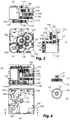
- FIG. 3 shows a top plan view ( FIG. 3 a , wherein lower hidden components are also shown), a front view ( FIG. 3 b ) and a right side view ( FIG. 3 c ) of a part of the components contained within the housing of FIG. 2 ;
- FIG. 4 shows a first top plan view ( FIG. 4 a ) and a section view according to the plane AA of FIG. 4 a ( FIG. 4 b ) of the housing and of a part of the components contained therein, as well as a front view ( FIG. 4 c ) and a top plan view ( FIG. 4 d ) of a toothed wheel of the peristaltic pump of FIG. 1 ;
- FIG. 5 shows a top plan view of the housing, and of the components contained therein, of the peristaltic pump of FIG. 1 ;
- FIG. 6 shows a perspective front section view according to the plane BB of FIG. 5 ( FIG. 6 a ), an enlargement of a first particular ( FIG. 6 b ) and an enlargement of a second particular ( FIG. 6 c ) of such perspective front section view of FIG. 6 a;
- FIG. 7 shows a second top plan view of the housing, and of a part of the components contained therein, of the peristaltic pump of FIG. 1 ;
- FIG. 8 shows a section view according to the plane CC of FIG. 7 ( FIG. 8 a ) and an enlargement of a particular ( FIG. 8 b ) of the section view of FIG. 8 a;
- FIG. 9 shows a top plan view of a square printed circuit board for obtaining two printed circuit boards of the type used in the peristaltic pump of FIG. 1 ;
- FIG. 10 shows a top plan view ( FIG. 10 a ) and a right side view ( FIG. 10 b ) of a first arrangement of a bracket attached to the peristaltic pump of FIG. 1 , a top plan view ( FIG. 10 c ) and a right side view ( FIG. 10 d ) of a second arrangement of a bracket attached to the peristaltic pump of FIG. 1 , a top plan view ( FIG. 10 e ) and a right side view ( FIG. 10 f ) of a third arrangement of a bracket attached to the peristaltic pump of FIG. 1 , a top plan view ( FIG. 10 g ) and a right side view ( FIG.
- FIG. 10 h of a fourth arrangement of a bracket attached to the peristaltic pump of FIG. 1 , a top plan view ( FIG. 10 i ) and a right side view ( FIG. 10 j ) of a fifth arrangement of a bracket attached to the peristaltic pump of FIG. 1 , a top plan view ( FIG. 10 k ) and a right side view ( FIG. 10 l ) of a sixth arrangement of a bracket attached to the peristaltic pump of FIG. 1 , a top plan view ( FIG. 10 m ) and a right side view ( FIG. 10 n ) of a seventh arrangement of a bracket attached to the peristaltic pump of FIG. 1 , and a top plan view ( FIG. 10 o ) and a right side view ( FIG. 10 p ) of an eighth arrangement of a bracket attached to the peristaltic pump of FIG. 1 ;
- FIG. 11 shows a perspective view of the fifth arrangement of FIGS. 10 i and 10 j fixed to an external wall ( FIG. 11 a ), a perspective view of the third arrangement of FIGS. 10 e and 10 f fixed to an external wall ( FIG. 11 b ), a perspective view of the seventh arrangement di FIGS. 10 m and 10 n fixed to an external wall ( FIG. 11 c ), a perspective view of the first arrangement di FIGS. 10 a and 10 b fixed to an external wall ( FIG. 11 d ), a perspective view of the fourth arrangement di FIGS. 10 g and 10 h fixed to an external wall ( FIG. 11 e ), a perspective view of the eighth arrangement di FIGS. 10 o and 10 p fixed to an external wall ( FIG. 11 f ), and a perspective view of the second arrangement di FIGS. 10 c and 10 d fixed to an external wall ( FIG. 11 g );
- FIG. 12 shows a top plan view ( FIG. 12 a ) and a right side view ( FIG. 12 b ) of a first orientation of coupling of the head to the housing of the peristaltic pump of FIG. 1 , a top plan view ( FIG. 12 c ) and a right side view ( FIG. 12 d ) of a second orientation of coupling of the head to the housing of the peristaltic pump of FIG. 1 , a top plan view ( FIG. 12 e ) and a right side view ( FIG. 12 f ) of a third orientation of coupling of the head to the housing of the peristaltic pump of FIG. 1 , and a top plan view ( FIG. 12 g ) and a right side view ( FIG. 12 h ) of a fourth orientation of coupling of the head to the housing of the peristaltic pump of FIG. 1 ;
- FIG. 13 shows two perspective front views of the first orientation of FIGS. 12 a and 12 b wherein the head and the housing are separated ( FIG. 13 a ) and coupled ( FIG. 13 b ), two perspective front views of the second orientation of FIGS. 12 c and 12 d wherein the head and the housing are separated ( FIG. 13 c ) and coupled ( FIG. 13 d ), two perspective front views of the third orientation of FIGS. 12 e and 12 f wherein the head and the housing are separated ( FIG. 13 e ) and coupled ( FIG. 13 f ), and two perspective front views of the fourth orientation of FIGS. 12 g and 12 h wherein the head and the housing are separated ( FIG. 13 g ) and coupled ( FIG. 13 h ); and
- FIG. 14 shows a perspective front right view ( FIG. 14 a ), a perspective front left view ( FIG. 14 b ), a perspective rear right view ( FIG. 14 c ) and a perspective rear left view ( FIG. 14 d ) of a bracket applicable to the peristaltic pump of FIG. 1 .
- a preferred embodiment of the peristaltic pump according to the invention is a dosing pump having a housing 100 and a head 200 which may be removably coupled to each other.
- the housing 100 contains the electrical components, e.g.
- the housing 100 substantially has the shape of a rectangular parallelepiped devoid of a face (i.e., the five external surfaces of its walls, devoid of projections and possibly provided with holes and/or notches, are planar and lie on the faces of a rectangular parallelepiped—whereby each side wall is configured to rest on an external planar wall), in particular a rectangular parallelepiped close to a cubic shape, wherein the dimensions of the three sides do not differ from each other by more than 30%.
- a rectangular parallelepiped devoid of a face i.e., the five external surfaces of its walls, devoid of projections and possibly provided with holes and/or notches, are planar and lie on the faces of a rectangular parallelepiped—whereby each side wall is configured to rest on an external planar wall
- a rectangular parallelepiped close to a cubic shape wherein the dimensions of the three sides do not differ from each other by more than 30%.
- the housing 100 substantially has the shape of a rectangular parallelepiped with square base the inside of which is accessible from the missing face of it; conventionally, in the following of the description it will be assumed that the missing wall of the housing 100 is the upper wall, whereby the housing 100 has hollow top.
- the rear wall of the housing 100 comprises a notch 105 configured to house a duct 108 (shown in FIG.
- the duct 108 is optionally orientable since it has the upper end hinged within the notch 105 ) that houses two electrical terminals for supplying power to the printed circuit board contained within the housing 100 ; advantageously, the two electrical terminals are male terminals, optionally Faston blade ones, configured to connect with corresponding external female terminals for making male-female electrical connections.
- Other embodiments of the peristaltic pump according to the invention may be devoid of the duct 108 and/or comprise three (instead of two) power electrical terminals and/or terminals different from male Faston blade terminals (e.g. female Faston terminals, or male or female terminals not of Faston type).
- Slots 610 configured to allow a snap-fit connection with some plates contained in the same housing 100 , as it will be better illustrated later with reference to FIGS. 5 and 6 , are present on the four side walls of the housing 100 .
- the head 200 of the peristaltic pump houses a rotor provided with two or more (optionally two or three) rollers (or similar elements) and the tube that is squeezed by the rollers; in this regard, the rotor, the rollers and the tube are not shown in the Figures.
- the head 200 has a hollow base configured to be coupled to the top of the housing 100 (i.e. in correspondence of the missing upper wall of the latter), where the hollow base of the head 200 is delimited by four side walls arranged on the side faces of a rectangular parallelepiped having square base having side L (equal to the side of the square base of the housing 100 ).
- the head 200 superiorly comprises a projecting upper portion 230 in turn provided with a projection 235 .
- peristaltic pump may have other specific shapes and dimensions of the head 200 , that still has a hollow base configured to be coupled to the top of the housing 100 (i.e. in correspondence of the missing upper wall of the latter), wherein the head 200 is contained or inscribable in a rectangular parallelepiped having base identical to the base of the rectangular parallelepiped of the housing 100 and height H 200 optionally smaller than the height H 100 of the housing 100 and more optionally ranging from 20% to 50% of the latter: 0.2 ⁇ H 100 ⁇ H 200 ⁇ 0.5 ⁇ H 100
- the hub of the rotor is mechanically connected to the reduction gear housed within the housing 100 so that the rotor is set in rotation by the electric motor, also housed within the housing 100 , when this is operated, whereby the rollers are set in rotation thus squeezing the tube according to a peristaltic operation.
- the features of the shape of the peristaltic pump (in particular with reference to the housing 100 and head 200 ) devoid of projections on the side walls of the housing 100 are not features essential to the invention.
- the head 200 is provided on an upper surface easily accessible with (at least) one slot 240 for accessing two adjusting electronic components, also known as trimmers, for adjusting the speed of the (electric motor and, consequently, of the) rotor of the head 200 ; such electronic components are on a printed circuit board housed within the housing 100 , as it will be illustrated later.
- the peristaltic pump may comprise more than one slot for accessing the trimmers (which may be also in a number different from two, for instance only one trimmer or three or more trimmer) and/or one or more slots for accessing the trimmers in position different from that shown in the Figures for the preferred embodiment of the peristaltic pump according to the invention.
- the shape of the slot(s) for accessing the trimmers is not a feature essential to the invention.
- the housing 100 contains an electric motor 130 , configured to set a main pinion 135 , that is inferiorly positioned (i.e. towards the base of the housing 100 ), in rotation, and a reduction gear comprising a first toothed wheel 120 provided with a first secondary pinion 121 , a second wheel 122 provided with a second secondary pinion 123 , a third wheel 124 provided with a third secondary pinion 125 , and a fourth wheel 126 provided with a fourth secondary pinion 127 , superiorly positioned at the centre of the hollow top of the housing 100 . As shown in FIGS.
- the toothed wheels 120 , 122 , 124 and 126 of the reduction gear are all equal to the same type and size of toothed wheel 20 provided with secondary pinion 21 , the base of which has a smooth collar 22 , wherein the toothed wheel 20 has an axial through hole 22 in which an axis may be inserted.
- Other embodiments of the peristaltic pump according to the invention may comprise a reduction gear comprising two or more toothed wheels different from each other.
- the main pinion 135 is configured to interact with the first toothed wheel 120 , the (first) secondary pinion 121 of which is in turn configured to interact with the second toothed wheel 122 , the (second) secondary pinion 123 of which is in turn configured to interact with the third toothed wheel 124 , the (third) secondary pinion 125 of which is in turn configured to interact with the fourth toothed wheel 126 , the (fourth) secondary pinion 127 of which is in turn configured to be mechanically connected to the hub of the rotor housed within the head 200 , when the latter is coupled to the housing 100 , so that the rotor is set in rotation when the electric motor is operated.
- Other embodiments of the peristaltic pump according to the invention may comprise a different arrangement of the reduction gear, comprising one or more toothed wheels which may be also devoid of respective secondary pinions.
- the housing 100 further contains a lower alignment plate 140 and an upper alignment plate 150 configured to be snap-fit connected to the housing 100 in respective positions, so as to make the toothed wheels 120 , 122 , 124 and 126 of the reduction gear appropriately align, also with the aid of the internal surface of the base of the housing 100 .
- the axis 136 of the first toothed wheel 120 has the lower end positioned in a corresponding notch (not shown) of the internal surface of the base of the housing 100 and the upper end positioned in a respective notch of the lower surface of the lower alignment plate 140 (the corresponding protrusion 146 of which is visible on the upper surface); similarly, the axis 137 of the second toothed wheel 122 has the lower end positioned in a corresponding notch (not shown) of the internal surface of the base of the housing 100 and the upper end positioned in a respective notch of the lower surface of the lower alignment plate 140 (the corresponding protrusion 147 of which is visible on the upper surface); the axis 138 of the third toothed wheel 124 has the lower end positioned in a corresponding notch of a protrusion (not shown) of the internal surface of the base of the housing 100 and the upper end positioned in a respective notch of the lower surface of the upper alignment plate 150 (the corresponding protrusion 158 of which is visible on
- the housing 100 also contains a printed circuit board 160 for controlling the peristaltic pump, that is provided with two slots 161 , configured to house the two power supply terminals 131 of the electric motor 130 insertable into the two slots 161 (as shown in greater detail in FIG. 8 ), with two downwardly projecting male blade terminals 162 , for connection to an external power supply (through corresponding terminals housed within the duct 108 shown in FIG. 11 e ), and with two trimmers 163 for adjusting the speed of the electric motor and, consequently, of the rotor of the head 200 .
- the housing 100 contains a protective plate 170 (not shown in FIGS. 3 and 4 ), optionally made of plastics, configured to snap-fit connect on the perimeter of the board 160 so as to cover the same board 160 .
- the lower alignment plate 140 and the upper alignment plate 150 are provided with snap-fit teeth 609 which are configured to insert into corresponding slots 610 of at least two, optionally three, more optionally four, side walls of the housing 100 .
- the snap-fit teeth 609 are slid along corresponding alignment guides 608 , with which the side walls of the housing 100 are provided, down to insert into the slots 610 ; obviously, while the teeth 609 slide along the corresponding alignment guides 608 , the plate to which the teeth 609 belong and the side walls of the housing 100 to which the corresponding alignment guides 608 belong elastically bend.
- the lower alignment plate 140 and the upper alignment plate 150 are configured to be snap-fit connected to the housing 100 , in a removable or not removable manner.
- the peristaltic pump according to the invention is provided with a reduction gear integrated inside the housing 100 that uses a single type of toothed wheel provided with pinion, advantageously made of plastics. All the components of the reduction gear are fixed through plates, also advantageously made of plastics, coupled to the housing 100 through snap-fits, without using any screw. Furthermore, power is supplied to the electric motor through terminals which do not create any projection nor any wiring. This allows to simplify assembling, installation and maintenance operations, at the same time reducing their costs, unlike the prior art peristaltic pumps which use commercial gear motors fixed with screws inside the casing. Moreover, the arrangement of the peristaltic pump according to the invention is compact and handy.
- the features related to the snap-fit connection are not features essential to the invention.
- the printed circuit board 160 for controlling the peristaltic pump has a shape close to the one of an equilateral right triangle. As shown in FIG.
- the printed circuit board 160 for controlling the peristaltic pump snap-fit connects to the side walls of the housing 100 similarly to what illustrated with reference to the lower alignment plate 140 and upper alignment plate 150 .
- peristaltic pump may have the printed circuit board having a similar configuration, wherein two boards are obtainable (in an antisymmetric way) by separating two portions of a rectangular or square board along a section line, not necessarily but optionally at least partially arranged along a diagonal of the rectangle or square, and wherein optionally the two boards are provided with at least one pair of portions being slightly offset from such diagonal, wherein a first portion of the pair is projecting with respect to the diagonal and a second portion of the pair is recessed with respect to the diagonal.
- the features related to the electronics comprising a control printed circuit board having the specific configuration illustrated with reference to FIG. 7-9 may be present in the peristaltic pump according to the invention independently from the other features, i.e. independently from the shape of the peristaltic pump (in particular with reference to the housing 100 and head 200 ) devoid of projections on the side walls of the housing 100 , and independently from the features related to the snap-fit connection (devoid of screws and similar elements, i.e. exclusively with snap-fits) of the components contained within the housing 100 and related to the reduction gear, i.e. that the peristaltic pump is also provided with such other features related to the shape and snap-fit connection.
- the square base shape of the housing 100 allows to apply a single type of bracket to all the side walls of the same housing 100 at two possible heights with respect to the base of the housing 100 .
- two pairs of notches are present on all the four side walls of the housing 100 at two different heights: a pair of upper notches 650 A and a pair of lower notches 650 B.
- the two upper or lower notches 650 A or 650 B of each pair are advantageously located in proximity of the two edges separating the side wall (to which the upper or lower notches 650 A or 650 B under consideration belong) from the contiguous side walls, and the upper and lower notches 650 A and 650 B are at the same distance from the closest edge.
- the upper and lower notches 650 A and 650 B on the front wall 700 are located in proximity of the two edges 750 and 760 separating the front wall 700 from the left side wall 730 and from the right side wall 710 , respectively. As particularly shown in FIG.
- each upper and lower notch 650 A and 650 B on the side walls comprises a pair of holes 660 into which, as shown in detail in FIG. 14 , a pair of corresponding teeth 815 are insertable, with which corresponding teeth two side engagement elements 810 are provided, having two slabs integrally coupled to each other for forming a L-profile, with which a bracket 800 is provided, which bracket comprises two orthogonal plates 802 and 804 integrally coupled to each other (whereby the bracket 800 is shaped according a L-profile) provided with slots 806 and/or through holes 808 in which screws 850 (or similar fastening means) are insertable for fixing the peristaltic pump to an external wall 950 ; in particular, the two side engagement elements 810 integrally coupled to the plate 802 of the bracket 800 , and the axis of the junction of the two slabs of each one of the two side engagement elements 810 is orthogonal to the axis of the junction of the two plates 802 and 804 .
- each one of the two L-shaped side engagement elements 810 of a bracket 800 comprises a pair of teeth 815 on the internal surface of the slab that is outermost with respect to the bracket 800 , between the two forming the side element 810 , that is orthogonal to the two plates 802 and 804 , so that the two side engagement elements 810 engage with two respective pairs of upper or lower notches 650 A or 650 B present on the side walls of the housing 100 adjacent to the side wall on which the plate 802 rests and with respect to which side wall the other plate 804 of the bracket 800 is disposed parallel.
- the bracket 800 is configured to couple to the housing 100 , being disposed parallel to a side wall of the housing 100 , through snap-fit insertion of the pairs of teeth of the two side engagement elements 810 in two respective pairs of notches 650 A or 650 B present on the walls adjacent to such parallel side wall of the housing 100 .
- the bracket 800 is configured to removably engage with the housing 100 .
- the peristaltic pump may be fixed to an external wall 950 by fastening a bracket 800 to the housing 100 in the following positions: a first position wherein the bracket is parallel to the rear wall 720 of the housing 100 at the height of the lower notches 650 B ( FIGS. 10 a , 10 b and 11 d ); a second position wherein the bracket is parallel to the rear wall 720 of the housing 100 at the height of the upper notches 650 A ( FIGS. 10 c , 10 d and 11 g ); a third position wherein the bracket is parallel to the left side wall 730 of the housing 100 at the height of the lower notches 650 B ( FIGS.
- FIGS. 10 e , 10 f and 11 b a fourth position wherein the bracket is parallel to the left side wall 730 of the housing 100 at the height of the upper notches 650 A ( FIGS. 10 g , 10 h and 11 e ); a fifth position wherein the bracket is parallel to the front wall 700 of the housing 100 at the height of the lower notches 650 B ( FIGS. 10 i , 10 j and 11 a ); a sixth position wherein the bracket is parallel to the front wall 700 of the housing 100 at the height of the upper notches 650 A ( FIGS. 10 k and 10 l ); a seventh position wherein the bracket is parallel to the right side wall 710 of the housing 100 at the height of the lower notches 650 B ( FIGS.
- peristaltic pump it is also possible to fix the peristaltic pump to one or more external walls by fastening two or more brackets 800 to the housing 100 .
- the two trimmer 163 for adjusting the speed of the electric motor are not accessible, because the slot 240 of the head 200 is not positioned above the trimmers 163 (since the printed circuit board 160 for controlling the peristaltic pump is stably coupled to the housing 100 independently from the orientation of the head 200 ).
- the two trimmers 163 it is necessary to adjust the two trimmers 163 before coupling the head 200 to the housing 100 .
- peristaltic pump according to the invention may comprise more than one slot for accessing the trimmers, so that these are accessible even in more than one orientation of coupling of the head to the housing that is different from the first orientation.
- peristaltic pump may have the adjusting trimmers directly coupled to the head 200 (instead of the printed circuit board), advantageously on the its top so that they are easily accessible, and they may have each adjusting trimmer that is connected to two or more respective electrical terminals (each comprising the number of wires or traces necessary to the connection with a trimmer, for instance two wires or traces) coupled to the head 200 , only one of which, depending on the orientation of the head 200 with respect to the housing 100 , connects to a terminal of the printed circuit board coupled to the housing 100 that corresponds to that trimmer.
- the trimmers are always accessible and operative for any orientation of the head 200 with respect to the housing 100 .
- peristaltic pump wherein the base of the housing is rectangular instead of square, allows the head to be coupled to the housing only according to two different orientations, unless they have a square base (or even circular) head that may be coupled to the housing in correspondence of a square shaped (or even circular) upper aperture of the same housing.
Landscapes
- Engineering & Computer Science (AREA)
- Mechanical Engineering (AREA)
- General Engineering & Computer Science (AREA)
- Microelectronics & Electronic Packaging (AREA)
- Power Engineering (AREA)
- Computer Hardware Design (AREA)
- Reciprocating Pumps (AREA)
- Mounting Of Printed Circuit Boards And The Like (AREA)
- Connection Of Motors, Electrical Generators, Mechanical Devices, And The Like (AREA)
Abstract
Description
H 100=0.8·L
In other words, the
H 200=0.37·H 100
whereby the whole height HP (excluding the projection 235) is larger than the side L of the base square of the housing 100 (and of the head 200) by about 17%, i.e.:
H P =H 100 +H 200=1.17·L
0.2·H 100 ≤H 200≤0.5·H 100
When the
-
- the
head 200 is coupled to thehousing 100 so that the fourthsecondary pinion 127 mechanically connects to thehub 250 of the rotor housed within thehead 200, as shown inFIG. 13a , according to a first orientation wherein the first andsecond joints front wall 700 of thehousing 100, as shown inFIGS. 12a, 12b and 13 b; - the
head 200 is coupled to thehousing 100 so that the fourthsecondary pinion 127 mechanically connects to thehub 250 of the rotor housed within thehead 200, as shown inFIG. 13c , according to a second orientation wherein the first andsecond joints right side wall 710 of thehousing 100, as shown inFIGS. 12c, 12d and 13 d; - the
head 200 is coupled to thehousing 100 so that the fourthsecondary pinion 127 mechanically connects to thehub 250 of the rotor housed within thehead 200, as shown inFIG. 13e , according to a third orientation wherein the first andsecond joints rear wall 720 of thehousing 100, as shown inFIGS. 12e, 12f and 13f ; and - the
head 200 is coupled to thehousing 100 so that the fourthsecondary pinion 127 mechanically connects to thehub 250 of the rotor housed within thehead 200, as shown inFIG. 13g , according to a fourth orientation wherein the first andsecond joints left side wall 730 of thehousing 100, as shown inFIGS. 12g, 12h and 13 h.
- the
Claims (10)
Applications Claiming Priority (4)
| Application Number | Priority Date | Filing Date | Title |
|---|---|---|---|
| ITRM20150007 | 2015-01-08 | ||
| ITRM2015A0007 | 2015-01-08 | ||
| ITRM2015A000007 | 2015-01-08 | ||
| PCT/IB2016/050058 WO2016110813A1 (en) | 2015-01-08 | 2016-01-07 | Peristaltic pump |
Publications (2)
| Publication Number | Publication Date |
|---|---|
| US20170350389A1 US20170350389A1 (en) | 2017-12-07 |
| US10788036B2 true US10788036B2 (en) | 2020-09-29 |
Family
ID=52633480
Family Applications (1)
| Application Number | Title | Priority Date | Filing Date |
|---|---|---|---|
| US15/535,562 Active 2036-09-23 US10788036B2 (en) | 2015-01-08 | 2016-01-07 | Peristaltic pump |
Country Status (8)
| Country | Link |
|---|---|
| US (1) | US10788036B2 (en) |
| EP (1) | EP3247905B1 (en) |
| JP (1) | JP6668358B2 (en) |
| CN (1) | CN107110150B (en) |
| ES (1) | ES2689667T3 (en) |
| PL (1) | PL3247905T3 (en) |
| PT (1) | PT3247905T (en) |
| WO (1) | WO2016110813A1 (en) |
Families Citing this family (5)
| Publication number | Priority date | Publication date | Assignee | Title |
|---|---|---|---|---|
| DE102019006414B4 (en) * | 2019-09-11 | 2021-09-23 | Blum-Novotest Gmbh | ADJUSTMENT DEVICE AND CHIPPING SYSTEM |
| US11421672B2 (en) | 2019-12-05 | 2022-08-23 | Hach Company | Linear peristaltic pump with pinch and compression block arrangement |
| USD939692S1 (en) * | 2019-12-24 | 2021-12-28 | Baoding Shenchen Precision Pump Co., Ltd. | Peristaltic pump head |
| USD958840S1 (en) * | 2020-01-31 | 2022-07-26 | Aspen Pumps Limited | Peristaltic pump |
| EP4069932A1 (en) * | 2020-06-05 | 2022-10-12 | Renson Sunprotection Screens NV | Method for manufacturing an awning device |
Citations (15)
| Publication number | Priority date | Publication date | Assignee | Title |
|---|---|---|---|---|
| US4313150A (en) * | 1979-09-24 | 1982-01-26 | Northern Telecom Limited | Latching lever for printed circuit boards |
| DE3108129A1 (en) | 1981-03-04 | 1982-09-16 | Olympia Werke Ag, 2940 Wilhelmshaven | Low-throughput rotary hose pump |
| EP0881389A2 (en) | 1997-05-30 | 1998-12-02 | Bredel Hose Pumps B.V. | Peristaltic pumpheads |
| US20070148010A1 (en) | 2003-09-26 | 2007-06-28 | Stephan Michels | Peristaltic pump |
| US20080168651A1 (en) | 2007-01-12 | 2008-07-17 | Endicott Interconnect Technologies, Inc. | Method of providing a printed circuit board with an edge connection portion and/or a plurality of cavities therein |
| US20080301933A1 (en) | 2007-06-07 | 2008-12-11 | Endicott Interconnect Technologies, Inc. | Method of providing a printed circuit board with an edge connection portion |
| US20090140585A1 (en) * | 2007-11-30 | 2009-06-04 | Albert Keith Pant | Interface connector for a motor and a motor incorporating the interface connector |
| EP2098729A1 (en) | 2008-03-07 | 2009-09-09 | Carpigiani Group - Ali S.p.A. | Peristaltic pump |
| US20100117468A1 (en) * | 2006-09-29 | 2010-05-13 | Nidec Sankyo Corporation | Fan motor |
| US20100129248A1 (en) | 2008-11-21 | 2010-05-27 | Duen-Gang Mou | Tube loading assembly for peristaltic pump |
| US20110215115A1 (en) * | 2010-03-02 | 2011-09-08 | Proper Scott T | Counter mounted dispensing system with above-counter refill unit |
| US20130154411A1 (en) * | 2011-12-16 | 2013-06-20 | Continental Automotive Systems, Inc. | Electromagnetic compatibility printed circuit board |
| US20130234567A1 (en) | 2012-03-07 | 2013-09-12 | Robert Bosch Gmbh | Electric machine for the motorized adjustment of movable parts in the motor vehicle, and method for producing the electric machine |
| US20130251561A1 (en) | 2005-08-05 | 2013-09-26 | Molon Motor And Coil Corporation | Fluid Pump System |
| US20140010675A1 (en) * | 2011-02-15 | 2014-01-09 | Barry Kent | Pump for sterilisation apparatus |
Family Cites Families (5)
| Publication number | Priority date | Publication date | Assignee | Title |
|---|---|---|---|---|
| JPH09172232A (en) * | 1995-12-21 | 1997-06-30 | Fuji Photo Film Co Ltd | Aggregate board, its manufacture and manufacture of dividing board |
| JP2001024312A (en) * | 1999-07-13 | 2001-01-26 | Taiyo Yuden Co Ltd | Manufacture of electronic device, the electronic device, and method for filling resin |
| JP5876853B2 (en) * | 2008-02-14 | 2016-03-02 | セイコーエプソン株式会社 | Micro pump, tube unit |
| CN202690388U (en) * | 2012-01-19 | 2013-01-23 | 佶庆电机有限公司 | Precise quantitative peristaltic pump and device thereof |
| JP6475502B2 (en) * | 2015-01-30 | 2019-02-27 | 本田技研工業株式会社 | Circuit board held and fixed by mechanical structure, and electronic device using the same |
-
2016
- 2016-01-07 ES ES16707947.4T patent/ES2689667T3/en active Active
- 2016-01-07 US US15/535,562 patent/US10788036B2/en active Active
- 2016-01-07 PL PL16707947T patent/PL3247905T3/en unknown
- 2016-01-07 WO PCT/IB2016/050058 patent/WO2016110813A1/en active Application Filing
- 2016-01-07 PT PT16707947T patent/PT3247905T/en unknown
- 2016-01-07 EP EP16707947.4A patent/EP3247905B1/en active Active
- 2016-01-07 JP JP2017534357A patent/JP6668358B2/en active Active
- 2016-01-07 CN CN201680004435.0A patent/CN107110150B/en active Active
Patent Citations (15)
| Publication number | Priority date | Publication date | Assignee | Title |
|---|---|---|---|---|
| US4313150A (en) * | 1979-09-24 | 1982-01-26 | Northern Telecom Limited | Latching lever for printed circuit boards |
| DE3108129A1 (en) | 1981-03-04 | 1982-09-16 | Olympia Werke Ag, 2940 Wilhelmshaven | Low-throughput rotary hose pump |
| EP0881389A2 (en) | 1997-05-30 | 1998-12-02 | Bredel Hose Pumps B.V. | Peristaltic pumpheads |
| US20070148010A1 (en) | 2003-09-26 | 2007-06-28 | Stephan Michels | Peristaltic pump |
| US20130251561A1 (en) | 2005-08-05 | 2013-09-26 | Molon Motor And Coil Corporation | Fluid Pump System |
| US20100117468A1 (en) * | 2006-09-29 | 2010-05-13 | Nidec Sankyo Corporation | Fan motor |
| US20080168651A1 (en) | 2007-01-12 | 2008-07-17 | Endicott Interconnect Technologies, Inc. | Method of providing a printed circuit board with an edge connection portion and/or a plurality of cavities therein |
| US20080301933A1 (en) | 2007-06-07 | 2008-12-11 | Endicott Interconnect Technologies, Inc. | Method of providing a printed circuit board with an edge connection portion |
| US20090140585A1 (en) * | 2007-11-30 | 2009-06-04 | Albert Keith Pant | Interface connector for a motor and a motor incorporating the interface connector |
| EP2098729A1 (en) | 2008-03-07 | 2009-09-09 | Carpigiani Group - Ali S.p.A. | Peristaltic pump |
| US20100129248A1 (en) | 2008-11-21 | 2010-05-27 | Duen-Gang Mou | Tube loading assembly for peristaltic pump |
| US20110215115A1 (en) * | 2010-03-02 | 2011-09-08 | Proper Scott T | Counter mounted dispensing system with above-counter refill unit |
| US20140010675A1 (en) * | 2011-02-15 | 2014-01-09 | Barry Kent | Pump for sterilisation apparatus |
| US20130154411A1 (en) * | 2011-12-16 | 2013-06-20 | Continental Automotive Systems, Inc. | Electromagnetic compatibility printed circuit board |
| US20130234567A1 (en) | 2012-03-07 | 2013-09-12 | Robert Bosch Gmbh | Electric machine for the motorized adjustment of movable parts in the motor vehicle, and method for producing the electric machine |
Also Published As
| Publication number | Publication date |
|---|---|
| PL3247905T3 (en) | 2019-01-31 |
| WO2016110813A1 (en) | 2016-07-14 |
| CN107110150A (en) | 2017-08-29 |
| JP2018508681A (en) | 2018-03-29 |
| CN107110150B (en) | 2019-05-28 |
| JP6668358B2 (en) | 2020-03-18 |
| PT3247905T (en) | 2018-10-30 |
| US20170350389A1 (en) | 2017-12-07 |
| ES2689667T3 (en) | 2018-11-15 |
| EP3247905A1 (en) | 2017-11-29 |
| EP3247905B1 (en) | 2018-07-25 |
Similar Documents
| Publication | Publication Date | Title |
|---|---|---|
| US10451055B2 (en) | Peristaltic pump head having a reduction gear and triangular circuit board snap-fit to a pump housing and having changeable orientations | |
| US10788036B2 (en) | Peristaltic pump | |
| US20150165392A1 (en) | Foam-at-a-distance systems, foam generators and refill units | |
| US6938883B2 (en) | Guide for selectively receiving a wick in a dispenser for a volatile liquid | |
| US20120305672A1 (en) | Integrated pneumatic spray device | |
| US10299394B2 (en) | Electrical function cassette having waterproof function and ventilating fan employing the same | |
| EP3742065A1 (en) | Electronic control assembly and air conditioner | |
| JP6813482B2 (en) | Diaphragm pump with duck bill valve, multi-directional port and flexible electrical connectivity | |
| US6174142B1 (en) | Elastomeric pump housing | |
| US7902522B2 (en) | Submersible pump with UV sterilization device | |
| CN112901507A (en) | Liquid cooling type heat dissipation system and pump thereof | |
| CN207572678U (en) | Electric device | |
| CN205648290U (en) | Circuit board components | |
| CN212909191U (en) | Motor and robot joint | |
| CN210068540U (en) | Handle assembly mechanism and fan thereof | |
| JP2012518219A (en) | Beverage vending machine | |
| US8360420B2 (en) | Paper adjusting device | |
| CN210772691U (en) | Air supply structure of air conditioner | |
| CN215583930U (en) | Base for bearing cup body and wall breaking machine | |
| CN217107379U (en) | Protection continuation of journey industry distributor | |
| KR200479495Y1 (en) | Grill assembly for ventilator | |
| CN211707315U (en) | Embedded installation supersonic generator | |
| CN216481304U (en) | Wall-mounted air conditioner indoor unit and air conditioner | |
| CN215605173U (en) | Base for bearing cup body and wall breaking machine | |
| JP2004156832A (en) | Air conditioner |
Legal Events
| Date | Code | Title | Description |
|---|---|---|---|
| AS | Assignment |
Owner name: SEKO S.P.A., ITALY Free format text: ASSIGNMENT OF ASSIGNORS INTEREST;ASSIGNORS:QUINTARELLI, MAURO;ESPOSITO, LUIGINO;REEL/FRAME:043394/0840 Effective date: 20170612 |
|
| STPP | Information on status: patent application and granting procedure in general |
Free format text: DOCKETED NEW CASE - READY FOR EXAMINATION |
|
| STPP | Information on status: patent application and granting procedure in general |
Free format text: NON FINAL ACTION MAILED |
|
| STPP | Information on status: patent application and granting procedure in general |
Free format text: RESPONSE TO NON-FINAL OFFICE ACTION ENTERED AND FORWARDED TO EXAMINER |
|
| STPP | Information on status: patent application and granting procedure in general |
Free format text: NON FINAL ACTION MAILED |
|
| STPP | Information on status: patent application and granting procedure in general |
Free format text: NOTICE OF ALLOWANCE MAILED -- APPLICATION RECEIVED IN OFFICE OF PUBLICATIONS |
|
| STCF | Information on status: patent grant |
Free format text: PATENTED CASE |
|
| FEPP | Fee payment procedure |
Free format text: MAINTENANCE FEE REMINDER MAILED (ORIGINAL EVENT CODE: REM.); ENTITY STATUS OF PATENT OWNER: LARGE ENTITY |