EP3742065A1 - Electronic control assembly and air conditioner - Google Patents
Electronic control assembly and air conditioner Download PDFInfo
- Publication number
- EP3742065A1 EP3742065A1 EP18900031.8A EP18900031A EP3742065A1 EP 3742065 A1 EP3742065 A1 EP 3742065A1 EP 18900031 A EP18900031 A EP 18900031A EP 3742065 A1 EP3742065 A1 EP 3742065A1
- Authority
- EP
- European Patent Office
- Prior art keywords
- electronic control
- section
- limit
- control box
- box assembly
- Prior art date
- Legal status (The legal status is an assumption and is not a legal conclusion. Google has not performed a legal analysis and makes no representation as to the accuracy of the status listed.)
- Withdrawn
Links
Images


Classifications
-
- F—MECHANICAL ENGINEERING; LIGHTING; HEATING; WEAPONS; BLASTING
- F24—HEATING; RANGES; VENTILATING
- F24F—AIR-CONDITIONING; AIR-HUMIDIFICATION; VENTILATION; USE OF AIR CURRENTS FOR SCREENING
- F24F13/00—Details common to, or for air-conditioning, air-humidification, ventilation or use of air currents for screening
- F24F13/20—Casings or covers
-
- F—MECHANICAL ENGINEERING; LIGHTING; HEATING; WEAPONS; BLASTING
- F24—HEATING; RANGES; VENTILATING
- F24F—AIR-CONDITIONING; AIR-HUMIDIFICATION; VENTILATION; USE OF AIR CURRENTS FOR SCREENING
- F24F11/00—Control or safety arrangements
- F24F11/89—Arrangement or mounting of control or safety devices
-
- F—MECHANICAL ENGINEERING; LIGHTING; HEATING; WEAPONS; BLASTING
- F24—HEATING; RANGES; VENTILATING
- F24F—AIR-CONDITIONING; AIR-HUMIDIFICATION; VENTILATION; USE OF AIR CURRENTS FOR SCREENING
- F24F13/00—Details common to, or for air-conditioning, air-humidification, ventilation or use of air currents for screening
- F24F13/20—Casings or covers
- F24F2013/207—Casings or covers with control knobs; Mounting controlling members or control units therein
Definitions
- the present invention relates to the technical field of air conditioners, in particular to an electronic control assembly and an air conditioner.
- An air conditioner contains an electronic control box, which is used to control the start and stop and operation of the air conditioner.
- the electronic control box needs to be fixed to the base.
- the electronic control box is connected to the base through multiple screws, and the use of screws is prone to produce screw column to be striped and other phenomena with unreliable quality. With the use of screw connection, the whole is not easy to detach. And the production efficiency of the screwing is low, which increases the cost.
- an electronic control assembly is proposed in the present invention.
- the electronic control assembly is convenient to detach, which reduces the cost of the electronic control assembly.
- An electronic control assembly includes a base and an electronic control box assembly, wherein a limiting member is disposed on the electronic control box assembly, a mounting member is disposed on the base, and the limiting member cooperate with the mounting member to limit the electronic control box assembly from moving relative to the base and to fix the electronic control box assembly and the base.
- the limiting member includes a limit portion, and the limit portion is disposed on one side of the electronic control box assembly.
- An abut portion is disposed on the mounting member, and the limit portion abuts against the abut portion.
- the abut portion includes an abut surface
- the limit portion includes a limit surface. After the limit portion slides into position relative to the abut portion, the limit surface abuts against the abut surface to limit a displacement of the electronic control box assembly relative to the base.
- the limit portion includes a first guide surface
- the abut portion includes a second guide surface. After the first guide surface (8) slides into position relative to the second guide surface, the limit surface abuts against the abut surface.
- the limit portion includes a guide section and a limit section, the guide section is connected to the mounting member, and the limit section is connected to one end of the guide section and is disposed at an acute angle.
- the second guide surface is disposed on one side of the guide section away from the limit section, and the limit surface is disposed on one side of the limit section away from the guide section.
- the limit portion further includes a reset section, and one end of the reset section is connected to one end of the limit section away from the guide section.
- the reset section drives the limit section and the guide section to rotate, so that the limit surface is released from abutment with the abut surface.
- the limiting member includes a latching portion, a snap portion is disposed in the mounting member, and the latching portion is latched with the snap portion.
- the latching portion includes a first latching segment and a second latching segment that are connected to each other and are L-shaped.
- the first latching segment has one end connected to the electronic control box assembly (3), and the other end connected to the second latching segment.
- the snap portion is a snap hole
- the snap hole comprises a first section, a transition section, and a second section.
- the first section is connected to the second section through the transition section, and a width of the first section is larger than a width of the second section.
- the electronic control assembly includes a base and an electronic control box assembly, wherein a limiting member is disposed on the electronic control box assembly, a mounting member is disposed on the base, and the limiting member cooperate with the mounting member to limit the electronic control box assembly from moving relative to the base and to fix the electronic control box assembly and the base.
- the cooperation of the limiting member and the mounting member can restrict the movement of the electronic control box assembly relative to the base, and can fix the electronic control box assembly and the base.
- the electronic control assembly is easy to detach, which reduces the cost of the electronic control assembly.
- Another object of the present invention is to provide an air conditioner, which is easy to disassemble and can reduce the cost of the electronic control assembly.
- An air conditioner includes an electronic control assembly.
- the electronic control assembly includes a base and an electronic control box assembly, wherein a limiting member is disposed on the electronic control box assembly, a mounting member is disposed on the base, and the limiting member cooperate with the mounting member to limit the electronic control box assembly from moving relative to the base and to fix the electronic control box assembly and the base.
- an electronic control assembly 1 is provided in this embodiment.
- the electronic control assembly 1 in this embodiment is easy to detach, which reduces the cost of the electronic control assembly 1.
- the electronic control assembly 1 includes a base 2 and an electronic control box assembly 3, wherein a limiting member 4 is disposed on the electronic control box assembly 3, a mounting member 5 is disposed on the base 2, and the limiting member 4 cooperates with the mounting member 5 to limit the electronic control box assembly 3 from moving relative to the base 2 and to fix the electronic control box assembly 3 and the base 2.
- the limiting member 4 cooperates with the mounting member 5 to limit the electronic control box assembly 3 from moving relative to the base 2 and to fix the electronic control box assembly 3 and the base 2.
- the electronic control assembly 1 is easy to detach, which reduces the cost of the electronic control assembly 1.
- the limiting member 4 includes a limit portion 6, and the limit portion 6 is disposed on one side of the electronic control box assembly 3.
- the limit portion 6 abuts against the mounting surface 5 to limit a displacement of the electronic control box assembly 3 relative to the base 2.
- the limit portion 6 has a limit surface 7. After the limit portion 6 slides into position relative to the mounting member 5, the limit surface 7 abuts against the mounting member 5 to limit a displacement of the electronic control box assembly 3 relative to the base 2.
- the limit portion 6 has a guide surface 8. After the guide surface 8 is slid into position relative to the mounting member 5, the limit surface 7 abuts against the mounting member 5.
- the limit portion 6 is a triangular prism, and the triangular prism has three side surfaces and two end surfaces, wherein one side surface is connected to a side wall of the electronic control box assembly 3. In another two side surfaces, one side surface is the abut surface 13, and the other is the first guide surface 8. Both the abut surface 13 and the first guide surface 8 extend to the side wall of the electronic control box assembly 3.
- the abut surface 13 is perpendicular to the side wall of the electronic control box assembly 3, and the first guide surface 8 is disposed at an acute angle with the side wall of the electronic control box assembly 3.
- the abut surface 13 is perpendicular to the side wall of the electronic control box assembly 3, and the first guide surface 8 is disposed at an acute angle with the side wall of the electronic control box assembly 3.
- the abut surface 13 is disposed at an acute angle with the side wall of the electronic control box assembly 3
- the first guide surface 8 is perpendicular to the side wall of the electronic control box assembly 3
- both the abut surface 13 and the first guide surface 8 is disposed at an acute angle with the side wall of the electronic control box assembly 3.
- the limiting member 4 further includes a latching portion 9, and the latching portion 9 is latched with the mounting member 5 for fixing the base 2 and the limiting member 4.
- the latching portion 9 is disposed at a bottom wall of the electronic box assembly 3 adjacent to the limit portion 6.
- the latching portion 9 includes a first latching segment 10 and a second latching segment 11 that are connected to each other and are L-shaped.
- the first latching segment 10 has one end connected to the electronic control box assembly 3, and the other end connected to the second latching segment 11.
- the second latching section 11 passes through the mounting member 5, and the first latching section 10 and the second latching section 11 move relative to the mounting member 5, so that the first latching section 10 abuts against the second latching section for fixing the base 2 and the electronic box assembly 3.
- the electronic box assembly 3 includes an electronic control box 23 and a protection plate 24, wherein the protection plate 24 is disposed outside the electronic control box 23, and in this embodiment, the limit portion 6 is disposed on the protection plate 24.
- the electronic control box assembly 3 includes the electronic control box 23 and the protection plate 24, which is not limited herein. In other embodiments of the present invention, the electronic box assembly 3 may only include the electronic control box 23, and the limit portion 6 is disposed on the electronic control box 23. Any solutions equivalent to this embodiment that may achieve the effects of this embodiment is within the protection scope of the present invention.
- an abut portion 12 is disposed on the mounting member 5, and the limit portion 6 abuts against the abut portion 12.
- the abut portion 12 has an abut surface 13. After the limit portion 6 is slid into position relative to the abut portion 12, the limit surface 7 abuts against the abut surface 13 to limit a displacement of the electronic control box assembly 3 relative to the base 2.
- the abut portion 12 has a second guide surface 14. After the first guide surface 8 is slid into position relative to the second guide surface 14, the limit surface 7 abuts against the abut surface 13.
- the first guide surface 8 abuts against the second guide surface 14 and slides relative to the second guide surface 14.
- the abut surface 13 abuts against the limit surface 7 to limit a displacement of the electronic control box assembly 3 relative to the base 2.
- the first guide surface 8 abuts against the second guide surface 14 and slides relative to the second guide surface 14.
- the first guide surface 8 slides relative to the second guide surface 14 to disengage from the second guide surface 14, indicating that the first guide surface 8 slides into position relative to the second guide surface 14.
- the limit portion 6 includes a guide section 15 and a limit section 16, wherein the guide section 15 is connected to the mounting member 5, the limit section 16 is connected to one end of the guide section 15 away from the mounting member 5 and disposed at an acute angle.
- the guide surface is disposed at one side of the guide section 15 away from the limit section 16, and the limit surface 7 is disposed at one side of the limit section 16 away from the guide section 15.
- the limit portion 6 further includes a reset section 17, and one end of the reset section 17 is connected to one end of the limit section 16 away from the guide section 15.
- the reset section 17 may drive the limit section 16 and the guide section 15 to rotate, so that the limit surface 7 is released from abutment with the abut surface 13.
- the limit surface 7 abuts against the abut surface 13 after the first guide surface 8 slides into position relative to the second guide surface 14 to limit a displacement of the electronic control box assembly 3 relative to the base 2.
- the reset section 17 is pushed, and the reset section 17 drives the limit section 16 and the guide section 15 to move close to the electronic control box assembly 3 relative to the base 2, so that the abut surface 13 is released from abutment with the limit surface 7, and the electronic control box assembly 3 is released from limit with the base 2, so as to remove the electronic control box assembly 3.
- a snap portion 18 is disposed on the mounting member 5, and the latching portion 9 is latched with the snap portion 18.
- the snap portion 18 is a snap hole, and the snap hole includes a first section 19, a transition section 20, and a second section 21.
- the first section 19 is connected to the second section 21 through the transition section 20, and a width of the first section 19 is larger than a width of the second section 21.
- the transition section 20 is transitionally connected to the first section 19 and the second section 21.
- a width of the first section 19 is greater than a width of the second section 21.
- the first section 19 is used as a guide section 15 and the second section 21 is a fixed section.
- the second latching section 11 After the second latching section 11 enters into the second section 21 through the transition section 20 by the guide of the first section 19, the second latching section 11 abuts against a side wall of the mounting member 5 to limit a displacement of the electronic control box assembly 3 in a direction perpendicular to the mounting member 5, and the first latching section 10 abuts against the second section 21 for cooperating with the second section 21 to limit displacements of the electronic control box assembly 3 in three directions in a plane parallel to the mounting member 5. Except for the direction in which the second section 21 is communicated with the first section 19, displacements in other directions are limited.
- the width of the first section 19 is greater than the width of the second section 21, the second latching section 11 passes through the first section 19, and the first latching section 10 and the second latching section 11 move close to the second section 21. After the first latching section 10 and the second latching section 11 move to the second section 21, the first latching section 10 abuts against the second section 21 to fix the electronic box assembly 3.
- the abut surface 13 is parallel to the opposite side walls of the first section 19 and the second section 21.
- the abut surface 13 abuts against the limit surface 7, so that a displacement in a direction in which the first section 19 is communicated with the second section 21 is limited to fix the electronic control box assembly 3.
- the working principle of the electronic control assembly 1 is: in this embodiment, when the second latching section 11 moves close to the second section 21 through the mounting member 5 by the first section 19, the first guide surface 8 abuts against the second guide surface 14, and the first guide surface 8 slides relative to the second guide surface 14. After the first guide surface 8 slides into position relative to the second guide surface 14, the abut surface 13 abuts against the limit surface 7. And the first latching section 10 slides into a region where the second section 21 is located.
- the reset section 17 When the electronic control box assembly 3 is required to disassemble, the reset section 17 is pushed, and the reset section 17 drives the guide section 15 and the abut section to move close to the electronic control box assembly 3 relative to the base 2, so that the abut surface 13 is released from abutment with the limit surface 7. After the abut surface 13 is released from abutment with the limit surface 7, the electronic control box assembly 3 moves away from the second section 21, and the second latching section 11 is removed from the first section 19, so as to disassemble the electronic control box assembly 3.
- the electronic control assembly 1 is this embodiment may limit the displacement of the electronic control box assembly 3 relative to the base 2 for fixing the electronic control box assembly 3.
- the electronic control box assembly 3 and the base 2 are easy to disassemble, which reduces the cost of the electronic control assembly 1.
- This embodiment provides an air conditioner (not shown).
- the air conditioner in this embodiment is easy to disassemble, which may reduce the cost of the air conditioner.
- the air conditioner includes the electronic control assembly 1 is the embodiments and a housing (air conditioner), wherein the base 2 is connected to the housing.
Landscapes
- Engineering & Computer Science (AREA)
- Chemical & Material Sciences (AREA)
- Combustion & Propulsion (AREA)
- Mechanical Engineering (AREA)
- General Engineering & Computer Science (AREA)
- Casings For Electric Apparatus (AREA)
- Cooling Or The Like Of Electrical Apparatus (AREA)
- Air Filters, Heat-Exchange Apparatuses, And Housings Of Air-Conditioning Units (AREA)
- Mounting Components In General For Electric Apparatus (AREA)
Abstract
Description
- The present invention relates to the technical field of air conditioners, in particular to an electronic control assembly and an air conditioner.
- An air conditioner contains an electronic control box, which is used to control the start and stop and operation of the air conditioner. The electronic control box needs to be fixed to the base. Usually, the electronic control box is connected to the base through multiple screws, and the use of screws is prone to produce screw column to be striped and other phenomena with unreliable quality. With the use of screw connection, the whole is not easy to detach. And the production efficiency of the screwing is low, which increases the cost.
- In view of this, an electronic control assembly is proposed in the present invention. The electronic control assembly is convenient to detach, which reduces the cost of the electronic control assembly.
- To achieve the above purpose, the technical solution of the present invention is implemented as follows.
- An electronic control assembly includes a base and an electronic control box assembly, wherein a limiting member is disposed on the electronic control box assembly, a mounting member is disposed on the base, and the limiting member cooperate with the mounting member to limit the electronic control box assembly from moving relative to the base and to fix the electronic control box assembly and the base.
- Further, the limiting member includes a limit portion, and the limit portion is disposed on one side of the electronic control box assembly. An abut portion is disposed on the mounting member, and the limit portion abuts against the abut portion.
- Further, the abut portion includes an abut surface, and the limit portion includes a limit surface. After the limit portion slides into position relative to the abut portion, the limit surface abuts against the abut surface to limit a displacement of the electronic control box assembly relative to the base.
- Further, the limit portion includes a first guide surface, and the abut portion includes a second guide surface. After the first guide surface (8) slides into position relative to the second guide surface, the limit surface abuts against the abut surface.
- Further, the limit portion includes a guide section and a limit section, the guide section is connected to the mounting member, and the limit section is connected to one end of the guide section and is disposed at an acute angle. The second guide surface is disposed on one side of the guide section away from the limit section, and the limit surface is disposed on one side of the limit section away from the guide section.
- Further, the limit portion further includes a reset section, and one end of the reset section is connected to one end of the limit section away from the guide section. The reset section drives the limit section and the guide section to rotate, so that the limit surface is released from abutment with the abut surface.
- Further, the limiting member includes a latching portion, a snap portion is disposed in the mounting member, and the latching portion is latched with the snap portion.
- Further, the latching portion includes a first latching segment and a second latching segment that are connected to each other and are L-shaped. The first latching segment has one end connected to the electronic control box assembly (3), and the other end connected to the second latching segment.
- Further, the snap portion is a snap hole, and the snap hole comprises a first section, a transition section, and a second section. The first section is connected to the second section through the transition section, and a width of the first section is larger than a width of the second section.
- Compared with the prior art, the electronic control assembly of the present invention has the following advantages:
The electronic control assembly includes a base and an electronic control box assembly, wherein a limiting member is disposed on the electronic control box assembly, a mounting member is disposed on the base, and the limiting member cooperate with the mounting member to limit the electronic control box assembly from moving relative to the base and to fix the electronic control box assembly and the base. In the present invention, the cooperation of the limiting member and the mounting member can restrict the movement of the electronic control box assembly relative to the base, and can fix the electronic control box assembly and the base. In this embodiment, the electronic control assembly is easy to detach, which reduces the cost of the electronic control assembly. - Another object of the present invention is to provide an air conditioner, which is easy to disassemble and can reduce the cost of the electronic control assembly.
- To achieve the above purpose, the technical solution of the present invention is implemented as follows.
- An air conditioner includes an electronic control assembly. The electronic control assembly includes a base and an electronic control box assembly, wherein a limiting member is disposed on the electronic control box assembly, a mounting member is disposed on the base, and the limiting member cooperate with the mounting member to limit the electronic control box assembly from moving relative to the base and to fix the electronic control box assembly and the base.
- The advantages of the air conditioner and the above-mentioned electronic control assembly over the prior art are the same, and details are not repeated here.
- Aspects of the present invention are best understood from the following detailed description when read with the accompanying figures. The exemplary embodiments of the present invention and the description thereof are used to explain the present invention, and do not constitute improper limitations on the preset invention. In the drawings:
-
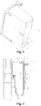
Fig. 1 is an exploded view of an electronic control assembly according to Embodiment 1 of the present invention. -
Fig. 2 is a structural diagram of an electronic control box assembly of the electronic control assembly according to Embodiment 1 of the present invention. -
Fig. 3 is a cross-sectional view of the electronic control assembly according to Embodiment 1 of the present invention. -
Fig. 4 is a partial enlarged view of the electronic control assembly at location IV inFig. 3 according to Embodiment 1 of the present invention. -
Fig. 5 is a structural diagram of a base of the electronic control assembly according to Embodiment 1 of the present invention. - List of serial numbers in the figures:
1 - Electronic control assembly; 2 - Base; 3 - Electronic control box assembly; 4 - Limiting member; 5 - Mounting member; 6 - Limit portion; 7 - Limit surface; 8 - First guide surface; 9 - Latching portion; 10 - First latching segment; 11 - Second latching segment; 12 - Abut portion; 13 - Abut surface; 14 - Second guide surface; 15 - Guide section; 16 - Limit section; 17 - Reset section; 18 - Snap portion; 19 - First section; 20 - Transition section; 21 - Second section; 23 - Electronic control box; 24 - Protection plate. - It should be noted that, in the case of no conflicts, the embodiments and features in the embodiments of the present invention can be combined mutually.
- The present invention is described in detail with reference to drawings and with combination of embodiments.
- With reference to
Fig. 1 , an electronic control assembly 1 is provided in this embodiment. The electronic control assembly 1 in this embodiment is easy to detach, which reduces the cost of the electronic control assembly 1. - In this embodiment, the electronic control assembly 1 includes a
base 2 and an electronic control box assembly 3, wherein a limitingmember 4 is disposed on the electronic control box assembly 3, amounting member 5 is disposed on thebase 2, and the limitingmember 4 cooperates with themounting member 5 to limit the electronic control box assembly 3 from moving relative to thebase 2 and to fix the electronic control box assembly 3 and thebase 2. - In this embodiment, the
limiting member 4 cooperates with themounting member 5 to limit the electronic control box assembly 3 from moving relative to thebase 2 and to fix the electronic control box assembly 3 and thebase 2. In this embodiment, the electronic control assembly 1 is easy to detach, which reduces the cost of the electronic control assembly 1. - With reference to
Fig. 2 , in this embodiment, thelimiting member 4 includes alimit portion 6, and thelimit portion 6 is disposed on one side of the electronic control box assembly 3. Thelimit portion 6 abuts against themounting surface 5 to limit a displacement of the electronic control box assembly 3 relative to thebase 2. - In this embodiment, the
limit portion 6 has a limit surface 7. After thelimit portion 6 slides into position relative to themounting member 5, the limit surface 7 abuts against themounting member 5 to limit a displacement of the electronic control box assembly 3 relative to thebase 2. - In this embodiment, the
limit portion 6 has aguide surface 8. After theguide surface 8 is slid into position relative to themounting member 5, the limit surface 7 abuts against themounting member 5. - In this embodiment, the
limit portion 6 is a triangular prism, and the triangular prism has three side surfaces and two end surfaces, wherein one side surface is connected to a side wall of the electronic control box assembly 3. In another two side surfaces, one side surface is theabut surface 13, and the other is thefirst guide surface 8. Both theabut surface 13 and thefirst guide surface 8 extend to the side wall of the electronic control box assembly 3. - In this embodiment, the
abut surface 13 is perpendicular to the side wall of the electronic control box assembly 3, and thefirst guide surface 8 is disposed at an acute angle with the side wall of the electronic control box assembly 3. - It should be noted that in this embodiment, the
abut surface 13 is perpendicular to the side wall of the electronic control box assembly 3, and thefirst guide surface 8 is disposed at an acute angle with the side wall of the electronic control box assembly 3. But this is not limited to this, in other embodiments of the present invention, theabut surface 13 is disposed at an acute angle with the side wall of the electronic control box assembly 3, thefirst guide surface 8 is perpendicular to the side wall of the electronic control box assembly 3, or both theabut surface 13 and thefirst guide surface 8 is disposed at an acute angle with the side wall of the electronic control box assembly 3. Any solutions equivalent to this embodiment that may achieve the effects of this embodiment is within the protection scope of the present invention. - In this embodiment, the limiting
member 4 further includes a latchingportion 9, and the latchingportion 9 is latched with the mountingmember 5 for fixing thebase 2 and the limitingmember 4. - In this embodiment, the latching
portion 9 is disposed at a bottom wall of the electronic box assembly 3 adjacent to thelimit portion 6. - In this embodiment, the latching
portion 9 includes afirst latching segment 10 and a second latching segment 11 that are connected to each other and are L-shaped. Thefirst latching segment 10 has one end connected to the electronic control box assembly 3, and the other end connected to the second latching segment 11. - In this embodiment, the second latching section 11 passes through the mounting
member 5, and thefirst latching section 10 and the second latching section 11 move relative to the mountingmember 5, so that thefirst latching section 10 abuts against the second latching section for fixing thebase 2 and the electronic box assembly 3. - In this embodiment, the electronic box assembly 3 includes an
electronic control box 23 and aprotection plate 24, wherein theprotection plate 24 is disposed outside theelectronic control box 23, and in this embodiment, thelimit portion 6 is disposed on theprotection plate 24. - It should be noted that in this embodiment, the electronic control box assembly 3 includes the
electronic control box 23 and theprotection plate 24, which is not limited herein. In other embodiments of the present invention, the electronic box assembly 3 may only include theelectronic control box 23, and thelimit portion 6 is disposed on theelectronic control box 23. Any solutions equivalent to this embodiment that may achieve the effects of this embodiment is within the protection scope of the present invention. - With reference to
Figs. 3 and4 , in this embodiment, anabut portion 12 is disposed on the mountingmember 5, and thelimit portion 6 abuts against theabut portion 12. Theabut portion 12 has anabut surface 13. After thelimit portion 6 is slid into position relative to theabut portion 12, the limit surface 7 abuts against theabut surface 13 to limit a displacement of the electronic control box assembly 3 relative to thebase 2. - In this embodiment, the
abut portion 12 has asecond guide surface 14. After thefirst guide surface 8 is slid into position relative to thesecond guide surface 14, the limit surface 7 abuts against theabut surface 13. - In this embodiment, when the second latching section 11 passes through the mounting
member 5 and moves relative to the mountingmember 5, thefirst guide surface 8 abuts against thesecond guide surface 14 and slides relative to thesecond guide surface 14. When thefirst guide surface 8 slides into position relative to thesecond guide surface 14, theabut surface 13 abuts against the limit surface 7 to limit a displacement of the electronic control box assembly 3 relative to thebase 2. - In this embodiment, the
first guide surface 8 abuts against thesecond guide surface 14 and slides relative to thesecond guide surface 14. When thefirst guide surface 8 slides relative to thesecond guide surface 14 to disengage from thesecond guide surface 14, indicating that thefirst guide surface 8 slides into position relative to thesecond guide surface 14. - In this embodiment, the
limit portion 6 includes aguide section 15 and alimit section 16, wherein theguide section 15 is connected to the mountingmember 5, thelimit section 16 is connected to one end of theguide section 15 away from the mountingmember 5 and disposed at an acute angle. The guide surface is disposed at one side of theguide section 15 away from thelimit section 16, and the limit surface 7 is disposed at one side of thelimit section 16 away from theguide section 15. - In this embodiment, the
limit portion 6 further includes areset section 17, and one end of thereset section 17 is connected to one end of thelimit section 16 away from theguide section 15. Thereset section 17 may drive thelimit section 16 and theguide section 15 to rotate, so that the limit surface 7 is released from abutment with theabut surface 13. - In this embodiment, when the electronic box assembly 3 is required to fix with the
base 2, the limit surface 7 abuts against theabut surface 13 after thefirst guide surface 8 slides into position relative to thesecond guide surface 14 to limit a displacement of the electronic control box assembly 3 relative to thebase 2. When disassembly is required, thereset section 17 is pushed, and thereset section 17 drives thelimit section 16 and theguide section 15 to move close to the electronic control box assembly 3 relative to thebase 2, so that theabut surface 13 is released from abutment with the limit surface 7, and the electronic control box assembly 3 is released from limit with thebase 2, so as to remove the electronic control box assembly 3. - With reference to
Fig. 5 , in this embodiment, asnap portion 18 is disposed on the mountingmember 5, and the latchingportion 9 is latched with thesnap portion 18. - In this embodiment, the
snap portion 18 is a snap hole, and the snap hole includes afirst section 19, atransition section 20, and asecond section 21. Thefirst section 19 is connected to thesecond section 21 through thetransition section 20, and a width of thefirst section 19 is larger than a width of thesecond section 21. - In this embodiment, the
transition section 20 is transitionally connected to thefirst section 19 and thesecond section 21. A width of thefirst section 19 is greater than a width of thesecond section 21. Thefirst section 19 is used as aguide section 15 and thesecond section 21 is a fixed section. After the second latching section 11 enters into thesecond section 21 through thetransition section 20 by the guide of thefirst section 19, the second latching section 11 abuts against a side wall of the mountingmember 5 to limit a displacement of the electronic control box assembly 3 in a direction perpendicular to the mountingmember 5, and thefirst latching section 10 abuts against thesecond section 21 for cooperating with thesecond section 21 to limit displacements of the electronic control box assembly 3 in three directions in a plane parallel to the mountingmember 5. Except for the direction in which thesecond section 21 is communicated with thefirst section 19, displacements in other directions are limited. - In this embodiment, the width of the
first section 19 is greater than the width of thesecond section 21, the second latching section 11 passes through thefirst section 19, and thefirst latching section 10 and the second latching section 11 move close to thesecond section 21. After thefirst latching section 10 and the second latching section 11 move to thesecond section 21, thefirst latching section 10 abuts against thesecond section 21 to fix the electronic box assembly 3. - In this embodiment, the
abut surface 13 is parallel to the opposite side walls of thefirst section 19 and thesecond section 21. Theabut surface 13 abuts against the limit surface 7, so that a displacement in a direction in which thefirst section 19 is communicated with thesecond section 21 is limited to fix the electronic control box assembly 3. - The working principle of the electronic control assembly 1 provided by the embodiment of the present invention is: in this embodiment, when the second latching section 11 moves close to the
second section 21 through the mountingmember 5 by thefirst section 19, thefirst guide surface 8 abuts against thesecond guide surface 14, and thefirst guide surface 8 slides relative to thesecond guide surface 14. After thefirst guide surface 8 slides into position relative to thesecond guide surface 14, theabut surface 13 abuts against the limit surface 7. And thefirst latching section 10 slides into a region where thesecond section 21 is located. - When the electronic control box assembly 3 is required to disassemble, the
reset section 17 is pushed, and thereset section 17 drives theguide section 15 and the abut section to move close to the electronic control box assembly 3 relative to thebase 2, so that theabut surface 13 is released from abutment with the limit surface 7. After theabut surface 13 is released from abutment with the limit surface 7, the electronic control box assembly 3 moves away from thesecond section 21, and the second latching section 11 is removed from thefirst section 19, so as to disassemble the electronic control box assembly 3. - In summary, the electronic control assembly 1 is this embodiment may limit the displacement of the electronic control box assembly 3 relative to the
base 2 for fixing the electronic control box assembly 3. In this embodiment, the electronic control box assembly 3 and thebase 2 are easy to disassemble, which reduces the cost of the electronic control assembly 1. - This embodiment provides an air conditioner (not shown). The air conditioner in this embodiment is easy to disassemble, which may reduce the cost of the air conditioner.
- For a brief description, reference may be made to the first embodiment for the places not mentioned in this embodiment.
- In this embodiment, the air conditioner includes the electronic control assembly 1 is the embodiments and a housing (air conditioner), wherein the
base 2 is connected to the housing.
Claims (10)
- An electronic control assembly, characterized in that, the electronic control assembly comprises a base (2) and an electronic control box assembly (3), wherein a limiting member (4) is disposed on the electronic control box assembly (3), a mounting member (5) is disposed on the base (2), and the limiting member (4) cooperates with the mounting member (5) to limit the electronic control box assembly (3) from moving relative to the base (2) and to fix the electronic control box assembly (3) and the base (2).
- The electronic control assembly according to claim 1, wherein the limiting member (4) comprises a limit portion (6), and the limit portion (6) is disposed on one side of the electronic control box assembly (3); an abut portion (12) is disposed on the mounting member (5), and the limit portion (6) abuts against the abut portion (12).
- The electronic control assembly according to claim 2, wherein the abut portion (12) comprises an abut surface (13), and the limit portion (6) comprises a limit surface (7); after the limit portion (6) slides into position relative to the abut portion (12), the limit surface (7) abuts against the abut surface (13) to limit a displacement of the electronic control box assembly (3) relative to the base (2).
- The electronic control assembly according to claim 3, wherein the limit portion (6) comprises a first guide surface (8), and the abut portion (12) comprises a second guide surface (14); after the first guide surface (8) slides into position relative to the second guide surface (14), the limit surface (7) abuts against the abut surface (13).
- The electronic control assembly according to claim 4, wherein the limit portion (6) comprises a guide section (15) and a limit section (16), the guide section (15) is connected to the mounting member (5), and the limit section (16) is connected to one end of the guide section (15) and is disposed at an acute angle; the second guide surface (14) is disposed on one side of the guide section (15) away from the limit section (16), and the limit surface (7) is disposed on one side of the limit section (16) away from the guide section (15).
- The electronic control assembly (1) according to claim 5, wherein the limit portion (6) further comprises a reset section (17), and one end of the reset section (17) is connected to one end of the limit section (16) away from the guide section (15); the reset section (17) drives the limit section (16) and the guide section (15) to rotate, so that the limit surface (7) is released from abutment with the abut surface (13).
- The electronic control assembly (1) according to claim 1, wherein the limiting member (4) comprises a latching portion (9), a snap portion (18) is disposed in the mounting member (5), and the latching portion (9) is latched with the snap portion (18).
- The electronic control assembly (1) according to claim 7, wherein the latching portion (9) comprises a first latching segment (10) and a second latching segment (11) that are connected to each other and are L-shaped; the first latching segment (10) has one end connected to the electronic control box assembly (3), and the other end connected to the second latching segment (11).
- The electronic control assembly (1) according to claim 7, wherein the snap portion (18) is a snap hole, and the snap hole comprises a first section (19), a transition section (20), and a second section (21); the first section (19) is connected to the second section (21) through the transition section (20), and a width of the first section (19) is larger than a width of the second section (21).
- An air conditioner, characterized in that, the comprises air conditioner the electronic control assembly (1) according to any one of claims 1 to 9.
Applications Claiming Priority (2)
| Application Number | Priority Date | Filing Date | Title |
|---|---|---|---|
| CN201820060319.7U CN207741276U (en) | 2018-01-15 | 2018-01-15 | A kind of electrically-controlled component and air-conditioning |
| PCT/CN2018/125494 WO2019137260A1 (en) | 2018-01-15 | 2018-12-29 | Electronic control assembly and air conditioner |
Publications (2)
| Publication Number | Publication Date |
|---|---|
| EP3742065A1 true EP3742065A1 (en) | 2020-11-25 |
| EP3742065A4 EP3742065A4 (en) | 2021-10-06 |
Family
ID=63123177
Family Applications (1)
| Application Number | Title | Priority Date | Filing Date |
|---|---|---|---|
| EP18900031.8A Withdrawn EP3742065A4 (en) | 2018-01-15 | 2018-12-29 | Electronic control assembly and air conditioner |
Country Status (6)
| Country | Link |
|---|---|
| EP (1) | EP3742065A4 (en) |
| JP (1) | JP7045452B2 (en) |
| CN (1) | CN207741276U (en) |
| AU (1) | AU2018401188B2 (en) |
| NZ (1) | NZ765678A (en) |
| WO (1) | WO2019137260A1 (en) |
Families Citing this family (3)
| Publication number | Priority date | Publication date | Assignee | Title |
|---|---|---|---|---|
| CN207741276U (en) * | 2018-01-15 | 2018-08-17 | 奥克斯空调股份有限公司 | A kind of electrically-controlled component and air-conditioning |
| CN109959132A (en) * | 2019-04-22 | 2019-07-02 | 宁波奥克斯电气股份有限公司 | A kind of automatically controlled box mounting structure and air conditioner |
| US20220412600A1 (en) * | 2019-12-31 | 2022-12-29 | Gd Midea Air-Conditioning Equipment Co., Ltd. | Air conditioner |
Family Cites Families (13)
| Publication number | Priority date | Publication date | Assignee | Title |
|---|---|---|---|---|
| DE3034007A1 (en) * | 1980-09-10 | 1982-04-15 | Walter Ing.(Grad.) 7000 Stuttgart Dreizler | Mechanically drive room air-conditioning flap - has electric control for driving motor on strip across inner tube, with mounting angle of 30 degrees |
| KR100389429B1 (en) | 2001-06-19 | 2003-06-27 | 주식회사 엘지이아이 | A control box mounting structure for air conditioner |
| JP3841067B2 (en) | 2003-06-25 | 2006-11-01 | ダイキン工業株式会社 | Air conditioner indoor unit electrical unit |
| KR100680621B1 (en) | 2005-10-27 | 2007-02-08 | 삼성전자주식회사 | Air conditioner |
| EP1953461A1 (en) * | 2007-01-26 | 2008-08-06 | LG Electronics Inc. | Indoor unit of an air conditioner with moving front panels to suck air from a front and discharge air vertically |
| JP5317915B2 (en) | 2009-09-29 | 2013-10-16 | 三菱電機株式会社 | Air conditioner |
| JP5317920B2 (en) | 2009-10-13 | 2013-10-16 | 三菱電機株式会社 | Remote control transceiver and air conditioner equipped with the same |
| CN204494640U (en) * | 2015-02-09 | 2015-07-22 | 广东美的暖通设备有限公司 | Electric-controlled box and air-conditioner |
| CN205842855U (en) * | 2016-06-25 | 2016-12-28 | 宁波奥克斯空调有限公司 | Air-conditioning indoor hanging unit |
| CN206073295U (en) * | 2016-09-22 | 2017-04-05 | 江苏新科电器有限公司 | Hanging type indoor machine base |
| CN206469429U (en) * | 2016-11-28 | 2017-09-05 | 广东美的暖通设备有限公司 | Air conditioner |
| CN107518854A (en) * | 2017-08-08 | 2017-12-29 | 佛山市顺德区美的洗涤电器制造有限公司 | Electric-controlled box and dish-washing machine |
| CN207741276U (en) * | 2018-01-15 | 2018-08-17 | 奥克斯空调股份有限公司 | A kind of electrically-controlled component and air-conditioning |
-
2018
- 2018-01-15 CN CN201820060319.7U patent/CN207741276U/en active Active
- 2018-12-29 EP EP18900031.8A patent/EP3742065A4/en not_active Withdrawn
- 2018-12-29 NZ NZ765678A patent/NZ765678A/en not_active IP Right Cessation
- 2018-12-29 JP JP2020524410A patent/JP7045452B2/en active Active
- 2018-12-29 WO PCT/CN2018/125494 patent/WO2019137260A1/en unknown
- 2018-12-29 AU AU2018401188A patent/AU2018401188B2/en active Active
Also Published As
| Publication number | Publication date |
|---|---|
| WO2019137260A1 (en) | 2019-07-18 |
| JP2021503174A (en) | 2021-02-04 |
| CN207741276U (en) | 2018-08-17 |
| JP7045452B2 (en) | 2022-03-31 |
| AU2018401188B2 (en) | 2022-01-13 |
| NZ765678A (en) | 2022-05-27 |
| AU2018401188A1 (en) | 2020-04-02 |
| EP3742065A4 (en) | 2021-10-06 |
Similar Documents
| Publication | Publication Date | Title |
|---|---|---|
| EP3742065A1 (en) | Electronic control assembly and air conditioner | |
| US10036561B2 (en) | Indoor unit for air conditioner | |
| US7839629B2 (en) | Fixture for a disk drive | |
| WO2019047729A1 (en) | Air conditioner and heat-exchange system having same | |
| US20070284981A1 (en) | Slide rail structure for industry-used computers | |
| CN102759962A (en) | Computer shell with wind scooper | |
| CN106440107B (en) | Air conditioner | |
| CN113790198B (en) | Sliding structure, mounting method, and actuator | |
| WO2020216102A1 (en) | Evaporator fixing structure and air conditioner | |
| CN208312590U (en) | Air exhausting structure and window air conditioner with it | |
| CN208430638U (en) | Plain splice structure for integral bathroom sheet wall | |
| CN103032823B (en) | Stage lamplight cutting system convenient for positioning | |
| CN219955487U (en) | Air deflector driving mechanism and air conditioner | |
| WO2019047730A1 (en) | Air conditioner and heat-exchange system having same | |
| CN216143813U (en) | Air conditioner indoor unit and air conditioner | |
| CN219367776U (en) | Indoor unit of air conditioner and air conditioner | |
| CN219718844U (en) | Regulator convenient to installation | |
| US20230258364A1 (en) | Drive mechanism and air conditioner | |
| CN215909375U (en) | Flow guide structure and air conditioner with same | |
| CN220471749U (en) | Air deflector assembly and air conditioner | |
| CN210954842U (en) | Notebook computer shell convenient to dismouting | |
| TWI819799B (en) | Case | |
| CN221040742U (en) | Reactor assembly and air conditioner | |
| CN218934936U (en) | Board inserting structure | |
| CN217669044U (en) | Simple tool for assembling rotor of electric air compressor |
Legal Events
| Date | Code | Title | Description |
|---|---|---|---|
| STAA | Information on the status of an ep patent application or granted ep patent |
Free format text: STATUS: THE INTERNATIONAL PUBLICATION HAS BEEN MADE |
|
| PUAI | Public reference made under article 153(3) epc to a published international application that has entered the european phase |
Free format text: ORIGINAL CODE: 0009012 |
|
| STAA | Information on the status of an ep patent application or granted ep patent |
Free format text: STATUS: REQUEST FOR EXAMINATION WAS MADE |
|
| 17P | Request for examination filed |
Effective date: 20200323 |
|
| AK | Designated contracting states |
Kind code of ref document: A1 Designated state(s): AL AT BE BG CH CY CZ DE DK EE ES FI FR GB GR HR HU IE IS IT LI LT LU LV MC MK MT NL NO PL PT RO RS SE SI SK SM TR |
|
| AX | Request for extension of the european patent |
Extension state: BA ME |
|
| DAV | Request for validation of the european patent (deleted) | ||
| DAX | Request for extension of the european patent (deleted) | ||
| A4 | Supplementary search report drawn up and despatched |
Effective date: 20210903 |
|
| RIC1 | Information provided on ipc code assigned before grant |
Ipc: F24F 13/20 20060101ALI20210827BHEP Ipc: F24F 13/00 20060101ALI20210827BHEP Ipc: F24F 11/89 20180101AFI20210827BHEP |
|
| STAA | Information on the status of an ep patent application or granted ep patent |
Free format text: STATUS: THE APPLICATION IS DEEMED TO BE WITHDRAWN |
|
| 18D | Application deemed to be withdrawn |
Effective date: 20220402 |