US10769824B2 - Method for defining drawing planes for the design of a 3D object - Google Patents
Method for defining drawing planes for the design of a 3D object Download PDFInfo
- Publication number
- US10769824B2 US10769824B2 US16/225,180 US201816225180A US10769824B2 US 10769824 B2 US10769824 B2 US 10769824B2 US 201816225180 A US201816225180 A US 201816225180A US 10769824 B2 US10769824 B2 US 10769824B2
- Authority
- US
- United States
- Prior art keywords
- plane
- virtual camera
- pose
- current drawing
- viewing frustum
- Prior art date
- Legal status (The legal status is an assumption and is not a legal conclusion. Google has not performed a legal analysis and makes no representation as to the accuracy of the status listed.)
- Active, expires
Links
- 238000000034 method Methods 0.000 title claims abstract description 42
- 238000013461 design Methods 0.000 title description 6
- 230000004044 response Effects 0.000 claims abstract description 8
- 230000004913 activation Effects 0.000 claims description 16
- 230000000007 visual effect Effects 0.000 claims description 7
- 238000013500 data storage Methods 0.000 claims description 4
- 238000004590 computer program Methods 0.000 claims description 3
- 238000012360 testing method Methods 0.000 description 10
- 230000008859 change Effects 0.000 description 6
- 230000008569 process Effects 0.000 description 6
- 238000013519 translation Methods 0.000 description 3
- 230000014616 translation Effects 0.000 description 3
- 239000013598 vector Substances 0.000 description 3
- 101000854862 Homo sapiens Vacuolar protein sorting-associated protein 35 Proteins 0.000 description 2
- 102100020822 Vacuolar protein sorting-associated protein 35 Human genes 0.000 description 2
- 230000001413 cellular effect Effects 0.000 description 2
- 238000004891 communication Methods 0.000 description 2
- 239000013256 coordination polymer Substances 0.000 description 2
- 238000010586 diagram Methods 0.000 description 2
- 238000006073 displacement reaction Methods 0.000 description 2
- 230000006870 function Effects 0.000 description 2
- 238000012545 processing Methods 0.000 description 2
- 101000666896 Homo sapiens V-type immunoglobulin domain-containing suppressor of T-cell activation Proteins 0.000 description 1
- 241001422033 Thestylus Species 0.000 description 1
- 102100038282 V-type immunoglobulin domain-containing suppressor of T-cell activation Human genes 0.000 description 1
- 238000012938 design process Methods 0.000 description 1
- 238000001514 detection method Methods 0.000 description 1
- 238000000802 evaporation-induced self-assembly Methods 0.000 description 1
- IJJVMEJXYNJXOJ-UHFFFAOYSA-N fluquinconazole Chemical compound C=1C=C(Cl)C=C(Cl)C=1N1C(=O)C2=CC(F)=CC=C2N=C1N1C=NC=N1 IJJVMEJXYNJXOJ-UHFFFAOYSA-N 0.000 description 1
- 230000010365 information processing Effects 0.000 description 1
- 230000003993 interaction Effects 0.000 description 1
- 238000009877 rendering Methods 0.000 description 1
- 238000012552 review Methods 0.000 description 1
- 239000007787 solid Substances 0.000 description 1
Images


Classifications
-
- G—PHYSICS
- G06—COMPUTING; CALCULATING OR COUNTING
- G06T—IMAGE DATA PROCESSING OR GENERATION, IN GENERAL
- G06T11/00—2D [Two Dimensional] image generation
- G06T11/20—Drawing from basic elements, e.g. lines or circles
- G06T11/203—Drawing of straight lines or curves
-
- G—PHYSICS
- G06—COMPUTING; CALCULATING OR COUNTING
- G06T—IMAGE DATA PROCESSING OR GENERATION, IN GENERAL
- G06T11/00—2D [Two Dimensional] image generation
- G06T11/001—Texturing; Colouring; Generation of texture or colour
-
- G—PHYSICS
- G06—COMPUTING; CALCULATING OR COUNTING
- G06F—ELECTRIC DIGITAL DATA PROCESSING
- G06F30/00—Computer-aided design [CAD]
-
- G—PHYSICS
- G06—COMPUTING; CALCULATING OR COUNTING
- G06T—IMAGE DATA PROCESSING OR GENERATION, IN GENERAL
- G06T11/00—2D [Two Dimensional] image generation
- G06T11/20—Drawing from basic elements, e.g. lines or circles
-
- G—PHYSICS
- G06—COMPUTING; CALCULATING OR COUNTING
- G06T—IMAGE DATA PROCESSING OR GENERATION, IN GENERAL
- G06T17/00—Three dimensional [3D] modelling, e.g. data description of 3D objects
-
- G—PHYSICS
- G06—COMPUTING; CALCULATING OR COUNTING
- G06T—IMAGE DATA PROCESSING OR GENERATION, IN GENERAL
- G06T17/00—Three dimensional [3D] modelling, e.g. data description of 3D objects
- G06T17/10—Constructive solid geometry [CSG] using solid primitives, e.g. cylinders, cubes
-
- G—PHYSICS
- G06—COMPUTING; CALCULATING OR COUNTING
- G06T—IMAGE DATA PROCESSING OR GENERATION, IN GENERAL
- G06T19/00—Manipulating 3D models or images for computer graphics
- G06T19/20—Editing of 3D images, e.g. changing shapes or colours, aligning objects or positioning parts
-
- G—PHYSICS
- G06—COMPUTING; CALCULATING OR COUNTING
- G06T—IMAGE DATA PROCESSING OR GENERATION, IN GENERAL
- G06T2219/00—Indexing scheme for manipulating 3D models or images for computer graphics
- G06T2219/20—Indexing scheme for editing of 3D models
- G06T2219/2016—Rotation, translation, scaling
-
- G—PHYSICS
- G06—COMPUTING; CALCULATING OR COUNTING
- G06T—IMAGE DATA PROCESSING OR GENERATION, IN GENERAL
- G06T2219/00—Indexing scheme for manipulating 3D models or images for computer graphics
- G06T2219/20—Indexing scheme for editing of 3D models
- G06T2219/2021—Shape modification
Definitions
- the invention relates to the field of computers programs and systems, and more specifically to the field of computer-implemented methods for designing and drawing a three-dimensional (3D) modeled object in a 3D scene.
- the present invention belongs to the field of the design of 3D objects (sketching, modeling, review, CAD . . . ).
- the present invention belongs to the sketching field, in which a software product such as Natural Sketch, provided by Dassault Systèmes, can be used. With some strokes (using for example a tablet and a stylus, or a mouse) the user/designer gets the full 3D curves of his sketch. Then he can easily modify these curves until reaching the concept he imagined. Thus, the user does not need to wait for the step of 3D modeling to have a 3D rendering of his drawing.
- Natural Sketch One of the functions of a product such as Natural Sketch is to allow the user to draw 3D models.
- the user has different possibilities. For example, in the scene, there can be a surface (a car, a sphere . . . ) on which the user will draw. As the surface is in three dimensions, the curves on the surface will be 3D curves. But when the user has no surface on which he can rely on, i.e. when he wants to create a 3D model from scratch, he needs to proceed otherwise.
- the user switches from a drawing command button to a plane selection command button, and vice versa, until all the planes are defined.
- a drawing command button e.g. the xz plane.
- the user can start to draw on a default plane (e.g. the xz plane). If the user wants to start to draw on a plane which is different from the default plane, he can also press the plane selection command button.
- a plane manipulator square-shaped in Natural Sketch
- the pointing element a cursor
- the edge is highlighted.
- the drawing plane can then be rotated around an axis which passes through the center of the plane manipulator, and which is parallel to the highlighted edge.
- the user can change the drawing plane, according to the angle which is selected during the moving of the mouse. He can also change the origin of the drawing plane. For that, the user moves the pointing element on a central square of the plane manipulator which is located inside the square-shaped plane manipulator. A visual feedback, such as a highlighting of the central square, occurs, when the pointing element is moved in the central square. Then, the user can translate the origin of the drawing plane along the normal of the plane of the central square, while pressing the left button of the mouse. After that, the user can press (e.g.
- the drawing command button with the left-button of the mouse or with a stylus/finger
- sketches e.g. with the left-button of the mouse or with a stylus/finger
- the user wants to change the drawing plane, he has to press again the plane selection command button so as to use the plane manipulator.
- the user can navigate in the three-dimensional scene in order to change the viewpoint, by using, for example, a combination of moving the mouse while pressing the middle button of the mouse.
- a goal of the invention is then to provide an intuitive method for defining planes in a 3D scene, and drawing a 3D object on the defined planes, without requiring the execution of a specific command, and which lowers also the distance traveled by the mouse during the drawing process.
- a computer-implemented method for drawing a 3D object said 3D object being rendered in a 3D scene on a computer screen through a virtual camera, the method comprising the steps of:
- a computer system comprising a processor coupled to a memory and a graphical user interface, the memory storing computer-executable instructions to cause the computer system to carry out the predefined method.
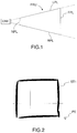
- FIG. 1 illustrates an example of a viewing frustum
- FIGS. 2 to 7 illustrates an example of a method for drawing a 3D object in a 3D scene according to the invention
- FIG. 8 illustrates a flowchart of the different steps of a method according to the invention.
- FIGS. 9 and 10 illustrate block diagrams of respective computer systems suitable for carrying out a method according to different embodiments of the invention.
- FIG. 1 is a top view of a viewing frustum FRU.
- the viewing frustum FRU is a truncated pyramid.
- the planes which cut the viewing frustum perpendicular to the viewing direction of the virtual camera are called the “near plane” NPL and the “far plane” FPL.
- the viewing frustum is bounded by the near plane NPL on the side of the virtual camera CAM and by the far plane FPL on the opposite side.
- the viewing frustum is also bounded by a left plane LPL, a right plane RPL, a top plane (not represented) and a bottom plane (not represented).
- the “pose” (also referred as the viewpoint) of the virtual camera refers to its position and its orientation in relation to a fixed reference frame on the scene.
- a plane is defined by two main non collinear vectors ( ⁇ right arrow over (u) ⁇ , ⁇ right arrow over (v) ⁇ ) and one origin (O).
- the origin of a plane is a 3D point, through which the plane passes.
- the normal n of the plane is easily got back by doing a vector product of ⁇ right arrow over (u) ⁇ and ⁇ right arrow over (v) ⁇ .
- two parallel and disjoint planes (P 1 , P 2 ) are characterized by the same main non collinear vectors ( ⁇ right arrow over (u) ⁇ , ⁇ right arrow over (y) ⁇ ), with different origins.
- the origin of the plane P 2 results from the projection of the origin of the plane P 1 on the plane P 2 .
- the origin of a plane refers to its “depth” in the 3D scene.
- FIG. 2 illustrates a first step of the invention.
- the user starts to draw a first stroke ST 1 in an initial plane.
- the initial plane is orthogonal to a second plane (PL 2 ) and to a third plane (PL 3 ).
- the initial plane is a default plane, or a previously defined plane.
- the user employs a sketching input.
- the sketching input can be the left button of the mouse, a stylus or a finger in touch mode.
- the first stroke ST 1 is sketched.
- the user can draw several first strokes ST 1 in the same initial plane, if he releases the sketching input between two first strokes ST 1 .
- the first strokes ST 1 represent nearly a square.
- the first strokes ST 1 are rendered in a first viewing frustum corresponding to a first pose of the virtual camera.
- the user can interact with a pointing element PE, so as to switch from the first pose to a second pose of the virtual camera.
- the interaction with the pointing element PE can be made through a dragging operation. This operation can be made for example with a combination of moving the mouse while pressing and holding the middle button of the mouse, or while pressing and holding the middle button of the mouse and the left button of the mouse, or while pressing and holding a keyboard button.
- the pose of the virtual camera is switched.
- the first strokes ST 1 are rendered according to a second viewing frustum, which corresponds to a second pose of the virtual camera.
- the inventors have found that the planes which are chosen to design and draw a 3D model are often orthogonal. They have also found that, most of the times, the user's strokes are performed in planes which are close to the near plane. Indeed, drawing on a plane which is far from the near plane would substantially distort the proportions of the drawing. For example, trying to draw a circle in a plane which is almost orthogonal to the near plane is very difficult, (it results generally in an ellipse), whereas the operation is easier in a plane which is almost parallel to the near plane. Consequently, the selection of the drawing planes relies on these two postulates.
- the normal of the near plane of the second viewing frustum is computed as soon as the user releases the middle button of the mouse.
- the normal of the near plane is compared with the normal of the first (PL 1 ), second (PL 2 ) and third planes (PL 3 ).
- the comparison can be made by computing the scalar product of the normal of the near plane and the normal of each of the first (PL 1 ), second (PL 2 ) and third planes (PL 3 ).
- the scalar product of the plane and the normal of the screen plane is computed. The one which has a maximum scalar product absolute value is considered as the closest to the near plane.
- the closest plane is then considered as the current drawing plane.
- the normal of the screen plane of the second viewing frustum is compared to the normal of the first (PL 1 ), second (PL 2 ) and third planes. Then, the closeness of the first (PL 1 ), second (PL 2 ) and third planes with the screen plane is computed on the fly.
- the user sketches second strokes ST 2 in the current drawing plane, as rendered in the second viewing frustum.
- the plane of the first strokes ST 1 and the plane of the second strokes ST 2 are orthogonal, even though the near plane of the first viewing frustum and the plane of the second viewing frustum are not necessarily orthogonal.
- the origin OR of the current drawing plane is computed based on the last sketched first stroke ST 1 in the first plane.
- the extremity of the last sketched first stroke ST 1 in the first plane which is closest to the near plane of the second viewing frustum defines the origin OR of the current drawing plane. Therefore, the user moves the pointing element PE close to the strokes ST 1 he has already made in the first plane in order to start the next one in the current drawing plane. The user also moves the pointing element PE close to where the first plane and the current drawing plane are intersecting. Indeed, once the user has completed a series of strokes (first strokes ST 1 ) in a first plane, he may change the pose of the virtual camera, in order to continue, with nearly no interruption, in the current drawing plane, the design of the 3D object (with second strokes ST 2 ).
- He may continue the design of the 3D object in the current drawing plane, starting from the closest extremity of the last strokes of the preceding plane. For that, the distance between the virtual camera and a first extremity of the last sketched first stroke ST 1 is compared to the distance between the virtual camera and a second extremity of the last sketched first stroke ST 1 .
- the computing of the distance between the virtual camera and a point in the 3D scene is known for the skilled person.
- the extremity corresponding to the closest distance is defined as the origin of the current drawing plane.
- the user can modify the origin OR of the current drawing plane, so as to select the “depth” of the drawing plane. Consequently, the user can design the 3D object on parallel planes in an almost uninterrupted design process. For that, he uses an activation input designating a 3D point of one of the strokes (ST 1 , ST 2 ) of the 3D scene. To do so, the user presses and holds an activation button, while moving the pointing element PE with the mouse (without pressing a mouse button) in the 3D scene along one of the sketched strokes (ST 1 , ST 2 ).
- the activation button can be for example a keyboard button, more precisely the “CTRL” button of the keyboard.
- the setting of the origin OR is performed as long as the user presses and holds the activation button.
- the origin of the current drawing plane is finally determined when the user releases the activation button.
- the user can designate a first stroke ST 1 which is sketched only in the first plane.
- a visual feedback can be progressively generated on all the first strokes ST 1 of the first plane PL 1 , according to the displacement of the pointing element PE along the first stroke ST 1 . Therefore, in order to sketch the next stroke in a parallel plane, the user naturally moves the pointing element PE near the strokes he has already sketched, which avoids useless mouse movements. He also intuitively moves the pointing element PE close to the intersection of the drawing planes which have already been defined, thereby also saving mouse movements.
- FIG. 7 illustrates, with another pose of the virtual camera, the 3D object which has been drawn.
- a visual feedback of the current drawing plane i.e. whose normal is the closest to the normal of the near plane, can be provided.
- a highlighting of the strokes of the current drawing plane can be performed, so that the user instantly sees on which planes he is going to draw.
- FIG. 8 is represented a flow-chart of a method according to the invention.
- a test 101 is made to check if the user is drawing. If the user is drawing, i.e. as long as a sketching input is detected, the drawing plane remains unchanged (step 102 ). If he is not drawing, a test 103 is made to check if the pose of the virtual camera is being changed. Thus, a test of detection of the pressing of the middle button (optionally with left button) of the mouse is being made. A new drawing plane is then computed at step 104 . Then, a test 105 is made to check if the drawing plane has changed.
- the origin of the drawing plane is computed, based on the distance of each of the extremities to the virtual camera (step 106 ). If the test is negative, the user continues to draw in the same plane (step 107 ). If the test 103 is negative, a test 108 is made to detect an activation input of the setting of the origin (for example if the pressing of a keyboard button, especially the CTRL button, is detected). If the test is affirmative, a new origin is set (step 109 ). If the test is negative, the user continues to draw in the same plane as initially (step 110 ).
- the user does not need to break his creation process to translate or rotate a plane until he reaches a precise location.
- the inventive method can be performed by a suitably-programmed general-purpose computer or computer system, possibly including a computer network, storing a suitable program in non-volatile form on a computer-readable medium such as a hard disk, a solid state disk or a CD-ROM and executing said program using its microprocessor(s) and memory.
- a suitably-programmed general-purpose computer or computer system possibly including a computer network, storing a suitable program in non-volatile form on a computer-readable medium such as a hard disk, a solid state disk or a CD-ROM and executing said program using its microprocessor(s) and memory.
- FIG. 9 A computer suitable for carrying out a method according to an exemplary embodiment of the present invention is described with reference to FIG. 9 .
- the computer includes a Central Processing Unit (CPU) CP which performs the method step described above while running an executable program, i.e. a set of computer-readable instructions, stored in a memory device such as RAM MEM 1 or ROM MEM 2 or hard disk drive (HDD) MEM 3 , DVD/CD drive MEM 4 , or stored remotely.
- an executable program i.e. a set of computer-readable instructions
- RAM MEM 1 or ROM MEM 2 or hard disk drive (HDD) MEM 3 , DVD/CD drive MEM 4 or stored remotely.
- one or more computer files defining the three-dimensional object may also be stored on one or more of memory devices MEM 1 to MEM 4 , or remotely.
- the claimed invention is not limited by the form of the computer-readable media on which the computer-readable instructions of the inventive process are stored.
- the instructions and files can be stored on CDs, DVDs, in FLASH memory, RAM, ROM, PROM, EPROM, EEPROM, hard disk or any other information processing device with which the computer communicates, such as a server or computer.
- the program can be stored on a same memory device or on different memory devices.
- a computer program suitable for carrying out the inventive method can be provided as a utility application, background daemon, or component of an operating system, or combination thereof, executing in conjunction with CPU P and an operating system such as Microsoft VISTA, Microsoft Windows 8, UNIX, Solaris, LINUX, Apple MAC-OS and other systems known to those skilled in the art.
- an operating system such as Microsoft VISTA, Microsoft Windows 8, UNIX, Solaris, LINUX, Apple MAC-OS and other systems known to those skilled in the art.
- CPU CP can be a XeonTM processor from Intel of America or an OpteronTM processor from AMD of America, or can be other processor types, such as a Freescale ColdFireTM, IMXTM, or jJJTM processor from Freescale Corporation of America.
- the CPU can be a processor such as a Core2 Duo from Intel Corporation of America, or can be implemented on an FPGA, ASIC, PLD or using discrete logic circuits, as one of ordinary skill in the art would recognize.
- the CPU can be implemented as multiple processors cooperatively working to perform the computer-readable instructions of the inventive processes described above.
- the computer in FIG. 9 also includes a network interface NI, such as an Intel Ethernet PRO network interface card from Intel Corporation of America, for interfacing with a network, such as a local area network (LAN), wide area network (WAN), the Internet and the like.
- the computer further includes a display controller DC, such as a NVIDIA GeForceTM GTX graphics adaptor from NVIDIA Corporation of America for interfacing with display DY, such as a Hewlett Packard HPL2445w LCD monitor.
- a general purpose I/O interface IF interfaces with a keyboard KB and pointing device PD, such as a roller ball, mouse, touchpad and the like.
- a graphical user interface used by the user to provide input commands—e.g. to move the pointer—and by the computer for displaying the three-dimensional scene and the graphical tool.
- Disk controller DKC connects HDD MEM 3 and DVD/CD MEM 4 with communication bus CBS, which can be an ISA, EISA, VESA, PCI, or similar, for interconnecting all of the components of the computer.
- CBS can be an ISA, EISA, VESA, PCI, or similar, for interconnecting all of the components of the computer.
- FIG. 10 is a block diagram of a computer system suitable for carrying out a method according to a different exemplary embodiment of the present invention.
- the executable program EXP and the computer files defining the three-dimensional object are stored on memory devices connected to a server SC.
- the memory devices and the overall architecture of the server may be the same as discussed above with reference to FIG. 9 , except that display controller, sensitive surface, display, keyboard and/or pointing device may be missing in the server.
- the server SC is then connected to an administrator system ADS and end user computer EUC via a network NW.
- the overall architectures of the administrator system and of the end user computer may be the same as discussed above with reference to FIG. 9 , except that the memory devices of the administrator system and the end user computer do not store the executable program EXP and/or the computer files defining the three-dimensional object. However, the end user computer does store a client program designed for cooperating with the executable program of the server, as it will be discussed below.
- the network NW can be a public network, such as the Internet, or a private network such as an LAN or WAN network, or any combination thereof and can also include PSTN or ISDN sub-networks.
- the network NW can also be wired, such as an Ethernet network, or can be wireless such as a cellular network including EDGE, 3G and 4G wireless cellular systems.
- the wireless network can also be Wi-Fi, Bluetooth, or any other wireless form of communication that is known.
- the network NW is merely exemplary and in no way limits the scope of the present advancements.
- the client program stored in a memory device of the end user computer and executed by a CPU of the latter accesses, via the network NW, a database DB stored by the server SC and containing files defining three-dimensional object.
- the server performs the processing as described above, and transmits to the end user computer an image file corresponding to the desired representation of the scene including the 3D object, again using the network NW.
Landscapes
- Engineering & Computer Science (AREA)
- Physics & Mathematics (AREA)
- Theoretical Computer Science (AREA)
- General Physics & Mathematics (AREA)
- Geometry (AREA)
- Software Systems (AREA)
- Computer Graphics (AREA)
- Computer Hardware Design (AREA)
- General Engineering & Computer Science (AREA)
- Architecture (AREA)
- Evolutionary Computation (AREA)
- Processing Or Creating Images (AREA)
- User Interface Of Digital Computer (AREA)
- Image Generation (AREA)
Applications Claiming Priority (3)
| Application Number | Priority Date | Filing Date | Title |
|---|---|---|---|
| EP17306969.1 | 2017-12-28 | ||
| EP17306969.1A EP3506214A1 (en) | 2017-12-28 | 2017-12-28 | Method for defining drawing planes for the design of a 3d object |
| EP17306969 | 2017-12-28 |
Publications (2)
| Publication Number | Publication Date |
|---|---|
| US20190206098A1 US20190206098A1 (en) | 2019-07-04 |
| US10769824B2 true US10769824B2 (en) | 2020-09-08 |
Family
ID=61002812
Family Applications (1)
| Application Number | Title | Priority Date | Filing Date |
|---|---|---|---|
| US16/225,180 Active 2038-12-21 US10769824B2 (en) | 2017-12-28 | 2018-12-19 | Method for defining drawing planes for the design of a 3D object |
Country Status (4)
| Country | Link |
|---|---|
| US (1) | US10769824B2 (ja) |
| EP (1) | EP3506214A1 (ja) |
| JP (1) | JP7340927B2 (ja) |
| CN (1) | CN110060328B (ja) |
Families Citing this family (3)
| Publication number | Priority date | Publication date | Assignee | Title |
|---|---|---|---|---|
| JP7248900B2 (ja) * | 2019-06-28 | 2023-03-30 | サミー株式会社 | 弾球遊技機 |
| JP7248903B2 (ja) * | 2019-06-28 | 2023-03-30 | サミー株式会社 | 弾球遊技機 |
| CN113496049B (zh) * | 2020-04-03 | 2024-03-12 | 琦境科技(北京)有限公司 | 一种三维空间物品规划的方法和系统 |
Citations (7)
| Publication number | Priority date | Publication date | Assignee | Title |
|---|---|---|---|---|
| US5459821A (en) * | 1991-11-07 | 1995-10-17 | International Business Machines Corporation | Method and apparatus for generating a free-form surface |
| US20040247174A1 (en) * | 2000-01-20 | 2004-12-09 | Canon Kabushiki Kaisha | Image processing apparatus |
| US20070080960A1 (en) * | 2005-10-06 | 2007-04-12 | Alias Systems Corp. | Workflow system for 3D model creation |
| US20080036773A1 (en) * | 2006-02-21 | 2008-02-14 | Seok-Hyung Bae | Pen-based 3d drawing system with 3d orthographic plane or orthrographic ruled surface drawing |
| US20120162258A1 (en) * | 2010-01-11 | 2012-06-28 | Olaworks, Inc. | Method, system, and computer-readable recording medium for providing information on an object using viewing frustums |
| EP2889738A1 (en) | 2013-12-30 | 2015-07-01 | Dassault Systèmes | Computer-implemented method for designing a three-dimensional modeled object |
| EP3179451A1 (en) | 2015-12-08 | 2017-06-14 | Dassault Systèmes | A computer-implemented method for drawing a polyline in a three-dimensional scene |
Family Cites Families (4)
| Publication number | Priority date | Publication date | Assignee | Title |
|---|---|---|---|---|
| JP2955989B2 (ja) * | 1997-02-18 | 1999-10-04 | 株式会社セガ・エンタープライゼス | ゲーム装置 |
| US7883415B2 (en) * | 2003-09-15 | 2011-02-08 | Sony Computer Entertainment Inc. | Method and apparatus for adjusting a view of a scene being displayed according to tracked head motion |
| JP2009075739A (ja) * | 2007-09-19 | 2009-04-09 | Namco Bandai Games Inc | プログラム、情報記憶媒体、および画像生成システム |
| JP2013125487A (ja) * | 2011-12-16 | 2013-06-24 | Konica Minolta Business Technologies Inc | 空間手書きシステム及び電子ペン |
-
2017
- 2017-12-28 EP EP17306969.1A patent/EP3506214A1/en active Pending
-
2018
- 2018-12-19 US US16/225,180 patent/US10769824B2/en active Active
- 2018-12-25 JP JP2018241416A patent/JP7340927B2/ja active Active
- 2018-12-27 CN CN201811610225.3A patent/CN110060328B/zh active Active
Patent Citations (7)
| Publication number | Priority date | Publication date | Assignee | Title |
|---|---|---|---|---|
| US5459821A (en) * | 1991-11-07 | 1995-10-17 | International Business Machines Corporation | Method and apparatus for generating a free-form surface |
| US20040247174A1 (en) * | 2000-01-20 | 2004-12-09 | Canon Kabushiki Kaisha | Image processing apparatus |
| US20070080960A1 (en) * | 2005-10-06 | 2007-04-12 | Alias Systems Corp. | Workflow system for 3D model creation |
| US20080036773A1 (en) * | 2006-02-21 | 2008-02-14 | Seok-Hyung Bae | Pen-based 3d drawing system with 3d orthographic plane or orthrographic ruled surface drawing |
| US20120162258A1 (en) * | 2010-01-11 | 2012-06-28 | Olaworks, Inc. | Method, system, and computer-readable recording medium for providing information on an object using viewing frustums |
| EP2889738A1 (en) | 2013-12-30 | 2015-07-01 | Dassault Systèmes | Computer-implemented method for designing a three-dimensional modeled object |
| EP3179451A1 (en) | 2015-12-08 | 2017-06-14 | Dassault Systèmes | A computer-implemented method for drawing a polyline in a three-dimensional scene |
Non-Patent Citations (2)
| Title |
|---|
| European Search Report for European Application No. EP 17306969.1, titled: Method for Defining Drawing Planes for the Design of a 3D Object, dated: Jun. 12, 2018. |
| Igarashi, T., et al., "A suggestive interface for 3D drawing," ACM SIGGRAPH 2007 (Aug. 2007), pp. 1-9, XP058244687, ACM Press, New York, US. |
Also Published As
| Publication number | Publication date |
|---|---|
| JP2019121387A (ja) | 2019-07-22 |
| EP3506214A1 (en) | 2019-07-03 |
| CN110060328A (zh) | 2019-07-26 |
| JP7340927B2 (ja) | 2023-09-08 |
| US20190206098A1 (en) | 2019-07-04 |
| CN110060328B (zh) | 2024-05-14 |
Similar Documents
| Publication | Publication Date | Title |
|---|---|---|
| US20150186004A1 (en) | Multimode gesture processing | |
| US10769824B2 (en) | Method for defining drawing planes for the design of a 3D object | |
| US10839613B2 (en) | Fast manipulation of objects in a three-dimensional scene | |
| JP2019087284A (ja) | ユーザインタフェースのための対話方法 | |
| EP3295303B1 (en) | Annotation creation system and method | |
| KR102224932B1 (ko) | 비전 센서를 이용한 사용자 입력 처리 장치 및 사용자 입력 처리 방법 | |
| Wu et al. | TouchSketch: a touch-based interface for 3D object manipulation and editing | |
| JP6360509B2 (ja) | 情報処理プログラム、情報処理システム、情報処理方法、および情報処理装置 | |
| US10073612B1 (en) | Fixed cursor input interface for a computer aided design application executing on a touch screen device | |
| JP7343274B2 (ja) | 回転用のジェスチャーベースのマニピュレータ | |
| EP2779116B1 (en) | Smooth manipulation of three-dimensional objects | |
| EP3623969A1 (en) | Method for generating a movement comprising at least a rotation | |
| JP6526851B2 (ja) | 図形処理装置および図形処理プログラム | |
| US10386997B2 (en) | Integrating functions for a user input device | |
| KR102664782B1 (ko) | 가상 현실 공간에 대한 제어를 수행하는 전자 시스템, 전자 장치 및 그 동작 방법 | |
| KR102392675B1 (ko) | 3차원 스케치를 위한 인터페이싱 방법 및 장치 | |
| US20160334971A1 (en) | Object Manipulation System and Method | |
| JP2021051739A (ja) | 3dシーンにおける3dオブジェクトの位置決めを支援するためのコンピュータで実施される方法 | |
| Kang et al. | Improvement of smartphone interface using an AR marker | |
| Kojima et al. | AR Digital Workspace Using a Mobile Device | |
| US11029828B2 (en) | Object connection breaking system and method | |
| KR101507881B1 (ko) | 한 포인트를 이용한 인터페이스 제어 방법 |
Legal Events
| Date | Code | Title | Description |
|---|---|---|---|
| FEPP | Fee payment procedure |
Free format text: ENTITY STATUS SET TO UNDISCOUNTED (ORIGINAL EVENT CODE: BIG.); ENTITY STATUS OF PATENT OWNER: LARGE ENTITY |
|
| AS | Assignment |
Owner name: DASSAULT SYSTEMES, FRANCE Free format text: ASSIGNMENT OF ASSIGNORS INTEREST;ASSIGNORS:LETZELTER, FREDERIC;RENARD, AMELIE;REEL/FRAME:048242/0175 Effective date: 20190127 |
|
| STPP | Information on status: patent application and granting procedure in general |
Free format text: NON FINAL ACTION MAILED |
|
| STCF | Information on status: patent grant |
Free format text: PATENTED CASE |
|
| MAFP | Maintenance fee payment |
Free format text: PAYMENT OF MAINTENANCE FEE, 4TH YEAR, LARGE ENTITY (ORIGINAL EVENT CODE: M1551); ENTITY STATUS OF PATENT OWNER: LARGE ENTITY Year of fee payment: 4 |