US10753088B2 - Slab fillers and methods for implementing fillers in two-way concrete slabs for building structures - Google Patents
Slab fillers and methods for implementing fillers in two-way concrete slabs for building structures Download PDFInfo
- Publication number
- US10753088B2 US10753088B2 US15/573,478 US201615573478A US10753088B2 US 10753088 B2 US10753088 B2 US 10753088B2 US 201615573478 A US201615573478 A US 201615573478A US 10753088 B2 US10753088 B2 US 10753088B2
- Authority
- US
- United States
- Prior art keywords
- filler
- keeper tray
- volumetric filling
- filling element
- tray
- Prior art date
- Legal status (The legal status is an assumption and is not a legal conclusion. Google has not performed a legal analysis and makes no representation as to the accuracy of the status listed.)
- Active, expires
Links
- 239000000945 filler Substances 0.000 title claims abstract description 204
- 239000004567 concrete Substances 0.000 title claims abstract description 146
- 238000000034 method Methods 0.000 title abstract description 37
- 125000006850 spacer group Chemical group 0.000 claims abstract description 122
- 239000000463 material Substances 0.000 claims abstract description 17
- 239000000853 adhesive Substances 0.000 claims description 27
- 230000001070 adhesive effect Effects 0.000 claims description 27
- 229910000831 Steel Inorganic materials 0.000 claims description 25
- 239000010959 steel Substances 0.000 claims description 25
- 239000003562 lightweight material Substances 0.000 claims description 24
- 239000004698 Polyethylene Substances 0.000 claims description 7
- 239000004793 Polystyrene Substances 0.000 claims description 7
- 239000004927 clay Substances 0.000 claims description 7
- 239000006260 foam Substances 0.000 claims description 7
- -1 polyethylene Polymers 0.000 claims description 7
- 229920000573 polyethylene Polymers 0.000 claims description 7
- 229920002223 polystyrene Polymers 0.000 claims description 7
- 229920002635 polyurethane Polymers 0.000 claims description 7
- 239000004814 polyurethane Substances 0.000 claims description 7
- 230000036961 partial effect Effects 0.000 claims description 5
- 239000003292 glue Substances 0.000 description 40
- XLYOFNOQVPJJNP-UHFFFAOYSA-N water Substances O XLYOFNOQVPJJNP-UHFFFAOYSA-N 0.000 description 29
- 239000000843 powder Substances 0.000 description 18
- 239000004744 fabric Substances 0.000 description 9
- 230000008901 benefit Effects 0.000 description 8
- 239000004033 plastic Substances 0.000 description 8
- 239000012212 insulator Substances 0.000 description 5
- 239000002847 sound insulator Substances 0.000 description 5
- 239000002023 wood Substances 0.000 description 5
- 206010017076 Fracture Diseases 0.000 description 4
- 238000012986 modification Methods 0.000 description 4
- 230000004048 modification Effects 0.000 description 4
- 229920003023 plastic Polymers 0.000 description 4
- 230000002787 reinforcement Effects 0.000 description 4
- NIXOWILDQLNWCW-UHFFFAOYSA-N acrylic acid group Chemical group C(C=C)(=O)O NIXOWILDQLNWCW-UHFFFAOYSA-N 0.000 description 3
- 238000013461 design Methods 0.000 description 3
- 239000000839 emulsion Substances 0.000 description 3
- 238000010348 incorporation Methods 0.000 description 3
- 239000000203 mixture Substances 0.000 description 3
- 239000011150 reinforced concrete Substances 0.000 description 3
- 239000011800 void material Substances 0.000 description 3
- 235000012773 waffles Nutrition 0.000 description 3
- QTBSBXVTEAMEQO-UHFFFAOYSA-M Acetate Chemical compound CC([O-])=O QTBSBXVTEAMEQO-UHFFFAOYSA-M 0.000 description 2
- 239000004677 Nylon Substances 0.000 description 2
- PPBRXRYQALVLMV-UHFFFAOYSA-N Styrene Chemical compound C=CC1=CC=CC=C1 PPBRXRYQALVLMV-UHFFFAOYSA-N 0.000 description 2
- 238000005452 bending Methods 0.000 description 2
- 238000005516 engineering process Methods 0.000 description 2
- 125000002496 methyl group Chemical group [H]C([H])([H])* 0.000 description 2
- 229920006284 nylon film Polymers 0.000 description 2
- 238000012856 packing Methods 0.000 description 2
- 238000004080 punching Methods 0.000 description 2
- 229920006302 stretch film Polymers 0.000 description 2
- 229920002554 vinyl polymer Polymers 0.000 description 2
- 230000003313 weakening effect Effects 0.000 description 2
- 229920001651 Cyanoacrylate Polymers 0.000 description 1
- UFHFLCQGNIYNRP-UHFFFAOYSA-N Hydrogen Chemical compound [H][H] UFHFLCQGNIYNRP-UHFFFAOYSA-N 0.000 description 1
- 230000006978 adaptation Effects 0.000 description 1
- 239000004566 building material Substances 0.000 description 1
- 239000001913 cellulose Substances 0.000 description 1
- 229920002678 cellulose Polymers 0.000 description 1
- 238000006243 chemical reaction Methods 0.000 description 1
- 238000010276 construction Methods 0.000 description 1
- 230000007797 corrosion Effects 0.000 description 1
- 238000005260 corrosion Methods 0.000 description 1
- NLCKLZIHJQEMCU-UHFFFAOYSA-N cyano prop-2-enoate Chemical class C=CC(=O)OC#N NLCKLZIHJQEMCU-UHFFFAOYSA-N 0.000 description 1
- 230000000694 effects Effects 0.000 description 1
- 238000002474 experimental method Methods 0.000 description 1
- 238000009415 formwork Methods 0.000 description 1
- 238000009434 installation Methods 0.000 description 1
- 230000009191 jumping Effects 0.000 description 1
- 230000000670 limiting effect Effects 0.000 description 1
- 238000005457 optimization Methods 0.000 description 1
- 230000000135 prohibitive effect Effects 0.000 description 1
- 230000001681 protective effect Effects 0.000 description 1
- 239000002904 solvent Substances 0.000 description 1
Images


Classifications
-
- E—FIXED CONSTRUCTIONS
- E04—BUILDING
- E04B—GENERAL BUILDING CONSTRUCTIONS; WALLS, e.g. PARTITIONS; ROOFS; FLOORS; CEILINGS; INSULATION OR OTHER PROTECTION OF BUILDINGS
- E04B7/00—Roofs; Roof construction with regard to insulation
-
- E—FIXED CONSTRUCTIONS
- E04—BUILDING
- E04B—GENERAL BUILDING CONSTRUCTIONS; WALLS, e.g. PARTITIONS; ROOFS; FLOORS; CEILINGS; INSULATION OR OTHER PROTECTION OF BUILDINGS
- E04B5/00—Floors; Floor construction with regard to insulation; Connections specially adapted therefor
- E04B5/16—Load-carrying floor structures wholly or partly cast or similarly formed in situ
- E04B5/32—Floor structures wholly cast in situ with or without form units or reinforcements
- E04B5/326—Floor structures wholly cast in situ with or without form units or reinforcements with hollow filling elements
-
- E—FIXED CONSTRUCTIONS
- E04—BUILDING
- E04B—GENERAL BUILDING CONSTRUCTIONS; WALLS, e.g. PARTITIONS; ROOFS; FLOORS; CEILINGS; INSULATION OR OTHER PROTECTION OF BUILDINGS
- E04B1/00—Constructions in general; Structures which are not restricted either to walls, e.g. partitions, or floors or ceilings or roofs
- E04B1/16—Structures made from masses, e.g. of concrete, cast or similarly formed in situ with or without making use of additional elements, such as permanent forms, substructures to be coated with load-bearing material
-
- E—FIXED CONSTRUCTIONS
- E04—BUILDING
- E04C—STRUCTURAL ELEMENTS; BUILDING MATERIALS
- E04C5/00—Reinforcing elements, e.g. for concrete; Auxiliary elements therefor
- E04C5/16—Auxiliary parts for reinforcements, e.g. connectors, spacers, stirrups
- E04C5/20—Auxiliary parts for reinforcements, e.g. connectors, spacers, stirrups of material other than metal or with only additional metal parts, e.g. concrete or plastics spacers with metal binding wires
-
- E—FIXED CONSTRUCTIONS
- E02—HYDRAULIC ENGINEERING; FOUNDATIONS; SOIL SHIFTING
- E02D—FOUNDATIONS; EXCAVATIONS; EMBANKMENTS; UNDERGROUND OR UNDERWATER STRUCTURES
- E02D5/00—Bulkheads, piles, or other structural elements specially adapted to foundation engineering
- E02D5/02—Sheet piles or sheet pile bulkheads
- E02D5/03—Prefabricated parts, e.g. composite sheet piles
- E02D5/10—Prefabricated parts, e.g. composite sheet piles made of concrete or reinforced concrete
- E02D5/12—Locking forms; Edge joints; Pile crossings; Branch pieces
-
- E—FIXED CONSTRUCTIONS
- E02—HYDRAULIC ENGINEERING; FOUNDATIONS; SOIL SHIFTING
- E02D—FOUNDATIONS; EXCAVATIONS; EMBANKMENTS; UNDERGROUND OR UNDERWATER STRUCTURES
- E02D5/00—Bulkheads, piles, or other structural elements specially adapted to foundation engineering
- E02D5/22—Piles
- E02D5/34—Concrete or concrete-like piles cast in position ; Apparatus for making same
-
- E—FIXED CONSTRUCTIONS
- E04—BUILDING
- E04B—GENERAL BUILDING CONSTRUCTIONS; WALLS, e.g. PARTITIONS; ROOFS; FLOORS; CEILINGS; INSULATION OR OTHER PROTECTION OF BUILDINGS
- E04B2103/00—Material constitution of slabs, sheets or the like
- E04B2103/02—Material constitution of slabs, sheets or the like of ceramics, concrete or other stone-like material
-
- E—FIXED CONSTRUCTIONS
- E04—BUILDING
- E04B—GENERAL BUILDING CONSTRUCTIONS; WALLS, e.g. PARTITIONS; ROOFS; FLOORS; CEILINGS; INSULATION OR OTHER PROTECTION OF BUILDINGS
- E04B5/00—Floors; Floor construction with regard to insulation; Connections specially adapted therefor
- E04B5/16—Load-carrying floor structures wholly or partly cast or similarly formed in situ
- E04B5/17—Floor structures partly formed in situ
- E04B5/18—Floor structures partly formed in situ with stiffening ribs or other beam-like formations wholly cast between filling members
- E04B5/21—Cross-ribbed floors
Definitions
- reinforced cement concrete (RCC) slab, which have individual properties, as separate building materials and possess certain individual limitations.
- Plain concrete may have compressive strength, i.e., its ability to resist crushing loads; however, its tensile strength may be only about 10% of its compressive strength. Its tensile strength may be so low that it may be disregarded in design of some concrete structures.
- Reinforced concrete may be a combination of adequate reinforcement (such as steel bars) and concrete designed to work together to resist applied loads.
- the filler slab is based on the principle that for roofs which are simply supported, the upper part of the slab is subjected to compressive forces and the lower part of the slab experience tensile forces. Concrete is very good in withstanding compressive forces and steel bears the load due to tensile forces. Henceforth, the lower tensile region of the slab does not need much concrete except for holding the steel reinforcements together.
- the present invention relates to a slab filler and method for implementing fillers in a two-way concrete slab for building structures.
- a filler for use in a two-way concrete slab for building structures is disclosed.
- the filler comprises an upper keeper tray and a lower keeper tray, and a volumetric filling element arranged in between the upper keeper tray and the lower keeper tray.
- the upper keeper tray is attached to a top of the volumetric filling element and the lower keeper tray is attached to a bottom of the volumetric filling element.
- the volumetric filling element is a high-density material, where the filler for use in a two-way concrete slab is incorporated without upper keeper tray and lower keeper tray.
- the volumetric filling element is made of a light-weight material.
- the volumetric filling element is carved to enable adjustable geometrical structure and size of the filler.
- the light-weight material is selected from a group comprising any one of polystyrene, polyurethane, polyethylene, concrete foam clay, gas concrete, autoclaved aerated concrete (AAC), or any combination thereof.
- the light-weight material is a sound insulator, heat insulator, or both.
- the volumetric filling element is a cubic-shaped element with one or more chamfer edges.
- the cubic-shaped element with one or more chamfer edges is configured to prevent concrete honeycombing at the bottom surface of the slabs.
- the cubic-shaped element with one or more chamfer edges further enables haunch connection in a junction between a web and a flange.
- the haunch connection is configured to increase section modulus of one or more joists formed between the volumetric filling elements.
- the joist comprises one or more stirrups and steel wires. The stirrups and steel wires fastens the upper keeper tray and the lower keeper tray to encompass the volumetric filling element to resist buoyancy force of the feeding concrete.
- the haunch connection is further configured to reduce stress concentration in the junction between web and flange.
- the upper keeper tray and the lower keeper tray are fasten or welded via one or more stirrups to a rebar.
- the rebar is configured to form coop or hutch around the volumetric filling element.
- the rebar is further configured to maintain predetermined distance between the volumetric filling elements to resist shear force and moments in the slab.
- the upper keeper tray and lower keeper tray is made of plastic, wood or steel.
- the volumetric filling element is one of geometric shape including cube, cylinder, sphere, truncated pyramid and combination thereof.
- the keeper tray is configured to distribute load on the volumetric filling element. In another embodiment, the keeper tray is further configured to securely hold the volumetric filling element. In some embodiments, the keeper tray comprises one or more ridges. In one embodiment of the present invention, the filler for use in a two-way concrete slab further comprises one or more spacers positioned on the keeper tray. In one embodiment, the filler further comprises one or more grooves at an end of the spacer, configured to securely hold one or more belts. In one embodiment, the filler further comprises at least one belt configured to attach at least one upper keeper tray, lower keeper tray, or both. In one embodiment, the belt is configured to connect a filler to an adjacent filler of the concrete slab, and support at least partial load exerted by a rebar of the concrete slab.
- the belt is configured to securely hold both upper keeper tray and lower keeper tray of all the volumetric filling element via a fastening means.
- the incorporation of the belt on the keeper tray depends on shape and location of the keeper tray and belt, and number of ridges and grooves in the keeper tray and belt.
- the belt is configured to limit one or more movement of at least two volumetric filling elements.
- the linear ridges on the keeper tray and grooves on the belts to limit one or movement of at least two volumetric filling elements.
- the movement is horizontal, vertical or rotational movement.
- the belt is further configured to position the rebar between the volumetric filling elements.
- the filler further comprises a plurality of indicators positioned in all corners or at least one corner of the keeper tray supported via one or more buttress.
- the indicator is configured to indicate an amount or level of a concrete fed on the filler.
- the indicator is configured to indicate thickness of the concrete fed on the voided volumetric filling element.
- the indicator is positioned on the upper keeper tray to indicate the status of concrete thickness fed on the voided volumetric filling element.
- the indicator is a plurality of installable legs with pre-determined length mounted below the lower keeper tray to allow concrete to reach under the lower keeper tray while feeding the concrete. In some embodiments, the plurality of installable legs is variable in length.
- the at least one keeper tray further comprises one or more nail-shaped appendices.
- the nail-shaped appendices are configured to attach at least one keeper tray to the volumetric filling element via an adhesive.
- the spacer and belt in the keeper tray is configured to receive one or more rebar.
- the belt comprises one or more linear grooves.
- the belt further comprises one or more additional ridges on a wall of the belt to lock the grooves in the keeper tray.
- the belt is configured to connect one or more volumetric filling elements.
- the spacer is a continuous fabric spacer.
- the keeper tray is embodied with the fabric spacer of different configuration. Further, the spacer is detachably fixed to the keeper tray in different configuration.
- the volumetric filling element further includes one or more exhaust holes to allow exit of the trapped air.
- the rebar is configured to assemble based on different configuration of the keeper tray.
- the belt is made of different shape and configuration.
- a method for implementing fillers in a two-way concrete slab for building structures comprises providing an upper keeper tray and a lower keeper tray with one or more spacers positioned on the keeper tray.
- the method comprises providing a plurality of indicators positioned in all corners or at least one corner of the keeper tray supported via one or more buttress to indicate an amount or level of a concrete fed on the filler.
- the method further includes providing one or more grooves at an end of the spacer, configured to securely hold one or more belts.
- the spacer and belt in the keeper tray is configured to receive one or more rebar, said at least one belt is configured to attach at least one upper keeper tray, lower keeper tray, or both.
- the method further includes arranging a volumetric filling element in between the upper keeper tray and the lower keeper tray.
- the method comprises attaching the upper keeper tray to a top of the volumetric filling element and the lower keeper tray to a bottom of the volumetric filling element, thereby forming a filler in a two-way concrete slab for building structures.
- One aspect of the present disclosure is directed to a filler for use in a two-way concrete slab for building structures, the filler comprising: (a) an upper keeper tray and a lower keeper tray with one or more spacers positioned on said keeper tray; (b) a plurality of indicators positioned in all corners or at least one corner of the keeper tray supported via one or more buttress to indicate an amount or level of a concrete fed on the filler; (c) one or more grooves at an end of the spacer, configured to securely hold one or more belts, wherein the spacer and belt in the keeper tray is configured to receive one or more rebar, said at least one belt is configured to attach at least one upper keeper tray, lower keeper tray, or both; and (d) a volumetric filling element arranged in between the upper keeper tray and the lower keeper tray, wherein the upper keeper tray is attached to a top of the volumetric filling element and the lower keeper tray is attached to a bottom of the volumetric filling element.
- the volumetric filling element is a high-density material, wherein the said volumetric filling material is incorporated without upper keeper tray and lower keeper tray.
- the volumetric filling element is made of a light-weight material, wherein the volumetric filling element is carved to enable adjustable geometrical structure and size of the filler.
- the light-weight material is selected from a group comprising any one of polystyrene, polyurethane, polyethylene, concrete foam clay, gas concrete, autoclaved aerated concrete (AAC), or any combination thereof.
- the light-weight material is a sound insulator, heat insulator, or both.
- the volumetric filling element is a cubic-shaped element with one or more chamfer edges.
- the cubic-shaped element with one or more chamfer edges enables haunch connection in a junction between a web and a flange.
- the haunch connection is configured to increase section modulus of one or more joists formed between the volumetric filling elements.
- the haunch connection is further configured to reduce stress concentration in the junction between the web and flange.
- the joist comprises one or more stirrups and steel wires, wherein said stirrups and steel wires fastens the upper keeper tray and the lower keeper tray to encompass the volumetric filling element to resist buoyancy force of the feeding concrete.
- the upper keeper tray and the lower keeper tray are fasten or welded via one or more stirrups to a rebar.
- the rebar is configured to form coop or hutch around the volumetric filling element.
- the rebar is configured to resist shear force and moments on the concrete slab.
- the upper keeper tray and lower keeper tray is made of plastic, wood or steel.
- the volumetric filling element is one of geometric shape including cube, cylinder, sphere, truncated pyramid and combination thereof.
- the keeper tray is configured to distribute load on the volumetric filling element.
- the keeper tray is further configured to securely hold the volumetric filling element.
- the keeper tray comprises one or more ridges.
- the filler further comprises one or more spacers positioned around the keeper tray.
- the filler further comprises one or more grooves at an end of the spacer, configured to securely hold one or more belts.
- the belt is configured to: connect a filler to an adjacent filler of the concrete slab, and support at least partial load exerted by the rebar of the concrete slab.
- the belt is configured to securely hold both upper keeper tray and lower keeper tray of all the volumetric filling elements via a fastening means.
- the belt is incorporated on the keeper tray depends on shape and location of the keeper tray and belt, and number of ridges and grooves in the keeper tray and belt.
- the belt is configured to limit one or more movement of at least two volumetric filling elements.
- the belt is further configured to position the rebar between the volumetric filling elements.
- the indicator is configured to indicate thickness of the concrete fed on the voided volumetric filling element. In one embodiment, the indicator is positioned on the upper keeper tray to indicate the status of concrete thickness fed on the voided volumetric filling element. In a related embodiment, the indicator is a plurality of installable legs with pre-determined length mounted on the lower keeper tray to allow concrete to reach under the lower keeper tray while feeding the concrete.
- the at least one keeper tray further comprises one or more nail-shaped appendices.
- the nail-shaped appendices are configured to attach at least one keeper tray to the volumetric filling element via an adhesive.
- the belt comprises one or more linear grooves.
- the belt comprises one or more additional ridges on a wall of the belt to lock the grooves in the keeper tray.
- the belt is configured to connect one or more volumetric filling elements.
- the spacer is a continuous fabric spacer.
- the volumetric filling element further includes one or more exhaust holes to allow exit of the trapped air.
- Another aspect of the present disclosure is directed to a filler for use in a two-way concrete slab for building structures, the filler comprising: (a) an upper keeper tray and a lower keeper tray; and (b) a volumetric filling element arranged in between the upper keeper tray and the lower keeper tray, wherein the upper keeper tray is attached to a top of the volumetric filling element and the lower keeper tray is attached to a bottom of the volumetric filling element, and wherein the volumetric filling element is made of a light-weight material, wherein the volumetric filling element is carved to enable adjustable geometrical structure and size of the filler.
- Another aspect of the present disclosure is directed to a filler for use in a two-way concrete slab for building structures, the filler comprising: a plurality of volumetric filling element, wherein the volumetric filling element is a high-density material and embodied with a continuous fabric spacer, and wherein the volumetric filling element is incorporated without the upper keeper tray and the lower keeper tray.
- Another aspect of the present disclosure is directed to a method for implementing fillers in a two-way concrete slab for building structures.
- the method comprises: (a) providing an upper keeper tray and a lower keeper tray with one or more spacers positioned on the keeper tray; (b) providing a plurality of indicators positioned in all corners or at least one corner of the keeper tray supported via one or more buttress to indicate an amount or level of a concrete fed on the filler; (c) providing one or more grooves at an end of the spacer, configured to securely hold one or more belts, wherein the spacer and belt in the keeper tray is configured to receive one or more rebar, said at least one belt is configured to attach at least one upper keeper tray, lower keeper tray, or both; (d) arranging a volumetric filling element in between the upper keeper tray and the lower keeper tray, and (e) attaching the upper keeper tray to a top of the volumetric filling element and the lower keeper tray to a bottom of the volumetric filling element
- the volumetric filling element is a high-density material, wherein the said volumetric filling material is incorporated without upper keeper tray and lower keeper tray.
- the volumetric filling element is made of a light-weight material, wherein the volumetric filling element is carved to enable adjustable geometrical structure and size of the filler.
- the light-weight material is selected from a group comprising any one of polystyrene, polyurethane, polyethylene, concrete foam clay, gas concrete, autoclaved aerated concrete (AAC), or any combination thereof.
- the light-weight material is a sound insulator, heat insulator, or both.
- the cubic-shaped element with one or more chamfer edges enables haunch connection in a junction between a web and a flange.
- the haunch connection is configured to increase section modulus of one or more joists formed between the volumetric filling elements.
- the haunch connection is further configured to reduce stress concentration in the junction between web and flange.
- the joist comprises one or more stirrups and steel wires, wherein said stirrups and steel wires fastens the upper keeper tray and the lower keeper tray to encompass the volumetric filling element to resist buoyancy force of the feeding concrete.
- At least one of upper keeper tray and lower keeper tray comprises an external plate spacer, configured to attach the filler and reinforce the filler against fracture, punching, tumbling and rupture.
- the filler is attached to the external plate spacer by a compatible glue and nail shaped appendixes.
- the fillers and external plate spacers are protected and attached by packing with shrinking flexible nylon or stretch film.
- the filler is attached to the external plate spacer using a combination of DM5 glue with water and wallpaper adhesive powder.
- the filler is attached to the external plate spacer using a combination of DM5 glue with water and wallpaper adhesive powder at a ratio of 48% Water, 47% DM5 and 5% wallpaper adhesive powder.
- the method further includes embedding one or more holes in the length of the surrounded spacer for concrete entry in order to prevent the creation of hollow spaces under surrounding spacer and to prevent the weakening of the top slab.
- these one or more holes are configured to allow the entry of concrete under the spacers that are on the trays, such that any space or void that is under the spacer is filled with concrete and air pockets underneath the spacer are minimized, thereby improving strength and integrity.
- the method further comprising embedding one or more holes on the spacers, wherein said holes are configured to allow the entry of concrete through the holes to under the spacers that are on the trays, such that voids or air pockets under the spacers are generally filled with concrete, thereby improving strength and integrity.
- the filler is attached to the external plate spacer using nail shaped appendixes.
- FIG. 1A - FIG. 1F illustrates top view of the various shapes volumetric filling element in the filler according to an embodiment
- FIG. 1G - FIG. 1L illustrates a side view of the various shapes volumetric filling element in the filler according to an embodiment
- FIG. 1M - FIG. 1R shows a perspective view of the various shapes volumetric filling element in the filler according to an embodiment
- FIG. 2A and FIG. 2B illustrates a top view of the various configuration and shapes of keeper tray according to an embodiment
- FIG. 2C and FIG. 2D illustrates a side view of the various configuration and shapes of keeper tray according to an embodiment
- FIG. 2E and FIG. 2F illustrates a perspective view of the various configuration and shapes of keeper tray according to an embodiment
- FIG. 2G and FIG. 2H illustrate a top view and perspective view of the keeper tray with supporting surface according to an embodiment
- FIG. 3A illustrates a top view of the keeper tray implemented with ridges or linear ridges such as triple linear ridges according to an embodiment
- FIG. 3B illustrates a sectional view of the keeper tray implemented with ridges or linear ridges such as triple linear ridges according to an embodiment
- FIG. 4A illustrates a top perspective view of the keeper tray implemented with indicator seat or leg seat according to an embodiment
- FIG. 4B illustrates a sectional view of the keeper tray implemented with indicator seat or leg seat supported by one or more buttress according to an embodiment
- FIG. 4C illustrates a top view of the keeper tray implemented with indicator seat or leg seat according to an embodiment
- FIG. 5A illustrates a side view of the keeper tray incorporated with the rebar and surrounding spacer according to an embodiment
- FIG. 5B illustrates a top view of the keeper tray incorporated with the rebar and surrounding spacer according to an embodiment
- FIG. 5C illustrates a top perspective view of the keeper tray incorporated with the rebar and surrounding spacer according to an embodiment
- FIG. 5D illustrates a sectional view of the keeper tray incorporated with the surrounding spacer and punch resistance plate according to an embodiment
- FIG. 6A and FIG. 6B illustrate a top perspective view and sectional view of the keeper tray incorporated with grooves on the belt according to an embodiment
- FIG. 6C and FIG. 6D illustrate a top view and top sectional view of the keeper tray incorporated with grooves on the belt according to an embodiment
- FIG. 7A and FIG. 7B illustrate a top perspective view and sectional view of the keeper tray incorporated with nail-shaped appendices according to an embodiment
- FIG. 7C and FIG. 7D illustrate a side view and side sectional view of the keeper tray incorporated with nail-shaped appendices according to an embodiment
- FIG. 8 illustrates a side view of the connected fillers incorporated with the legs or indicators according to an embodiment
- FIG. 9 illustrates a side view of the connected fillers incorporated with the belt and the rebar according to an embodiment
- FIG. 10A illustrates a perspective view of the belt according to an embodiment
- FIG. 10B illustrates a side view of the belt according to an embodiment
- FIG. 10C illustrates a top view of the belt according to an embodiment
- FIG. 11A and FIG. 11B illustrate a top view and top sectional view of the multiple linear grooves on the belt according to an embodiment
- FIG. 11C and FIG. 11D illustrate a top perspective view and sectional view of the triple linear grooves on the belt according to an embodiment
- FIG. 12A and FIG. 12B illustrate a top perspective view and sectional view of the ridges on the belt according to an embodiment
- FIG. 12C illustrates a side view of the ridges on the belt according to an embodiment
- FIG. 12D illustrates a top view of the ridges on the belt according to an embodiment
- FIG. 12E illustrates a top sectional view of the ridges on the belt according to an embodiment
- FIG. 13 illustrates a top view of an arrangement of fillers connected via the belts and the rebar according to an embodiment
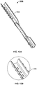
- FIG. 14A illustrates a keeper tray and filler deformation equality in low sanity fillers on application of site load according to an embodiment
- FIG. 14B illustrates a keeper tray and filler deformation equality in filler of present invention on application of site load according to an embodiment
- FIG. 15A - FIG. 15D illustrates a top view of the various shape and configuration of a continuous spacer embodied on the high-density fillers according to an embodiment
- FIG. 15E - FIG. 15H illustrates a side view of the various shape and configuration of a continuous spacer embodied on the high-density fillers according to an embodiment
- FIG. 15I - FIG. 15L illustrates a perspective view of the various shape and configuration of a continuous spacer embodied on the high-density fillers according to an embodiment
- FIG. 16A illustrates a top perspective view of the filler incorporated with an exhaust hole according to an embodiment
- FIG. 16B illustrates a top view of the filler incorporated with an exhaust hole according to an embodiment
- FIG. 16C illustrates a side sectional view of the filler incorporated with an exhaust hole according to an embodiment
- FIG. 17A illustrates a variable length of the installable legs or indicators attached on the bottom portion of the lower keeper tray according to an embodiment
- FIG. 17B shows the installable legs or indicators attached on the upper keeper tray according to an embodiment
- FIG. 18A illustrates a side view of the filler incorporated with the keeper tray, volumetric filling element, and installable legs or indicators attached on the bottom portion of the lower keeper tray according to an embodiment
- FIG. 18B illustrates a side view of the filler incorporated with external holder and spacer
- FIG. 18C illustrates a perspective view of the filler incorporated with the exhaust hole in the volumetric filling element, and external holder and spacer;
- FIG. 19A - FIG. 19P illustrate a perspective view of various shape and configuration of the volumetric filling element according to an embodiment
- FIG. 20A - FIG. 20Q illustrate first type, where the spacer is a part of the keeper tray, according to an embodiment
- FIG. 20R - FIG. 20X illustrate second type, where the keeper tray is installed with external spacers, according to an embodiment
- FIG. 21A - FIG. 21N illustrates a side perspective view of various shape and configuration of the external spacer according to an embodiment
- FIG. 21O and FIG. 21P illustrates a side perspective view of various shape and configuration of the external spacer with holes installable on the keeper tray according to an embodiment
- FIG. 22A - FIG. 22C illustrate a top perspective view of various shape and configuration of the rebar assembled on the volumetric filling element according to an embodiment
- FIG. 23A and FIG. 23B illustrate a top perspective view on various shape and configuration of the belt assembled on the upper keeper tray of the fillers according to an embodiment
- FIG. 24A and FIG. 24B illustrate a side view and side perspective view of the belt assembled on the holder according to an embodiment.
- FIG. 25A - FIG. 25G illustrate holes on the different shapes of the volumetric filling element according to an embodiment
- FIG. 26 illustrate a method for implementing fillers in a two-way concrete slab for building structures.
- the present invention generally relates to a slab filler, and more particularly relates to a slab filler and method for implementing fillers in a two-way concrete slab for building structures, bridge and foundation.
- Waffle Slabs with non-permanent fillers can be mentioned as former technical systems.
- design strips were orthogonal “T” shaped ribbed slabs which carries load in two directions.
- the bottom surface of these slabs become voided after pouring concrete due to removing formworks, that needs installation of false ceiling in addition to difficulties in operation.
- these kind of waffle slabs with invented permanent filler not only will have complete flat underside surface after removing of forms due to permanent filler in concrete but also due to conversion of ribbed slab section from “T” shaped to I shaped (because of concrete entry under the filler), have higher stiffness than old waffle slabs.
- a slab filler 100 for use in a two-way concrete slab for building structures is disclosed, referring to all the figures.
- the filler 100 comprises an upper keeper tray 102 and a lower keeper tray 104 , and a volumetric filling element 106 arranged in between the upper keeper tray 102 and the lower keeper tray 104 .
- FIG. 1A - FIG. 1R top view, side view and perspective view of the various shapes of volumetric filling element 106 in the filler 100 are illustrated.
- the volumetric filling element 106 in the filler 100 could be incorporated in different shapes such as cube, cylinder, sphere, truncated pyramid, or a combination thereof.
- the volumetric filling element 106 in the filler 100 is in predetermined dimension, thickness and shape.
- Predetermined dimension of the volumetric filling element 106 is done by optimizing the filler length and width based on the quantity and span of load applied on it.
- Predetermined thickness of the filler 100 is calculated and maintained to avoid slab deformation.
- FIG. 2A - FIG. 2F top view, side view and perspective view of the various configuration and shapes of keeper tray ( 102 or 104 ) are illustrated.
- Said keeper tray comprises several features and components to support the volumetric filling element 106 of the filler 100 .
- FIG. 2G and FIG. 2H top view and perspective view of the keeper tray ( 102 or 104 ) with a punch resistant plate 108 are illustrated.
- the upper keeper tray 102 is attached to a top of the volumetric filling element 106 and the lower keeper tray 104 is attached to a bottom of the volumetric filling element 106 .
- the volumetric filling element 106 is a high-density material, where the filler 100 for use in a two-way concrete slab is incorporated without upper keeper tray 102 and lower keeper tray 104 .
- the volumetric filling element 106 is made of a light-weight material.
- the volumetric filling element 106 is carved to enable adjustable geometrical structure and size of the filler 100 .
- the light-weight material is selected from a group comprising any one of polystyrene, polyurethane, polyethylene, concrete foam clay, gas concrete, autoclaved aerated concrete (AAC), or any combination thereof.
- the light-weight material is a sound insulator, heat insulator, or both.
- the volumetric filling element 106 is a cubic-shaped element with one or more chamfer edges.
- the cubic-shaped element with one or more chamfer edges is configured to prevent concrete honeycombing at the bottom surface of the slabs.
- the cubic-shaped element with one or more chamfer edges further enables haunch connection in a junction between a web and a flange.
- the haunch connection is configured to increase section modulus of one or more joists formed between the volumetric filling elements 106 .
- the joist comprises one or more stirrups and steel wires. The stirrups and steel wires fastens the upper keeper tray 102 and the lower keeper tray 104 to encompass the volumetric filling element 106 to resist buoyancy force of the feeding concrete.
- the haunch connection is further configured to reduce stress concentration in the junction between web and flange.
- concrete flow buoyancy force during voided slabs concrete pouring is 190 Kg/m 2 , for example, assuming each void volume is equal to 0.052 m 3 . While the most weight of upper keeper tray and lower keeper tray, workers and equipment rarely exceed from 120 Kg/m 2 .
- a method to control buoyancy force is utilization of concrete weight that earn up to 540 Kg/m 2 , by fastening top mesh to bottom mesh. Rebars on upper keeper tray and rebars under lower keeper tray is closed to each other by stirrups, and to fasten lower keeper tray by steel wire in appropriate distances. Henceforth, the concrete weight force confronts with the concrete flow uplift force.
- the filler 100 for use in a two-way concrete slab further comprises one or more spacers 206 positioned on the keeper tray ( 102 or 104 ).
- the upper keeper tray 102 and the lower keeper tray 104 are fasten or welded via one or more stirrups to the rebar 204 .
- the rebar 204 is configured to form coop or hutch around the volumetric filling element 106 .
- the rebar 204 is further configured to maintain predetermined distance between the volumetric filling elements 106 to resist shear force and moments in the slab.
- the upper keeper tray 102 and lower keeper tray 104 is made of plastic, wood or steel.
- the volumetric filling element 106 is one of geometric shape including cube, cylinder, sphere, truncated pyramid and combination thereof.
- the keeper tray ( 102 or 104 ) is configured to distribute load on the volumetric filling element 106 by the punch resistant plate 108 .
- the keeper tray ( 102 or 104 ) comprises one or more ridges 302 . Referring to FIG. 3A and FIG. 3B , top and sectional view of the keeper tray ( 102 or 104 ) implemented with ridges or linear ridges 302 such as triple linear ridges is illustrated.
- the keeper tray ( 102 or 104 ) is further configured to securely hold the volumetric filling element 106 .
- the filler 100 for use in a two-way concrete slab further comprises one or more spacers 206 positioned on the keeper tray ( 102 or 104 ).
- the spacers 206 is positioned around the keeper tray ( 102 or 104 ) to maintain sufficient distance/space between the rebar 204 and filler 100 .
- the spacer 206 is configured to provide sufficient resistance under point load and tensile forces. For example, the point load that created by walking of a workman, and tensile force under the influence of bending of loads in the volumetric filling elements 106 .
- the filler 100 further comprises one or more grooves 304 (shown in FIG. 6A - FIG. 6D ) at an end of the spacer 206 , configured to securely hold one or more belts 308 .
- the filler 100 further comprises at least one belt 308 configured to attach at least one upper keeper tray 102 , lower keeper tray 104 , or both.
- the belt 308 is configured to connect the filler 100 to an adjacent filler of the concrete slab, and support at least partial load exerted by the rebar 204 of the concrete slab.
- the belt 308 is configured perform two important tasks. First, to fix the fillers 100 in all directions with a calculated or predetermined space from each other and prevent the movement of the volumetric filling elements 106 . After pouring/feeding concrete, the space between the volumetric filling elements 106 forms a concrete joist in the slab. In the other word, the joist width is the space, which is created by belts 308 . Second, the belts 308 is configured to hold top rebar 204 located between the two volumetric filling elements 106 . Top rebar 204 in the filler 100 is the concrete joists top reinforcement.
- the belt 308 is configured to securely hold the fillers 100 , via a fastening means.
- the incorporation of the belt 308 on the keeper tray ( 102 or 104 ) depends on shape and location of the keeper tray ( 102 or 104 ) and belt 308 , and number of ridges and grooves in the keeper tray ( 102 or 104 ) and belt 308 .
- the belt 308 is configured to limit one or more movement of at least two volumetric filling elements 106 .
- FIG. 6A - FIG. 6D different view of the keeper tray ( 102 or 104 ) incorporated with grooves 304 on the belt 308 are illustrated.
- the grooves 304 on the keeper tray ( 102 or 104 ) is configured to lock the belt 308 firmly via one or more ridges 302 .
- the belt 308 and the groove 304 locking assembly will prevent the belt 308 jumping out of the keeper tray ( 102 or 104 ).
- the linear ridges 302 on the keeper tray ( 102 or 104 ) and grooves 304 on the belt 308 to limit one or movement of at least two volumetric filling elements 106 .
- the movement is horizontal, vertical or rotational movement.
- the belt 308 is further configured to position the rebar 204 between the volumetric filling elements 106 .
- the filler 100 further comprises a plurality of indicators 202 positioned in all, or some corners of the keeper tray ( 102 or 104 ) supported via one or more buttress 208 .
- the buttress 208 is configured to resist bending of the indicators 202 .
- FIG. 8 and FIG. 9 different views of the connected fillers 100 incorporated with the legs or indicators 202 are illustrated.
- the indicator 202 is configured to indicate an amount or level of a concrete fed on the filler 100 .
- the indicator 202 is configured to indicate thickness of the concrete fed on the voided volumetric filling element 106 .
- Installable legs 202 with variable length is configured to change the lower slab thickness in various condition.
- variable length of the installable legs attached on the bottom portion of the lower keeper tray 104 in the connected fillers ( 100 and 100 ′) is illustrated.
- the indicator 202 is a plurality of installable legs with pre-determined length mounted below the lower keeper tray 104 to allow concrete to reach under the lower keeper tray 104 while feeding the concrete.
- the plurality of installable legs is variable in length.
- the installable legs or indicators 109 attached on the upper keeper tray 102 in the connected fillers ( 100 and 100 ′) is illustrated.
- the indicator 109 is positioned on the upper keeper tray 102 to indicate the status of concrete thickness fed on the voided volumetric filling element 106 .
- the at least one keeper tray ( 102 or 104 ) further comprises one or more nail-shaped appendices 105 .
- the nail-shaped appendices 105 are configured to attach at least one keeper tray ( 102 or 104 ) to the volumetric filling element 106 , via an adhesive.
- the spacer 206 and belt 308 in the keeper tray ( 102 or 104 ) is configured to receive one or more rebar 204 . Referring to FIG. 11A - FIG.
- the belt 308 comprises one or more linear grooves 310 .
- the linear grooves 310 in the belt 308 is configured to prevent rotation of the volumetric filling element 106 under the influence of the site load movement.
- the belt 308 further comprises one or more additional ridges 306 on a wall of the belt 308 to lock the grooves 304 in the spacer 206 .
- FIG. 13 an arrangement of fillers 100 connected via the belts 308 and the rebar 204 is illustrated.
- the belt 308 is configured to connect one or more volumetric filling elements 106 .
- volumetric filling element 106 deformation equality in low density fillers on application of site load is illustrated.
- keeper tray ( 102 or 104 ) and volumetric filling element 106 deformation equality in filler of present invention on application of site load is illustrated.
- Use of low density fillers without matched keeper trays increase risk of fractures in fillers under the influence of site loads, for example, on moving construction workman or equipment.
- FIG. 15A - FIG. 15L top view, side view and perspective view of the various shape and configuration of a continuous spacer 206 ′ embodied on the high-density fillers 100 are illustrated.
- the spacer 206 ′ is a continuous fabric spacer.
- the volumetric filling element 106 is a high-density material with embodied spacer 206 ′, where the filler 100 for use in a two-way concrete slab is incorporated without upper keeper tray 102 and lower keeper tray 104 .
- the spacer 206 ′ embodied on the high-density filler 100 performs similar to the keeper tray ( 102 or 104 ) to provide sufficient space between the rebar 204 and filler 100 and perform as a stand under the filler 100 to seat on the rebar 204 .
- the volumetric filling element 106 further includes one or more exhaust holes 110 to allow exit of the trapped air.
- the exhaust holes 110 embedded in the center of filler 100 .
- the exhaust holes 110 could be of various sizes, but it is necessary to have enough diameter for vibrator ingression.
- One of the most important benefits of the volumetric filling element 106 is the ability of size optimizing proportional to loads and span. In other words, the optimized size of elements depends on amount and effective span of an applied load.
- the volumetric filling element 106 is variable size from 65 ⁇ 65 cm to 45 ⁇ 45 cm.
- the exhaust holes 110 passing through the element 106 from a bottom to a top of the volumetric filling element 106 is utilized in large size elements such as 60 ⁇ 60 cm, to exit the bottom surface trapped air and bring the vibrator to the center of the lower concrete slab. Further, the exhaust hole 110 in large volumetric filling element 106 prevents honeycombing in the lower concrete slab.
- the present invention comprises any one of the two types of keeper tray ( 102 or 104 ).
- first type of keeper tray ( 102 or 104 ) the spacer 206 is a part of the keeper tray. This configuration is single-piece configuration, with the spacer 206 on top.
- the second type of keeper tray ( 102 or 104 ) uses external spacers 206 that are positioned on the keeper trays ( 102 or 104 ).
- the keeper tray ( 102 or 104 ) does not require additional spacer, or other external spacers 206 . Further, the spacer 206 is detachably fixed to the keeper tray ( 102 or 104 ) in different configuration.
- FIG. 20A - FIG. 20Q a first type is illustrated, where the spacer is a part of the keeper tray ( 102 or 104 ) which does not require external spacers.
- FIG. 20R - FIG. 20X a second type is illustrated, where the keeper tray ( 102 or 104 ) are installed with external spacer 206 (shown in FIG. 21A - FIG. 21N ).
- FIG. 21N illustrates a side perspective view of various shape and configuration of the external spacer 206 according to an embodiment.
- FIG. 21O and FIG. 21P illustrates a side perspective view of various shape and configuration of the external spacer 206 installable on the keeper tray ( 102 or 104 ) according to an embodiment.
- the external spacers 206 comprises one or more holes, as shown in FIG. 21O and FIG. 21P .
- FIG. 18A side view of the filler 100 incorporated with the volumetric filling element 106 , steel, plastic, wooden or polymeric surrounding holder 107 attached on the bottom portion of the volumetric filling elements 106 is illustrated.
- FIG. 18B side view of the filler 100 incorporated without the keeper tray ( 102 or 104 ) is illustrated.
- FIG. 18C perspective view of the filler 100 incorporated with an exhaust hole 110 in the volumetric filling element 106 , and external spacers 206 attached on the top portion of the volumetric filling element 106 , is illustrated.
- the volumetric filling element 106 is a high-density material with embodied spacer shaped configuration, where the filler 100 for use in a two-way concrete slab is incorporated without upper keeper tray 102 and lower keeper tray 104 .
- the spacer shaped configuration embodied on the high-density filler 100 performs similar to the keeper tray ( 102 or 104 ) to provide sufficient space between the rebar 204 and filler 100 and perform as a stand or keeper tray under the filler 100 to seat on the rebar 204 .
- top perspective view of various shape and configuration of the rebar 204 assembled on the fillers 100 are illustrated.
- the rebar 204 is configured to assemble based on different configuration of the holder 107 .
- FIG. 23A and FIG. 23B top perspective view on various shape and configuration of the belt 308 assembled on the upper keeper tray 102 of one filler 100 to the adjacent filler 100 ′ are illustrated.
- FIG. 24A and FIG. 24B side view and side perspective view of the belt 308 assembled on the holder 107 of one filler 100 to the adjacent filler 100 ′ with exhaust hole 110 are illustrated.
- the belt 308 is made of different shape and configuration.
- the volumetric filling element 106 further includes one or more exhaust holes 110 .
- the exhaust holes 110 embedded in the center of filler 100 .
- the exhaust holes 110 could be of various sizes, but it is necessary to have enough diameter for vibrator ingression.
- One key benefit of the volumetric filling element 106 is the ability of size optimization proportional to loads and span. In other words, the optimized size of elements depends on amount and effective span of an applied load.
- the volumetric filling element 106 is variable size from 65 ⁇ 65 cm to 45 ⁇ 45 cm.
- the exhaust holes 110 passing through the element 106 from a bottom to a top of the volumetric filling element 106 is utilized in large size elements such as 60 ⁇ 60 cm, to exit the bottom surface trapped air and bring the vibrator to the center of the lower concrete slab. Further, the exhaust hole 110 in large volumetric filling element 106 prevents honeycombing in the lower concrete slab.
- a method 500 for implementing fillers 100 (as described in above paragraphs and figures) in a two-way concrete slab for building structures is disclosed, according to an embodiment.
- the method 500 comprises providing an upper keeper tray and a lower keeper tray with one or more spacers, or some external spacers positioned on the keeper tray.
- the method 500 comprises providing a plurality of indicators positioned in all corners or at least one corner of the keeper tray supported via one or more buttress to indicate an amount or level of a concrete fed on the filler.
- the method 500 further includes providing one or more grooves at an end or at some side of the spacers or trays, configured to securely hold one or more belts.
- the spacer and belt in the keeper tray is configured to receive one or more rebar, said at least one belt is configured to attach at least one upper keeper tray, lower keeper tray, or both.
- the method 500 further includes arranging a volumetric filling element in between the upper keeper tray and the lower keeper tray or in the rebar assembled or between external spacers and holder.
- the method 500 comprises attaching the upper keeper tray to a top of the volumetric filling element and the lower keeper tray to a bottom of the volumetric filling element, thereby forming a filler in a two-way concrete slab for building structures like that for assembled rebars and external spacers and holder.
- the method 500 includes implementation of different configuration and designs of filler with holder, external spacer, high density fillers or caged filler.
- the method 500 is also implemented with the spacer, which is a continuous fabric spacer.
- the volumetric filling element is a high-density material with embodied spacer, where the filler for use in a two-way concrete slab is incorporated without upper keeper tray and lower keeper tray.
- the spacer embodied on the high-density filler performs similar to the keeper tray to provide sufficient space between the rebar and filler and perform as a stand under the filler to seat on the rebar.
- the filler for use in a two-way concrete slab for building structures.
- the filler comprises an upper keeper tray and a lower keeper tray with one or more spacers positioned on said keeper tray; and a plurality of indicators positioned in all corners or at least one corner or in center of the keeper tray supported via one or more buttress to indicate an amount or level of a concrete fed on the filler.
- the filler may further comprise one or more grooves at an end of the spacer, configured to securely hold one or more belts, wherein the spacer and belt in the keeper tray is configured to receive one or more rebar, said at least one belt is configured to attach at least one upper keeper tray, lower keeper tray, or both.
- the filler further may comprise a volumetric filling element arranged in between the upper keeper tray and the lower keeper tray, wherein the upper keeper tray is attached to a top of the volumetric filling element and the lower keeper tray is attached to a bottom of the volumetric filling element.
- the volumetric filling element may be of a high-density material, such that the said volumetric filling material may be incorporated without upper keeper tray and lower keeper tray.
- the volumetric filling element may be made of a light-weight material, and the volumetric filling element is carved to enable adjustable geometrical structure and size of the filler.
- the light-weight material may be made from polystyrene, polyurethane, polyethylene, concrete foam clay, gas concrete, autoclaved aerated concrete (AAC), or any combination thereof.
- the light-weight material may be a sound insulator, heat insulator, or both.
- the volumetric filling element may be a cubic-shaped element with one or more chamfer edges.
- the cubic-shaped element with one or more chamfer edges enables haunch connection in a junction between a web and a flange.
- This haunch connection may be configured to increase section modulus of one or more joists formed between the volumetric filling elements.
- the haunch connection may further be configured to reduce stress concentration in the junction between the web and flange.
- the joist may comprise one or more stirrups and steel wires, with the stirrups and steel wires fastening to the upper keeper tray and the lower keeper tray to encompass the volumetric filling element to resist buoyancy force of the feeding concrete.
- the upper keeper tray and the lower keeper tray are fastened or welded via one or more stirrups to a rebar.
- the rebar may be configured to form coop or hutch around the volumetric filling element, and/or to resist shear force and movements on the concrete slab.
- the upper keeper tray and lower keeper tray may be made of plastic, wood or steel.
- the volumetric filling element may be one of geometric shape including cube, cylinder, sphere, truncated pyramid and combination thereof.
- the keeper tray may be configured to distribute load on the volumetric filling element.
- the keeper tray may be further configured to securely hold the volumetric filling element.
- the keeper tray in one example, may comprise one or more ridges.
- the filler may further comprise one or more spacers positioned around the keeper tray.
- the filler may further comprise one or more grooves at an end of the spacer, configured to securely hold one or more belts.
- the belt may be configured to connect a filler to an adjacent filler of the concrete slab, and support at least partial load exerted by the rebar of the concrete slab.
- the belt may be configured to securely hold both upper keeper tray and lower keeper tray of all the volumetric filling elements via a fastening means.
- the belt may be incorporated on the keeper tray depends on shape and location of the keeper tray and belt, and number of ridges and grooves in the keeper tray and belt.
- the belt may be configured to limit one or more movement of at least two volumetric filling elements. In an example, the belt may be further configured to position the rebar between the volumetric filling elements.
- the indicator may be configured to indicate thickness of the concrete fed on the voided volumetric filling element.
- the indicator may be positioned on the upper keeper tray to indicate the status of concrete thickness fed on the voided volumetric filling element.
- the installable legs with pre-determined length mounted on the lower keeper tray to allow concrete to reach under the lower keeper tray while feeding the concrete.
- the at least one keeper tray further may comprise one or more nail-shaped appendices. These nail-shaped appendices may be configured to attach at least one keeper tray to the volumetric filling element via an adhesive.
- the belt may comprise one or more linear grooves, and/or one or more additional ridges on a wall of the belt to lock the grooves in the keeper tray.
- the belt may be configured to connect one or more fillers.
- the spacer may be a continuous fabric spacer.
- the volumetric filling element may further include one or more exhaust holes to allow exit of the trapped air.
- the filler for use in a two-way concrete slab for building structures, bridges and foundation.
- the filler comprises an upper keeper tray and a lower keeper tray; and a volumetric filling element arranged in between the upper keeper tray and the lower keeper tray, wherein the upper keeper tray is attached to a top of the volumetric filling element and the lower keeper tray is attached to a bottom of the volumetric filling element.
- the volumetric filling element may be made of a light-weight material, and be carved to enable adjustable geometrical structure and size of the filler.
- the filler may comprise a plurality of volumetric filling element, wherein the volumetric filling element is a high-density material and embodied with a continuous fabric spacer, and such that the volumetric filling element is incorporated without the upper keeper tray and the lower keeper tray.
- the method 500 comprises providing an upper keeper tray and a lower keeper tray with one or more spacers positioned on the keeper tray; and providing a plurality of indicators positioned in all corners or at least one corner of the keeper tray supported via one or more buttress to indicate an amount or level of a concrete fed on the filler.
- the method 500 further may comprise providing one or more grooves at an end of the spacer, configured to securely hold one or more belts, wherein the spacer and belt in the keeper tray is configured to receive one or more rebar, said at least one belt is configured to attach at least one upper keeper tray, lower keeper tray, or both.
- the method 500 may further comprise arranging a volumetric filling element in between the upper keeper tray and the lower keeper tray, and attaching the upper keeper tray to a top of the volumetric filling element and the lower keeper tray to a bottom of the volumetric filling element, thereby forming a filler in a two-way concrete slab for building structures.
- the volumetric filling element is a high-density material, wherein the said volumetric filling material is incorporated without upper keeper tray and lower keeper tray.
- the light-weight material may be selected from a group comprising any one of polystyrene, polyurethane, polyethylene, concrete foam clay, gas concrete, autoclaved aerated concrete (AAC), or any combination thereof.
- the cubic-shaped element with one or more chamfer edges enables haunch connection in a junction between a web and a flange.
- the haunch connection may be configured to increase section modulus of one or more joists formed between the volumetric filling elements.
- the haunch connection may further be configured to reduce stress concentration in the junction between web and flange.
- the joist may comprise one or more stirrups and steel wires, wherein said stirrups and steel wires fastens the upper keeper tray and the lower keeper tray to encompass the volumetric filling element to resist buoyancy force of the feeding concrete.
- the incorporation of the belt on the keeper tray may depend on shape and location of the keeper tray and belt, and number of ridges and grooves in the keeper tray and belt, and the belt may be configured to limit one or more movement of at least two volumetric filling elements, and further wherein the belt is further configured to position the rebar between the volumetric filling elements.
- the indicator may be configured to indicate the thickness of the concrete fed on the voided volumetric filling element, and the indicator may be positioned on the upper keeper tray to indicate the status of concrete thickness fed on the voided volumetric filling element.
- At least one of upper keeper tray and lower keeper tray comprises an external plate spacer configured to attach the filler and reinforce the filler against fracture, punching, tumbling and rupture.
- the filler is attached to the external plate spacer by a compatible glue and nail shaped appendixes.
- the filler can be attached to the external plate spacer by a compatible glue and/or nail shaped appendixes.
- the filler is attached to the external plate spacer using a combination of DM5 glue with water and wallpaper adhesive powder.
- the filler may be attached to the external plate spacer using a combination of DM5 glue with water and wallpaper adhesive powder at a ratio of 48% Water, 47% DM5 and 5% wallpaper adhesive powder. This exact ratio of these three components was surprisingly found to provide superior functional qualities with the advantage of it being more economical and practical. Interestingly, the same three components mixed at different ratios provided less than optimal results.
- the glue and component combinations that were tested include wood glue, wood glue and water, DM5 glue, DM5 glue and water, wallpaper adhesive powder and water, combination of DM5 glue, water, and wallpaper adhesive powder, all-purpose adhesives that are solvent free and water based, two-component adhesives, and instant glues.
- the characteristics of different types/mixtures of glues are shown in Table 1. Based on the characteristics of the filler or external plate spacer, particular type/mixture of the glue is used.
- DM5 may be a strong glue with good water resistance, it was shown to be highly inferior if used by itself on plastic surfaces for example. The inventors were able to experiment and discover that mixing a certain amount of a certain powder into the DM5 can vastly improve, with water added, the overall function for this particular purpose.
- the method 500 further may include embedding one or more holes in the length of the surrounded spacer for concrete entry in order to prevent the creation of hollow spaces under surrounding spacer and to prevent the weakening of the top slab. These one or more holes may be configured to allow the entry of concrete under the spacers that are on the trays, such that any space or void that is under the spacer is filled with concrete and air pockets underneath the spacer are minimized, thereby improving strength and integrity.
- the method 500 further may comprise embedding one or more holes on the spacers, wherein said holes are configured to allow the entry of concrete through the holes to under the spacers that are on the trays, such that voids or air pockets under the spacers are generally filled with concrete, thereby improving strength and integrity.
- the fillers and external plate spacers can be protected and attached by packing with shrinking flexible nylon or stretch film. This has the benefit of protecting the fillers and external plate spacers from physical handling and overall damage, including for example scratches or divots being made or segments falling off. It can be an extra protective method, and it can be used with or without the glue in one example.
- the disclosure is directed to a filler for substituting a part of concrete in a two-way concrete slab when build a structure.
- the fillers comprising a top keeper tray and a underside keeper tray; and a volumetric filling element made of a light-weight material, wherein the volumetric filling element is arranged in between the top keeper tray and the underside keeper tray, and wherein the top keeper tray is attached to a top of the volumetric filling element and the underside keeper tray is attached to a bottom of the volumetric filling element.
- a cutting of the light-weight material of the volumetric filling element enables adjusting a geometry of the volumetric filling element and thereby enables adjusting a geometry of the filler.
- the volumetric filling element may be a cubic-shaped element with chamfer edges.
- the top keeper tray may comprise an indicator for indicating a thinness of a concrete poured on the filler.
- the at least one of the top keeper tray and the underside keeper tray may be made of plastic.
- the at least one of the top keeper tray and the underside keeper tray may comprise a plurality of nail-shape appendices for attaching to the at least one keeper tray to the filler.
- At least one of the top keeper tray and the underside keeper tray is glued to the filler.
- the at least one of the top keeper tray and the underside keeper tray is made of the light-weight material, and wherein the at least one of the keeper tray and the volumetric filling element forms a continuous fabric.
- the volumetric filling element may comprise one or more exhaust holes passing through the element from a bottom to a top the element for allowing an exit of trapped air from a top of the element during concrete pouring.
- the filler may comprise a plurality of legs mounted below the underside keeper tray for allowing concrete to reach under the underside keeper tray during concrete pouring.
- the filler may further comprise at least one connection belt attached to at one of the top keeper tray and the underside keeper tray, the connection belt being arranged and configured for connecting the filler to an adjacent filler of the concrete slab; and at least partially bearing a load exerted by a rebar of the concrete slab.
- the disclosure is directed to a method 500 of producing a filler for substituting a part of concrete in a two-way concrete slab when build a structure, comprising: providing an top keeper tray and a underside keeper tray; providing a volumetric filling element made of a light-weight material, arranging the volumetric filling element in between the top keeper tray and the underside keeper tray, and attaching the top keeper tray to a top of the volumetric filling element and the underside keeper tray to a bottom of the volumetric filling element.
Landscapes
- Engineering & Computer Science (AREA)
- Architecture (AREA)
- Civil Engineering (AREA)
- Structural Engineering (AREA)
- Physics & Mathematics (AREA)
- Electromagnetism (AREA)
- Reinforcement Elements For Buildings (AREA)
- Bridges Or Land Bridges (AREA)
Applications Claiming Priority (1)
| Application Number | Priority Date | Filing Date | Title |
|---|---|---|---|
| PCT/IB2016/053384 WO2017212317A1 (en) | 2016-06-09 | 2016-06-09 | A slab filler |
Publications (2)
| Publication Number | Publication Date |
|---|---|
| US20190085558A1 US20190085558A1 (en) | 2019-03-21 |
| US10753088B2 true US10753088B2 (en) | 2020-08-25 |
Family
ID=56178398
Family Applications (1)
| Application Number | Title | Priority Date | Filing Date |
|---|---|---|---|
| US15/573,478 Active 2036-06-17 US10753088B2 (en) | 2016-06-09 | 2016-06-09 | Slab fillers and methods for implementing fillers in two-way concrete slabs for building structures |
Country Status (4)
| Country | Link |
|---|---|
| US (1) | US10753088B2 (de) |
| EP (1) | EP3289148A1 (de) |
| CA (1) | CA2986125C (de) |
| WO (1) | WO2017212317A1 (de) |
Cited By (2)
| Publication number | Priority date | Publication date | Assignee | Title |
|---|---|---|---|---|
| US20220282480A1 (en) * | 2021-03-08 | 2022-09-08 | Plascon Plastics Corporation | Lattice of hollow bodies with reinforcement member supports |
| US11851880B2 (en) * | 2018-04-08 | 2023-12-26 | Aus Chairs Pty Ltd | Reinforcing spacer |
Families Citing this family (3)
| Publication number | Priority date | Publication date | Assignee | Title |
|---|---|---|---|---|
| LU101468B1 (de) * | 2019-11-05 | 2021-05-11 | Unidome Deutschland Gmbh | Betonformungseinlage und Verfahren zum Herstellen einer Betonformungseinlage sowie Verfahren zum Herstellen eines Betonbauteils |
| IT202100024500A1 (it) * | 2021-09-23 | 2023-03-23 | Poseidon Gt S R L | Cassero di alleggerimento per manufatti in cemento armato e struttura modulare di alleggerimento impiegante tali casseri |
| CN115198753B (zh) * | 2022-06-20 | 2023-07-04 | 上海工程技术大学 | 一种结构体及其制作模具和应用 |
Citations (29)
| Publication number | Priority date | Publication date | Assignee | Title |
|---|---|---|---|---|
| US3229437A (en) * | 1957-09-03 | 1966-01-18 | Adie George Mountford | Concrete structures |
| US3495367A (en) * | 1965-12-21 | 1970-02-17 | Hideya Kobayashi | Precast lightweight reinforced concrete plank |
| US3789094A (en) * | 1971-05-06 | 1974-01-29 | Monostruct Corp Ltd | Method of producing a molded foamed structural member having a honeycomb core adapted for venting |
| US3908323A (en) * | 1974-07-11 | 1975-09-30 | Robert K Stout | Void creating device to be embedded in a concrete structure |
| US3922413A (en) * | 1974-06-03 | 1975-11-25 | Richard G Reineman | Lightweight, high strength, reinforced concrete constructions |
| US4116415A (en) * | 1977-04-20 | 1978-09-26 | Ward Edward B | Liner for concrete forms |
| US4141946A (en) * | 1976-07-07 | 1979-02-27 | Rauenhorst Gerald A | Hollow-core concrete slabs and the method of making the same |
| US4164831A (en) * | 1977-09-21 | 1979-08-21 | Messick William E | Heat insulating and sound absorbing concrete wall panel |
| US4213281A (en) * | 1977-12-12 | 1980-07-22 | Zarzosa Castilla Agustin F | Construction of roofs, floors and beams |
| US4663909A (en) * | 1985-03-12 | 1987-05-12 | Bridgestone Corporation | Outer heat insulating structure on a building roof |
| US4803108A (en) * | 1987-05-01 | 1989-02-07 | Essex Specialty Products, Inc. | Honeycomb reinforcing sheet for the reinforcement of panels and method of reinforcing panels |
| US5421136A (en) * | 1992-10-01 | 1995-06-06 | Fiberslab Pty Limited | Foundation construction |
| US5624622A (en) * | 1993-05-04 | 1997-04-29 | Foster-Miller, Inc. | Method of forming a truss reinforced foam core sandwich structure |
| US5632834A (en) * | 1990-09-27 | 1997-05-27 | Dornier Gmbh | Process for producing sandwich structures from fiber-reinforced ceramics |
| US5966881A (en) * | 1997-02-25 | 1999-10-19 | Mitsui Home Co., Ltd. | Base plate for foundation and foundation of structure |
| US6298622B1 (en) * | 1996-10-15 | 2001-10-09 | Plastedil, S.A. | Self-supporting construction element of expanded plastics, in particular for manufacturing floor elements and walls of buildings in general |
| US6581352B1 (en) * | 2000-08-17 | 2003-06-24 | Kamran Amirsoleymani | Concrete composite structural system |
| US6789366B1 (en) * | 1999-07-12 | 2004-09-14 | Febra Antonio Francico | Lost mould element for manufacturing reinforced concrete flat slabs |
| US20050138877A1 (en) * | 2003-12-30 | 2005-06-30 | Kenji Inoue | Plane lattice hollow concrete slab and cross arm brace |
| US20050224690A1 (en) * | 2004-04-12 | 2005-10-13 | Hobbs George J | Water-permeable concrete pad and form |
| US7143564B2 (en) * | 2003-11-19 | 2006-12-05 | Sonoco Development, Inc. | Reinforced fiber panel and method of forming same |
| US7596918B2 (en) * | 2001-11-03 | 2009-10-06 | Hills Danny W | Building apparatus for forming a wall construction and method for forming a wall using the apparatus |
| US7784235B2 (en) * | 2004-05-11 | 2010-08-31 | Plastedil S.A. | Load bearing construction element, in particular for manufacturing building floors, and floor structure incorporating such element |
| US8028485B2 (en) * | 2007-12-28 | 2011-10-04 | Cobiax Technologies Ag | Module having displacement bodies for the production of concrete elements |
| US8657984B1 (en) * | 2010-07-26 | 2014-02-25 | The United States Of America As Represented By The Secretary Of The Air Force | Method for fabricating composite grid-stiffened structures with integrated fluid channels |
| US8943771B2 (en) * | 2010-06-28 | 2015-02-03 | Alberto Alarcon Garcia | Lightweight slab or similar structural element which can receive equipment that is accessible and that can extend through the slab |
| US8955278B1 (en) * | 2014-05-16 | 2015-02-17 | Hilton R. Mills | Subfloor drainage panel |
| US8966855B1 (en) * | 2012-06-25 | 2015-03-03 | Martin P. Miller | Foundation system for modular system smart buildings |
| US10286626B2 (en) * | 2015-07-09 | 2019-05-14 | Skydex Technologies, Inc. | Pressure distributing aligned arrays of cushioning void cells |
Family Cites Families (10)
| Publication number | Priority date | Publication date | Assignee | Title |
|---|---|---|---|---|
| DE10004640A1 (de) * | 2000-02-03 | 2001-08-09 | Haeussler Planung Gmbh | Hohlkörper mit Abstandhaltern |
| US20020092249A1 (en) | 2001-01-17 | 2002-07-18 | Runhorn Pretech Engineering Co., Ltd. | Partially prefabricated waffle slab |
| JP2005220571A (ja) * | 2004-02-04 | 2005-08-18 | Kurimoto Ltd | 二方向コンクリートボイドスラブ |
| JP2005282010A (ja) * | 2004-03-29 | 2005-10-13 | Kurimoto Ltd | コンクリートボイドスラブ |
| JP2009191542A (ja) * | 2008-02-15 | 2009-08-27 | Hayashi Bussan Hatsumei Kenkyusho:Kk | 中空スラブ |
| ES2308941B1 (es) * | 2008-02-29 | 2009-07-28 | Industrias Tomas Morcillo, S.L. | Suelo tecnico y procedimiento de instalacion. |
| JP5428437B2 (ja) * | 2009-03-25 | 2014-02-26 | 株式会社熊谷組 | 床スラブ及びその施工法 |
| KR100958407B1 (ko) * | 2009-08-18 | 2010-05-18 | 삼성중공업 주식회사 | 경량성형재조립체에 의한 중공슬래브의 시공구조 |
| AR073837A1 (es) * | 2009-10-29 | 2010-12-09 | Levinton Ricardo Horacio | Metodo constructivo para realizar estructuras livianas, como ser losas, prelosas, plateas, tabiques y vigas, con discos alivianadores y mallas disenadas especificamente para este metodo |
| CN202125011U (zh) * | 2010-12-14 | 2012-01-25 | 徐焱 | 一种控制填充材料位置的垫块 |
-
2016
- 2016-06-09 WO PCT/IB2016/053384 patent/WO2017212317A1/en active Application Filing
- 2016-06-09 EP EP16731334.5A patent/EP3289148A1/de not_active Withdrawn
- 2016-06-09 US US15/573,478 patent/US10753088B2/en active Active
-
2017
- 2017-11-20 CA CA2986125A patent/CA2986125C/en active Active
Patent Citations (29)
| Publication number | Priority date | Publication date | Assignee | Title |
|---|---|---|---|---|
| US3229437A (en) * | 1957-09-03 | 1966-01-18 | Adie George Mountford | Concrete structures |
| US3495367A (en) * | 1965-12-21 | 1970-02-17 | Hideya Kobayashi | Precast lightweight reinforced concrete plank |
| US3789094A (en) * | 1971-05-06 | 1974-01-29 | Monostruct Corp Ltd | Method of producing a molded foamed structural member having a honeycomb core adapted for venting |
| US3922413A (en) * | 1974-06-03 | 1975-11-25 | Richard G Reineman | Lightweight, high strength, reinforced concrete constructions |
| US3908323A (en) * | 1974-07-11 | 1975-09-30 | Robert K Stout | Void creating device to be embedded in a concrete structure |
| US4141946A (en) * | 1976-07-07 | 1979-02-27 | Rauenhorst Gerald A | Hollow-core concrete slabs and the method of making the same |
| US4116415A (en) * | 1977-04-20 | 1978-09-26 | Ward Edward B | Liner for concrete forms |
| US4164831A (en) * | 1977-09-21 | 1979-08-21 | Messick William E | Heat insulating and sound absorbing concrete wall panel |
| US4213281A (en) * | 1977-12-12 | 1980-07-22 | Zarzosa Castilla Agustin F | Construction of roofs, floors and beams |
| US4663909A (en) * | 1985-03-12 | 1987-05-12 | Bridgestone Corporation | Outer heat insulating structure on a building roof |
| US4803108A (en) * | 1987-05-01 | 1989-02-07 | Essex Specialty Products, Inc. | Honeycomb reinforcing sheet for the reinforcement of panels and method of reinforcing panels |
| US5632834A (en) * | 1990-09-27 | 1997-05-27 | Dornier Gmbh | Process for producing sandwich structures from fiber-reinforced ceramics |
| US5421136A (en) * | 1992-10-01 | 1995-06-06 | Fiberslab Pty Limited | Foundation construction |
| US5624622A (en) * | 1993-05-04 | 1997-04-29 | Foster-Miller, Inc. | Method of forming a truss reinforced foam core sandwich structure |
| US6298622B1 (en) * | 1996-10-15 | 2001-10-09 | Plastedil, S.A. | Self-supporting construction element of expanded plastics, in particular for manufacturing floor elements and walls of buildings in general |
| US5966881A (en) * | 1997-02-25 | 1999-10-19 | Mitsui Home Co., Ltd. | Base plate for foundation and foundation of structure |
| US6789366B1 (en) * | 1999-07-12 | 2004-09-14 | Febra Antonio Francico | Lost mould element for manufacturing reinforced concrete flat slabs |
| US6581352B1 (en) * | 2000-08-17 | 2003-06-24 | Kamran Amirsoleymani | Concrete composite structural system |
| US7596918B2 (en) * | 2001-11-03 | 2009-10-06 | Hills Danny W | Building apparatus for forming a wall construction and method for forming a wall using the apparatus |
| US7143564B2 (en) * | 2003-11-19 | 2006-12-05 | Sonoco Development, Inc. | Reinforced fiber panel and method of forming same |
| US20050138877A1 (en) * | 2003-12-30 | 2005-06-30 | Kenji Inoue | Plane lattice hollow concrete slab and cross arm brace |
| US20050224690A1 (en) * | 2004-04-12 | 2005-10-13 | Hobbs George J | Water-permeable concrete pad and form |
| US7784235B2 (en) * | 2004-05-11 | 2010-08-31 | Plastedil S.A. | Load bearing construction element, in particular for manufacturing building floors, and floor structure incorporating such element |
| US8028485B2 (en) * | 2007-12-28 | 2011-10-04 | Cobiax Technologies Ag | Module having displacement bodies for the production of concrete elements |
| US8943771B2 (en) * | 2010-06-28 | 2015-02-03 | Alberto Alarcon Garcia | Lightweight slab or similar structural element which can receive equipment that is accessible and that can extend through the slab |
| US8657984B1 (en) * | 2010-07-26 | 2014-02-25 | The United States Of America As Represented By The Secretary Of The Air Force | Method for fabricating composite grid-stiffened structures with integrated fluid channels |
| US8966855B1 (en) * | 2012-06-25 | 2015-03-03 | Martin P. Miller | Foundation system for modular system smart buildings |
| US8955278B1 (en) * | 2014-05-16 | 2015-02-17 | Hilton R. Mills | Subfloor drainage panel |
| US10286626B2 (en) * | 2015-07-09 | 2019-05-14 | Skydex Technologies, Inc. | Pressure distributing aligned arrays of cushioning void cells |
Cited By (3)
| Publication number | Priority date | Publication date | Assignee | Title |
|---|---|---|---|---|
| US11851880B2 (en) * | 2018-04-08 | 2023-12-26 | Aus Chairs Pty Ltd | Reinforcing spacer |
| US20220282480A1 (en) * | 2021-03-08 | 2022-09-08 | Plascon Plastics Corporation | Lattice of hollow bodies with reinforcement member supports |
| US11566423B2 (en) * | 2021-03-08 | 2023-01-31 | Plascon Plastics Corporation | Lattice of hollow bodies with reinforcement member supports |
Also Published As
| Publication number | Publication date |
|---|---|
| EP3289148A1 (de) | 2018-03-07 |
| US20190085558A1 (en) | 2019-03-21 |
| WO2017212317A1 (en) | 2017-12-14 |
| CA2986125A1 (en) | 2017-12-09 |
| CA2986125C (en) | 2020-05-05 |
Similar Documents
| Publication | Publication Date | Title |
|---|---|---|
| CA2986125C (en) | Slab fillers and methods for implementing fillers in two-way concrete slabs for building structures | |
| US5809725A (en) | Sectional nog structure for fastening a covering element to a foamed plastic slab and construction element incorporating said structure | |
| US20060272251A1 (en) | Composite floor system with fully-embedded studs | |
| US8707644B2 (en) | Concrete flooring system formwork assembly having triangular support structure | |
| KR101860299B1 (ko) | 분리형 데크플레이트 시공방법 | |
| US3597890A (en) | Construction assembly | |
| JP5406563B2 (ja) | 合成梁、建築物、及び合成梁の施工方法 | |
| JPH10231578A (ja) | 建屋構造 | |
| US20120240497A1 (en) | Construction system | |
| US20020078646A1 (en) | Suspended concrete flooring system and method | |
| CA2678452C (en) | Device for anchoring concrete to an insulating panel and form employing the device | |
| US7937901B2 (en) | Tendon-identifying, post tensioned concrete flat plate slab and method and apparatus for constructing same | |
| JP6422795B2 (ja) | 複合梁及びこれを構成するPCa複合梁部材並びに複合ラーメン構造 | |
| US20070039276A1 (en) | Concrete reinforcer and method | |
| US20210317659A1 (en) | Slab fillers and methods for implementing fillers in two-way concrete slabs for building structures | |
| JP2006342645A (ja) | コンクリート構造体の施工方法と施工技術及び金具 | |
| KR102320411B1 (ko) | 망상형 전단보강대를 이용한 무량판 구조물의 슬래브-기둥 접합부 전단 보강구조 | |
| KR101875846B1 (ko) | 내부이음쇠로 제작된 펀칭전단보강재 및 이를 이용한 펀칭전단보강공법 | |
| ES2912902T3 (es) | Elemento de construcción prefabricado y sistema de construcción prefabricado | |
| JP6514458B2 (ja) | 補強構造物 | |
| US3570206A (en) | Monolithic concrete slab construction | |
| JPH09221706A (ja) | 路面用床版およびその敷設工法 | |
| US20030029112A1 (en) | Beam receptacle and method | |
| JPH03107047A (ja) | スラブ構築工法 | |
| JP5190651B2 (ja) | 壁の補強構造 |
Legal Events
| Date | Code | Title | Description |
|---|---|---|---|
| FEPP | Fee payment procedure |
Free format text: ENTITY STATUS SET TO UNDISCOUNTED (ORIGINAL EVENT CODE: BIG.); ENTITY STATUS OF PATENT OWNER: SMALL ENTITY |
|
| FEPP | Fee payment procedure |
Free format text: ENTITY STATUS SET TO SMALL (ORIGINAL EVENT CODE: SMAL); ENTITY STATUS OF PATENT OWNER: SMALL ENTITY |
|
| STPP | Information on status: patent application and granting procedure in general |
Free format text: DOCKETED NEW CASE - READY FOR EXAMINATION |
|
| STPP | Information on status: patent application and granting procedure in general |
Free format text: NON FINAL ACTION MAILED |
|
| STPP | Information on status: patent application and granting procedure in general |
Free format text: RESPONSE TO NON-FINAL OFFICE ACTION ENTERED AND FORWARDED TO EXAMINER |
|
| STPP | Information on status: patent application and granting procedure in general |
Free format text: NON FINAL ACTION MAILED |
|
| STPP | Information on status: patent application and granting procedure in general |
Free format text: NOTICE OF ALLOWANCE MAILED -- APPLICATION RECEIVED IN OFFICE OF PUBLICATIONS |
|
| STPP | Information on status: patent application and granting procedure in general |
Free format text: PUBLICATIONS -- ISSUE FEE PAYMENT VERIFIED |
|
| STCF | Information on status: patent grant |
Free format text: PATENTED CASE |
|
| MAFP | Maintenance fee payment |
Free format text: PAYMENT OF MAINTENANCE FEE, 4TH YR, SMALL ENTITY (ORIGINAL EVENT CODE: M2551); ENTITY STATUS OF PATENT OWNER: SMALL ENTITY Year of fee payment: 4 |