US10697450B2 - Pump having a top portion fixed to an external structure - Google Patents
Pump having a top portion fixed to an external structure Download PDFInfo
- Publication number
- US10697450B2 US10697450B2 US15/800,683 US201715800683A US10697450B2 US 10697450 B2 US10697450 B2 US 10697450B2 US 201715800683 A US201715800683 A US 201715800683A US 10697450 B2 US10697450 B2 US 10697450B2
- Authority
- US
- United States
- Prior art keywords
- pump
- external structure
- projection
- pump according
- vibration
- Prior art date
- Legal status (The legal status is an assumption and is not a legal conclusion. Google has not performed a legal analysis and makes no representation as to the accuracy of the status listed.)
- Active
Links
- 239000012530 fluid Substances 0.000 claims abstract description 107
- 230000002093 peripheral effect Effects 0.000 claims description 2
- 230000002787 reinforcement Effects 0.000 description 8
- 229910010293 ceramic material Inorganic materials 0.000 description 4
- 238000007789 sealing Methods 0.000 description 4
- 239000007788 liquid Substances 0.000 description 3
- 239000000463 material Substances 0.000 description 3
- 230000005540 biological transmission Effects 0.000 description 2
- 238000007599 discharging Methods 0.000 description 2
- 239000000853 adhesive Substances 0.000 description 1
- 230000001070 adhesive effect Effects 0.000 description 1
- 239000003513 alkali Substances 0.000 description 1
- 238000013459 approach Methods 0.000 description 1
- 238000005452 bending Methods 0.000 description 1
- 230000007423 decrease Effects 0.000 description 1
- 230000000694 effects Effects 0.000 description 1
- 230000005684 electric field Effects 0.000 description 1
- 229910052751 metal Inorganic materials 0.000 description 1
- 239000002184 metal Substances 0.000 description 1
- BITYAPCSNKJESK-UHFFFAOYSA-N potassiosodium Chemical compound [Na].[K] BITYAPCSNKJESK-UHFFFAOYSA-N 0.000 description 1
- 230000000750 progressive effect Effects 0.000 description 1
- 238000005086 pumping Methods 0.000 description 1
- 229910001220 stainless steel Inorganic materials 0.000 description 1
- 239000010935 stainless steel Substances 0.000 description 1
Images


Classifications
-
- F—MECHANICAL ENGINEERING; LIGHTING; HEATING; WEAPONS; BLASTING
- F04—POSITIVE - DISPLACEMENT MACHINES FOR LIQUIDS; PUMPS FOR LIQUIDS OR ELASTIC FLUIDS
- F04B—POSITIVE-DISPLACEMENT MACHINES FOR LIQUIDS; PUMPS
- F04B43/00—Machines, pumps, or pumping installations having flexible working members
- F04B43/02—Machines, pumps, or pumping installations having flexible working members having plate-like flexible members, e.g. diaphragms
- F04B43/04—Pumps having electric drive
- F04B43/043—Micropumps
- F04B43/046—Micropumps with piezoelectric drive
-
- F—MECHANICAL ENGINEERING; LIGHTING; HEATING; WEAPONS; BLASTING
- F04—POSITIVE - DISPLACEMENT MACHINES FOR LIQUIDS; PUMPS FOR LIQUIDS OR ELASTIC FLUIDS
- F04B—POSITIVE-DISPLACEMENT MACHINES FOR LIQUIDS; PUMPS
- F04B17/00—Pumps characterised by combination with, or adaptation to, specific driving engines or motors
- F04B17/003—Pumps characterised by combination with, or adaptation to, specific driving engines or motors driven by piezoelectric means
-
- F—MECHANICAL ENGINEERING; LIGHTING; HEATING; WEAPONS; BLASTING
- F04—POSITIVE - DISPLACEMENT MACHINES FOR LIQUIDS; PUMPS FOR LIQUIDS OR ELASTIC FLUIDS
- F04B—POSITIVE-DISPLACEMENT MACHINES FOR LIQUIDS; PUMPS
- F04B19/00—Machines or pumps having pertinent characteristics not provided for in, or of interest apart from, groups F04B1/00 - F04B17/00
- F04B19/20—Other positive-displacement pumps
- F04B19/22—Other positive-displacement pumps of reciprocating-piston type
-
- F—MECHANICAL ENGINEERING; LIGHTING; HEATING; WEAPONS; BLASTING
- F04—POSITIVE - DISPLACEMENT MACHINES FOR LIQUIDS; PUMPS FOR LIQUIDS OR ELASTIC FLUIDS
- F04B—POSITIVE-DISPLACEMENT MACHINES FOR LIQUIDS; PUMPS
- F04B35/00—Piston pumps specially adapted for elastic fluids and characterised by the driving means to their working members, or by combination with, or adaptation to, specific driving engines or motors, not otherwise provided for
- F04B35/04—Piston pumps specially adapted for elastic fluids and characterised by the driving means to their working members, or by combination with, or adaptation to, specific driving engines or motors, not otherwise provided for the means being electric
- F04B35/045—Piston pumps specially adapted for elastic fluids and characterised by the driving means to their working members, or by combination with, or adaptation to, specific driving engines or motors, not otherwise provided for the means being electric using solenoids
-
- F—MECHANICAL ENGINEERING; LIGHTING; HEATING; WEAPONS; BLASTING
- F04—POSITIVE - DISPLACEMENT MACHINES FOR LIQUIDS; PUMPS FOR LIQUIDS OR ELASTIC FLUIDS
- F04B—POSITIVE-DISPLACEMENT MACHINES FOR LIQUIDS; PUMPS
- F04B39/00—Component parts, details, or accessories, of pumps or pumping systems specially adapted for elastic fluids, not otherwise provided for in, or of interest apart from, groups F04B25/00 - F04B37/00
- F04B39/12—Casings; Cylinders; Cylinder heads; Fluid connections
- F04B39/121—Casings
-
- F—MECHANICAL ENGINEERING; LIGHTING; HEATING; WEAPONS; BLASTING
- F04—POSITIVE - DISPLACEMENT MACHINES FOR LIQUIDS; PUMPS FOR LIQUIDS OR ELASTIC FLUIDS
- F04B—POSITIVE-DISPLACEMENT MACHINES FOR LIQUIDS; PUMPS
- F04B43/00—Machines, pumps, or pumping installations having flexible working members
- F04B43/0009—Special features
-
- F—MECHANICAL ENGINEERING; LIGHTING; HEATING; WEAPONS; BLASTING
- F04—POSITIVE - DISPLACEMENT MACHINES FOR LIQUIDS; PUMPS FOR LIQUIDS OR ELASTIC FLUIDS
- F04B—POSITIVE-DISPLACEMENT MACHINES FOR LIQUIDS; PUMPS
- F04B43/00—Machines, pumps, or pumping installations having flexible working members
- F04B43/02—Machines, pumps, or pumping installations having flexible working members having plate-like flexible members, e.g. diaphragms
-
- F—MECHANICAL ENGINEERING; LIGHTING; HEATING; WEAPONS; BLASTING
- F04—POSITIVE - DISPLACEMENT MACHINES FOR LIQUIDS; PUMPS FOR LIQUIDS OR ELASTIC FLUIDS
- F04B—POSITIVE-DISPLACEMENT MACHINES FOR LIQUIDS; PUMPS
- F04B45/00—Pumps or pumping installations having flexible working members and specially adapted for elastic fluids
- F04B45/04—Pumps or pumping installations having flexible working members and specially adapted for elastic fluids having plate-like flexible members, e.g. diaphragms
- F04B45/047—Pumps having electric drive
-
- F—MECHANICAL ENGINEERING; LIGHTING; HEATING; WEAPONS; BLASTING
- F04—POSITIVE - DISPLACEMENT MACHINES FOR LIQUIDS; PUMPS FOR LIQUIDS OR ELASTIC FLUIDS
- F04B—POSITIVE-DISPLACEMENT MACHINES FOR LIQUIDS; PUMPS
- F04B53/00—Component parts, details or accessories not provided for in, or of interest apart from, groups F04B1/00 - F04B23/00 or F04B39/00 - F04B47/00
- F04B53/10—Valves; Arrangement of valves
- F04B53/102—Disc valves
-
- F—MECHANICAL ENGINEERING; LIGHTING; HEATING; WEAPONS; BLASTING
- F04—POSITIVE - DISPLACEMENT MACHINES FOR LIQUIDS; PUMPS FOR LIQUIDS OR ELASTIC FLUIDS
- F04B—POSITIVE-DISPLACEMENT MACHINES FOR LIQUIDS; PUMPS
- F04B9/00—Piston machines or pumps characterised by the driving or driven means to or from their working members
- F04B9/02—Piston machines or pumps characterised by the driving or driven means to or from their working members the means being mechanical
-
- F—MECHANICAL ENGINEERING; LIGHTING; HEATING; WEAPONS; BLASTING
- F04—POSITIVE - DISPLACEMENT MACHINES FOR LIQUIDS; PUMPS FOR LIQUIDS OR ELASTIC FLUIDS
- F04B—POSITIVE-DISPLACEMENT MACHINES FOR LIQUIDS; PUMPS
- F04B2203/00—Motor parameters
- F04B2203/04—Motor parameters of linear electric motors
- F04B2203/0404—Frequency of the electric current
-
- F—MECHANICAL ENGINEERING; LIGHTING; HEATING; WEAPONS; BLASTING
- F04—POSITIVE - DISPLACEMENT MACHINES FOR LIQUIDS; PUMPS FOR LIQUIDS OR ELASTIC FLUIDS
- F04B—POSITIVE-DISPLACEMENT MACHINES FOR LIQUIDS; PUMPS
- F04B43/00—Machines, pumps, or pumping installations having flexible working members
- F04B43/08—Machines, pumps, or pumping installations having flexible working members having tubular flexible members
- F04B43/09—Pumps having electric drive
- F04B43/095—Piezoelectric drive
Definitions
- the present disclosure relates to a pump for sucking and discharging fluid and a fluid control device for controlling a fluid flow.
- FIG. 22 is a side cross-sectional view that illustrates a configuration of a known pump 901 (see, for example, Patent Documents 1 to 3).
- the known pump 901 includes a top portion 902 , a side wall portion 903 , and a vibration portion 904 .
- the top portion 902 , side wall portion 903 , and vibration portion 904 form a box shape having a vibration space 910 inside the box shape.
- the vibration portion 904 is opposed to the top portion 902 such that the vibration space 910 is disposed therebetween.
- the side wall portion 903 has the same external shape as that of the top portion 902 , projects from the top portion 902 so as to cover the surrounding area of the vibration space 910 , and elastically supports the circumferential portion in the vibration portion 904 .
- a fixation ring (sealing) 911 is attached to the top surface side of the top portion 902 in the pump 901 , and the pump 901 is fixed to an external structure 912 with the fixation ring (sealing) 911 interposed therebetween.
- the vibration portion 904 vibrates in the thickness direction.
- the vibration is transmitted to the top portion 902 through the side wall portion 903 .
- This causes the top portion 902 to vibrate in the thickness direction, in addition to the vibration portion 904 , and produces a fluid flow in the vibration space 910 , which is present between the vibration portion 904 and the top portion 902 .
- the present disclosure provides a pump and a fluid control device capable of suppressing leakage of vibration when a top portion is fixed to an external structure and capable of efficiently controlling fluid.
- a pump and a fluid control device have a configuration described below to solve the above-described problem.
- the pump according to the present disclosure includes an actuator, a top portion, and a side wall portion.
- the actuator is configured to vibrate in a thickness direction.
- the side wall portion supports an end portion of the actuator.
- the top portion is supported by the side wall portion, and the top portion defines a space with the actuator and the side wall portion.
- the top portion includes a top surface portion, a joint portion, a projection portion, and a fixation portion.
- the top surface portion is opposed to the actuator such that a gap is disposed therebetween in the thickness direction.
- the joint portion extends from the top surface portion in an outward direction perpendicular to the thickness direction, and the joint portion is joined to the side wall portion.
- the projection portion extends from the joint portion in the outward direction and projects beyond the side wall portion.
- the fixation portion extends from the projection portion in the outward direction, and the fixation portion is fixed to an external structure.
- the pump having this configuration can prevent a reduction in the changes in the gap in the space disposed between the top portion and actuator (hereinafter referred to as vibration space) and can efficiently control the fluid flow in the vibration space.
- the pump having this configuration can achieve high pump efficiency.
- the projection portion may include a first thin portion thinner than the joint portion. That is, the dimension of the top portion in the thickness direction may be locally small in the projection portion.
- the first thin portion may be arranged in, for example, a ring shape.
- the projection portion may include a second thin portion thinner than the joint portion. A distance from a central axis of the top surface portion to the first thin portion may differ from a distance from the central axis of the top surface portion to the second thin portion.
- the projection portion may have no opening.
- the fluid when the top portion is fixed to the external structure, the fluid can be controlled with efficiency compared favorably with that when the top portion is not fixed to the external structure.
- the inventors found that, in the case of [Math. 1], in the state where the top portion is fixed to the external structure, in comparison with the state where the top portion is not fixed to the external structure, the changes in the gap occurring in the vibration space in the thickness direction exceeded approximately 90%.
- the inventors found that, in the case of [Math. 2], the changes in the gap occurring in the vibration space in the thickness direction exceeded approximately 99%.
- This configuration can control the fluid with sufficient efficiency and can prevent an excessive increase in the dimension of the pump in the outward direction.
- the fluid control device includes the above-described pump and the external structure. Because the fluid control device having this configuration includes the above-described pump, it can achieve high pump efficiency.
- the top surface portion may have a plurality of channel holes communicating with the space
- the external structure may be a valve housing including a valve for opening or closing the plurality of channel holes.
- the fluid control device having this configuration can prevent backflow of the fluid into the vibration space by using the valve.
- the leakage of vibration when the top portion is fixed to the external structure can be suppressed, the fluid can be efficiently controlled in the fluid control device, and high pump efficiency can be achieved in the pump.
- FIG. 1 is an external perspective view of a pump 50 according to a first embodiment of the present disclosure as seen from a bottom surface side.
- FIG. 2 is an external perspective view of the pump 50 illustrated in FIG. 1 as seen from a top surface side.
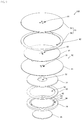
- FIG. 3 is an exploded perspective view of the pump 50 illustrated in FIG. 1 .
- FIG. 4 is a side sectional view of a fluid control device 10 when the pump 50 illustrated in FIG. 1 operates in third-order mode.
- FIG. 5 is an external perspective view of an external structure 27 illustrated in FIG. 4 .
- FIG. 6 is a side sectional view of the fluid control device 10 when the pump 50 illustrated in FIG. 1 operates in first-order mode.
- FIG. 7 is a graph for describing a relationship between the length of a projection portion 12 and vibration amplitude.
- FIG. 8 is a graph for describing a regression line in which the thickness of the projection portion 12 with respect to the length of the projection portion 12 is used as an independent variable.
- FIG. 9 is an exploded perspective view of a fluid control device 10 A according to a second embodiment of the present disclosure.
- FIG. 10 is a side sectional view of the fluid control device 10 A when the pump 50 illustrated in FIG. 9 operates in third-order mode.
- FIG. 11 is a side sectional view of the fluid control device 10 A when the pump 50 illustrated in FIG. 9 operates in first-order mode.
- FIG. 12 is a side sectional view of a fluid control device 10 B when a pump 50 B according to a third embodiment of the present disclosure operates in third-order mode.
- FIG. 13 is a side sectional view of the fluid control device 10 B when the pump 50 B illustrated in FIG. 12 operates in first-order mode.
- FIG. 14 is a side sectional view of a fluid control device 400 according to a fourth embodiment of the present disclosure.
- FIG. 15 is a bottom view of a top portion 415 illustrated in FIG. 14 .
- FIG. 16 is a side sectional view of a fluid control device 500 according to a fifth embodiment of the present disclosure.
- FIG. 17 is a bottom view of a top portion 515 according to a first variation of the top portion 415 illustrated in FIG. 15 .
- FIG. 18 is a bottom view of a top portion 615 according to a second variation of the top portion 415 illustrated in FIG. 15 .
- FIG. 19 is a bottom view of a top portion 715 according to a third variation of the top portion 415 illustrated in FIG. 15 .
- FIG. 20 is an external perspective view of an external structure 127 according to a first variation of the external structure 27 illustrated in FIG. 4 .
- FIG. 21 is an external perspective view of an external structure 227 according to a second variation of the external structure 27 illustrated in FIG. 4 .
- FIG. 22 is a side sectional view of a pump 901 according to a known example.
- a fluid control device can be configured to control a flow of gas or any other fluid, such as liquid, gas-liquid mixed fluid, solid-gas mixed fluid, solid-liquid mixed fluid, gel, and gel-mixed fluid.
- a fluid control device 10 according to a first embodiment of the present disclosure is described below.
- the fluid control device 10 in the first embodiment includes a pump 50 and an external structure 27 , as illustrated in FIG. 5 described below.
- the fluid control device 10 is a suction device for sucking fluid or a discharge device for discharging fluid.
- the fluid control device 10 may constitute, for example, a sphygmomanometer including a cuff, a milking machine, or a nasal aspirator.
- FIG. 1 is an external perspective view of the pump 50 according to the first embodiment of the present disclosure as seen from a bottom surface side.
- FIG. 2 is an external perspective view of the pump 50 illustrated in FIG. 1 as seen from a top surface side.
- FIG. 3 is an exploded perspective view of the pump 50 illustrated in FIG. 1 as seen from the top surface side.
- the pump 50 includes a main portion 11 and a projection portion 12 .
- the main portion 11 is a cylindrical portion having a top surface, a bottom surface, and a peripheral surface.
- the projection portion 12 is an annular portion disposed on an end portion of the main portion 11 near the top surface thereof and projecting from the main portion 11 in an outward direction (circumferential direction) perpendicular to the thickness direction.
- the pump 50 has a vibration space 13 inside the main portion 11 .
- the pump 50 is configured such that a thin top plate 21 , a thick top plate 22 , a side wall plate 23 , a vibration plate 24 , and a piezoelectric element 25 are laminated in sequence from the top surface side to the bottom surface side.
- the thin top plate 21 and thick top plate 22 constitute a “top portion 15 .”
- the piezoelectric element 25 corresponds to a “driver.”
- the thin top plate 21 is disc-shaped, constitutes the top surface of the main portion 11 , and also constitutes the projection portion 12 .
- the thin top plate 21 has channel holes 31 positioned in the vicinity of its center as seen in plan view.
- the number of channel holes 31 is more than one (for example, four in the present embodiment), and they are arranged so as to be locally gathered.
- the channel holes 31 communicate with an external space near the top surface side of the main portion 11 and also communicate with the vibration space 13 inside the main portion 11 .
- the channel holes 31 in the present embodiment are exhaust holes for allowing gas to be ejected to the external space.
- the thick top plate 22 constitutes a part of the main portion 11 and has an annular shape having a smaller circumferential diameter than that of the thin top plate 21 .
- the thick top plate 22 has an opening 32 constituting a part of the vibration space 13 .
- the opening 32 is positioned in the center of the thick top plate 22 as seen in plan view.
- the opening 32 has an opening diameter larger than that of each of the above-described channel holes 31 in the thin top plate 21 and smaller than that of an opening 33 described below in the side wall plate 23 .
- the side wall plate 23 constitutes a part of the main portion 11 and has an annular shape having the same circumferential diameter as that of the thick top plate 22 and having the opening 33 with an opening diameter larger than that of the opening 32 in the thick top plate 22 .
- the opening 33 constitutes a part of the vibration space 13 and is positioned in the center of the thick top plate 22 as seen in plan view.
- the vibration plate 24 includes a frame portion 41 , a vibration member 42 , and a linking portion 43 .
- the vibration member 42 is disc-shaped.
- the frame portion 41 has an annular shape that surrounds the perimeter of the vibration member 42 with a gap interposed therebetween and has the same circumferential diameter and opening diameter as those of the side wall plate 23 .
- the frame portion 41 is joined to the bottom surface of the side wall plate 23 .
- the linking portion 43 has a beam shape radially extending from the vibration member 42 and connecting the vibration member 42 and frame portion 41 .
- the vibration member 42 is elastically supported by the frame portion 41 with the linking portion 43 interposed therebetween.
- the vibration plate 24 has channel holes 34 in a region surrounded by the frame portion 41 , vibration member 42 , and linking portion 43 when the vibration plate 24 is seen in plan view.
- the channel holes 34 communicate with the external space near the bottom surface side of the main portion 11 and also communicate with the vibration space 13 inside the main portion 11 .
- the channel holes 34 in the present embodiment are intake holes for allowing gas to be sucked from the external space.
- the piezoelectric element 25 is disc-shaped and attached to the bottom surface of the vibration member 42 .
- the piezoelectric element 25 includes a disc made of a piezoelectric material, such as a PZT ceramic material, and electrodes (not illustrated) disposed on the upper and lower surfaces of the disc.
- the vibration plate 24 made of metal may be used as the electrode on the upper surface of the piezoelectric element 25 .
- the piezoelectric element 25 has piezoelectricity in which the area is expanded or contracted in the in-plane direction by the application of an electric field in the thickness direction. The use of this piezoelectric element 25 enables an actuator 14 described below to be thin.
- the piezoelectric element 25 may be attached to the top surface of the vibration member 42 or may be disposed on each of both of the top and bottom surfaces of the vibration member 42 , i.e., a total of two piezoelectric elements 25 may be used.
- the multilayer body of the vibration member 42 and piezoelectric element 25 constitutes the “actuator 14 .”
- FIG. 4 is a side sectional view of the fluid control device 10 when the pump 50 illustrated in FIG. 1 operates in third-order mode.
- the dotted lines in FIG. 4 indicate the state in which the actuator 14 and top portion 15 vibrate in third-order mode.
- FIG. 4 also illustrates the state where the pump 50 is mounted on an external structure 27 .
- FIG. 5 is an external perspective view of the external structure 27 illustrated in FIG. 4 .
- the fluid control device 10 includes the pump 50 , external structure 27 , and a housing (not illustrated).
- the pump 50 includes the main portion 11 and projection portion 12 .
- the vibration space 13 is disposed inside the main portion 11 .
- the actuator 14 is arranged on the bottom surface side of the vibration space 13 .
- the external structure 27 is mounted to the housing (not illustrated) of the fluid control device 10 .
- One example of the external structure 27 may have an annular shape, as illustrated in FIG. 5 .
- One example of the material of the external structure 27 may be stainless steel.
- the pump 50 includes the top portion 15 supported by the side wall plate 23 and defining the vibration space 13 with the actuator 14 and side wall plate 23 .
- the top portion 15 includes a top surface portion 110 opposed to the actuator 14 such that a gap is disposed therebetween in the thickness direction, a joint portion 111 extending from the top surface portion 110 in the outward direction and joined to the side wall plate 23 , the projection portion 12 extending from the joint portion 111 in the outward direction and projecting beyond the side wall plate 23 , and a fixation portion 113 extending from the projection portion 12 in the outward direction and fixed to the external structure 27 with the fixation ring 26 interposed therebetween.
- the fixation ring 26 is joined to the fixation portion 113 in a position spaced apart from the main portion 11 in the circumferential direction.
- the pump 50 may be mounted to the external structure 27 without necessarily the fixation ring 26 .
- the thin top plate 21 may be attached directly to the external structure 27 by pressure-bonding or adhesion.
- the fixation portion 113 may be mounted to the external structure 27 by using a screw hole or other similar structure for pressure-bonding created in the fixation portion 113 or adhesive for adhesion applied thereto, or by other similar ways.
- the pump 50 is driven by the application of an alternating-current drive signal to the piezoelectric element 25 .
- the application of the alternating-current drive signal to the piezoelectric element 25 causes area vibration of the piezoelectric element 25 , the area vibration of the piezoelectric element 25 is constrained by the vibration member 42 , and thus concentric flexural vibration occurs in the actuator 14 in the thickness direction.
- the frequency of the alternating-current drive signal is set at a third-order structure resonant frequency of the actuator 14 .
- the third-order structure resonant frequency is a frequency at which the actuator 14 vibrates in third-order mode.
- a first vibration antinode is present in its central portion
- a second vibration antinode whose phase is different from that of the first vibration antinode by 180 degrees is present in its circumferential portion.
- vibration amplitude in the circumferential portion of the actuator 14 is reduced, and the vibration of the actuator 14 does not easily leak to the external structure 27 through the frame portion 41 or other similar elements.
- the vibration of the actuator 14 is transmitted to the thick top plate 22 and thin top plate 21 through the frame portion 41 and side wall plate 23 or through changes in the fluid pressure in the vibration space 13 .
- vibration that causes bending in the thickness direction also occurs in the thin top plate 21 in a region opposed to the opening 32 in the thick top plate 22 .
- the vibration occurring in the thin top plate 21 has the same frequency as that of the vibration occurring in the actuator 14 and has a constant phase difference therefrom.
- the above-described vibrations are successively generated, and the vibrations cause the gap in the vibration space 13 in the thickness direction to change inward along the circumferential direction of the vibration space 13 in a progressive wave manner. This produces a fluid flow inward in the circumferential direction in the vibration space 13 , the fluid is sucked from the channel holes 34 , and the fluid is discharged from the channel holes 31 .
- the top portion 15 in the pump 50 includes the projection portion 12 , which projects beyond the side wall plate 23 in the outward direction.
- the top portion 15 is fixed to the external structure 27 with the fixation portion 113 outside the projection portion 12 .
- the leakage of the vibration in the top portion 15 to the external structure 27 is reduced, in comparison with the case where the top portion 15 is fixed to the external structure 27 in a position opposed to the side wall plate 23 .
- the pump 50 can prevent a reduction in the changes in the gap in the vibration space 13 between the top portion 15 and actuator 14 and can efficiently control the fluid flow in the vibration space 13 .
- the pump 50 can achieve high pump efficiency.
- the frequency of the alternating-current drive signal in FIG. 4 is set at a three-order structure resonant frequency, but it is not limited to this frequency.
- the present disclosure is more useful for the case where the actuator 14 vibrates in first-order mode, as illustrated in FIG. 6 . This is because when the actuator 14 vibrates in first-order mode, the vibration of the actuator 14 in the central position is large and leakage of the vibration from the top portion 15 to the external structure 27 is also large.
- FIG. 7 is a graph that illustrates a relationship between the length of the projection portion 12 and the changes in the gap at the center (one-sided amplitude) of the vibration space 13 .
- the horizontal axis in the graph indicates the distance from the starting point portion of the projection portion 12 (border portion of the projection portion 12 with the main portion 11 ) to the endpoint portion of the projection portion 12 (border portion of the projection portion 12 with the fixation ring 26 ) in the circumferential direction (hereinafter referred to as projection distance d).
- FIG. 7 illustrates a relationship between the projection distance d and normalized amplitude for each of a plurality of samples (legend) with different projection portion thicknesses t.
- the projection distance d and normalized amplitude have a certain correlation. As the projection distance d reduces, the normalized amplitude reduces. As the projection distance d increases, the normalized amplitude approaches 100%. That is, when the projection distance d is short, some of the vibration in the pump 50 leaks to the external structure 27 , and the normalized amplitude is small. When the projection distance d is long, the vibration in the pump 50 does not easily leak to the external structure 27 , and the normalized amplitude is large.
- FIG. 8 is a graph for describing a regression line (regression line that passes through the origin) of the projection distance d calculated based on a plurality of samples from which the same normalized amplitude (90%) is obtainable extracted from the plurality of samples illustrated in FIG. 7 by using the projection portion thickness t as an independent variable.
- the vibration in the pump 50 can be substantially prevented from leaking to the external structure 27 . That is, the changes in the gap at the center of the vibration space 13 in the state where the pump 50 is mounted to the external structure 27 can be virtually equal in magnitude to the changes in the gap at the center of the vibration space 13 in the state where the pump 50 is not mounted to the external structure 27 . Accordingly, by setting the projection distance d of the projection portion 12 such that it satisfies the above-described conditional expression, the pump efficiency of the pump 50 can be enhanced.
- the vibration in the pump 50 can be almost entirely prevented from leaking to the external structure 27 , and the pump efficiency of the pump 50 can be further enhanced.
- the projection distance d of the pump 50 may be set so as to satisfy the following expression. 0.06 ⁇ t (2/3) ⁇ d ⁇ 0.066 ⁇ t (2/3) [Math. 8]
- the projection distance d of the projection portion 12 may be set at a magnitude on the order of approximately 1.1 times the magnitude at which the pump efficiency of the pump 50 is substantially maximized so as to prevent an increase in the size of the pump 50 .
- the pump 50 includes the projection portion 12 , which projects in the outward direction, which is perpendicular to the thickness direction, and fixes the fixation portion 113 to the external structure 27 .
- the pump 50 can suppress the leakage of the vibration occurring in the pump 50 to the external structure 27 . Accordingly, the pump 50 can achieve high pump efficiency.
- FIG. 9 is an exploded perspective view of the fluid control device 10 A according to the second embodiment of the present disclosure.
- FIG. 10 is a side sectional view of the fluid control device 10 A when the pump 50 illustrated in FIG. 9 operates in third-order mode.
- the dotted lines in FIG. 10 indicate the state in which the actuator 14 and top portion 15 vibrate in third-order mode.
- FIG. 11 is a side sectional view of the fluid control device 10 A when the pump 50 illustrated in FIG. 9 operates in first-order mode.
- the dotted lines in FIG. 11 indicate the state in which the actuator 14 and top portion 15 vibrate in first-order mode.
- the fluid control device 10 A includes the pump 50 illustrated in the first embodiment and further includes a valve housing 51 and a valve member 52 .
- the valve housing 51 is laminated on the top surface of the pump 50 and houses the valve member 52 .
- the valve housing 51 includes a valve top plate 53 and a valve frame plate 54 .
- the valve top plate 53 is disc-shaped and constitutes the top surface of the valve housing 51 .
- the valve frame plate 54 is laminated between the valve top plate 53 and the top surface of the pump 50 and has an annular shape in which a valve chamber space 62 for housing the valve member 52 is present.
- the valve member 52 is substantially disc-shaped, is thinner than the valve frame plate 54 , and is vertically movable in the valve chamber space 62 .
- One of the circumferential surface of the valve member 52 and the inner wall surface defining the valve chamber space 62 has a depression and the other has a protrusion so that they are engaged with each other, and the valve member 52 is not rotatable in the valve chamber space 62 .
- the valve top plate 53 has channel holes 61 positioned in the vicinity of the center as seen in plan view.
- the channel holes 61 communicate with an external space near the top surface side of the valve housing 51 and also communicate with the valve chamber space 62 inside the valve housing 51 .
- the channel holes 61 are arranged in positions displaced from the channel holes 31 in the thin top plate 21 in the pump 50 so as not to be opposed thereto.
- the valve member 52 has channel holes 63 positioned in the vicinity of the center as seen in plan view.
- the channel holes 63 are arranged in positions opposed to the channel holes 61 in the valve top plate 53 . That is, the channel holes 63 in the valve member 52 are arranged in positions displaced from the channel holes 31 in the thin top plate 21 in the pump 50 so as not to be opposed thereto, as in the case of the channel holes 61 in the valve top plate 53 .
- the pump 50 discharges fluid to the valve chamber space 62 .
- the fluid pressure on the bottom surface side of the valve member 52 in the valve chamber space 62 is increased, and the valve member 52 moves toward the valve top plate 53 .
- the channel holes 63 in the valve member 52 overlap the channel holes 61 in the valve top plate 53 , a path for fluid is opened in the valve housing 51 .
- the fluid is discharged through the channel holes 63 in the valve member 52 and the channel holes 61 in the valve top plate 53 to the external space.
- the fluid pressure in the pump 50 is reduced because, for example, the pump 50 stops being driven and the fluid pressure in the external space on the top surface side of the valve housing 51 is relatively increased, the fluid is about to flow in the opposite direction from the external space through the channel holes 61 in the valve top plate 53 toward the valve chamber space 62 .
- the fluid being about to flow in the opposite direction from the external space toward the valve chamber space 62 increases the fluid pressure on the top surface side of the valve member 52 in the valve chamber space 62 , and the valve member 52 moves toward the pump 50 .
- the channel holes 63 in the valve member 52 do not overlap the channel holes 31 in the pump 50 and are closed, and backflow of the fluid from the external space to the valve chamber space 62 is prevented.
- the top portion 15 in the pump 50 includes the projection portion 12 , which projects beyond the side wall plate 23 in the outward direction.
- the above-described valve housing 51 constitutes “external structure” with respect to the pump 50 . That is, the fluid control device 10 A includes the valve housing 51 , in place of the fixation ring 26 and external structure 27 illustrated in the first embodiment.
- the top portion 15 is fixed to the valve housing 51 with the fixation portion 113 outside the projection portion 12 .
- the pump 50 can more suppress the leakage of the vibration occurring in the pump 50 to the valve housing 51 , in comparison with the case where the pump 50 is fixed to the valve housing 51 in a position opposed to the side wall plate 23 .
- the pump 50 can prevent a reduction in the changes in the gap in the vibration space 13 between the top portion 15 and actuator 14 and can efficiently control the fluid flow in the vibration space 13 .
- the pump 50 can achieve high pump efficiency.
- FIG. 12 is a side sectional view of the fluid control device 10 B when a pump 50 B according to the third embodiment of the present disclosure operates in third-order mode.
- the dotted lines in FIG. 10 indicate the state in which the actuator 14 and top portion 15 B vibrate in third-order mode.
- FIG. 13 is a side sectional view of the fluid control device 10 B when the pump 50 B illustrated in FIG. 12 operates in first-order mode. The dotted lines in FIG. 13 indicate the state in which the actuator 14 and top portion 15 B vibrate in first-order mode.
- the fluid control device 10 B includes the pump 50 B having a configuration different from that in the pump 50 illustrated in the second embodiment.
- the pump 50 B includes a thick top plate 22 B.
- the circumferential diameter of the thick top plate 22 B is larger than that of each of the side wall plate 23 and vibration plate 24 and smaller than that of the thin top plate 21 .
- the top portion 15 in the pump 50 B includes the projection portion 12 , which projects beyond the side wall plate 23 in the outward direction.
- the valve housing 51 constitutes “external structure” with respect to the pump 50 B. That is, the fluid control device 10 B includes the valve housing 51 , in place of the fixation ring 26 and external structure 27 illustrated in the first embodiment.
- the top portion 15 is fixed to the valve housing 51 with the fixation portion 113 outside the projection portion 12 .
- the pump 50 B can more suppress the leakage of the vibration occurring in the pump 50 B to the valve housing 51 , in comparison with the case where the pump 50 B is fixed to the valve housing 51 in a position opposed to the side wall plate 23 .
- the pump 50 B can prevent a reduction in the changes in the gap in the vibration space 13 between the top portion 15 and actuator 14 and can efficiently control the fluid flow in the vibration space 13 .
- the pump 50 B can achieve high pump efficiency.
- the vibration leaks more easily from the pump 50 B to the valve housing 51 through the projection portion 12 .
- the projection distance of the thin top plate 21 from the thick top plate 22 B can be further increased or that the thickness of the thin top plate 21 can be further reduced.
- FIG. 14 is a side sectional view of the fluid control device 400 according to the fourth embodiment of the present disclosure.
- the dotted lines in FIG. 14 indicate the state in which the actuator 14 and top portion 415 vibrate in first-order mode.
- FIG. 15 is a bottom view of the top portion 415 illustrated in FIG. 14 .
- the fluid control device 400 in the fourth embodiment differs from the fluid control device 10 in the first embodiment in that it includes a pump 450 .
- the pump 450 differs from the pump 50 in that the top portion 415 is made up of the thin top plate 21 , thick top plate 22 , and an annular frame plate 423 .
- the top portion 415 includes the top surface portion 110 , joint portion 111 , projection portion 12 , and a fixation portion 413 .
- the other configuration is the same and is not described here.
- the frame plate 423 is joined to the bottom surface in a region in the thin top plate 21 fixed to the external structure 27 with the fixation ring 26 interposed therebetween.
- the thickness of the fixation portion 413 is larger than that of the fixation portion 113 .
- the projection portion 12 includes a thin portion 211 being thinner than the joint portion 111 .
- the thin portion 211 is annular.
- the thin portion 211 corresponds to an example of a first thin portion in the present disclosure.
- the top portion 415 in the pump 50 includes the projection portion 12 , which projects beyond the side wall plate 23 in the outward direction.
- the top portion 415 is fixed to the external structure 27 with the fixation portion 413 outside the projection portion 12 .
- the pump 50 can more suppress the leakage of the vibration occurring in the pump 50 to the external structure 27 , in comparison with the case where the pump 50 is fixed to the external structure 27 in a position opposed to the side wall plate 23 .
- the pump 50 can prevent a reduction in the changes in the gap in the vibration space 13 between the top portion 415 and actuator 14 and can efficiently control the fluid flow in the vibration space 13 .
- the pump 50 can achieve high pump efficiency.
- the pump 50 can have a reduced stiffness of the projection portion 12 . Hence, the pump 50 can more suppress the leakage of the vibration occurring in the pump 50 to the external structure 27 through the projection portion 12 .
- the pump 450 in FIG. 14 operates in first-order mode, but it is not limited to that configuration. In practice, the pump 450 may operate in third-order mode.
- FIG. 16 is a side sectional view of the fluid control device 500 according to the fifth embodiment of the present disclosure.
- the fluid control device 500 in the fifth embodiment differs from the fluid control device 400 in the fourth embodiment in how the pump 450 is fixed.
- the bottom surface of the fixation portion 413 in the pump 450 is fixed to the external structure 27 with the fixation ring 26 interposed therebetween.
- the other configuration is the same and is not described here.
- the pump 450 in the fluid control device 400 and fluid control device 500 operates, the atmospheric pressure and the pressure of the vibration space 13 are applied to both surfaces of the top portion 415 . While the pump 450 operates, the pressure of the vibration space 13 is higher than the atmospheric pressure.
- the top surface (i.e., a surface with a lower pressure) of the fixation portion 413 in the pump 450 illustrated in FIG. 14 can be fixed to the external structure 27 with the fixation ring 26 interposed therebetween.
- Example variations described below can be used as the top portion 415 illustrated in FIG. 15 .
- FIG. 17 is a bottom view of a top portion 515 according to a first variation of the top portion 415 illustrated in FIG. 15 .
- FIG. 18 is a bottom view of a top portion 615 according to a second variation of the top portion 415 illustrated in FIG. 15 .
- FIG. 19 is a bottom view of a top portion 715 according to a third variation of the top portion 415 illustrated in FIG. 15 .
- the top portion 515 illustrated in FIG. 17 and the top portion 615 illustrated in FIG. 18 differ from the top portion 415 in that they have different proportions of the thin portion 211 in the projection portion 12 .
- the other configuration is the same and is not described here.
- the projection portion 12 is annular and the thin portion 211 is arranged in an annular shape, the symmetry of the vibration in the top portion 415 is maintained. Thus, unnecessary vibration does not easily occur in the top portion 415 , and an energy loss is lessened.
- the stiffness of the projection portion 12 in the pump 50 can be more reduced.
- the pump 50 can more suppress the leakage of the vibration occurring in the pump 50 to the external structure 27 .
- the proportion of the thin portion 211 in the projection portion 12 can be equal to or larger than 50%, as illustrated in FIG. 18 .
- the proportion of the thin portion 211 in the portion 12 can be equal to or larger than 80%, as illustrated in FIG. 17 .
- the proportion of the thin portion 211 in the portion 12 can be equal to 100%, as illustrated in FIG. 15 .
- the projection portion 12 includes the annular thin portion 211 , but it is not limited to this configuration.
- the thin portion 211 may have a shape other than the annular shape (e.g., a polygonal ring shape).
- the top portion 715 illustrated in FIG. 19 differs from the top portion 415 in that it includes a projection portion 712 .
- the other configuration is the same and is not described here.
- the projection portion 712 includes the thin portion 211 , which is thinner than the joint portion 111 , and a thin portion 212 being thinner than the joint portion 111 .
- the thin portion 211 is annular.
- the thin portion 212 is also annular. The distance from the central axis C of the top surface portion 110 to the thin portion 211 is different from the distance from that to the thin portion 212 .
- the thin portion 211 corresponds to one example of a first thin portion in the present disclosure.
- the thin portion 212 corresponds to one example of a second thin portion in the present disclosure.
- the projection portion 12 can have no opening.
- the pump 50 can separate the spaces above and below the top portion 415 , 515 , 615 , and 715 from each other.
- the pump 50 can confine the path for fluid to the vibration space 13 and can precisely control the fluid.
- FIG. 20 is an external perspective view of an external structure 127 according to a first variation of the external structure 27 illustrated in FIG. 4 .
- FIG. 21 is an external perspective view of an external structure 227 according to a second variation of the external structure 27 illustrated in FIG. 4 .
- the external structure 127 illustrated in FIG. 20 differs from the external structure 27 illustrated in FIG. 4 in that it includes a reinforcement portion 129 .
- the external structure 127 includes a ring-shaped portion 128 to be joined to the fixation portion 113 in the pump 50 and the reinforcement portion 129 , which is positioned inside the ring-shaped portion 128 .
- the other configuration is the same and is not described here.
- the stiffness of the external structure 127 is increased by the reinforcement portion 129 , the vibration of the external structure 127 is suppressed.
- transmission of the vibration occurring in the pump 50 to a housing (not illustrated) of the fluid control device 10 through the external structure 127 can be significantly reduced.
- the external structure 227 illustrated in FIG. 21 differs from the external structure 27 illustrated in FIG. 4 in that it includes a reinforcement portion 229 .
- the external structure 227 includes the ring-shaped portion 128 to be joined to the fixation portion 113 in the pump 50 and the reinforcement portion 229 , which is positioned inside the ring-shaped portion 128 .
- the other configuration is the same and is not described here.
- the stiffness of the external structure 227 is increased by the reinforcement portion 229 , the vibration of the external structure 227 is suppressed.
- transmission of the vibration occurring in the pump 50 to the housing (not illustrated) of the fluid control device 10 through the external structure 227 can be significantly reduced.
- each of the external structure 27 and ring-shaped portion 128 is annular, but it is not limited to this shape. In practice, each of the external structure 27 and ring-shaped portion 128 may have a shape other than the annular shape (e.g., a polygonal ring shape).
- the piezoelectric element is disposed as the driving source for the pump.
- the present disclosure is not limited to this example.
- the pump may be configured to perform pumping by electromagnetic driving.
- the piezoelectric element 25 is made of a PZT ceramic material.
- the piezoelectric element 25 may be made of another piezoelectric material, such as a non-lead piezoelectric ceramic material, for example, potassium sodium niobate-based or alkali niobate-based ceramic material.
- the piezoelectric element is joined to a principal surface of the vibration plate opposite the vibration space.
- the present disclosure is not limited to this example.
- the piezoelectric element may be joined to a principal surface of the vibration plate near the vibration space.
- Two piezoelectric elements may be joined to both principal surfaces of the vibration plate.
- the piezoelectric element, vibration plate, vibration space, and other element are arranged in a circular shape as seen in plan view.
- the present disclosure is not limited to this example.
- the shape may be a rectangle or polygon.
- the actuator is driven at a third-order resonant frequency.
- the present disclosure is not limited to this example.
- the actuator may be driven at a first-order resonant frequency or other resonant frequency.
- the plurality of circular channel holes are gathered in the vicinity of the center of the top portion, valve casing, and valve member.
- the present disclosure is not limited to this example.
- one channel hole may be disposed, one or more noncircular channel holes may be disposed, or one or more channel holes extending in the outward direction may be disposed in the side wall plate.
- the depression portion is disposed in the vibration space in the vicinity of the channel holes on the top portion side.
- the present disclosure is not limited to this example.
- the depression portion may not be disposed.
- the top portion is configured as a multilayer body of the thin top plate and thick top plate.
- the present disclosure is not limited to this example.
- the top portion having the above-described shape may be configured as a single-piece member.
- the top portion may be configured with a uniform thickness as the whole.
Landscapes
- Engineering & Computer Science (AREA)
- Mechanical Engineering (AREA)
- General Engineering & Computer Science (AREA)
- Reciprocating Pumps (AREA)
Applications Claiming Priority (3)
| Application Number | Priority Date | Filing Date | Title |
|---|---|---|---|
| JP2015095446 | 2015-05-08 | ||
| JP2015-095446 | 2015-05-08 | ||
| PCT/JP2016/063136 WO2016181833A1 (ja) | 2015-05-08 | 2016-04-27 | ポンプ、流体制御装置 |
Related Parent Applications (1)
| Application Number | Title | Priority Date | Filing Date |
|---|---|---|---|
| PCT/JP2016/063136 Continuation WO2016181833A1 (ja) | 2015-05-08 | 2016-04-27 | ポンプ、流体制御装置 |
Publications (2)
| Publication Number | Publication Date |
|---|---|
| US20180051686A1 US20180051686A1 (en) | 2018-02-22 |
| US10697450B2 true US10697450B2 (en) | 2020-06-30 |
Family
ID=57248880
Family Applications (1)
| Application Number | Title | Priority Date | Filing Date |
|---|---|---|---|
| US15/800,683 Active US10697450B2 (en) | 2015-05-08 | 2017-11-01 | Pump having a top portion fixed to an external structure |
Country Status (5)
| Country | Link |
|---|---|
| US (1) | US10697450B2 (zh) |
| JP (1) | JP6394801B2 (zh) |
| CN (1) | CN107532584B (zh) |
| GB (1) | GB2554231B (zh) |
| WO (1) | WO2016181833A1 (zh) |
Cited By (4)
| Publication number | Priority date | Publication date | Assignee | Title |
|---|---|---|---|---|
| US20210324844A1 (en) * | 2019-03-27 | 2021-10-21 | Murata Manufacturing Co., Ltd. | Piezoelectric pump |
| US20210332812A1 (en) * | 2019-03-27 | 2021-10-28 | Murata Manufacturing Co., Ltd. | Piezoelectric pump |
| EP4074353A1 (en) | 2006-04-14 | 2022-10-19 | DEKA Products Limited Partnership | Diaphragm, pump and pump cassette |
| TWI797853B (zh) * | 2021-11-29 | 2023-04-01 | 研能科技股份有限公司 | 氣體傳輸裝置 |
Families Citing this family (9)
| Publication number | Priority date | Publication date | Assignee | Title |
|---|---|---|---|---|
| CN108278196B (zh) * | 2017-01-05 | 2022-05-17 | 研能科技股份有限公司 | 流体控制装置 |
| WO2018221287A1 (ja) * | 2017-05-31 | 2018-12-06 | 株式会社村田製作所 | バルブおよび流体制御装置 |
| TWI646262B (zh) * | 2017-10-27 | 2019-01-01 | 研能科技股份有限公司 | 氣體輸送裝置 |
| WO2019151173A1 (ja) * | 2018-01-30 | 2019-08-08 | 株式会社村田製作所 | 流体制御装置 |
| JP6973615B2 (ja) | 2018-02-13 | 2021-12-01 | 株式会社村田製作所 | 流体制御装置 |
| JP6952400B2 (ja) * | 2018-05-15 | 2021-10-20 | 京セラ株式会社 | 圧電ガスポンプ |
| WO2019230189A1 (ja) * | 2018-05-29 | 2019-12-05 | 株式会社村田製作所 | 流体制御装置 |
| WO2020111063A1 (ja) | 2018-11-27 | 2020-06-04 | 株式会社村田製作所 | ポンプ |
| CN115702291A (zh) * | 2020-06-23 | 2023-02-14 | 株式会社村田制作所 | 致动器和流体控制装置 |
Citations (12)
| Publication number | Priority date | Publication date | Assignee | Title |
|---|---|---|---|---|
| US4864918A (en) * | 1986-11-07 | 1989-09-12 | The Gates Rubber Company | Thermoplastic diaphragm |
| US5145336A (en) * | 1990-03-13 | 1992-09-08 | Knf Neuberger Gmbh | Diaphragm pump with reinforced diaphragm |
| US20090010780A1 (en) * | 2006-03-29 | 2009-01-08 | Murata Manufacturing Co., Ltd. | Micropump |
| US20090148320A1 (en) * | 2006-03-07 | 2009-06-11 | Influent Corporation | Fluidic Energy Transfer Devices |
| JP2009250132A (ja) | 2008-04-07 | 2009-10-29 | Sony Corp | 冷却装置及び電子機器 |
| JP2012107636A (ja) | 2012-03-12 | 2012-06-07 | Murata Mfg Co Ltd | 圧電マイクロポンプ |
| US20130071269A1 (en) * | 2009-10-01 | 2013-03-21 | Murata Manufacturing Co., Ltd. | Piezoelectric micro-blower |
| JP2013169374A (ja) | 2012-02-22 | 2013-09-02 | Murata Mfg Co Ltd | 送液システム |
| US20130255801A1 (en) | 2010-12-24 | 2013-10-03 | Murata Manufacturing Co., Ltd. | Fluid supply device |
| US20140028153A1 (en) * | 2012-07-27 | 2014-01-30 | Samsung Electro-Mechanics Co., Ltd | Vibration actuator |
| US20140044568A1 (en) | 2011-04-28 | 2014-02-13 | Commissariat A L'energie Atomique Et Aux Ene Alt | Micropump having a flowmeter, and method for producing same |
| WO2014024608A1 (ja) | 2012-08-10 | 2014-02-13 | 株式会社村田製作所 | ブロア |
Family Cites Families (1)
| Publication number | Priority date | Publication date | Assignee | Title |
|---|---|---|---|---|
| JP4873014B2 (ja) * | 2006-12-09 | 2012-02-08 | 株式会社村田製作所 | 圧電マイクロブロア |
-
2016
- 2016-04-27 CN CN201680025549.3A patent/CN107532584B/zh active Active
- 2016-04-27 GB GB1716987.1A patent/GB2554231B/en active Active
- 2016-04-27 WO PCT/JP2016/063136 patent/WO2016181833A1/ja active Application Filing
- 2016-04-27 JP JP2017517875A patent/JP6394801B2/ja active Active
-
2017
- 2017-11-01 US US15/800,683 patent/US10697450B2/en active Active
Patent Citations (14)
| Publication number | Priority date | Publication date | Assignee | Title |
|---|---|---|---|---|
| US4864918A (en) * | 1986-11-07 | 1989-09-12 | The Gates Rubber Company | Thermoplastic diaphragm |
| US5145336A (en) * | 1990-03-13 | 1992-09-08 | Knf Neuberger Gmbh | Diaphragm pump with reinforced diaphragm |
| US20090148320A1 (en) * | 2006-03-07 | 2009-06-11 | Influent Corporation | Fluidic Energy Transfer Devices |
| US20090010780A1 (en) * | 2006-03-29 | 2009-01-08 | Murata Manufacturing Co., Ltd. | Micropump |
| JP2009250132A (ja) | 2008-04-07 | 2009-10-29 | Sony Corp | 冷却装置及び電子機器 |
| US20130071269A1 (en) * | 2009-10-01 | 2013-03-21 | Murata Manufacturing Co., Ltd. | Piezoelectric micro-blower |
| US20130255801A1 (en) | 2010-12-24 | 2013-10-03 | Murata Manufacturing Co., Ltd. | Fluid supply device |
| JP2014066364A (ja) | 2010-12-24 | 2014-04-17 | Murata Mfg Co Ltd | 流体供給装置 |
| US20140044568A1 (en) | 2011-04-28 | 2014-02-13 | Commissariat A L'energie Atomique Et Aux Ene Alt | Micropump having a flowmeter, and method for producing same |
| JP2013169374A (ja) | 2012-02-22 | 2013-09-02 | Murata Mfg Co Ltd | 送液システム |
| JP2012107636A (ja) | 2012-03-12 | 2012-06-07 | Murata Mfg Co Ltd | 圧電マイクロポンプ |
| US20140028153A1 (en) * | 2012-07-27 | 2014-01-30 | Samsung Electro-Mechanics Co., Ltd | Vibration actuator |
| WO2014024608A1 (ja) | 2012-08-10 | 2014-02-13 | 株式会社村田製作所 | ブロア |
| JP5692468B2 (ja) | 2012-08-10 | 2015-04-01 | 株式会社村田製作所 | ブロア |
Non-Patent Citations (3)
| Title |
|---|
| Chinese Office Action for Application No. 201680025549.3 dated Aug. 29, 2018. |
| International Search report issued in PCT/JP2016/063136 dated Aug. 2, 2016. |
| Written Opinion issued in PCT/JP2016/063136 dated Aug. 2, 2016. |
Cited By (7)
| Publication number | Priority date | Publication date | Assignee | Title |
|---|---|---|---|---|
| EP4074353A1 (en) | 2006-04-14 | 2022-10-19 | DEKA Products Limited Partnership | Diaphragm, pump and pump cassette |
| US20210324844A1 (en) * | 2019-03-27 | 2021-10-21 | Murata Manufacturing Co., Ltd. | Piezoelectric pump |
| US20210332812A1 (en) * | 2019-03-27 | 2021-10-28 | Murata Manufacturing Co., Ltd. | Piezoelectric pump |
| US11867167B2 (en) * | 2019-03-27 | 2024-01-09 | Murata Manufacturing Co., Ltd. | Piezoelectric pump with annular valve arrangement |
| US11867166B2 (en) * | 2019-03-27 | 2024-01-09 | Murata Manufacturing Co., Ltd. | Piezoelectric pump with annular valve arrangement |
| TWI797853B (zh) * | 2021-11-29 | 2023-04-01 | 研能科技股份有限公司 | 氣體傳輸裝置 |
| US11746770B2 (en) | 2021-11-29 | 2023-09-05 | Microjet Technology Co., Ltd. | Gas transportation device |
Also Published As
| Publication number | Publication date |
|---|---|
| US20180051686A1 (en) | 2018-02-22 |
| JPWO2016181833A1 (ja) | 2017-12-07 |
| GB201716987D0 (en) | 2017-11-29 |
| WO2016181833A1 (ja) | 2016-11-17 |
| JP6394801B2 (ja) | 2018-09-26 |
| CN107532584B (zh) | 2019-12-27 |
| GB2554231A (en) | 2018-03-28 |
| CN107532584A (zh) | 2018-01-02 |
| GB2554231B (en) | 2020-12-02 |
Similar Documents
| Publication | Publication Date | Title |
|---|---|---|
| US10697450B2 (en) | Pump having a top portion fixed to an external structure | |
| US11661935B2 (en) | Blower | |
| US10280915B2 (en) | Fluid control device | |
| US10428812B2 (en) | Disc pump with advanced actuator | |
| CN112204256B (zh) | 泵 | |
| CN108317093B (zh) | 鼓风机 | |
| US10738773B2 (en) | Blower | |
| US10794378B2 (en) | Fluid control device, decompression device, and compression device | |
| WO2019124060A1 (ja) | ポンプ | |
| US8821134B2 (en) | Fluid disc pump | |
| JP6575634B2 (ja) | ブロア | |
| US10125760B2 (en) | Pump | |
| US11879449B2 (en) | Piezoelectric pump with vibrating plate, protrusion and valve arrangement | |
| US11300115B2 (en) | Pump and fluid control device | |
| JP2023126991A (ja) | ポンプ及び流体制御装置 |
Legal Events
| Date | Code | Title | Description |
|---|---|---|---|
| AS | Assignment |
Owner name: MURATA MANUFACTURING CO., LTD., JAPAN Free format text: ASSIGNMENT OF ASSIGNORS INTEREST;ASSIGNORS:TANAKA, NOBUHIRA;KONDO, DAISUKE;REEL/FRAME:044008/0854 Effective date: 20171025 |
|
| FEPP | Fee payment procedure |
Free format text: ENTITY STATUS SET TO UNDISCOUNTED (ORIGINAL EVENT CODE: BIG.); ENTITY STATUS OF PATENT OWNER: LARGE ENTITY |
|
| STPP | Information on status: patent application and granting procedure in general |
Free format text: RESPONSE TO NON-FINAL OFFICE ACTION ENTERED AND FORWARDED TO EXAMINER |
|
| STPP | Information on status: patent application and granting procedure in general |
Free format text: NON FINAL ACTION MAILED |
|
| STPP | Information on status: patent application and granting procedure in general |
Free format text: RESPONSE TO NON-FINAL OFFICE ACTION ENTERED AND FORWARDED TO EXAMINER |
|
| STPP | Information on status: patent application and granting procedure in general |
Free format text: FINAL REJECTION MAILED |
|
| STPP | Information on status: patent application and granting procedure in general |
Free format text: RESPONSE AFTER FINAL ACTION FORWARDED TO EXAMINER |
|
| STPP | Information on status: patent application and granting procedure in general |
Free format text: DOCKETED NEW CASE - READY FOR EXAMINATION |
|
| STPP | Information on status: patent application and granting procedure in general |
Free format text: NOTICE OF ALLOWANCE MAILED -- APPLICATION RECEIVED IN OFFICE OF PUBLICATIONS |
|
| STPP | Information on status: patent application and granting procedure in general |
Free format text: NOTICE OF ALLOWANCE MAILED -- APPLICATION RECEIVED IN OFFICE OF PUBLICATIONS |
|
| STCF | Information on status: patent grant |
Free format text: PATENTED CASE |
|
| MAFP | Maintenance fee payment |
Free format text: PAYMENT OF MAINTENANCE FEE, 4TH YEAR, LARGE ENTITY (ORIGINAL EVENT CODE: M1551); ENTITY STATUS OF PATENT OWNER: LARGE ENTITY Year of fee payment: 4 |