US10696230B2 - Rearview unit with clutch for automated tilt mechanism - Google Patents
Rearview unit with clutch for automated tilt mechanism Download PDFInfo
- Publication number
- US10696230B2 US10696230B2 US16/006,068 US201816006068A US10696230B2 US 10696230 B2 US10696230 B2 US 10696230B2 US 201816006068 A US201816006068 A US 201816006068A US 10696230 B2 US10696230 B2 US 10696230B2
- Authority
- US
- United States
- Prior art keywords
- plate
- socket
- substrate
- input element
- clutch plate
- Prior art date
- Legal status (The legal status is an assumption and is not a legal conclusion. Google has not performed a legal analysis and makes no representation as to the accuracy of the status listed.)
- Active
Links
Images





Classifications
-
- B—PERFORMING OPERATIONS; TRANSPORTING
- B60—VEHICLES IN GENERAL
- B60R—VEHICLES, VEHICLE FITTINGS, OR VEHICLE PARTS, NOT OTHERWISE PROVIDED FOR
- B60R1/00—Optical viewing arrangements; Real-time viewing arrangements for drivers or passengers using optical image capturing systems, e.g. cameras or video systems specially adapted for use in or on vehicles
- B60R1/02—Rear-view mirror arrangements
- B60R1/04—Rear-view mirror arrangements mounted inside vehicle
-
- B—PERFORMING OPERATIONS; TRANSPORTING
- B60—VEHICLES IN GENERAL
- B60R—VEHICLES, VEHICLE FITTINGS, OR VEHICLE PARTS, NOT OTHERWISE PROVIDED FOR
- B60R1/00—Optical viewing arrangements; Real-time viewing arrangements for drivers or passengers using optical image capturing systems, e.g. cameras or video systems specially adapted for use in or on vehicles
- B60R1/12—Mirror assemblies combined with other articles, e.g. clocks
-
- F—MECHANICAL ENGINEERING; LIGHTING; HEATING; WEAPONS; BLASTING
- F16—ENGINEERING ELEMENTS AND UNITS; GENERAL MEASURES FOR PRODUCING AND MAINTAINING EFFECTIVE FUNCTIONING OF MACHINES OR INSTALLATIONS; THERMAL INSULATION IN GENERAL
- F16H—GEARING
- F16H19/00—Gearings comprising essentially only toothed gears or friction members and not capable of conveying indefinitely-continuing rotary motion
- F16H19/001—Gearings comprising essentially only toothed gears or friction members and not capable of conveying indefinitely-continuing rotary motion for conveying reciprocating or limited rotary motion
-
- B—PERFORMING OPERATIONS; TRANSPORTING
- B60—VEHICLES IN GENERAL
- B60R—VEHICLES, VEHICLE FITTINGS, OR VEHICLE PARTS, NOT OTHERWISE PROVIDED FOR
- B60R1/00—Optical viewing arrangements; Real-time viewing arrangements for drivers or passengers using optical image capturing systems, e.g. cameras or video systems specially adapted for use in or on vehicles
- B60R1/12—Mirror assemblies combined with other articles, e.g. clocks
- B60R2001/1215—Mirror assemblies combined with other articles, e.g. clocks with information displays
-
- B—PERFORMING OPERATIONS; TRANSPORTING
- B60—VEHICLES IN GENERAL
- B60R—VEHICLES, VEHICLE FITTINGS, OR VEHICLE PARTS, NOT OTHERWISE PROVIDED FOR
- B60R1/00—Optical viewing arrangements; Real-time viewing arrangements for drivers or passengers using optical image capturing systems, e.g. cameras or video systems specially adapted for use in or on vehicles
- B60R1/12—Mirror assemblies combined with other articles, e.g. clocks
- B60R2001/1253—Mirror assemblies combined with other articles, e.g. clocks with cameras, video cameras or video screens
Definitions
- the present disclosure relates generally to a full-display rearview mirror for a motor vehicle and, more particularly, relates to a mechanism for automatic movement of the display mirror substrate between active and inactive positions.
- a rearview mirror for a vehicle includes a substrate having a reflective surface thereon and an actuation mechanism coupled within the substrate.
- the actuation mechanism includes a socket plate rotatably coupled within the cavity of the housing at a first end thereof and extending to a second end and a link element rotatably coupled within the cavity of the housing adjacent the second end of the socket and engaged with the socket plate to rotate the socket plate about the first end by rotation of the link element.
- the actuation mechanism further includes a clutch plate rigidly coupled with the link element about an axis thereof and an input element positioned on, rotatable about, and slideable along the axis of the link element. The input element releasably engages the clutch plate under a force applied thereto along the axis.
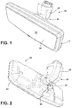
- FIG. 1 is a front perspective view of a rearview mirror including an actuation mechanism according to an aspect of the disclosure
- FIG. 2 is a back perspective view of the rearview mirror of FIG. 1 ;
- FIG. 3 is a perspective view of an interior of a vehicle incorporating the rearview mirror of claim 1 into a rear-vision system for the vehicle;
- FIG. 4 is an exploded view of the rearview mirror of FIG. 1 ;
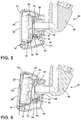
- FIG. 5 is a cross-section view of the rearview mirror of FIG. 1 with the actuation mechanism thereof in a first position;
- FIG. 6 is a cross-section view of the rearview mirror of FIG. 1 with the actuation mechanism thereof in a second position;
- FIG. 7 is a front perspective view of the actuation mechanism
- FIG. 8 is a back perspective view of the actuation mechanism
- FIG. 9 is an exploded view of the actuation mechanism
- FIG. 10 is a perspective view of a drivetrain of the actuation mechanism
- FIG. 11 is a detail perspective view of a clutch mechanism of the drivetrain
- FIG. 12 is a perspective view of the actuation mechanism and the drivetrain in a first configuration
- FIG. 13 is a detail perspective view of the clutch mechanism in a first over-rotated condition corresponding with the first configuration
- FIG. 14 is a perspective view of the actuation mechanism and the drivetrain in a second configuration
- FIG. 15 is a detail perspective view of the clutch mechanism in a second over-rotated condition corresponding with the second configuration
- FIG. 16 is a back perspective view of an alternative actuation mechanism according to further aspects of the disclosure.
- FIG. 17 is a partially exploded view of the actuation mechanism of FIG. 15 ;
- FIG. 18 is detail view of a portion of a clutch assembly of the actuation mechanism.
- FIG. 19 is detail cross-section view of a portion of the clutch assembly of the actuation mechanism.
- FIG. 20 is a back perspective view of an alternative actuation mechanism according to further aspects of the disclosure.
- FIG. 21 is an detail perspective view showing internal components of the actuation mechanism
- FIG. 22 is a further detail perspective view showing additional internal components of the actuation mechanism.
- FIG. 23 is a further detail perspective view showing additional internal components of the actuation mechanism.
- the terms “upper,” “lower,” “right,” “left,” “rear,” “front,” “vertical,” “horizontal,” and derivatives thereof shall relate to the device as oriented in FIG. 1 .
- the device may assume various alternative orientations and step sequences, except where expressly specified to the contrary.
- the specific devices and processes illustrated in the attached drawings, and described in the following specification are simply exemplary embodiments of the inventive concepts defined in the appended claims. Hence, specific dimensions and other physical characteristics relating to the embodiments disclosed herein are not to be considered as limiting, unless the claims expressly state otherwise.
- reference numeral 10 generally designates a rearview mirror for a vehicle 12 .
- Rearview mirror 10 includes a substrate 20 having a reflective surface 22 thereon, and an actuation mechanism 24 coupled with the substrate 20 .
- Actuation mechanism 24 includes a socket plate 26 rotatably coupled with substrate 20 a first end 28 thereof and extending to a second end 30 , and a link element 32 rotatably coupled within the cavity 16 of the housing 14 adjacent the second end 30 of the socket plate 26 and engaged with the socket plate 26 to rotate the socket plate 26 about the first end 28 by rotation of the link element 32 .
- Actuation mechanism 24 further includes a clutch plate 34 rigidly coupled with the link element 32 about an axis 36 thereof and an input element 38 positioned on, rotatable about, and slideable along the axis 36 of the link element 32 , the input element 38 releasably engaging the clutch plate 34 under a force applied thereto along the axis 36 .
- rearview mirror 10 can be used in connection with interior of vehicle 12 , including as a portion of a rearview vision system.
- substrate 20 can include a video display screen along a portion or an entirety thereof such that rearview mirror 10 is what may be referred to as a “display” or a “full display” mirror.
- Substrate 20 when including such a display, is referred to herein as “display substrate” 20 and may be capable of displaying an image replicating that which would be available from a typical reflective mirror by receiving an image from an appropriately-positioned video camera 42 or the like when the display is in an “active” state. Such an image can be supplemented with other information presented on display substrate 20 .
- reflective surface 22 may be applied thereover as a coating or separate element having properties of a one-way mirror to both provide a reflected image as well as to permit the video image of display substrate 20 to be visible therethrough.
- rearview mirror 10 can be electronically connected with camera 42 by electronic circuitry 44 within vehicle 12 .
- control circuitry 44 can be provided to both cause display substrate 20 to display the image from camera 42 and to implement corresponding movement of substrate 20 by way of control of the actuation mechanism 24 , as described in further detail herein.
- Circuitry 44 can further be connected with an on-board computer 46 to, for example, receive information regarding a state of the vehicle 12 , for use by circuitry 44 , as also discussed further below.
- actuation mechanism 24 can move substrate 20 about a mounting arm 48 that secures rearview mirror 10 within the interior 40 of vehicle 12 by rotation of substrate 20 about first end 28 of socket plate 26 ( FIG. 4 ), which is coupled with mounting arm 48 .
- Such movement can be useful to position substrate 20 according to whether or not the display is in an off state or an on state. In this manner, when display substrate 20 is in an inactive state (when the display is “off” or when no image is otherwise presented thereon), as depicted in FIG.
- reflective surface 22 may be intended to be used and/or positioned to allow rearview mirror 10 to act as a typical rearview mirror, meaning that substrate 20 is intended to be positioned such that an image to the rear of vehicle 12 is reflected toward the driver of vehicle 12 .
- the presence of the reflective surface 22 over display substrate 20 can cause the image reflected by reflective surface 22 to compete with an image presented on display substrate 20 .
- substrate 20 can be moved such that reflective surface 22 reflects an image of the headliner 50 toward the driver. Because vehicle headliners are of generally consistent, non-reflective material, such an image may compete less with the video image of display substrate 20 .
- rearview mirror 10 by way of the actuation mechanism 24 can provide for automatic repositioning of display substrate 20 between an appropriate position thereof for use of reflective surface 22 when display substrate 20 is in the inactive state and for viewing of a displayed image, without undesirable competition, when display substrate 20 is in an active state.
- rearview mirror 10 when display substrate 20 is inactive, rearview mirror 10 can be configured such that display substrate 20 is in a first position.
- the exact orientation of display substrate 20 can be adjusted by a user for use of reflective surface 22 when display substrate 20 is inactive by movement of display substrate 20 by, for example, manipulation of the external housing 14 of rearview mirror 10 , which is affixed to substrate 20 by way of bezel 51 , about mounting arm 48 .
- Mounting arm 48 may couple with socket plate 26 by way of the ball-and socket joint 49 therebetween.
- socket plate 26 is shown as including the socket portion of joint 52 , the configuration of parts within joint 49 can be reversed.
- actuation mechanism 24 maintaining substrate 20 and, accordingly, housing 14 in the first position with respect to socket plate 26 , movement of housing 14 causes movement of socket plate 26 about mounting arm 48 , thereby providing repositioning of substrate 20 .
- actuation mechanism 24 can cause display substrate 20 to tilt upward with respect to socket plate 26 , through a predetermined angle 52 , thereby orienting reflective surface 22 toward headliner 50 ( FIG. 2 ), as shown in FIG. 6 .
- Such orientation can be achieved by tilting substrate 20 with respect to socket plate 26 about first end 28 thereof through angle 52 of between about 5° and about 10° and, in one embodiment, about 7°, although such an angle can vary based on the location and structure of actuation mechanism 24 .
- actuation mechanism 24 can return display substrate 20 to the orientation shown in FIG. 5 .
- substrate 20 can be coupled with socket plate 26 by way of a mounting plate 54 included within actuation mechanism 24 , which itself can be coupled with socket plate 26 by a hinge mechanism 56 ( FIG. 7 ) to first end 28 of mounting plate 54 .
- substrate 20 can be coupled with a heat sink 58 that can, in turn, be coupled with mounting plate 54 .
- the above-described coupling of substrate 20 with socket plate 26 can be achieved by the hinged connection of mounting plate 54 with socket plate 26 , and the movement of substrate 20 through angle 52 can be achieved by relative movement between mounting plate 54 and socket plate 26 about hinge 56 .
- actuation mechanism 24 is shown in greater detail, including the operation thereof to move mounting plate 54 relative to socket plate 26 .
- link element 32 can be seen as operatively coupling second end 30 of socket plate 26 with mounting plate 54 .
- link element 32 includes outer portions 60 that engage with mounting plate 54 in a manner such that link element 32 is rotatable about axis 36 .
- An inner portion 62 is offset from outer portions 60 and from axis 36 such that rotation of link element 32 about axis 36 causes movement of inner portion 62 about axis 36 .
- Socket plate 26 is coupled with inner portion 62 of link element 32 .
- the movement of mounting plate 54 with respect to socket plate 26 is achieved by the rotation of inner portion 62 with respect to mounting plate 54 and the corresponding component of movement of inner portion 62 with respect to first end 28 of socket plate 26 .
- that movement component of inner portion 62 causes movement of second end 30 of socket plate 26 about hinge 56 with respect to mounting plate 54 (or vice-versa, depending on the frame of reference).
- socket plate 26 receives inner portion 62 of link element 32 within a slot 64 that is shaped to restrict movement of inner portion 62 therein in a direction tangential to the rotation of second end 28 of socket plate 26 about hinge 56 , but to allow movement of inner portion 62 in a direction normal to such tangent.
- only movement of inner portion 62 in the component of its movement about axis 36 is translated to socket plate 26 , thereby allowing rotation of link element 32 through a predetermined angle to drive rotation of mounting plate 54 with respect to socket plate 26 by the desired angle 52 for movement thereof.
- rotation of link element 32 can be through an angle of between about 180 degrees and about 185 degrees (and in one embodiment 183.5 degrees), although other configurations can be implemented to achieve the desired movement of substrate 20 through different angles of rotation of link element 32 .
- the reduction mechanism 70 includes a worm gear 74 rigidly coupled with an output shaft 76 of motor 66 and meshing with a helical gear 78 , such arrangement allowing positioning of motor 66 at an angle relative to link element 32 , included the approximately 90 degree angle depicted in the figures.
- Additional gears 72 couple the rotation of helical gear 78 with a final gear 72 defined on input element 38 , according to the desired reduction ratio, which in the present example is 72:1, although other ratios can be used, depending on the characteristics of motor 66 and the geometry of the components of mirror 10 , including those of actuation mechanism 24 , for example.
- Input element 38 is positioned about axis 36 , which in the illustrated embodiment is achieved by rotatably and slidably mounting input element 38 on outer portion 60 of link element 32 . In this manner, motor 66 is operable to drive rotation of input element 38 about axis 36 .
- the rotation of input element 38 is transferred to link element 32 by the releasably engagement of clutch plate 34 with input element 38 .
- the slideable movement of input element 38 allows the above-mentioned force thereto to move input element 38 into contact with clutch plate 34 and to facilitate the engagement between clutch plate 34 and input element 38 .
- the engagement between clutch plate 34 and input element 38 can be frictional. Additionally or alternatively, and as in the illustrated example, the engagement can be made or facilitated by interlocking features of the facing portions of clutch plate 34 and input element 38 .
- such interlocking features include a plurality of radially-spaced undulations 82 on clutch plate 34 that extend at regular angular intervals toward the outer edge thereof and matching undulations 84 on an engagement plate 86 portion of input element 38 , which are described in greater detail below.
- this friction with clutch plate 34 causes rotation of input element 38 to be imparted on clutch plate 34 .
- clutch plate 34 can be rigidly coupled with link element 32 such that the rotation of clutch plate 34 by the engagement with input element 38 causes rotation of link element 32 by rotation of input element 38 , including by the operation of reduction mechanism 70 by motor 66 , as described above.
- a spring 80 can be positioned between input element 38 and a portion of actuation mechanism 24 that is laterally fixed with respect to clutch plate 34 and positioned with respect thereto to provide the force for urging input element 38 into contact with clutch plate 34 , such as under compression of spring 80 .
- a portion can include a rib 81 formed with mounting plate 54 , although other arrangements are possible.
- rib 81 can be spaced from input element 38 such that spring 80 provides a force of between about 20 N and about 25 N of force on input element 38 in a direction toward clutch element, given the characteristics of spring 80 .
- the force provided by spring 80 can be about 23 N.
- Both spring 80 and the interengaging features of clutch plate 34 and engagement plate 86 can be tuned to provide a desired characteristic for the releasable engagement between input element 38 and link element 32 for a desired functionality thereof.
- the releasable engagement can allow for decoupling between motor 66 and link element 32 in the event of a disruptive force applied on actuation mechanism 24 to prevent jamming or damage to the various components thereof. For example, in the event that the driver or another occupant of vehicle 12 grasps and/or attempts to adjust mirror 10 (i.e.
- any force transferred to link element 32 by such movement can allow link element 32 to rotate without causing forced rotation of motor 66 by relative movement of clutch plate 34 with respect to input element 38 .
- the above-mentioned tuning of clutch plate 34 , engagement plate 86 , and spring 80 can be done in light of the above scenarios to take into account characteristics of actuation mechanism 24 , including the strength of the various components and/or the output of motor 66 .
- the shape of undulations 82 and 84 can be such that relative rotation between clutch plate 34 and input element 38 through a predetermined angle requires movement of input element 38 along axis 36 through a corresponding distance against the increasing force of spring 80 .
- the undulations 82 and 84 are spaced about axis 36 at an angular interval 88 and extend from respective peaks of the undulations 82 and 84 to respective valleys therebetween through a corresponding height 91 .
- the angle 88 can be about 90 degrees, such that each of clutch plate 34 and engagement plate 86 includes four undulations 82 and 84 , and the height 91 is about 1.5 mm.
- the characteristics of spring 80 can be selected to provide a desired opposing force to the lateral movement of engagement plate 86 .
- This tuning can also be made in light of the pitch of the undulations 82 , 84 , which may provide greater or lesser mechanical advantage in compressing spring 80 , depending on how steep the pitch is and may influence the effect of internal friction between clutch plate 34 and engagement plate 86 .
- actuation mechanism may include a position detection mechanism 92 that can determine the instantaneous position of link element 32 with respect to mounting plate 54 for use by the above-described circuitry 44 in controlling motor 66 to achieve the desired rotation of link element 32 to move mounting plate 54 relative to socket plate 26 , which in the illustrated example may be through an angle of about 180 degrees.
- a variation of the detection mechanism 92 may include an optical sensor 94 coupled with mounting plate 54 and a marker wheel 96 coupled with link element 32 .
- the optical sensor 94 can allow circuitry 44 to track the number of markings passed during rotation in a given direction to determine when full rotation of link element 32 is achieved. This can, in turn, allow circuitry 44 to operate motor 66 in the desired direction until link element 32 has been fully rotated, regardless of whether any decoupling of clutch plate 34 from input element 38 has occurred during operation of motor 66 .
- the user of detection mechanism 92 can also allow circuitry 44 to monitor the speed at which actuation mechanism 24 moves in adjusting the position of substrate 20 .
- motor 66 may be operated to move mirror 10 between positions over a period of time ranging from 500 ms to about 750 ms.
- motor 66 can be controlled using a pulse-width modulation scheme that can be adjusted to control the operating speed of motor 66 , based on information from detection mechanism 92 , to achieve movement within the desired time range. Further, such a scheme can be configured to slow motor 66 near the end points of rotation thereof, including in the above-mentioned over-rotation of input element 38 .
- information from detection mechanism 92 can also be used to control activation or deactivation of the display substrate 20 , which can be done, for example at a midpoint of rotation of link element 32 .
- display substrate can fade in during movement of mirror 12 between the downward-directed position ( FIG. 2 ) to the upward-directed position ( FIG. 3 ), with the fade-in beginning at the midpoint of movement and being controlled by pulse-width modulation of the image signal to arrive at the fully-active stated by then end or movement into the upward-directed position.
- An inverse of this scheme can also be used for deactivation of display substrate 20 .
- position detection mechanism 92 including a 2-part hall effect sensor, with parts respectively coupled with mounting plate 54 and link element 32 are possible, such that movement of link element 32 alters a magnetic flux field in a particular manner that can indicate appropriate positioning of link element 32 for the desired orientation of mirror 10 .
- circuitry 44 can continue to rotate motor 66 by a predetermined amount to cause “over-rotation” of input element 38 , while link element 32 remains stationary by opposition from the uppermost portion of slot 64 .
- This over-rotation of input element 38 can result in lateral movement of input element 38 along axis 36 to compress spring 80 , as discussed above.
- the amount of over-rotation and the geometry of undulations 82 , 84 can be configured such that the opposing lateral force of spring 80 can cause the undulations 84 on engagement plate 86 to apply a torque to the undulations 82 of clutch plate 34 , this force serving to forcibly maintain link element 32 in engagement with the upper portion of slot 64 .
- This arrangement can provide a locking effect for actuation mechanism 24 that can reduce slight movement within actuation mechanism 24 and/or vibration therein when motor 66 is inactive.
- the geometry of undulations 82 , 84 and the configuration of spring 80 can be further tuned to maintain a desired force between link element 32 and slot 64 by the internal friction of reduction mechanism 70 and a known steady-state torque of motor 66 (i.e., an amount of torque needed to drive rotation of motor 66 when inactive) such that the position of input element 38 is maintained when the desired amount of over-rotation has been made and motor 66 is inactive.
- a known steady-state torque of motor 66 i.e., an amount of torque needed to drive rotation of motor 66 when inactive
- the geometry of undulations 82 , 84 can be configured to provide the desired dynamic and static operation of actuation mechanism 24 to both prevent unintended operation of mirror 10 and to help stabilize actuation mechanism 24 , respectively.
- the angle 98 of over-rotation implemented on input element 38 can correspond with the geometry of undulations 82 , 84 .
- the undulations 82 in clutch plate 34 and the undulations 84 on engagement plate 86 can be geometrically similar, including by having the same angular spacing 88 , such that, when engaged, the undulations 82 and 84 are out of phase with each other by half of the angular spacing 88 .
- the angle of over-rotation 98 is less than the angular offset 90 between the undulations 82 and 84 of clutch plate 34 and engagement plate 86 , respectively.
- the angle 98 of over-rotation can be about 50% of the angular offset 90 between clutch plate 34 and engagement plate 86 such that a maximum amount of internal force is maintained, given the depicted geometry of undulations 82 , 84 .
- the over-rotation angle 98 can, accordingly, be between about 22 degrees and 23 degrees, although other angles are possible based on the geometry of undulations, for example, as well as the desired force maintained between input element 38 and link element 32 .
- FIGS. 16-19 a further variation of a rearview mirror 110 including an actuation mechanism 124 similar to that which is described above is illustrated.
- the actuation mechanism 124 depicted functions in a similar manner to that which is described above with respect to FIGS. 1-15 for moving an associated reflective substrate between upwardly- and downwardly-directed positions in connection with operation of an integrated display, but includes additional or varied features in connection with certain operational aspects described herein.
- the cover 155 coupled with mounting plate 154 to enclose the reduction mechanism 170 leaves the motor 166 uncovered (in contrast to the cover 55 depicted in FIG. 9 , for example, which encloses the motor 66 ).
- the motor 166 is further spaced apart from an underlying portion of mounting plate 154 , which facilitates the routing of wires 167 associated with the various electronic components of rearview mirror 110 , which may include motor 166 , as well as the associated display substrate, into a position that passes beneath motor 166 during assembly of actuation mechanism 124 over the associate mounting arm.
- the depicted configuration allows the socket plate 126 to be assembled onto the mounting arm as a first assembly step to ensure that the ball and socket joint 149 . In this manner, only the socket plate 126 , rather than the entire rearview mirror 110 needs to be replaced, should the joint fail a predetermined torque test. Subsequently, wires 167 are routed through the mounting arm and the joint 149 .
- mounting plate 154 can be assembled onto socket plate 126 , followed by the motor 166 , the pre-assembled link element 132 and reduction mechanism 170 .
- the cover 155 can then be assembled with mounting plate 154 prior to connection of wires 167 with the desired components and the assembly of additional components onto actuation mechanism 124 .
- a balancing spring 171 can be engaged between mounting plate 154 and socket plate 126 to counter a portion of the weight of rearview mirror 110 about the first end 128 of socket plate 126 .
- balancing spring 171 acts about the first end 128 of socket plate 126 and is configured such that the torque needed by motor 166 to move mounting plate 154 about first end 130 of socket plate 126 in either direction (i.e. from the downwardly-directed position to the upwardly-directed position and vice-versa) is about equal.
- balancing spring 171 is depicted as a torsion spring positioned about hinge 156 , a compression spring can be positioned between socket plate 126 and mounting plate 154 adjacent second end 130 thereof, for example.
- a c-clip 173 or the like can be positioned between rib 181 and spring 180 to improve loading of spring 180 and to reduce friction and/or wear between spring 180 and rib 181 .
- clutch plate 134 can include a reduced diameter friction plate portion 135 between clutch plate 134 and the adjacent portion of mounting plate 154 such that the spring 180 loads the friction plate portion 135 against mounting plate 154 .
- friction plate portion 135 can be adjusted to provide a desired level of friction between friction plate portion 135 and mounting plate 154 to oppose rotation of clutch plate 134 and, accordingly, link element 132 (which can apply a load on motor 166 , as discussed above), during the above-described over-rotation of input element 138 when rearview mirror 110 is in either the upwardly- or downwardly-directed position.
- the tuning of friction plate portion 155 can further create controlled frictional drag to maintain tooth contact during cycling between positions and reduce noise.
- FIG. 19 an alternative implementation for the detection mechanism 192 is shown in which an infrared sensor 194 is included on a printed circuit board 193 associated with rearview mirror 10 (including the operation of motor 166 or the associated display substrate). Successive apertures 195 and 197 are positioned within mounting plate 154 and the slot 164 portion of socket plate 126 such that an optical path 199 is afforded for infrared sensor 194 to monitor the positioning of inner portion 162 of link element 132 during movement thereof. In this manner, detection mechanism 192 can directly monitor the movement of link element 132 between positions associated with the movement of rearview mirror 110 for the various purposes described above.
- FIGS. 20-23 another embodiment of an actuation mechanism 224 according to the present disclosure is generally similar to that which is described in connection with FIGS. 4-15 and 16-18 , with similar reference numbers indicating similar features, unless otherwise indicated herein, and similarly useable in connection with a rearview mirror 10 , as depicted in FIGS. 1-3 .
- actuation mechanism includes a socket plate 226 rotatably coupled with a substrate having a reflective surface and, optionally, a display, at a first end 228 of the socket plate 226 and extending to a second end 230 .
- Actuation mechanism 224 also includes a link element 232 rotatably coupled within the cavity 216 of the housing 214 adjacent the second end 230 of the socket plate 226 and engaged with the socket plate 226 to rotate the socket plate 226 about the first end 228 by rotation of the link element 232 .
- Actuation mechanism 224 further includes a clutch plate 234 rigidly coupled with the link element 232 about an axis 336 thereof and an input element 238 positioned on, rotatable about, and slideable along the axis 236 of the link element 232 , the input element 238 releasably engaging the clutch plate 234 under a force applied thereto along the axis 236 .
- the actuation mechanism 224 of the present embodiment includes a spring bracket 291 coupled with and extending into cover 255 .
- spring bracket 291 can be coupled on an exterior of cover 255 adjacent a lower end of motor 266 using heat stakes 292 or the like.
- spring bracket 291 is bent inwardly adjacent a portion thereof that extends inwardly into cover 255 and defines a notch 293 or the like that engages with a free end of worm gear 274 opposite the output 276 of motor 266 .
- spring bracket 291 can engage with worm gear 274 and can apply an upward force (i.e., toward motor 266 ) thereon, which is, accordingly, transferred to output 276 of motor 266 .
- This arrangement biases the output shaft 276 against a thrust bearing within the housing of motor 266 at an end opposite from spring bracket 291 .
- the biasing of output shaft 276 by spring 291 in this manner helps to counteract the force applied to output shaft 276 by worm gear 274 during initial rotation thereof under force of motor 266 or during a change in direction of motor 266 , such force being applied along the axis of shaft 276 due to the angle of the worm gear 274 thread.
- the output shaft 276 is prevented from alternately moving into alternating contact between thrust bearings at opposite ends of the housing of motor 266 and can, accordingly reduce noise within actuation mechanism 224 .
- actuation mechanism 224 can also include a damper 295 operably engaged between socket plate 226 and mounting plate 254 .
- damper 295 is a viscous damper, although other types of dampers may be used suitably in the present arrangement.
- Damper 295 is fixedly coupled with mounting plate 254 and includes a gear 296 coupled with an input end thereof. Gear 296 operably engages with a gear rack 297 integrally formed with socket plate 226 such that damper 295 applies a load between mounting plate 254 and spring plate during relative movement of gear rack 297 with respect to gear 296 .
- damper 295 can apply a continuous load through link element 232 and reduction mechanism 270 against movement of motor 266 during driving of actuation mechanism 224 between the above-described positions.
- This continuous loading can improve control of motor 266 during operation thereof and can provide a smoother movement of the mirror substrate and housing by way of motor 266 within actuation mechanism 224 as described herein.
- control of motor 266 discussed herein, it is noted that at least in the present arrangement, the embodiments of position sensor 94 and 294 discussed above may be eliminated.
- the control of motor 226 by the corresponding electronic circuitry can instead be carried out directly by monitoring the operating speed of motor 266 using a circuit within the overall electronic circuitry used to control motor 266 .
- the circuitry can be adapted to periodically turn off the voltage applied to drive motor 266 and to measure the back electromotive force generated by motor 266 as it continues to rotate before the voltage is reactivated. In one aspect, this measurement allows for closed loop speed control of motor 266 .
- the speed measurement can be integrated over the operating interval of motor 266 to monitor the position of motor 266 , which can be used in a manner correlated with the position of socket plate 226 and/or substrate for use in determining the position thereof in operation of motor 266 .
- the current draw of motor 266 can be measured during operation thereof to determine the torque applied against motor 266 by reduction mechanism 270 by way of input element 232 .
- the information obtained, thusly, can further help to determine when either of the desired end points for motor 266 has been reached, including the above-described over-rotation for loading of the clutch mechanism, as the movement of clutch plate 234 against the biasing thereof will increase the load on motor 266 by a known amount. It is noted that such a scheme can be used to control the actuation mechanisms described above in connection with FIGS. 4-15 and 16-18 in substitution for the position sensors described in connection therewith.
Landscapes
- Engineering & Computer Science (AREA)
- Mechanical Engineering (AREA)
- Multimedia (AREA)
- General Engineering & Computer Science (AREA)
- Rear-View Mirror Devices That Are Mounted On The Exterior Of The Vehicle (AREA)
Priority Applications (1)
| Application Number | Priority Date | Filing Date | Title |
|---|---|---|---|
| US16/006,068 US10696230B2 (en) | 2017-06-12 | 2018-06-12 | Rearview unit with clutch for automated tilt mechanism |
Applications Claiming Priority (2)
| Application Number | Priority Date | Filing Date | Title |
|---|---|---|---|
| US201762518062P | 2017-06-12 | 2017-06-12 | |
| US16/006,068 US10696230B2 (en) | 2017-06-12 | 2018-06-12 | Rearview unit with clutch for automated tilt mechanism |
Publications (2)
| Publication Number | Publication Date |
|---|---|
| US20180354420A1 US20180354420A1 (en) | 2018-12-13 |
| US10696230B2 true US10696230B2 (en) | 2020-06-30 |
Family
ID=64562970
Family Applications (1)
| Application Number | Title | Priority Date | Filing Date |
|---|---|---|---|
| US16/006,068 Active US10696230B2 (en) | 2017-06-12 | 2018-06-12 | Rearview unit with clutch for automated tilt mechanism |
Country Status (4)
| Country | Link |
|---|---|
| US (1) | US10696230B2 (de) |
| EP (1) | EP3625084B1 (de) |
| CN (1) | CN110662672B (de) |
| WO (1) | WO2018231807A1 (de) |
Families Citing this family (3)
| Publication number | Priority date | Publication date | Assignee | Title |
|---|---|---|---|---|
| KR102310560B1 (ko) * | 2017-06-26 | 2021-10-07 | 현대자동차주식회사 | 회전 인출식 디스플레이 인사이드 미러 |
| WO2024054810A1 (en) * | 2022-09-09 | 2024-03-14 | Gentex Corporation | Rearview assembly |
| CN116552383B (zh) * | 2023-07-10 | 2023-09-19 | 宁波胜维德赫华翔汽车镜有限公司 | 一种执行器缓冲结构、后视镜及车辆 |
Citations (55)
| Publication number | Priority date | Publication date | Assignee | Title |
|---|---|---|---|---|
| US3063529A (en) * | 1959-09-25 | 1962-11-13 | Clark Equipment Co | Locking clutch |
| US3421728A (en) | 1966-03-01 | 1969-01-14 | Norman Gordon | Adjustable mirror |
| US3467465A (en) | 1965-09-16 | 1969-09-16 | Donnelly Mirrors Inc | Rearview mirror actuator |
| US4895337A (en) | 1987-04-14 | 1990-01-23 | Iku Holding Montfoort B.V. | Adjusting instrument for electrically adjusting the interior mirror of a motor vehicle about two mutually perpendicular axes |
| US4948242A (en) | 1988-03-22 | 1990-08-14 | Donnelly Mirrors Limited | Vehicle rearview mirror assembly |
| US5956181A (en) | 1997-07-18 | 1999-09-21 | Lin; William | Two way mirror with dual functions of rear view mirror and video displayer |
| US6321159B1 (en) | 1999-04-20 | 2001-11-20 | Honda Giken Kogyo Kabushiki Kaisha | Driving lane tracking system |
| US6318870B1 (en) | 2000-03-23 | 2001-11-20 | Donnelly Corporation | Toggle assembly for rearview mirror |
| US6349450B1 (en) | 2000-06-20 | 2002-02-26 | Donnelly Corporation | Vehicle door handle |
| US20020047378A1 (en) | 1997-04-14 | 2002-04-25 | Bingle Robert Lee | Housing with integral gasket components for a rearview mirror actuator assembly |
| US20020159171A1 (en) | 2000-11-20 | 2002-10-31 | Schnell Robert E. | Vehicular rearview mirror with blind spot viewing system |
| US20030011908A1 (en) | 2001-07-12 | 2003-01-16 | Murakami Corporation | Method for manufacturing anti-glare rearview mirror for vehicles |
| US6520667B1 (en) | 2000-09-15 | 2003-02-18 | Donnelly Corporation | Vehicle interior rearview mirror assembly with display |
| US6549691B1 (en) | 2000-11-08 | 2003-04-15 | Xerox Corporation | Optical cross switching system |
| US6567574B1 (en) | 2000-10-06 | 2003-05-20 | Omm, Inc. | Modular three-dimensional optical switch |
| US20030137757A1 (en) | 2001-12-26 | 2003-07-24 | Ichikoh Industries, Ltd. | Inside rearview mirror apparatus for motor vehicle |
| US6648477B2 (en) | 2000-07-06 | 2003-11-18 | Donnelly Corporation | Rearview mirror assembly with information display |
| US6711314B1 (en) | 2001-07-17 | 2004-03-23 | Fujitsu Limited | Optical switch control method and apparatus thereof |
| US20040148102A1 (en) | 1999-11-24 | 2004-07-29 | Donnelly Corporation | Navigation system for a vehicle |
| US20040263988A1 (en) | 2003-06-20 | 2004-12-30 | William Lin | Brightness difference ornamental screen with multi-function |
| US20050068647A1 (en) | 2003-09-26 | 2005-03-31 | Brandt Dale E. | Rear view mirror assembly |
| US6922500B2 (en) | 2001-10-24 | 2005-07-26 | Intel Corporation | Optical configuration for optical fiber switch |
| US6934438B2 (en) | 2003-04-07 | 2005-08-23 | Agilent Technologies, Inc. | Closed loop alignment system for fiber optic cross-connect switches |
| US6947629B2 (en) | 2002-09-24 | 2005-09-20 | Transoptix, Inc. | 3D image feedback optical beam alignment |
| US20050213978A1 (en) | 2004-03-29 | 2005-09-29 | Fujitsu Limited | Wavelength demultiplexing unit |
| US20050248847A1 (en) | 2004-05-05 | 2005-11-10 | Helmut Weimer | Interior mirror with a drive mechanism for adjusting a wedge mirror glass |
| US20060050018A1 (en) | 2002-12-20 | 2006-03-09 | Hutzel Barry W | Accessory system for vehicle |
| US7255451B2 (en) | 2002-09-20 | 2007-08-14 | Donnelly Corporation | Electro-optic mirror cell |
| US20070279756A1 (en) | 2004-10-26 | 2007-12-06 | Daniel Rosario | Rearview Mirror For A Motor Vehicle |
| US7329013B2 (en) | 2002-06-06 | 2008-02-12 | Donnelly Corporation | Interior rearview mirror system with compass |
| US20080049344A1 (en) * | 2006-08-23 | 2008-02-28 | Donnelly Corporation | Vehicle interior rearview mirror assembly with actuator |
| US20080055757A1 (en) | 2003-05-19 | 2008-03-06 | Uken John T | Mirror assembly for vehicle |
| US20080077882A1 (en) | 2006-09-27 | 2008-03-27 | Kramer Mark E | Multimedia mirror assembly for vehicle |
| US20080225538A1 (en) | 2001-01-23 | 2008-09-18 | Donnelly Corporation | Lighting system for a vehicle, with high-intensity power led |
| US20090040306A1 (en) | 2007-08-09 | 2009-02-12 | Donnelly Corporation | Vehicle mirror assembly with wide angle element |
| US7510287B2 (en) | 2005-10-21 | 2009-03-31 | Donnelly Corporation | Wire cover assembly for vehicle interior mirror |
| US20090272614A1 (en) * | 2006-07-18 | 2009-11-05 | Toyota Jidosha Kabushiki Kaisha | Power Transmission Device |
| US20100046104A1 (en) | 2007-03-06 | 2010-02-25 | Mate Rimac | Vehicle Rear-View Mirror Shifting System Implemented With Aim To Eliminate The Dead Angle |
| US7888629B2 (en) | 1998-01-07 | 2011-02-15 | Donnelly Corporation | Vehicular accessory mounting system with a forwardly-viewing camera |
| US7916009B2 (en) | 1998-01-07 | 2011-03-29 | Donnelly Corporation | Accessory mounting system suitable for use in a vehicle |
| US20110176323A1 (en) | 1999-11-24 | 2011-07-21 | Donnelly Corporation | Interior rearview mirror assembly for vehicle |
| US20110188122A1 (en) | 2010-02-04 | 2011-08-04 | Magna Mirrors Of America, Inc. | Electro-optic rearview mirror assembly for vehicle |
| US8351454B2 (en) | 2009-05-20 | 2013-01-08 | Robert Bosch Gmbh | Security system and method for wireless communication within a vehicle |
| US20130107347A1 (en) | 2011-11-01 | 2013-05-02 | Glimmerglass Networks, Inc. | In-band signaling in optical cross-connect switch using amplitude modulation |
| US20130279014A1 (en) | 2012-04-24 | 2013-10-24 | Gentex Corporation | Display mirror assembly |
| US8817359B2 (en) | 2011-11-16 | 2014-08-26 | Gilmmerglass Networks, Inc. | In-band signaling in optical cross-connect switch using frequency modulation |
| US20140347488A1 (en) | 2011-12-09 | 2014-11-27 | Nissan Motor Co., Ltd. | Video display mirror and video display mirror system |
| US9041806B2 (en) | 2009-09-01 | 2015-05-26 | Magna Electronics Inc. | Imaging and display system for vehicle |
| US9338528B2 (en) | 2013-07-18 | 2016-05-10 | Globalfoundries Inc. | Optimal positioning of reflecting optical devices |
| US20160129842A1 (en) | 2014-11-07 | 2016-05-12 | Gentex Corporation | Full display mirror actuator |
| WO2016125465A1 (ja) | 2015-02-02 | 2016-08-11 | パナソニックIpマネジメント株式会社 | 電子ミラー装置とそれを用いた電子ミラーシステム |
| US20160250973A1 (en) | 2015-02-27 | 2016-09-01 | Gentex Corporation | Full display mirror with gear-driven toggle mechanism |
| US20160250974A1 (en) * | 2015-02-27 | 2016-09-01 | Gentex Corporation | Full display mirror with worm gear driven toggle mechanism |
| US9475431B2 (en) | 2011-10-05 | 2016-10-25 | Magna Mirrors Of America, Inc. | Rearview mirror assembly |
| US9529157B2 (en) | 2013-05-28 | 2016-12-27 | Huawei Technologies Co., Ltd. | 3D-MEMS optical switch |
Family Cites Families (4)
| Publication number | Priority date | Publication date | Assignee | Title |
|---|---|---|---|---|
| CN1659063A (zh) * | 2002-04-09 | 2005-08-24 | 麦格纳唐纳尼车镜北美有限责任公司 | 利用单马达促动的车镜促动器 |
| US9827913B2 (en) * | 2010-02-10 | 2017-11-28 | Magna Mirrors Of America, Inc. | Exterior rearview mirror assembly |
| NL2013510B1 (nl) * | 2014-09-22 | 2016-09-29 | MCI (Mirror Controls International) Netherlands B V | Actuatormechanisme, buitenspiegelinrichting en voertuig. |
| EP3056387B1 (de) * | 2015-02-13 | 2018-04-25 | Fico Mirrors S.A. | Rückblickspiegelanordnungen und systeme für kraftfahrzeuge sowie installationsverfahren |
-
2018
- 2018-06-12 WO PCT/US2018/037078 patent/WO2018231807A1/en not_active Ceased
- 2018-06-12 EP EP18817715.8A patent/EP3625084B1/de active Active
- 2018-06-12 CN CN201880033422.5A patent/CN110662672B/zh active Active
- 2018-06-12 US US16/006,068 patent/US10696230B2/en active Active
Patent Citations (57)
| Publication number | Priority date | Publication date | Assignee | Title |
|---|---|---|---|---|
| US3063529A (en) * | 1959-09-25 | 1962-11-13 | Clark Equipment Co | Locking clutch |
| US3467465A (en) | 1965-09-16 | 1969-09-16 | Donnelly Mirrors Inc | Rearview mirror actuator |
| US3421728A (en) | 1966-03-01 | 1969-01-14 | Norman Gordon | Adjustable mirror |
| US4895337A (en) | 1987-04-14 | 1990-01-23 | Iku Holding Montfoort B.V. | Adjusting instrument for electrically adjusting the interior mirror of a motor vehicle about two mutually perpendicular axes |
| US4948242A (en) | 1988-03-22 | 1990-08-14 | Donnelly Mirrors Limited | Vehicle rearview mirror assembly |
| US20020047378A1 (en) | 1997-04-14 | 2002-04-25 | Bingle Robert Lee | Housing with integral gasket components for a rearview mirror actuator assembly |
| US5956181A (en) | 1997-07-18 | 1999-09-21 | Lin; William | Two way mirror with dual functions of rear view mirror and video displayer |
| US7888629B2 (en) | 1998-01-07 | 2011-02-15 | Donnelly Corporation | Vehicular accessory mounting system with a forwardly-viewing camera |
| US7916009B2 (en) | 1998-01-07 | 2011-03-29 | Donnelly Corporation | Accessory mounting system suitable for use in a vehicle |
| US6321159B1 (en) | 1999-04-20 | 2001-11-20 | Honda Giken Kogyo Kabushiki Kaisha | Driving lane tracking system |
| US20040148102A1 (en) | 1999-11-24 | 2004-07-29 | Donnelly Corporation | Navigation system for a vehicle |
| US20110176323A1 (en) | 1999-11-24 | 2011-07-21 | Donnelly Corporation | Interior rearview mirror assembly for vehicle |
| US6318870B1 (en) | 2000-03-23 | 2001-11-20 | Donnelly Corporation | Toggle assembly for rearview mirror |
| US6349450B1 (en) | 2000-06-20 | 2002-02-26 | Donnelly Corporation | Vehicle door handle |
| US6648477B2 (en) | 2000-07-06 | 2003-11-18 | Donnelly Corporation | Rearview mirror assembly with information display |
| US6520667B1 (en) | 2000-09-15 | 2003-02-18 | Donnelly Corporation | Vehicle interior rearview mirror assembly with display |
| US6567574B1 (en) | 2000-10-06 | 2003-05-20 | Omm, Inc. | Modular three-dimensional optical switch |
| US6549691B1 (en) | 2000-11-08 | 2003-04-15 | Xerox Corporation | Optical cross switching system |
| US20020159171A1 (en) | 2000-11-20 | 2002-10-31 | Schnell Robert E. | Vehicular rearview mirror with blind spot viewing system |
| US20080225538A1 (en) | 2001-01-23 | 2008-09-18 | Donnelly Corporation | Lighting system for a vehicle, with high-intensity power led |
| US20030011908A1 (en) | 2001-07-12 | 2003-01-16 | Murakami Corporation | Method for manufacturing anti-glare rearview mirror for vehicles |
| US6711314B1 (en) | 2001-07-17 | 2004-03-23 | Fujitsu Limited | Optical switch control method and apparatus thereof |
| US6922500B2 (en) | 2001-10-24 | 2005-07-26 | Intel Corporation | Optical configuration for optical fiber switch |
| US20030137757A1 (en) | 2001-12-26 | 2003-07-24 | Ichikoh Industries, Ltd. | Inside rearview mirror apparatus for motor vehicle |
| US7329013B2 (en) | 2002-06-06 | 2008-02-12 | Donnelly Corporation | Interior rearview mirror system with compass |
| US7255451B2 (en) | 2002-09-20 | 2007-08-14 | Donnelly Corporation | Electro-optic mirror cell |
| US6947629B2 (en) | 2002-09-24 | 2005-09-20 | Transoptix, Inc. | 3D image feedback optical beam alignment |
| US20060050018A1 (en) | 2002-12-20 | 2006-03-09 | Hutzel Barry W | Accessory system for vehicle |
| US6934438B2 (en) | 2003-04-07 | 2005-08-23 | Agilent Technologies, Inc. | Closed loop alignment system for fiber optic cross-connect switches |
| US20080055757A1 (en) | 2003-05-19 | 2008-03-06 | Uken John T | Mirror assembly for vehicle |
| US20040263988A1 (en) | 2003-06-20 | 2004-12-30 | William Lin | Brightness difference ornamental screen with multi-function |
| US20050068647A1 (en) | 2003-09-26 | 2005-03-31 | Brandt Dale E. | Rear view mirror assembly |
| US20050213978A1 (en) | 2004-03-29 | 2005-09-29 | Fujitsu Limited | Wavelength demultiplexing unit |
| US20050248847A1 (en) | 2004-05-05 | 2005-11-10 | Helmut Weimer | Interior mirror with a drive mechanism for adjusting a wedge mirror glass |
| US20070279756A1 (en) | 2004-10-26 | 2007-12-06 | Daniel Rosario | Rearview Mirror For A Motor Vehicle |
| US7510287B2 (en) | 2005-10-21 | 2009-03-31 | Donnelly Corporation | Wire cover assembly for vehicle interior mirror |
| US20090272614A1 (en) * | 2006-07-18 | 2009-11-05 | Toyota Jidosha Kabushiki Kaisha | Power Transmission Device |
| US7722199B2 (en) | 2006-08-23 | 2010-05-25 | Donnelly Corporation | Vehicle interior rearview mirror assembly with actuator |
| US20080049344A1 (en) * | 2006-08-23 | 2008-02-28 | Donnelly Corporation | Vehicle interior rearview mirror assembly with actuator |
| US20080077882A1 (en) | 2006-09-27 | 2008-03-27 | Kramer Mark E | Multimedia mirror assembly for vehicle |
| US20100046104A1 (en) | 2007-03-06 | 2010-02-25 | Mate Rimac | Vehicle Rear-View Mirror Shifting System Implemented With Aim To Eliminate The Dead Angle |
| US20090040306A1 (en) | 2007-08-09 | 2009-02-12 | Donnelly Corporation | Vehicle mirror assembly with wide angle element |
| US8351454B2 (en) | 2009-05-20 | 2013-01-08 | Robert Bosch Gmbh | Security system and method for wireless communication within a vehicle |
| US9041806B2 (en) | 2009-09-01 | 2015-05-26 | Magna Electronics Inc. | Imaging and display system for vehicle |
| US20110188122A1 (en) | 2010-02-04 | 2011-08-04 | Magna Mirrors Of America, Inc. | Electro-optic rearview mirror assembly for vehicle |
| US9475431B2 (en) | 2011-10-05 | 2016-10-25 | Magna Mirrors Of America, Inc. | Rearview mirror assembly |
| US20130107347A1 (en) | 2011-11-01 | 2013-05-02 | Glimmerglass Networks, Inc. | In-band signaling in optical cross-connect switch using amplitude modulation |
| US8817359B2 (en) | 2011-11-16 | 2014-08-26 | Gilmmerglass Networks, Inc. | In-band signaling in optical cross-connect switch using frequency modulation |
| US20140347488A1 (en) | 2011-12-09 | 2014-11-27 | Nissan Motor Co., Ltd. | Video display mirror and video display mirror system |
| US20130279014A1 (en) | 2012-04-24 | 2013-10-24 | Gentex Corporation | Display mirror assembly |
| US9529157B2 (en) | 2013-05-28 | 2016-12-27 | Huawei Technologies Co., Ltd. | 3D-MEMS optical switch |
| US9338528B2 (en) | 2013-07-18 | 2016-05-10 | Globalfoundries Inc. | Optimal positioning of reflecting optical devices |
| US20160129842A1 (en) | 2014-11-07 | 2016-05-12 | Gentex Corporation | Full display mirror actuator |
| WO2016125465A1 (ja) | 2015-02-02 | 2016-08-11 | パナソニックIpマネジメント株式会社 | 電子ミラー装置とそれを用いた電子ミラーシステム |
| US20170120829A1 (en) * | 2015-02-02 | 2017-05-04 | Panasonic Intellectual Property Management Co., Ltd. | Electronic mirror device and electronic mirror system using same |
| US20160250973A1 (en) | 2015-02-27 | 2016-09-01 | Gentex Corporation | Full display mirror with gear-driven toggle mechanism |
| US20160250974A1 (en) * | 2015-02-27 | 2016-09-01 | Gentex Corporation | Full display mirror with worm gear driven toggle mechanism |
Also Published As
| Publication number | Publication date |
|---|---|
| WO2018231807A1 (en) | 2018-12-20 |
| CN110662672B (zh) | 2023-03-24 |
| EP3625084A4 (de) | 2020-03-25 |
| CN110662672A (zh) | 2020-01-07 |
| EP3625084A1 (de) | 2020-03-25 |
| US20180354420A1 (en) | 2018-12-13 |
| EP3625084B1 (de) | 2021-03-31 |
Similar Documents
| Publication | Publication Date | Title |
|---|---|---|
| US10696230B2 (en) | Rearview unit with clutch for automated tilt mechanism | |
| US11214198B2 (en) | Combined actuator for mirror folding and lifting, rear view device and vehicle | |
| US20220161727A1 (en) | Interior rearview mirror assembly with display and tilt mechanism | |
| US7673538B2 (en) | Adjustable pedal system | |
| US9555709B2 (en) | Apparatus for operating AVN monitor | |
| US10207647B2 (en) | Full display mirror with gear-driven toggle mechanism | |
| CN107000642B (zh) | 全显示镜致动器 | |
| US9718409B2 (en) | Full display mirror with worm gear driven toggle mechanism | |
| US10543787B2 (en) | Full display mirror with rack-and-pinion actuator | |
| JP5997828B1 (ja) | ヘッドアップディスプレイ | |
| EP0814973A2 (de) | Fahrzeugspiegelverstellgetriebe | |
| US9320161B2 (en) | On-vehicle electronic device | |
| CN101163613B (zh) | 显示装置 | |
| US20090038422A1 (en) | Device for adjusting angle of monitor for vehicle | |
| US10506166B2 (en) | Full display mirror actuator with linkage arm | |
| US11628771B2 (en) | Powerfold actuator with pawl actuated drive, rear view system and vehicle | |
| JP6808291B2 (ja) | ヘッドアップディスプレイ装置 | |
| US20130039641A1 (en) | Aperture device and optical instrument | |
| JP2002200941A (ja) | 車載用av装置 | |
| JP2003315907A (ja) | カメラ駆動装置 | |
| JP2009507715A (ja) | 休止位置及び作動位置間で運動可能なディスプレイを備えた表示システム | |
| JP2007055352A (ja) | 車両用表示装置及び組付方法 | |
| WO2025100161A1 (ja) | 車両用伝達機構 | |
| JP2018176848A (ja) | 車両用ヘッドアップディスプレイ装置 |
Legal Events
| Date | Code | Title | Description |
|---|---|---|---|
| AS | Assignment |
Owner name: GENTEX CORPORATION, MICHIGAN Free format text: ASSIGNMENT OF ASSIGNORS INTEREST;ASSIGNORS:HALLACK, JASON D.;KUESTER, ULRICH A.;MINIKEY, DANNY L., JR.;REEL/FRAME:046056/0332 Effective date: 20180611 |
|
| FEPP | Fee payment procedure |
Free format text: ENTITY STATUS SET TO UNDISCOUNTED (ORIGINAL EVENT CODE: BIG.); ENTITY STATUS OF PATENT OWNER: LARGE ENTITY |
|
| STPP | Information on status: patent application and granting procedure in general |
Free format text: DOCKETED NEW CASE - READY FOR EXAMINATION |
|
| STPP | Information on status: patent application and granting procedure in general |
Free format text: NON FINAL ACTION MAILED |
|
| STPP | Information on status: patent application and granting procedure in general |
Free format text: RESPONSE TO NON-FINAL OFFICE ACTION ENTERED AND FORWARDED TO EXAMINER |
|
| STPP | Information on status: patent application and granting procedure in general |
Free format text: FINAL REJECTION MAILED |
|
| STPP | Information on status: patent application and granting procedure in general |
Free format text: NOTICE OF ALLOWANCE MAILED -- APPLICATION RECEIVED IN OFFICE OF PUBLICATIONS |
|
| STPP | Information on status: patent application and granting procedure in general |
Free format text: NOTICE OF ALLOWANCE MAILED -- APPLICATION RECEIVED IN OFFICE OF PUBLICATIONS |
|
| STCF | Information on status: patent grant |
Free format text: PATENTED CASE |
|
| MAFP | Maintenance fee payment |
Free format text: PAYMENT OF MAINTENANCE FEE, 4TH YEAR, LARGE ENTITY (ORIGINAL EVENT CODE: M1551); ENTITY STATUS OF PATENT OWNER: LARGE ENTITY Year of fee payment: 4 |