US1069447A - Railway-rail clamp. - Google Patents
Railway-rail clamp. Download PDFInfo
- Publication number
- US1069447A US1069447A US69256412A US1912692564A US1069447A US 1069447 A US1069447 A US 1069447A US 69256412 A US69256412 A US 69256412A US 1912692564 A US1912692564 A US 1912692564A US 1069447 A US1069447 A US 1069447A
- Authority
- US
- United States
- Prior art keywords
- rail
- blocks
- housing
- clamp
- clamps
- Prior art date
- Legal status (The legal status is an assumption and is not a legal conclusion. Google has not performed a legal analysis and makes no representation as to the accuracy of the status listed.)
- Expired - Lifetime
Links
- 230000005484 gravity Effects 0.000 description 2
- 101100481408 Danio rerio tie2 gene Proteins 0.000 description 1
- 101100481410 Mus musculus Tek gene Proteins 0.000 description 1
- 230000015572 biosynthetic process Effects 0.000 description 1
Images
Classifications
-
- E—FIXED CONSTRUCTIONS
- E01—CONSTRUCTION OF ROADS, RAILWAYS, OR BRIDGES
- E01B—PERMANENT WAY; PERMANENT-WAY TOOLS; MACHINES FOR MAKING RAILWAYS OF ALL KINDS
- E01B9/00—Fastening rails on sleepers, or the like
- E01B9/02—Fastening rails, tie-plates, or chairs directly on sleepers or foundations; Means therefor
- E01B9/28—Fastening on wooden or concrete sleepers or on masonry with clamp members
Definitions
- My invent-ion relates to impr vemen s in railway rail clamps and pertains particularly to those adapted to be used on metallic or concrete ties.
- the object of my invention is to provide a rail clamp in which the rail can be readily inserted and one which will-firmly hold the rail 011 the tie.
- Another object of my invention is a rail clamp which can at any time be tightened without disturbing the rail ,and at the same time providing a simple, cheap and effective clamp having certain details of structure hereinafter more fully described.
- Figure l is a top plan view of my improved rail clamp applied to a tie.
- F 2 is a vertical sectional view showing the rail clamped thereby.
- Fig. 3 is an edge view of the two clamping members, and
- Fig. 4 is a plan view of one of the clamp operating blocks.
- FIG. 1 repre sents a plate which is secured in a metallic or concrete tie 2 in any desired manner and which has at each end the downwardly extending end walls 3 and 4.
- Mounted in the side walls 5 of the said plate is a bolt or rod 6 upon which are mounted the rail clamps 7 and S.
- the clamp 7 has its lower end bifurcated and the arms 9 and 10 are provided with oppositely arranged openings 11 through which the bolt or rod 6 passes.
- the lower end of the rail clamp S is reduced in thickness so that it will freely pass between the two arms 9 and 10 of the bifurcated end of the clamp 7 and is provided with an opening 12 through which the bolt or rod 6 passes.
- the upper ends of the rail clamps are provided with inwardly extending lateral ends 13 and 14 which extend through an elongated opening 15 in the plate 2 and are adapted to clamp the upper face of the base 16 of the rail 17.
- the formation of the lower ends of the rail clamps allows the two laterally turned upper ends to engage the base of the rail exactly opposite each other.
- the rail as shown in F 2 rests upon the plate 2 across the center of the opening 15 and the rail clamps extend through said opening ,on each side of the base of the rail.
- I provide the upper face of the plate 2 with small openings 11-8 and 19 adjacent the ends of the elongated opening 15.
- the clamping blocks 20 and 21 which are of the shape shown in Figs. 2 and it.
- the said blocks are of a width equal to the thickness of the rail clamp and have their inner edges beveled as indicated at 22 which are adapted to engage the outer edges of the two rail clamps 7 and 8.
- the outer edges of the blocks are straight as indivertical end walls 3 and 4 of the plate 1.
- the blocks are provided with vertically disposed screw-threaded openings 2% and 25 into which are screwed the screw-bolts 26 and 27. These bolts pass downwardly through the openings 18 and 19 and have their heads bearing against the upper face of the plate.
- This structure of a rail clamp allows of the tightening of the same at any time without disturbing the rail and also allows for the proper adjustment of the rails to or from each other to obtain the proper gage. This can be accomplished by forcing one block down on one side and drawing the other block up on the other side.
- a device of the character described comprising a housing having a slot in its upper end, pivoted rail clamps mounted in the lower end of the housing and extending through said slot, blocks within the housing for operating said clamps, and screw bolts passing through the upper end of the hous- ,cated at 23 and are adaptedto engage the ing for raising and lowering said blocks, substantially as shown.
- A. device of the character described comprising a housing having a slot in its upper end, pivoted rail clamps mounted in the lower end of the housing and extending through the slot, blocks within the housing and having beveled ends engaging the outer edges of said clamps, and bolts pass ing through the upper end of the housing and screwed into said blocks, whereby the blocks are drawn upwardly for forcing the clamps inwardly.
- a device of the character described comprising a housing having a slot in its upper end, a horizontal bolt in said housing, rail clamps mounted on said bolt and extending through the slot, blocks within the housing and having vertical outer ends engaging the housing and beveled inner ends engaging the rail clamps, and screw-bolts passing loosely through the upper end of the housing and screwed into the blocks whereby the blocks are drawn upwardly for forcing the rail clamps inwardly.
- a housing having an elongated longitudinal slot in its upper end, a horizontal bolt in the lower end of the housing, a rail clamp having a bifurcated lower end, the arms of which have oppositely arranged openings through which the bolt passes, a second rail clamp having a reduced lower end mounted on the bolt between the arms of the bifurcated end of the first mentioned clamp, the upper ends of the clamps extending through the slot in the upper end of the housing, blocks within the housing and having vertical outer ends engaging the side walls of the housing and beveled inner ends engaging the rail clamps, and screw-bolts passing through openings in the upper end of the housing and screwed into the blocks whereby the blocks are drawn upwardly for forcing'the rail clamps inwardly.
Landscapes
- Engineering & Computer Science (AREA)
- Mechanical Engineering (AREA)
- Architecture (AREA)
- Civil Engineering (AREA)
- Structural Engineering (AREA)
- Clamps And Clips (AREA)
Description
P. MAAS.
RAILWAY RAIL CLAMP.
APPLICATION FILED APR. 23. 1912.
1,069,447. Patented Aug15, 1913.
FIBI FIG. E
FIRE F154 FRANK IVLAAS, .035 SPRINGFIELD, MISSOURI.
RAILWAY-RAIL CLAMP.
Specification of Letters Patent.
Patented Aug. 5,1913.
Application filed April 23, 19,12. Serial lilo. 692,564.
To all u /10m it ma l concern Be it known that I, FRANK Mans, a citi- Zen of the United States, residing at Springfield, in the county of Greene and State of hglissouri, have invented certain new and useful improvements in Railway-Rail Clamps, of which the following is a specification.
My invent-ion relates to impr vemen s in railway rail clamps and pertains particularly to those adapted to be used on metallic or concrete ties.
The object of my invention is to provide a rail clamp in which the rail can be readily inserted and one which will-firmly hold the rail 011 the tie.
Another object of my invention is a rail clamp which can at any time be tightened without disturbing the rail ,and at the same time providing a simple, cheap and effective clamp having certain details of structure hereinafter more fully described.
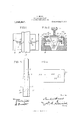
lvly invention will be described in detail hereinafter and illustrated in the accompanying drawings in which- Figure l is a top plan view of my improved rail clamp applied to a tie. F 2 is a vertical sectional view showing the rail clamped thereby. Fig. 3 is an edge view of the two clamping members, and Fig. 4 is a plan view of one of the clamp operating blocks.
Referring now to the drawings 1 repre sents a plate which is secured in a metallic or concrete tie 2 in any desired manner and which has at each end the downwardly extending end walls 3 and 4. Mounted in the side walls 5 of the said plate is a bolt or rod 6 upon which are mounted the rail clamps 7 and S. The clamp 7 has its lower end bifurcated and the arms 9 and 10 are provided with oppositely arranged openings 11 through which the bolt or rod 6 passes. The lower end of the rail clamp S is reduced in thickness so that it will freely pass between the two arms 9 and 10 of the bifurcated end of the clamp 7 and is provided with an opening 12 through which the bolt or rod 6 passes.
The upper ends of the rail clamps are provided with inwardly extending lateral ends 13 and 14 which extend through an elongated opening 15 in the plate 2 and are adapted to clamp the upper face of the base 16 of the rail 17. The formation of the lower ends of the rail clamps allows the two laterally turned upper ends to engage the base of the rail exactly opposite each other.
The rail as shown in F 2 rests upon the plate 2 across the center of the opening 15 and the rail clamps extend through said opening ,on each side of the base of the rail. In order ,to firmly hold the rail clamp in the position shown in Fig. 2, I provide the upper face of the plate 2 with small openings 11-8 and 19 adjacent the ends of the elongated opening 15. Below said plate are arranged the clamping blocks 20 and 21 which are of the shape shown in Figs. 2 and it. The said blocks are of a width equal to the thickness of the rail clamp and have their inner edges beveled as indicated at 22 which are adapted to engage the outer edges of the two rail clamps 7 and 8. The outer edges of the blocks are straight as indivertical end walls 3 and 4 of the plate 1. The blocks are provided with vertically disposed screw-threaded openings 2% and 25 into which are screwed the screw- bolts 26 and 27. These bolts pass downwardly through the openings 18 and 19 and have their heads bearing against the upper face of the plate.
The blocks having the beveled faces 22 hearing against the rail clamps it will be seen that by screwing the bolts in, the blocks are drawn upwardly and their bevel-ed edges forced against the clamps which clamp the base of the rail; the end walls of the plate preventing the outward movement of blocks. The unscrewing of the bolts allows the blocks to drop by force of gravity and then the rail clamps by force of gravity will move outwardly and release the rail.
This structure of a rail clamp allows of the tightening of the same at any time without disturbing the rail and also allows for the proper adjustment of the rails to or from each other to obtain the proper gage. This can be accomplished by forcing one block down on one side and drawing the other block up on the other side.
Having thus described my invention, what I claim is 1. A device of the character described, comprising a housing having a slot in its upper end, pivoted rail clamps mounted in the lower end of the housing and extending through said slot, blocks within the housing for operating said clamps, and screw bolts passing through the upper end of the hous- ,cated at 23 and are adaptedto engage the ing for raising and lowering said blocks, substantially as shown.
2. A. device of the character described, comprising a housing having a slot in its upper end, pivoted rail clamps mounted in the lower end of the housing and extending through the slot, blocks within the housing and having beveled ends engaging the outer edges of said clamps, and bolts pass ing through the upper end of the housing and screwed into said blocks, whereby the blocks are drawn upwardly for forcing the clamps inwardly.
A device of the character described, comprising a housing having a slot in its upper end, a horizontal bolt in said housing, rail clamps mounted on said bolt and extending through the slot, blocks within the housing and having vertical outer ends engaging the housing and beveled inner ends engaging the rail clamps, and screw-bolts passing loosely through the upper end of the housing and screwed into the blocks whereby the blocks are drawn upwardly for forcing the rail clamps inwardly.
4. A device of the character described,
comprising a housing having an elongated longitudinal slot in its upper end, a horizontal bolt in the lower end of the housing, a rail clamp having a bifurcated lower end, the arms of which have oppositely arranged openings through which the bolt passes, a second rail clamp having a reduced lower end mounted on the bolt between the arms of the bifurcated end of the first mentioned clamp, the upper ends of the clamps extending through the slot in the upper end of the housing, blocks within the housing and having vertical outer ends engaging the side walls of the housing and beveled inner ends engaging the rail clamps, and screw-bolts passing through openings in the upper end of the housing and screwed into the blocks whereby the blocks are drawn upwardly for forcing'the rail clamps inwardly. V
In testimony whereof I hereto aflix my signature in the presence of two witnesses.
FRANK MAAS. Witnesses:
O. L. Tomzrr'r, HENRY MEYER.
Copies of this patent may be obtained for five cents each, by addressing the Commissioner of Patents, Washington, D. C.
Priority Applications (1)
| Application Number | Priority Date | Filing Date | Title |
|---|---|---|---|
| US69256412A US1069447A (en) | 1912-04-23 | 1912-04-23 | Railway-rail clamp. |
Applications Claiming Priority (1)
| Application Number | Priority Date | Filing Date | Title |
|---|---|---|---|
| US69256412A US1069447A (en) | 1912-04-23 | 1912-04-23 | Railway-rail clamp. |
Publications (1)
| Publication Number | Publication Date |
|---|---|
| US1069447A true US1069447A (en) | 1913-08-05 |
Family
ID=3137684
Family Applications (1)
| Application Number | Title | Priority Date | Filing Date |
|---|---|---|---|
| US69256412A Expired - Lifetime US1069447A (en) | 1912-04-23 | 1912-04-23 | Railway-rail clamp. |
Country Status (1)
| Country | Link |
|---|---|
| US (1) | US1069447A (en) |
Cited By (1)
| Publication number | Priority date | Publication date | Assignee | Title |
|---|---|---|---|---|
| US4919330A (en) * | 1989-03-03 | 1990-04-24 | Winger James W | Quick release railroad highway crossing |
-
1912
- 1912-04-23 US US69256412A patent/US1069447A/en not_active Expired - Lifetime
Cited By (1)
| Publication number | Priority date | Publication date | Assignee | Title |
|---|---|---|---|---|
| US4919330A (en) * | 1989-03-03 | 1990-04-24 | Winger James W | Quick release railroad highway crossing |
Similar Documents
| Publication | Publication Date | Title |
|---|---|---|
| US1069447A (en) | Railway-rail clamp. | |
| US1081702A (en) | Concrete railway-tie. | |
| US1136288A (en) | Railway-tie and clamp. | |
| US1181563A (en) | Rail-clamp. | |
| US1009932A (en) | Metallic railroad-tie. | |
| US1113825A (en) | Tie for railway-rails. | |
| US834536A (en) | Railway-tie. | |
| US857479A (en) | Railway-track clamp. | |
| US773622A (en) | Railway-tie. | |
| US1196339A (en) | Rail clamping and fastening device. | |
| US691037A (en) | Rail-joint. | |
| US1012942A (en) | Tie. | |
| US1097373A (en) | Railway-tie and clamp. | |
| US990615A (en) | Railway-rail tie and fastener. | |
| US1029458A (en) | Rail-fastening means for railway-ties. | |
| US1082042A (en) | Combined rail brace and splice. | |
| US708347A (en) | Railroad-bed. | |
| US1191025A (en) | Rail-fastener. | |
| US656883A (en) | Rail-joint. | |
| US813584A (en) | Iron railroad-tie. | |
| US1084501A (en) | Cross-tie. | |
| US797085A (en) | Railway-rail stay. | |
| US714559A (en) | Railway-tie. | |
| US1029964A (en) | Rail-clamp. | |
| US860010A (en) | Guard-rail clamp. |