US1069062A - Pneumatic-tube system. - Google Patents
Pneumatic-tube system. Download PDFInfo
- Publication number
- US1069062A US1069062A US1912698553A US1069062A US 1069062 A US1069062 A US 1069062A US 1912698553 A US1912698553 A US 1912698553A US 1069062 A US1069062 A US 1069062A
- Authority
- US
- United States
- Prior art keywords
- tube
- closure
- cartridge
- door
- pneumatic
- Prior art date
- Legal status (The legal status is an assumption and is not a legal conclusion. Google has not performed a legal analysis and makes no representation as to the accuracy of the status listed.)
- Expired - Lifetime
Links
- 238000010276 construction Methods 0.000 description 5
- 238000012856 packing Methods 0.000 description 3
- 208000027418 Wounds and injury Diseases 0.000 description 2
- 230000006378 damage Effects 0.000 description 1
- 230000000994 depressogenic effect Effects 0.000 description 1
- 230000000694 effects Effects 0.000 description 1
- 208000014674 injury Diseases 0.000 description 1
- 238000003780 insertion Methods 0.000 description 1
- 230000037431 insertion Effects 0.000 description 1
- 239000010985 leather Substances 0.000 description 1
- 239000000463 material Substances 0.000 description 1
- 230000004048 modification Effects 0.000 description 1
- 238000012986 modification Methods 0.000 description 1
Images

Classifications
-
- B—PERFORMING OPERATIONS; TRANSPORTING
- B65—CONVEYING; PACKING; STORING; HANDLING THIN OR FILAMENTARY MATERIAL
- B65G—TRANSPORT OR STORAGE DEVICES, e.g. CONVEYORS FOR LOADING OR TIPPING, SHOP CONVEYOR SYSTEMS OR PNEUMATIC TUBE CONVEYORS
- B65G51/00—Conveying articles through pipes or tubes by fluid flow or pressure; Conveying articles over a flat surface, e.g. the base of a trough, by jets located in the surface
- B65G51/02—Directly conveying the articles, e.g. slips, sheets, stockings, containers or workpieces, by flowing gases
-
- Y—GENERAL TAGGING OF NEW TECHNOLOGICAL DEVELOPMENTS; GENERAL TAGGING OF CROSS-SECTIONAL TECHNOLOGIES SPANNING OVER SEVERAL SECTIONS OF THE IPC; TECHNICAL SUBJECTS COVERED BY FORMER USPC CROSS-REFERENCE ART COLLECTIONS [XRACs] AND DIGESTS
- Y10—TECHNICAL SUBJECTS COVERED BY FORMER USPC
- Y10T—TECHNICAL SUBJECTS COVERED BY FORMER US CLASSIFICATION
- Y10T137/00—Fluid handling
- Y10T137/8593—Systems
- Y10T137/87917—Flow path with serial valves and/or closures
- Y10T137/87981—Common actuator
Definitions
- My invention relates to improvements in pneumatic tube systems and has for its object the provision of a system of this character having improved means for introducing cartridges thereto.
- a further object of the invention consists in providing an improved cartridge for use in such systems.
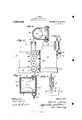
- Figure 1 is a partial vertical section of a portion of a pneumatic tube system embodying my invention, Fig. 2, a bottom plan view of trigger mechanism employed in the construction, Fig. 3, a section taken on line m-w of Fig. 2, Fig. 4,a side elevation, partially in section, of an improved cartridge adapted to be employed in conjunction with the system, Fig.5, a side elevation of the entry casing for a branch tube of the system, Fig. 6, a section taken on substantially line y-y of Fig. 5, Fig. 7 an elevation at right angles to Fig. 5, Fig. 8, a section taken on substantially line zz of Fig. 7, and Fig. 9, a section corresponding with Fig. 6 but showing a modified form of construction.
- the preferred form of construction as illustrated in the drawings comprises a main tube 1 of a pneumatic tube system and a branch tube 2' leading thereto, said branch tube being designed to be located at a station of the system.
- An entry casing 3 is secured about the lower end of branch tube 2 and a swinging closure 4 is secured to a shaft 5 mounted in casing 1.
- Closure 4 is provided with a leather packing plate 6 adapted to seat upon a valve seat 7 in casing 3 at the entry to tube 2, said-closure being thus adapted to close the lower end of tube 2 to prevent entry of air thereto.
- At one end shaft 5 is extended beyond casing 3 and a cylindrical plate or collar 8 is secured to said shaft.
- Plate 8 is provided with a notch 9 adapted to receive the end of a spring held catch or bolt 10, as indicated, said notch 9 being so positioned as to engage catch 10 when closure 4 is swung to open position, as indicated in dotted lines in Fig. 1.
- a coil spring 11 is secured to shaft 5 and arranged to hold closure 4 normally in closed position and to be wound up when said closure is swung to open position.
- a wire 12 is connected with the end of catch 10 and extends upwardly through a guide tube 13 and is secured at its upper end to a trigger 14 pivotally mounted on tube 2 adjacent its juncture with main tube 1.
- a slot 15 is provided in the adjacent wall of tube 2 to permit trigger 14 to swing into and out of tube 2, as shown in Fig. 1.
- casing 3 The lower end of casing 3 is provided with an inwardly swinging door 16 which is fixed to a shaft 17 mounted in casing 3. At one end shaft 17 is extended and carries a pinion 18 fixed thereto. Pinion 18 is connected by means of a chain of gears 19 with a similar pinion 20 secured to the corresponding end of shaft 5, the arrangement being such that when door 16 is swung inwardly and upwardly, closure 4 is swung outwardly and downwardly to assume the relative positions indicated by dotted lines in Fig. 1 By this arrangement it will be observed that a cartridge may be readily inserted upwardly into casing 3 and that such insertion will automatically open closure 4 to permit said cartridge to pass into the lower end of branch tube 2.
- a partial vacuum is always maintained in main tube 1 as is usual in such systems, so that when a cartridge is thus inserted in casing 3, it will be drawn by such vacuum upwardly through branch tube 2.
- catch 10 engages the notch 9 in plate 8 and locks said closure and door 16 in open position, thus permitting entry of air to the lower end of "tube 2 and causing the cartridges to ascend in tube 2 under the influence of the vacuum in tube 1 as will be readily understood by those skilled in the art.
- trigger 1 1 is struck thereby and swung outwardly, thus drawing wire 12 upwardly and releasing catch 10 from notch 9, whereupon closure 4 and door 16 are closed automatically by spring 11, as will be readily understood, thus preventing entry of further air to main tube 1 and impairing the partial vacuum therein.
- the cartridge employed in conjunction with the system above described is illustrated in Fig. 4 and comprises a suitable metallic receptacle 21 having felt pads 22 arranged at eachend and adapted to snugly ;;fit within tubes 1 and 2, so as to cause propulsion of said cartridge under the partial vacuum in the system, as will be readily understood.
- These pads are secured in position by means of guard plates 23 which are ,;made of slightly less area than said pads and are secured in position by means of screws 24 threaded in the ends of receptacle 21.
- Fig. 9 I have illustrated a modified form of construction that can be used in conjunction with a system having cylindrical tubes, as distinguished from square tubes illustrated in the other views.
- 40 that before described.
- a pneumatic tube system the combination of a main tube; a branch tube leading thereto; a closure for the end of said branch tube; and means located at the junction between said branch and main tubes and adapted to be operated automatically by a cartridge passing through said branch tube and arranged to close said closure, substantially as described.
- a pneumatic tube system the combination of a main tube; a branch tube leading thereto; a spring held closure for the end of said branch tube; means for locking said closure in open position; and trigger mechanism located at the junction between said branch and main tubes and adapted to be operated automatically by a cartridge passing through said branch tube and arranged to release said closure, substantially as described.
- a pneumatic tube system the combination of a main tube; a branch tube leading thereto; a closure for the end of said branch tube; means located at the junction between said branch and main tubes and adapted to be operated automatically by a cartridge passing through'said branch tube and arranged to close said closure; a cartridge adapted to operate in said tubes; a pad at one end of said cartridge and fitting said tubes; and-a guard plate covering said pad, substantially as described.
- a pneumatic tube system the combination of a main tube; a branch tube leading thereto; an outwardly opening spring held door normally closing the end of said branch tube; a catch arranged to hold said door in open position; trigger mechanism in said branch tube adapted to be operated by,
- a pneumatic tube system the combination of a main tube; a branch tube leading thereto; an outwardly opening spring held door normally closing the end of said branch tube; a catch arranged to hold sa1d door in open position; trlgger mechanism 111 sa1d branch tube adapted to be operated by the passage of a cartrldge therethrough and arranged to release sa1d catch; an entry casing surrounding sa1d closure; an in? wardly swinging door giving access to said casing; an operative connection between said door and said closure arranged to open said closure upon opening-of said door; a cartridge adapted to operate in said tubes;
Landscapes
- Physics & Mathematics (AREA)
- Engineering & Computer Science (AREA)
- Fluid Mechanics (AREA)
- Mechanical Engineering (AREA)
- Measurement Of The Respiration, Hearing Ability, Form, And Blood Characteristics Of Living Organisms (AREA)
Description
A. HERZ.
PNEUMATIC TUBE SYSTEM.
APPLIGATION FILED MAY 20, 1912.
' Patented July 29, 1913.
2 SHBETSSHEET 1.
COLUMBIA PLANOGRAPH ed, WASHINGTON. D. C
A. HERZ. PNEUMATIC TUBE SYSTEM. APPLICATION FILED MAY 20, 1912.
Patented July 29, 1913.
2 sums-sum 2.
111: III. III'III IT. 7
, IIIIIIIIIIIIIIIIL'QIIIiQ/I IIIIII/IIIIIIIIIIIIIIIIIZ/IIZ llilflluflii coLummA I'LANOGRAPH c0 WASHINGTON. n, c.
ALFRED HERZ, OF CHICAGO, ILLINOIS.
PNEUMATIC-TUBE SYSTEM.
Specification of Letters Patent.
Patented July 29, 1913.
Application filed May 20, 1912. Serial No. 698,553.
To all whom it may concern:
Be it known that I, ALFRED HnRz, a citizen of the United States, and a resident of the city of Chicago, county of Cook, and State of Illinois, have invented certain new and useful Improvements in Pneumatic-Tube Systems, of which the following is a specification.
My invention relates to improvements in pneumatic tube systems and has for its object the provision of a system of this character having improved means for introducing cartridges thereto.
A further object of the invention consists in providing an improved cartridge for use in such systems.
The invention consists in the combinations and arrangements of parts'hereinafter described and claimed.
The invention will be more readily understood byreference to the accompanying drawings forming a part of this specification, and in which,
Figure 1 is a partial vertical section of a portion of a pneumatic tube system embodying my invention, Fig. 2, a bottom plan view of trigger mechanism employed in the construction, Fig. 3, a section taken on line m-w of Fig. 2, Fig. 4,a side elevation, partially in section, of an improved cartridge adapted to be employed in conjunction with the system, Fig.5, a side elevation of the entry casing for a branch tube of the system, Fig. 6, a section taken on substantially line y-y of Fig. 5, Fig. 7 an elevation at right angles to Fig. 5, Fig. 8, a section taken on substantially line zz of Fig. 7, and Fig. 9, a section corresponding with Fig. 6 but showing a modified form of construction.
The preferred form of construction as illustrated in the drawings comprises a main tube 1 of a pneumatic tube system and a branch tube 2' leading thereto, said branch tube being designed to be located at a station of the system. An entry casing 3 is secured about the lower end of branch tube 2 and a swinging closure 4 is secured to a shaft 5 mounted in casing 1. Closure 4 is provided with a leather packing plate 6 adapted to seat upon a valve seat 7 in casing 3 at the entry to tube 2, said-closure being thus adapted to close the lower end of tube 2 to prevent entry of air thereto. At one end shaft 5 is extended beyond casing 3 and a cylindrical plate or collar 8 is secured to said shaft. Plate 8 is provided with a notch 9 adapted to receive the end of a spring held catch or bolt 10, as indicated, said notch 9 being so positioned as to engage catch 10 when closure 4 is swung to open position, as indicated in dotted lines in Fig. 1. A coil spring 11 is secured to shaft 5 and arranged to hold closure 4 normally in closed position and to be wound up when said closure is swung to open position. A wire 12 is connected with the end of catch 10 and extends upwardly through a guide tube 13 and is secured at its upper end to a trigger 14 pivotally mounted on tube 2 adjacent its juncture with main tube 1. A slot 15 is provided in the adjacent wall of tube 2 to permit trigger 14 to swing into and out of tube 2, as shown in Fig. 1. By this arrangement it will be observed that when closure 4 is open a cartridge may be inserted in the lower end of tube 2 and the passage of said cartridge through tube 2 into tube 1 will operate trigger 14 to withdraw catch 10 and release closure 4 to permit closing of the same under the influence of spring 11.
The lower end of casing 3 is provided with an inwardly swinging door 16 which is fixed to a shaft 17 mounted in casing 3. At one end shaft 17 is extended and carries a pinion 18 fixed thereto. Pinion 18 is connected by means of a chain of gears 19 with a similar pinion 20 secured to the corresponding end of shaft 5, the arrangement being such that when door 16 is swung inwardly and upwardly, closure 4 is swung outwardly and downwardly to assume the relative positions indicated by dotted lines in Fig. 1 By this arrangement it will be observed that a cartridge may be readily inserted upwardly into casing 3 and that such insertion will automatically open closure 4 to permit said cartridge to pass into the lower end of branch tube 2. A partial vacuum is always maintained in main tube 1 as is usual in such systems, so that when a cartridge is thus inserted in casing 3, it will be drawn by such vacuum upwardly through branch tube 2. When closure 4 is thus swung to open position, catch 10 engages the notch 9 in plate 8 and locks said closure and door 16 in open position, thus permitting entry of air to the lower end of "tube 2 and causing the cartridges to ascend in tube 2 under the influence of the vacuum in tube 1 as will be readily understood by those skilled in the art. As the cartridge passes through tube 2 into the tube 1, trigger 1 1 is struck thereby and swung outwardly, thus drawing wire 12 upwardly and releasing catch 10 from notch 9, whereupon closure 4 and door 16 are closed automatically by spring 11, as will be readily understood, thus preventing entry of further air to main tube 1 and impairing the partial vacuum therein.
The cartridge employed in conjunction with the system above described, is illustrated in Fig. 4 and comprises a suitable metallic receptacle 21 having felt pads 22 arranged at eachend and adapted to snugly ;;fit within tubes 1 and 2, so as to cause propulsion of said cartridge under the partial vacuum in the system, as will be readily understood. These pads are secured in position by means of guard plates 23 which are ,;made of slightly less area than said pads and are secured in position by means of screws 24 threaded in the ends of receptacle 21. By this arrangement it will be observed that pads 22 will constitute a good packing vfor the cartridge in the tubes of the system and that trigger 14 will be struck by the edge of the forward guard plate 23 and be depressed thereby, thus preventing injury or material wear on the corresponding felt packing 22.
In Fig. 9 I have illustrated a modified form of construction that can be used in conjunction with a system having cylindrical tubes, as distinguished from square tubes illustrated in the other views. Here 40 .;that before described.
While I have illustrated and described the preferred forms of construction for carrying my invention into effect, these are capable of variation and modification without departing from the spirit of the invention.
' claim as new and desire to secure by Letters Patent is:
1. In a pneumatic tube system the combination of a main tube; a branch tube leading thereto; a closure for the end of said branch tube; and means located at the junction between said branch and main tubes and adapted to be operated automatically by a cartridge passing through said branch tube and arranged to close said closure, substantially as described.
2. In a pneumatic tube system the combination of a main tube; a branch tube leading thereto; a spring held closure for the end of said branch tube; means for locking said closure in open position; and trigger mechanism located at the junction between said branch and main tubes and adapted to be operated automatically by a cartridge passing through said branch tube and arranged to release said closure, substantially as described.
3. In a pneumatic tube system the combination of a main tube; a branch tube leading thereto; a closure for the end of said branch tube; means located at the junction between said branch and main tubes and adapted to be operated automatically by a cartridge passing through'said branch tube and arranged to close said closure; a cartridge adapted to operate in said tubes; a pad at one end of said cartridge and fitting said tubes; and-a guard plate covering said pad, substantially as described.
4:. In a pneumatic tube system the combination of a main tube; a branch tube leading thereto; an outwardly opening spring held door normally closing the end of said branch tube; a catch arranged to hold said door in open position; trigger mechanism in said branch tube adapted to be operated by,
the passage of a cartridge therethrough and arranged to release said catch; an entry casing surrounding said closure; an inwardly swinging door giving access'to said casing; and an operative connection between said door and said closure arranged to open said closure upon opening of said door, substantially as described.
5. In a pneumatic tube system the combination of a main tube; a branch tube leading thereto; an outwardly opening spring held door normally closing the end of said branch tube; a catch arranged to hold sa1d door in open position; trlgger mechanism 111 sa1d branch tube adapted to be operated by the passage of a cartrldge therethrough and arranged to release sa1d catch; an entry casing surrounding sa1d closure; an in? wardly swinging door giving access to said casing; an operative connection between said door and said closure arranged to open said closure upon opening-of said door; a cartridge adapted to operate in said tubes;
a pad on one end of said cartridge and fitopening closure therefor; an entry casing surrounding said closure; an inwardly opening door for said casing; and an operative connection between said door and closure whereby opening of said door automatically opens said closure, substantially as described.
In testimony whereof I have signed my name to this specification in the presence of two subscribing witnesses.
ALFRED HERZ.
Witnesses:
JosHUA R. H. Po rrs, BRAYTON G. RICHARDS.
Copies of this patent may be obtained for five cents each, by addressing the Commissioner of Patents, Washington, D. G.
Priority Applications (1)
| Application Number | Priority Date | Filing Date | Title |
|---|---|---|---|
| US1912698553 US1069062A (en) | 1912-05-20 | 1912-05-20 | Pneumatic-tube system. |
Applications Claiming Priority (1)
| Application Number | Priority Date | Filing Date | Title |
|---|---|---|---|
| US1912698553 US1069062A (en) | 1912-05-20 | 1912-05-20 | Pneumatic-tube system. |
Publications (1)
| Publication Number | Publication Date |
|---|---|
| US1069062A true US1069062A (en) | 1913-07-29 |
Family
ID=3137300
Family Applications (1)
| Application Number | Title | Priority Date | Filing Date |
|---|---|---|---|
| US1912698553 Expired - Lifetime US1069062A (en) | 1912-05-20 | 1912-05-20 | Pneumatic-tube system. |
Country Status (1)
| Country | Link |
|---|---|
| US (1) | US1069062A (en) |
Cited By (2)
| Publication number | Priority date | Publication date | Assignee | Title |
|---|---|---|---|---|
| DE1054921B (en) * | 1956-07-11 | 1959-04-09 | Siemens Ag | Air damper for pneumatic tube systems |
| US3294342A (en) * | 1965-11-05 | 1966-12-27 | Tv Bank Equipment Corp | Service facilities and equipment |
-
1912
- 1912-05-20 US US1912698553 patent/US1069062A/en not_active Expired - Lifetime
Cited By (2)
| Publication number | Priority date | Publication date | Assignee | Title |
|---|---|---|---|---|
| DE1054921B (en) * | 1956-07-11 | 1959-04-09 | Siemens Ag | Air damper for pneumatic tube systems |
| US3294342A (en) * | 1965-11-05 | 1966-12-27 | Tv Bank Equipment Corp | Service facilities and equipment |
Similar Documents
| Publication | Publication Date | Title |
|---|---|---|
| US242459A (en) | leayoraft | |
| US1134556A (en) | Water-closet tank. | |
| US462658A (en) | Franz august baier | |
| US1024617A (en) | Planograph co | |
| US1108018A (en) | Match-box. | |
| US414409A (en) | Barrel-cover | |
| US833920A (en) | Chalk-line holder. | |
| US986383A (en) | Lamp-cord adjuster. | |
| US1038455A (en) | Valve. | |
| US546684A (en) | Charles s | |
| US1038355A (en) | Detonator-magazine. | |
| US765760A (en) | Floor-thimble. | |
| US795636A (en) | Milk-can. | |
| US1089936A (en) | Fastener for pocket-lighters. | |
| US457809A (en) | Seat and seat cover for water closets | |
| US473360A (en) | Commode | |
| US295432A (en) | August schilling | |
| US985339A (en) | Envelop. | |
| US997261A (en) | Cigar-tip cutter. | |
| US353645A (en) | Geoegb w | |
| US113360A (en) | Improvement in match-safes | |
| US1087520A (en) | Receptacle-closure. | |
| US923816A (en) | Mail-receptacle. | |
| US1082867A (en) | Device for opening tubular carriers. | |
| US991945A (en) | Gun-shell attachment. |