US10668584B2 - Component mounting method - Google Patents
Component mounting method Download PDFInfo
- Publication number
- US10668584B2 US10668584B2 US15/695,276 US201715695276A US10668584B2 US 10668584 B2 US10668584 B2 US 10668584B2 US 201715695276 A US201715695276 A US 201715695276A US 10668584 B2 US10668584 B2 US 10668584B2
- Authority
- US
- United States
- Prior art keywords
- carrier
- workpiece holding
- holding body
- workpieces
- lifting
- Prior art date
- Legal status (The legal status is an assumption and is not a legal conclusion. Google has not performed a legal analysis and makes no representation as to the accuracy of the status listed.)
- Active, expires
Links
- 238000000034 method Methods 0.000 title claims description 8
- 230000036544 posture Effects 0.000 claims abstract description 54
- 230000032258 transport Effects 0.000 claims description 45
- 238000010586 diagram Methods 0.000 description 28
- 230000005540 biological transmission Effects 0.000 description 9
- 238000003384 imaging method Methods 0.000 description 2
- 238000004519 manufacturing process Methods 0.000 description 2
- 238000000926 separation method Methods 0.000 description 1
- 239000000758 substrate Substances 0.000 description 1
- 238000011144 upstream manufacturing Methods 0.000 description 1
- 230000000007 visual effect Effects 0.000 description 1
Images


Classifications
-
- H—ELECTRICITY
- H05—ELECTRIC TECHNIQUES NOT OTHERWISE PROVIDED FOR
- H05K—PRINTED CIRCUITS; CASINGS OR CONSTRUCTIONAL DETAILS OF ELECTRIC APPARATUS; MANUFACTURE OF ASSEMBLAGES OF ELECTRICAL COMPONENTS
- H05K13/00—Apparatus or processes specially adapted for manufacturing or adjusting assemblages of electric components
- H05K13/04—Mounting of components, e.g. of leadless components
-
- B—PERFORMING OPERATIONS; TRANSPORTING
- B23—MACHINE TOOLS; METAL-WORKING NOT OTHERWISE PROVIDED FOR
- B23P—METAL-WORKING NOT OTHERWISE PROVIDED FOR; COMBINED OPERATIONS; UNIVERSAL MACHINE TOOLS
- B23P21/00—Machines for assembling a multiplicity of different parts to compose units, with or without preceding or subsequent working of such parts, e.g. with programme control
-
- B—PERFORMING OPERATIONS; TRANSPORTING
- B23—MACHINE TOOLS; METAL-WORKING NOT OTHERWISE PROVIDED FOR
- B23P—METAL-WORKING NOT OTHERWISE PROVIDED FOR; COMBINED OPERATIONS; UNIVERSAL MACHINE TOOLS
- B23P19/00—Machines for simply fitting together or separating metal parts or objects, or metal and non-metal parts, whether or not involving some deformation; Tools or devices therefor so far as not provided for in other classes
- B23P19/001—Article feeders for assembling machines
- B23P19/007—Picking-up and placing mechanisms
-
- Y—GENERAL TAGGING OF NEW TECHNOLOGICAL DEVELOPMENTS; GENERAL TAGGING OF CROSS-SECTIONAL TECHNOLOGIES SPANNING OVER SEVERAL SECTIONS OF THE IPC; TECHNICAL SUBJECTS COVERED BY FORMER USPC CROSS-REFERENCE ART COLLECTIONS [XRACs] AND DIGESTS
- Y10—TECHNICAL SUBJECTS COVERED BY FORMER USPC
- Y10T—TECHNICAL SUBJECTS COVERED BY FORMER US CLASSIFICATION
- Y10T29/00—Metal working
- Y10T29/49—Method of mechanical manufacture
- Y10T29/49002—Electrical device making
- Y10T29/49117—Conductor or circuit manufacturing
- Y10T29/49124—On flat or curved insulated base, e.g., printed circuit, etc.
- Y10T29/4913—Assembling to base an electrical component, e.g., capacitor, etc.
- Y10T29/49133—Assembling to base an electrical component, e.g., capacitor, etc. with component orienting
Definitions
- the present disclosure relates to a component mounter which places components on a workpiece.
- a three-dimensionally shaped board which is referred to as a three-dimensional board or the like is known, and a component mounter which places components on a workpiece using such a three-dimensionally shaped board as the workpiece is known (for example, PTL 1 described below).
- a component mounter which places components on a workpiece using such a three-dimensionally shaped board as the workpiece is known (for example, PTL 1 described below).
- the posture of the workpiece is freely changed by a posture adjustment mechanism so that the surface of the component placing part which is set on the workpiece is caused to face upward, and then the component is placed on the component placing part by a placing head.
- a component mounter of the disclosure includes a workpiece holding body which holds, lined up in a row, a plurality of workpieces on which components are to be placed, a carrier onto which the workpiece holding body is placed, a transport conveyor which transports the carrier onto which the workpiece holding body is placed, a chuck portion which chucks the workpiece holding body which is on the carrier which is transported to a predetermined position using the transport conveyor, a lifting-lowering mechanism which separates the workpiece holding body from the carrier by performing an operation of lifting and lowering the chuck portion which chucks the workpiece holding body with respect to the carrier together with an operation of moving the carrier in the transport direction using the transport conveyor, a rotation mechanism which rotates the chuck portion which chucks the workpiece holding body which is separated from the carrier to adjust postures of the plurality of workpieces which are held in workpiece holding body, and a placing head which places the components on each of the plurality of workpieces which are subjected to posture adjustment by the rotation mechanism.
- a component mounting method of the disclosure for a component mounter including: a workpiece holding body which aligns and holds a plurality of workpieces on which components are to be placed; a carrier onto which the workpiece holding body is placed; a transport conveyor which transports the carrier onto which the workpiece holding body is placed; a chuck portion which chucks the workpiece holding body which is on the carrier which is transported to a predetermined position using the transport conveyor; and a placing head which places the components on each of the plurality of workpieces, the method including: separating the workpiece holding body from the carrier by performing an operation of lifting and lowering the chuck portion which chucks the workpiece holding body with respect to the carrier, and moving the carrier in the transport direction using the transport conveyor; rotating the chuck portion to adjust postures of the plurality of workpieces which are held in workpiece holding body; and placing the components on each of the plurality of workpieces which are subjected to posture adjustment.
- FIG. 1 is a perspective diagram of a component mounter of an exemplary embodiment of the disclosure
- FIGS. 2A and 2B are perspective diagrams illustrating a workpiece holding body with which the component mounter is provided together with workpieces in an exemplary embodiment of the disclosure
- FIGS. 3A and 3B are perspective diagrams illustrating the workpiece holding body with which the component mounter is provided together with a carrier in an exemplary embodiment of the disclosure
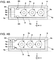
- FIGS. 4A and 4B are plan views illustrating the workpiece holding body with which the component mounter is provided together with the carrier in an exemplary embodiment of the disclosure
- FIG. 5 is a perspective diagram of a posture adjustment mechanism with which the component mounter is provided in an exemplary embodiment of the disclosure
- FIG. 6 is an exploded perspective diagram of the posture adjustment mechanism with which the component mounter is provided in an exemplary embodiment of the disclosure
- FIG. 7 is a block diagram illustrating a control system of the component mounter in an exemplary embodiment of the disclosure.
- FIGS. 8A and 8B are respectively a perspective diagram and a side surface diagram illustrating the posture adjustment mechanism with which the component mounter is provided together with a transport conveyor in an exemplary embodiment of the disclosure;
- FIGS. 9A and 9B are respectively a perspective diagram and a side surface diagram illustrating the posture adjustment mechanism with which the component mounter is provided together with a transport conveyor in an exemplary embodiment of the disclosure;
- FIGS. 10A and 10B are respectively a perspective diagram and a side surface diagram illustrating the posture adjustment mechanism with which the component mounter is provided together with a transport conveyor in an exemplary embodiment of the disclosure;
- FIGS. 11A and 11B are respectively a perspective diagram and a side surface diagram illustrating the posture adjustment mechanism with which the component mounter is provided together with a transport conveyor in an exemplary embodiment of the disclosure;
- FIGS. 12A and 12B are respectively a perspective diagram and a side surface diagram illustrating the posture adjustment mechanism with which the component mounter is provided together with a transport conveyor in an exemplary embodiment of the disclosure;
- FIGS. 13A and 13B are respectively a perspective diagram and a side surface diagram illustrating the posture adjustment mechanism with which the component mounter is provided together with a transport conveyor in an exemplary embodiment of the disclosure;
- FIGS. 14A and 14B are respectively a perspective diagram and a side surface diagram illustrating the posture adjustment mechanism with which the component mounter is provided together with a transport conveyor in an exemplary embodiment of the disclosure;
- FIGS. 15A and 15B are respectively a perspective diagram and a side surface diagram illustrating the posture adjustment mechanism with which the component mounter is provided together with a transport conveyor in an exemplary embodiment of the disclosure;
- FIGS. 16A and 16B are respectively a perspective diagram and a side surface diagram illustrating the posture adjustment mechanism with which the component mounter is provided together with a transport conveyor in an exemplary embodiment of the disclosure;
- FIGS. 17A and 17B are respectively a perspective diagram and a side surface diagram illustrating the posture adjustment mechanism with which the component mounter is provided together with a transport conveyor in an exemplary embodiment of the disclosure;
- FIGS. 18A and 18B are respectively a perspective diagram and a side surface diagram illustrating the posture adjustment mechanism with which the component mounter is provided together with a transport conveyor in an exemplary embodiment of the disclosure.
- an object of the disclosure is to provide a component mounter capable of handling a plurality of workpieces collectively when performing the posture adjustment of the workpieces, and capable of improving productivity.
- FIG. 1 illustrates component mounter 1 in an embodiment of the disclosure.
- Component mounter 1 is a device which places components P on workpiece 2 as a three-dimensional substrate called a three-dimensional board or the like on workpiece 2 .
- a left-right direction of component mounter 1 as viewed from worker OP is used as an X-axis direction
- a front-back direction is used as a Y-axis direction
- An up-down direction is used as a Z-axis direction.
- workpiece holding body 3 which holds workpiece 2 , and carrier 4 on which workpiece holding body 3 is placed.
- workpiece holding body 3 is configured of a plate-shape member which extends in the left-right direction (the X-axis direction), and includes a plurality of (here, three) workpiece holding holes 3 H which are provided to line up in the left-right direction.
- workpieces 2 are fixed to workpiece holding body 3 using a plurality of screws N.
- workpiece holding body 3 is configured to hold a plurality of workpieces 2 in a row.
- hollowed-out portions 3 K are provided on the left end portion side of each of a pair of long side portions of workpiece holding bodies 3 , which face each other in the Y-axis direction.
- carrier 4 is formed in a rectangular frame shape which has three lateral side portions 4 x extending parallel to the X-axis direction and two vertical side portions 4 y extending parallel to the Y-axis direction, and includes two openings 4 K which extend in the X-axis direction and are lined up in the Y-axis direction.
- Overhanging pieces 4 a which overhang into opening 4 K are provided in each of the three lateral side portions 4 x which face each other in the Y-axis direction with openings 4 K interposed therebetween.
- Workpiece holding body 3 assumes a state of being placed on carrier 4 by positioning the short side portion (left short side portion 3 a ) of workpiece holding body 3 on the side at which the pair of hollowed-out portions 3 K are provided on the pair of overhanging pieces 4 a of carrier 4 , and positioning right short side portion 3 b of workpiece holding body 3 on vertical side portion 4 y of the right side of carrier 4 ( FIG. 4A ).
- workpiece holding body 3 passes through opening 4 K in the up-down direction in a horizontal posture ( FIG. 4B ).
- component mounter 1 is provided with transporter 12 , a plurality of part feeders 13 , component camera 14 , posture adjustment mechanism 15 , and component mounting mechanism 16 on table 11 .
- Transporter 12 uses the X-axis direction as the transport direction, and is provided with three transport conveyors 21 in the transport direction. Three conveyors 21 are carry-in conveyor 21 A, working conveyor 21 B, and carry-out conveyor 21 C from the upstream side (left side) in the transport direction.
- Each conveyor 21 supports, from below, a pair of end portions which face each other in the Y-axis direction of carrier 4 , and transports carrier 4 in the X-axis direction.
- Each part feeder 13 is configured of a tape feeder, for example, and is attached to table 11 in a freely detachable manner.
- Each part feeder 13 supplies components P to component supply port 13 K which is provided on the side that is close to transporter 12 .
- Component camera 14 is provided on table 11 between transporter 12 and part feeder 13 in a state in which the imaging visual field faces upward.
- Posture adjustment mechanism 15 is provided under working conveyor 21 B. As described later, posture adjustment mechanism 15 separates workpiece holding body 3 from carrier 4 which is transported to the working position by working conveyor 21 B, and then collectively adjusts the postures of the plurality of workpieces 2 which are held in workpiece holding body 3 .
- component mounting mechanism 16 includes placing head 31 and head moving mechanism 32 .
- Placing head 31 is provided with a plurality of suction nozzles 31 a which extend downward. Placing head 31 moves (lifts and lowers) each suction nozzle 31 a in the Z-axis direction and rotates each suction nozzle 31 a around the Z axis, introduces a vacuum pressure which is supplied from a vacuum source (not illustrated), and applies vacuum suction force to the bottom end of each suction nozzle 31 a.
- Head moving mechanism 32 is provided with fixed beam 32 a which extends in the Y-axis direction and movable beam 32 b which extends in the X-axis direction. Placing head 31 is moved in the X-axis direction along movable beam 32 b , and movable beam 32 b is moved in the Y-axis direction along fixed beam 32 a . Therefore, it is possible to move placing head 31 in a horizontal plane using head moving mechanism 32 .
- posture adjustment mechanism 15 is provided with fixed base 41 , lifting-lowering cylinder 42 , lifting-lowering base 43 , a plurality of guide rods 44 , two chuck portions 45 , rotation motor 46 , and belt transmission mechanism 47 .
- Fixed base 41 is configured of a flat plate member which extends in the horizontal plane, and is provided to be fixed to table 11 below working conveyor 21 B.
- Lifting-lowering cylinder 42 is attached to the bottom surface side of the central portion of fixed base 41 .
- Piston rod 42 R of lifting-lowering cylinder 42 penetrates fixed base 41 from below to extend upward.
- Lifting-lowering base 43 is attached to the top end of piston rod 42 R of lifting-lowering cylinder 42 .
- lifting-lowering base 43 includes horizontal portion 43 a which extends in the horizontal plane and right and left vertical portions 43 b which extend vertically upward from the left and right end portions of horizontal portion 43 a .
- the plurality of guide rods 44 extend downward from the four corners of the bottom surface of horizontal portion 43 a of lifting-lowering base 43 and extend downward through fixed base 41 .
- Each guide rod 44 slides freely in the Z-axis direction with respect to fixed base 41 .
- each chuck portion 45 includes bottom portion 45 a and left and right wall portions 45 b .
- Bottom portion 45 a has a shape extending in the X-axis direction, and the left and right wall portions 45 b extend upward from the left and right end portions, respectively, of bottom portion 45 a.
- rotation shaft 45 J is provided to extend in the X-axis direction.
- the right and left rotation shafts 45 J extend on the same axial line (the X axis) and extend through the left and right vertical portions 43 b , respectively, in the X-axis direction. Therefore, chuck portions 45 rotate freely around the axial line of the left-right pair of rotation shafts 45 J.
- rotation shaft 45 J of the left side extends leftward through wall portion 45 b of the left side of lifting-lowering base 43 .
- a plurality of (here, two) holding body supporters 45 c are provided to extend upward in an intermediate portion in the left-right direction of bottom portion 45 a of chuck portion 45 .
- a plurality of suction openings 45 h are provided on the top surface of each holding body supporter 45 c . It is possible to generate a vacuum suction force in the plurality of suction openings 45 h through chuck control mechanism 48 ( FIG. 5 ), and so it is possible to chuck (suction hold) workpiece holding body 3 , which holds the plurality of workpieces 2 , from below.
- each chuck portion 45 is configured to chuck two workpiece holding bodies 3 which hold a plurality of workpieces 2 which are lined up in a row in the X-axis direction.
- a configuration is adopted in which two (that is, a plurality of) chuck portions 45 are provided on lifting-lowering base 43 to line up in the horizontal direction (the Y-axis direction) which is orthogonal to the lining up direction (the X-axis direction) of the plurality of workpieces 2 which are held in workpiece holding body 3 which is chucked by chuck portion 45 .
- rotation motor 46 is attached to the bottom surface side of horizontal portion 43 a of lifting-lowering base 43 with drive shaft 46 S facing to the left.
- Drive shaft 46 S protrudes and extends to the left side of vertical portion 43 b of the left side of lifting-lowering base 43 .
- belt transmission mechanism 47 is provided with drive pulley 51 , two follower pulleys 52 , tension roller 53 , and transmission belt 54 .
- Drive pulley 51 is attached to drive shaft 46 S of rotation motor 46 .
- Two follower pulleys 52 are attached to corresponding two rotation shafts 45 J which protrude and extend leftward from vertical portion 43 b of the left side of lifting-lowering base 43 .
- Tension roller 53 is provided to protrude and extend leftward from the left surface side of vertical portion 43 b of the left side of lifting-lowering base 43 .
- Transmission belt 54 is wound around drive pulley 51 , two follower pulleys 52 , and tension roller 53 . A suitable degree of tension is applied to transmission belt 54 by tension roller 53 .
- rotation motor 46 When rotation motor 46 operates and drive pulley 51 is rotationally driven by drive shaft 46 S, the rotational motive force of drive pulley 51 is transmitted to two follower pulleys 52 by transmission belt 54 . Accordingly, two front and rear chuck portions 45 are rotated around the axial line (the X axis) of the corresponding rotation shaft 45 J through two rotation shafts 45 J which are connected to two follower pulleys 52 .
- rotation motor 46 , belt transmission mechanism 47 , and the like configure a rotation mechanism RS which rotates two chuck portions 45 around the axial lines which extend in the lining up direction (the X-axis direction) of the plurality of workpieces 2 which are held in workpiece holding body 3 ( FIG. 5 ).
- lifting-lowering base 43 which is attached to piston rod 42 R is lifted and lowered with respect to fixed base 41 in a state of being guided by the plurality of guide rods 44 .
- lifting-lowering cylinder 42 , lifting-lowering base 43 , and the like configure lifting-lowering mechanism LS which lifts and lowers two front and rear chuck portions 45 together with rotation mechanism RS ( FIG. 5 ).
- control device 60 of component mounter 1 controls transportation of carrier 4 by transport conveyor 21 (carry-in conveyor 21 A, working conveyor 21 B, and carry-out conveyor 21 C), supplying of components P by part feeder 13 , lifting, lowering, and rotation of each suction nozzle 31 a by placing head 31 , suction by each suction nozzle 31 a , moving of placing head 31 by head moving mechanism 32 , and imaging by component camera 14 .
- Control device 60 controls the lifting and lowering of lifting-lowering base 43 by lifting-lowering cylinder 42 , the rotation of two chuck portions 45 by rotation motor 46 , and the chucking of each chuck portion 45 by chuck control mechanism 48 .
- carrier 4 is supplied to carry-in transporter 21 A of transporter 12 in a state in which two workpiece holding bodies 3 , each of which holds a plurality of (here, three) workpieces 2 , are placed on carrier 4 ( FIG. 8A ). In this state, carrier 4 is not positioned above posture adjustment mechanism 15 ( FIG. 8B ).
- control device 60 operates carry-in conveyor 21 A to deliver carrier 4 to working conveyor 21 B.
- Work conveyor 21 B is operated and carrier 4 is positioned at a predetermined working position ( FIG. 9A ).
- carrier 4 is positioned at the working position, two workpiece holding bodies 3 which are placed on carrier 4 assume a state of being positioned above two chuck portions 45 ( FIG. 9B ).
- control device 60 lifts lifting-lowering base 43 using lifting-lowering cylinder 42 . Then it causes the top surfaces of each of the plurality of holding body supporters 45 c with which each chuck portion 45 is provided to come into contact with workpiece holding body 3 that is positioned thereabove from below.
- control device 60 controls chuck control mechanism 48 to generate a vacuum suction force in suction openings 45 h which are provided in each holding body supporter 45 c and to cause chuck portion 45 to chuck workpiece holding body 3 ( FIGS. 10A and 10B ).
- control device 60 lifts lifting-lowering base 43 using lifting-lowering cylinder 42 , lifts two workpiece holding bodies 3 using two chuck portions 45 , and causes two workpiece holding bodies 3 to separate from carrier 4 ( FIGS. 11A and 11B ).
- control device 60 operates working conveyor 21 B to move carrier 4 slightly in the X-axis direction ( FIGS. 12A and 12B ).
- the direction in which carrier 4 is moved using working conveyor 21 B is a direction (the direction from FIG. 4A to 4B ) in which each workpiece holding body 3 passes under opening 4 K of carrier 4 .
- control device 60 lowers lifting-lowering base 43 using lifting-lowering cylinder 42 , two workpiece holding bodies 3 which are chucked using two chuck portions 45 pass through opening 4 K of carrier 4 from above carrier 4 to under carrier 4 . All of the plurality of workpieces 2 which are held in two workpiece holding bodies 3 are positioned under carrier 4 ( FIGS. 13A and 13B ). Accordingly, two workpiece holding bodies 3 assume a state of being separated from carrier 4 .
- lifting-lowering mechanism LS separates carrier 4 from workpiece holding body 3 by performing an operation of lifting and lowering chuck portion 45 which chucks workpiece holding body 3 with respect to carrier 4 together with an operation of moving carrier 4 in the transport direction (the X-axis direction) using transport conveyor 21 (specifically, working conveyor 21 B).
- carrier 4 is configured in a frame shape including openings 4 K in inner portion of carrier 4 , and workpiece holding body 3 is separated from carrier 4 by being caused to pass under openings 4 K by being transported to the predetermined working position using transport conveyor 21 in a state of being placed on carrier 4 at a position at which workpiece holding body 3 does not fall from openings 4 K of carrier 4 , in other words, avoids openings 4 K of carrier 4 , and through the linked operation of the lifting and lowering of chuck portion 45 by lifting-lowering mechanism LS and the movement of carrier 4 in the transport direction (the X-axis direction) by transport conveyor 21 .
- control device 60 operates working conveyor 21 B to deliver carrier 4 to carry-out conveyor 21 C. Once carrier 4 is delivered to carry-out conveyor 21 C, carrier 4 waits above carry-out conveyor 21 C ( FIGS. 14A and 14B ).
- carrier 4 which is separated from workpiece holding body 3 is delivered from working conveyor 21 B to carry-out conveyor 21 C; however, carrier 4 may be delivered from working conveyor 21 B to carry-in conveyor 21 A.
- control device 60 lifts lifting-lowering base 43 using lifting-lowering cylinder 42 ( FIGS. 15A and 15B ).
- the postures of the plurality of workpieces 2 which are held by two workpiece holding bodies 3 are collectively adjusted by operating rotation motor 46 to rotationally drive drive pulley 51 using drive shaft 46 S, and causing two chuck portions 45 to rotate around the axial lines of rotation shafts 45 J at the same time, in the same direction, at the same angle through belt transmission mechanism 47 ( FIGS. 16A and 16B .
- chuck portion 45 is rotated such that the surface of component placing part 2 R faces upward (assumes a horizontal posture).
- Each workpiece 2 is attached to workpiece holding body 3 such that the surface of component placing part 2 R faces upward due to the turning operation of chuck portion 45 .
- Rotation mechanism RS including rotation motor 46 causes chuck portion 45 which chucks workpiece holding body 3 to rotate around the axial line (the X axis) extending in the lining up direction of the plurality of workpieces 2 which are held in workpiece holding body 3 , and the postures of the plurality of workpieces 2 which are held in workpiece holding body 3 which is separated from carrier 4 are collectively adjusted.
- (1) workpiece holding body 3 which holds the plurality of workpieces 2 lined up in a row in the X-axis direction is placed on carrier 4 and transported to a predetermined position (the working position) by transport conveyor 21 (2).
- Transported workpiece holding body 3 which is on carrier 4 is chucked by chuck portion 45 , and then, (3) chuck portion 45 is lifted and lowered with respect to carrier 4 using lifting-lowering mechanism LS and moves carrier 4 in the transport direction (the X-axis direction) using transport conveyor 21 .
- lifting-lowering mechanism LS lifting-lowering mechanism
- control device 60 After collectively adjusting the postures of the plurality of workpieces 2 , control device 60 lifts and lowers lifting-lowering base 43 using lifting-lowering cylinder 42 , and ensures that each component placing part 2 R of the plurality of workpieces 2 is matched with the placing height at which components P are placed by suction nozzles 31 a ( FIGS. 17A and 17B ).
- the plurality of workpieces 2 with adjusted postures are collectively positioned at a predetermined height (the placing height) using the lifting and lowering (that is, the lifting and lowering of chuck portions 45 ) operation of lifting-lowering base 43 by lifting-lowering mechanism LS.
- posture adjustment mechanism 15 with which component mounter 1 in the present exemplary embodiment is provided, the part at which it is possible to perform the posture adjustment in workpiece 2 is limited; however, since posture adjustment mechanism 15 is to be configured such that the surface of component placing part 2 R on which components P are to be placed faces a predetermined direction (for example, upward). Therefore, in a case in which component placing part 2 R is one location for one workpiece 2 , this is cost effective in manufacturing due to the simplification in the configuration of posture adjustment mechanism 15 .
- control device 60 operates part feeder 13 to supply components P to component supply port 13 K, and moves placing head 31 above part feeder 13 using head moving mechanism 32 . Components P are sucked by each of the plurality of suction nozzles 31 a with which placing head 31 is provided.
- control device 60 moves placing head 31 using head moving mechanism 32 , and ensures that the plurality of components P which are sucked by suction nozzle 31 a sequentially pass over component camera 14 .
- control device 60 moves placing head 31 above working conveyor 21 B using head moving mechanism 32 , and positions component P above component placing part 2 R of workpiece 2 which is subjected to posture adjustment by posture adjustment mechanism 15 ( FIGS. 18A and 18B ).
- control device 60 lowers suction nozzle 31 a and places component P on component placing part 2 R.
- the interval between the plurality of workpieces 2 which are held in workpiece holding body 3 is set to match the interval between the plurality of suction nozzles 31 a , and so it is possible to collectively (or alternatively, sequentially) place components P with respect to the plurality of workpieces 2 which are held in workpiece holding body 3 .
- Control device 60 causes placing head 31 to reciprocate between the upper position of working conveyor 21 B and part feeder 13 to place components P on all workpieces 2 which are subjected to posture adjustment by posture adjustment mechanism 15 .
- control device 60 operates posture adjustment mechanism 15 and transport conveyor 21 in the reverse order from that in the above-described procedure, and places two workpiece holding bodies 3 on carrier 4 which is positioned at the working position.
- control device 60 operates working conveyor 21 B to deliver carrier 4 to carry-out conveyor 21 C, and next operates carry-out conveyor 21 C to carry out carrier 4 to the outside of component mounter 1 . Accordingly, the component placing operation with respect to the plurality of workpieces 2 for one carrier 4 (for two workpiece holding bodies 3 ) is completed.
- the plurality of workpieces 2 are lined up in a row and held by workpiece holding body 3 , workpiece holding body 3 which holds the plurality of workpieces 2 is placed on carrier 4 and transported to the working position by transport conveyor 21 , subsequently, workpiece holding body 3 is chucked by chuck portion 45 , and workpiece holding body 3 is separated from carrier 4 by linking an operation of lifting and lowering chuck portion 45 using lifting-lowering mechanism LS and an operation of transporting carrier 4 using transport conveyor 21 .
- Chuck portion 45 which chucks work holding body 3 which is separated from carrier 4 is rotated by rotation mechanism RS, and the posture adjustment of the plurality of workpieces 2 is performed at the same time. Therefore, it is possible to handle the plurality of workpieces 2 collectively when performing the posture adjustment of workpieces 2 , and it is possible to improve productivity.
- chuck portion 45 is rotated only around one axial line (an axial line extending in the lining up direction of the plurality of workpieces 2 which are held in workpiece holding member 3 , the X axis); however, a configuration may also be adopted in which chuck portion 45 is rotated around an axial line (the Y axis) which is orthogonal to the axial line in a horizontal plane.
- carrier 4 and workpiece holding body 3 and the procedure for separating workpiece holding body 3 from carrier 4 are not limited to those depicted in the above-described exemplary embodiment, and a configuration may be adopted in which work holding body 3 is separated from carrier 4 by performing an operation of lifting and lowering chuck portion 45 which chucks workpiece holding body 3 with respect to carrier 4 in conjunction with an operation of moving carrier 4 in the transport direction using transport conveyor 21 .
Landscapes
- Engineering & Computer Science (AREA)
- Mechanical Engineering (AREA)
- Manufacturing & Machinery (AREA)
- Microelectronics & Electronic Packaging (AREA)
- Supply And Installment Of Electrical Components (AREA)
- Specific Conveyance Elements (AREA)
Abstract
Description
Claims (1)
Applications Claiming Priority (2)
| Application Number | Priority Date | Filing Date | Title |
|---|---|---|---|
| JP2016-192818 | 2016-09-30 | ||
| JP2016192818A JP6586643B2 (en) | 2016-09-30 | 2016-09-30 | Component mounting equipment |
Publications (2)
| Publication Number | Publication Date |
|---|---|
| US20180093357A1 US20180093357A1 (en) | 2018-04-05 |
| US10668584B2 true US10668584B2 (en) | 2020-06-02 |
Family
ID=61757658
Family Applications (1)
| Application Number | Title | Priority Date | Filing Date |
|---|---|---|---|
| US15/695,276 Active 2038-09-18 US10668584B2 (en) | 2016-09-30 | 2017-09-05 | Component mounting method |
Country Status (3)
| Country | Link |
|---|---|
| US (1) | US10668584B2 (en) |
| JP (1) | JP6586643B2 (en) |
| CN (1) | CN107889443B (en) |
Families Citing this family (1)
| Publication number | Priority date | Publication date | Assignee | Title |
|---|---|---|---|---|
| CN110625387B (en) * | 2019-09-20 | 2020-05-12 | 惠州迈腾伟业科技发展有限公司 | Combined tool of wireless router |
Citations (3)
| Publication number | Priority date | Publication date | Assignee | Title |
|---|---|---|---|---|
| US6986196B2 (en) * | 2001-09-20 | 2006-01-17 | Fuji Machine Mfg. Co., Ltd. | Electric-component supplying method and electric-component mounting system |
| US8839445B2 (en) * | 2008-12-18 | 2014-09-16 | Electricite De France | Method and device for securely transferring digital data |
| JP5779342B2 (en) | 2010-12-03 | 2015-09-16 | 富士機械製造株式会社 | Electronic circuit component mounting method and electronic circuit component mounting machine |
Family Cites Families (6)
| Publication number | Priority date | Publication date | Assignee | Title |
|---|---|---|---|---|
| JP4303345B2 (en) * | 1998-03-12 | 2009-07-29 | Juki株式会社 | Surface mount component mounting machine |
| CN100362905C (en) * | 2002-07-19 | 2008-01-16 | 松下电器产业株式会社 | Parts insertion head device, parts insertion device, and parts insertion method |
| JP6259462B2 (en) * | 2013-10-07 | 2018-01-10 | 富士機械製造株式会社 | Chuck device and component mounting machine |
| JP6340580B2 (en) * | 2014-01-08 | 2018-06-13 | パナソニックIpマネジメント株式会社 | Component mounting equipment |
| EP3102015B1 (en) * | 2014-01-30 | 2020-10-21 | FUJI Corporation | Substrate carrier apparatus and substrate work system configured to include same |
| JP2015156416A (en) * | 2014-02-20 | 2015-08-27 | パナソニックIpマネジメント株式会社 | Component mounting equipment |
-
2016
- 2016-09-30 JP JP2016192818A patent/JP6586643B2/en active Active
-
2017
- 2017-09-05 US US15/695,276 patent/US10668584B2/en active Active
- 2017-09-20 CN CN201710856972.4A patent/CN107889443B/en active Active
Patent Citations (3)
| Publication number | Priority date | Publication date | Assignee | Title |
|---|---|---|---|---|
| US6986196B2 (en) * | 2001-09-20 | 2006-01-17 | Fuji Machine Mfg. Co., Ltd. | Electric-component supplying method and electric-component mounting system |
| US8839445B2 (en) * | 2008-12-18 | 2014-09-16 | Electricite De France | Method and device for securely transferring digital data |
| JP5779342B2 (en) | 2010-12-03 | 2015-09-16 | 富士機械製造株式会社 | Electronic circuit component mounting method and electronic circuit component mounting machine |
Also Published As
| Publication number | Publication date |
|---|---|
| US20180093357A1 (en) | 2018-04-05 |
| JP6586643B2 (en) | 2019-10-09 |
| CN107889443B (en) | 2020-06-05 |
| CN107889443A (en) | 2018-04-06 |
| JP2018056446A (en) | 2018-04-05 |
Similar Documents
| Publication | Publication Date | Title |
|---|---|---|
| KR102405690B1 (en) | Cutting apparatus | |
| TWI719055B (en) | Transport mechanism of processing device | |
| KR102402403B1 (en) | Cutting apparatus | |
| US20190224960A1 (en) | Screen printer | |
| KR200480692Y1 (en) | Machining apparatus of plate | |
| US10668584B2 (en) | Component mounting method | |
| US10766073B2 (en) | Component mounting apparatus and component mounting method | |
| JPH11288980A (en) | Die bonder | |
| US20180243869A1 (en) | Component mounted body manufacturing system and component mounted body manufacturing method | |
| CN110446419B (en) | In-line automatic placement equipment, system and method | |
| JP2022118841A (en) | Work machine and interference avoiding method | |
| JP6695037B2 (en) | Component mounting device | |
| JP6608297B2 (en) | Conveyance adjustment jig | |
| WO2014118929A1 (en) | Die supply device | |
| TWM536998U (en) | Workpiece pick and place device | |
| JP6650253B2 (en) | Electronic component mounting machine | |
| JP6890249B2 (en) | Coating device and coating method | |
| KR102189998B1 (en) | Apparatus for supplying workpiece automatically | |
| JP2008036785A (en) | Assembling device, assembling and manufacturing method, and assembly line | |
| CN112276982B (en) | Front foot carving automation equipment | |
| JP6990826B2 (en) | Parts mounting device | |
| JP2019004069A (en) | Processing equipment | |
| JP6931767B2 (en) | Work equipment and work method | |
| JP4989349B2 (en) | Component mounting equipment | |
| CN118699571A (en) | A visual recognition automatic marking device and method thereof |
Legal Events
| Date | Code | Title | Description |
|---|---|---|---|
| FEPP | Fee payment procedure |
Free format text: ENTITY STATUS SET TO UNDISCOUNTED (ORIGINAL EVENT CODE: BIG.); ENTITY STATUS OF PATENT OWNER: LARGE ENTITY |
|
| STPP | Information on status: patent application and granting procedure in general |
Free format text: DOCKETED NEW CASE - READY FOR EXAMINATION |
|
| AS | Assignment |
Owner name: PANASONIC INTELLECTUAL PROPERTY MANAGEMENT CO., LTD., JAPAN Free format text: ASSIGNMENT OF ASSIGNORS INTEREST;ASSIGNOR:MAKINO, YOICHI;REEL/FRAME:044220/0582 Effective date: 20170802 Owner name: PANASONIC INTELLECTUAL PROPERTY MANAGEMENT CO., LT Free format text: ASSIGNMENT OF ASSIGNORS INTEREST;ASSIGNOR:MAKINO, YOICHI;REEL/FRAME:044220/0582 Effective date: 20170802 |
|
| STPP | Information on status: patent application and granting procedure in general |
Free format text: NON FINAL ACTION MAILED |
|
| STPP | Information on status: patent application and granting procedure in general |
Free format text: RESPONSE TO NON-FINAL OFFICE ACTION ENTERED AND FORWARDED TO EXAMINER |
|
| STPP | Information on status: patent application and granting procedure in general |
Free format text: NOTICE OF ALLOWANCE MAILED -- APPLICATION RECEIVED IN OFFICE OF PUBLICATIONS |
|
| STPP | Information on status: patent application and granting procedure in general |
Free format text: PUBLICATIONS -- ISSUE FEE PAYMENT RECEIVED |
|
| STCF | Information on status: patent grant |
Free format text: PATENTED CASE |
|
| MAFP | Maintenance fee payment |
Free format text: PAYMENT OF MAINTENANCE FEE, 4TH YEAR, LARGE ENTITY (ORIGINAL EVENT CODE: M1551); ENTITY STATUS OF PATENT OWNER: LARGE ENTITY Year of fee payment: 4 |