US10661577B2 - Froth coalescing - Google Patents
Froth coalescing Download PDFInfo
- Publication number
- US10661577B2 US10661577B2 US16/093,452 US201616093452A US10661577B2 US 10661577 B2 US10661577 B2 US 10661577B2 US 201616093452 A US201616093452 A US 201616093452A US 10661577 B2 US10661577 B2 US 10661577B2
- Authority
- US
- United States
- Prior art keywords
- chamber
- filter screen
- inner chamber
- froth
- frame
- Prior art date
- Legal status (The legal status is an assumption and is not a legal conclusion. Google has not performed a legal analysis and makes no representation as to the accuracy of the status listed.)
- Active
Links
- 239000012530 fluid Substances 0.000 claims abstract description 51
- 238000000034 method Methods 0.000 claims description 11
- 239000000463 material Substances 0.000 claims description 9
- 239000012528 membrane Substances 0.000 claims description 8
- 230000015572 biosynthetic process Effects 0.000 claims description 6
- 238000004891 communication Methods 0.000 claims description 3
- 238000007789 sealing Methods 0.000 claims 1
- 238000013022 venting Methods 0.000 claims 1
- 238000012986 modification Methods 0.000 description 3
- 230000004048 modification Effects 0.000 description 3
- 239000003599 detergent Substances 0.000 description 2
- 238000001704 evaporation Methods 0.000 description 2
- 230000008020 evaporation Effects 0.000 description 2
- 230000005484 gravity Effects 0.000 description 2
- 239000007788 liquid Substances 0.000 description 2
- 239000002184 metal Substances 0.000 description 2
- 239000004033 plastic Substances 0.000 description 2
- 239000011148 porous material Substances 0.000 description 2
- 230000002028 premature Effects 0.000 description 2
- 238000012545 processing Methods 0.000 description 2
- XLYOFNOQVPJJNP-UHFFFAOYSA-N water Substances O XLYOFNOQVPJJNP-UHFFFAOYSA-N 0.000 description 2
- 238000009825 accumulation Methods 0.000 description 1
- 230000005540 biological transmission Effects 0.000 description 1
- 238000004140 cleaning Methods 0.000 description 1
- 238000004581 coalescence Methods 0.000 description 1
- 238000004590 computer program Methods 0.000 description 1
- 238000001914 filtration Methods 0.000 description 1
- 238000010348 incorporation Methods 0.000 description 1
- 239000000203 mixture Substances 0.000 description 1
- 239000002991 molded plastic Substances 0.000 description 1
- 230000000737 periodic effect Effects 0.000 description 1
- 238000000926 separation method Methods 0.000 description 1
- 239000000344 soap Substances 0.000 description 1
- 239000004094 surface-active agent Substances 0.000 description 1
Images


Classifications
-
- B—PERFORMING OPERATIONS; TRANSPORTING
- B41—PRINTING; LINING MACHINES; TYPEWRITERS; STAMPS
- B41J—TYPEWRITERS; SELECTIVE PRINTING MECHANISMS, i.e. MECHANISMS PRINTING OTHERWISE THAN FROM A FORME; CORRECTION OF TYPOGRAPHICAL ERRORS
- B41J2/00—Typewriters or selective printing mechanisms characterised by the printing or marking process for which they are designed
- B41J2/005—Typewriters or selective printing mechanisms characterised by the printing or marking process for which they are designed characterised by bringing liquid or particles selectively into contact with a printing material
- B41J2/01—Ink jet
- B41J2/17—Ink jet characterised by ink handling
- B41J2/19—Ink jet characterised by ink handling for removing air bubbles
-
- B—PERFORMING OPERATIONS; TRANSPORTING
- B01—PHYSICAL OR CHEMICAL PROCESSES OR APPARATUS IN GENERAL
- B01D—SEPARATION
- B01D19/00—Degasification of liquids
- B01D19/0042—Degasification of liquids modifying the liquid flow
-
- B—PERFORMING OPERATIONS; TRANSPORTING
- B01—PHYSICAL OR CHEMICAL PROCESSES OR APPARATUS IN GENERAL
- B01D—SEPARATION
- B01D19/00—Degasification of liquids
- B01D19/02—Foam dispersion or prevention
-
- B—PERFORMING OPERATIONS; TRANSPORTING
- B01—PHYSICAL OR CHEMICAL PROCESSES OR APPARATUS IN GENERAL
- B01D—SEPARATION
- B01D29/00—Filters with filtering elements stationary during filtration, e.g. pressure or suction filters, not covered by groups B01D24/00 - B01D27/00; Filtering elements therefor
- B01D29/01—Filters with filtering elements stationary during filtration, e.g. pressure or suction filters, not covered by groups B01D24/00 - B01D27/00; Filtering elements therefor with flat filtering elements
- B01D29/05—Filters with filtering elements stationary during filtration, e.g. pressure or suction filters, not covered by groups B01D24/00 - B01D27/00; Filtering elements therefor with flat filtering elements supported
-
- B—PERFORMING OPERATIONS; TRANSPORTING
- B01—PHYSICAL OR CHEMICAL PROCESSES OR APPARATUS IN GENERAL
- B01D—SEPARATION
- B01D36/00—Filter circuits or combinations of filters with other separating devices
- B01D36/001—Filters in combination with devices for the removal of gas, air purge systems
-
- B—PERFORMING OPERATIONS; TRANSPORTING
- B01—PHYSICAL OR CHEMICAL PROCESSES OR APPARATUS IN GENERAL
- B01D—SEPARATION
- B01D36/00—Filter circuits or combinations of filters with other separating devices
- B01D36/003—Filters in combination with devices for the removal of liquids
-
- B—PERFORMING OPERATIONS; TRANSPORTING
- B41—PRINTING; LINING MACHINES; TYPEWRITERS; STAMPS
- B41J—TYPEWRITERS; SELECTIVE PRINTING MECHANISMS, i.e. MECHANISMS PRINTING OTHERWISE THAN FROM A FORME; CORRECTION OF TYPOGRAPHICAL ERRORS
- B41J2/00—Typewriters or selective printing mechanisms characterised by the printing or marking process for which they are designed
- B41J2/005—Typewriters or selective printing mechanisms characterised by the printing or marking process for which they are designed characterised by bringing liquid or particles selectively into contact with a printing material
- B41J2/01—Ink jet
- B41J2/17—Ink jet characterised by ink handling
- B41J2/175—Ink supply systems ; Circuit parts therefor
- B41J2/17503—Ink cartridges
- B41J2/17513—Inner structure
-
- B—PERFORMING OPERATIONS; TRANSPORTING
- B41—PRINTING; LINING MACHINES; TYPEWRITERS; STAMPS
- B41J—TYPEWRITERS; SELECTIVE PRINTING MECHANISMS, i.e. MECHANISMS PRINTING OTHERWISE THAN FROM A FORME; CORRECTION OF TYPOGRAPHICAL ERRORS
- B41J2/00—Typewriters or selective printing mechanisms characterised by the printing or marking process for which they are designed
- B41J2/005—Typewriters or selective printing mechanisms characterised by the printing or marking process for which they are designed characterised by bringing liquid or particles selectively into contact with a printing material
- B41J2/01—Ink jet
- B41J2/17—Ink jet characterised by ink handling
- B41J2/175—Ink supply systems ; Circuit parts therefor
- B41J2/17503—Ink cartridges
- B41J2/1752—Mounting within the printer
- B41J2/17523—Ink connection
-
- B—PERFORMING OPERATIONS; TRANSPORTING
- B41—PRINTING; LINING MACHINES; TYPEWRITERS; STAMPS
- B41J—TYPEWRITERS; SELECTIVE PRINTING MECHANISMS, i.e. MECHANISMS PRINTING OTHERWISE THAN FROM A FORME; CORRECTION OF TYPOGRAPHICAL ERRORS
- B41J2/00—Typewriters or selective printing mechanisms characterised by the printing or marking process for which they are designed
- B41J2/005—Typewriters or selective printing mechanisms characterised by the printing or marking process for which they are designed characterised by bringing liquid or particles selectively into contact with a printing material
- B41J2/01—Ink jet
- B41J2/17—Ink jet characterised by ink handling
- B41J2/175—Ink supply systems ; Circuit parts therefor
- B41J2/17503—Ink cartridges
- B41J2/17553—Outer structure
-
- B—PERFORMING OPERATIONS; TRANSPORTING
- B41—PRINTING; LINING MACHINES; TYPEWRITERS; STAMPS
- B41J—TYPEWRITERS; SELECTIVE PRINTING MECHANISMS, i.e. MECHANISMS PRINTING OTHERWISE THAN FROM A FORME; CORRECTION OF TYPOGRAPHICAL ERRORS
- B41J2/00—Typewriters or selective printing mechanisms characterised by the printing or marking process for which they are designed
- B41J2/005—Typewriters or selective printing mechanisms characterised by the printing or marking process for which they are designed characterised by bringing liquid or particles selectively into contact with a printing material
- B41J2/01—Ink jet
- B41J2/17—Ink jet characterised by ink handling
- B41J2/175—Ink supply systems ; Circuit parts therefor
- B41J2/17563—Ink filters
Definitions
- Froth is a common occurrence in many fluids. Froth is a mass of bubbles in a fluid, or on the surface of the fluid. Froth can form as air is incorporated into the fluid. For example, in ink printing systems, as air is introduced into an ink reservoir to maintain pressure, froth may form in the corpus of the ink or on a surface of the ink. Froth is also found in other fluids, for example detergents or liquid soaps. Such froth may inhibit the operations of a system that processes fluids that are susceptible to froth formation
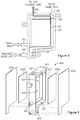
- FIG. 1 is an exploded, perspective view of an example defrothing device
- FIG. 2 is a cross-sectional view of the example defrothing device of FIG. 1 taken along 2 - 2 ;
- FIG. 3 is another perspective view of the example defrothing device of FIG. 1 with the filter screen and the cover layer removed;
- FIG. 4 is a schematic illustration of the example defrothing device of FIG. 1 illustrating various principles described herein;
- FIG. 5 is a plan view illustrating operation of the example defrothing device of Figure
- FIG. 6 is an exploded, perspective view of another example defrothing device
- FIG. 7 illustrates an example vent structure of an example defrothing device
- FIG. 8 illustrates another example vent structure of an example defrothing device
- FIG. 9 is a flow chart illustrating an example process for processing of coalescing froth.
- a device receives a froth, as may be formed in a fluid such as ink, and separates the froth into a coalesced fluid and air.
- the coalesced fluid may be collected and re-circulated to a fluid reservoir, such as an ink supply, and the air may be vented to the atmosphere.
- a fluid reservoir such as an ink supply
- an example device is formed of a frame having an inner chamber into which froth may be directed and an outer chamber for receiving the coalesced fluid.
- the inner chamber is defined at least in part by a filter screen mounted on a recessed rim within the frame
- the outer chamber is defined at least in part by the filter screen and an outer cover layer mounted on an outer rim of the frame.
- the inner chamber is sized to facilitate breaking of the bubbles in the froth.
- the inner chamber has a width sized to accommodate bubbles in the froth such that the bubbles are substantially in a single-wide formation.
- froth may be found in many fluids.
- a backpressure may be desirable in an ink printhead.
- air is introduced into the printhead.
- the mixture of the ink and air generates froth within the printhead.
- froth can exist in any fluid processing system.
- some devices such as industrial cleaning devices use liquid detergent to clean components of the system. These devices similarly contain a froth layer due to the incorporation of air, surfactants, or other components.
- froth can impact the functionality of the system.
- froth may reduce the accuracy of certain sensors such as an ink-level gauge or a sensor that indicates that the system is out of ink.
- the accuracy of these sensors and gauges impacts user satisfaction, system performance, and system reliability.
- the froth present in an ink supply could prematurely trigger an out-of-ink sensor.
- Such a premature triggering of the sensor could lead to the replacement of an ink supply prior to its exhaustion, which is an inefficient use of ink and may create an impression on the customer that an ink supply drains sooner than it actually does.
- premature triggering of an ink sensor could also lead to failure of the printing system.
- Some systems have implemented a batch froth dissipation system wherein froth accumulates and dissipates over time and is gravity-fed back into the system.
- this system relies on time to dissipate the froth, and a lag is accordingly introduced between froth accumulation and coalescence.
- a lag is accordingly introduced between froth accumulation and coalescence.
- Such a lag in addition to being inefficient, also leads to erroneous fluid level readings.
- the present disclosure describes example devices and methods for coalescing a frothy fluid into coalesced fluid and air.
- the present disclosure describes a system that continuously, and not in a batched or periodic fashion, coalesces a frothy fluid.
- the function of the corresponding system in general is improved, specifically the accuracy of system sensors is improved, which leads to improved system performance, increased customer satisfaction, and improved fluid efficiency.
- FIGS. 1 and 2 illustrate an example defrothing device 100 .
- the example device 100 includes a frame 110 with various features formed therein.
- the frame 110 is generally in the shape of a rectangular box, but various other shapes are possible and are contemplated within the scope of the present disclosure.
- the frame 110 may be formed of a molded plastic or various other materials.
- Various features of the frame are provided to facilitate coalescing of a froth directed into the frame 110 .
- the frame 110 is provided with a wall 112 on one side of the frame 110 .
- the opposite side of the frame 110 is open and provided with an outer opening 120 defined by an outer rim 122 which substantially forms the perimeter of the outer opening 120 .
- the outer rim 122 of the outer opening 120 is also the outer perimeter of the frame 110 .
- the outer rim 122 of the outer opening may be separate from the outer-most portion of the frame.
- the example frame 110 of the example defrothing device 100 of FIGS. 1 and 2 further includes an inner opening 130 defined by an inner rim 132 which substantially forms the perimeter of the inner opening 130 .
- the inner opening 130 of the example frame 110 is recessed from the outer opening 120 , as most clearly illustrated in the cross-sectional view of FIG. 2 .
- the distance between the wall 112 of the frame 110 and the outer rim 122 is greater than the distance between the wall 112 and the inner rim 132 .
- a filter screen 140 is mounted on the perimeter of the inner opening 130 to form an inner chamber 134 .
- the filter screen 140 may be mounted to the inner rim 132 in any of a variety of manners.
- the filter screen 140 may be attached by heat staking it the inner rim 132 .
- other manners of attachment of the filter screen 140 are possible and are contemplated within the scope of the present disclosure.
- the filter screen 140 may be formed of a variety of materials, including metal or plastic, for example. As described in greater detail below, the filter screen 140 may be used to dissipate bubbles in a froth that may be introduced into the inner chamber 134 .
- the filter screen 140 may include pores to allow coalesced fluid to pass therethrough but prevents froth (e.g., bubbles) from passing.
- the size, shape and distribution of the pores in the filter screen 140 may be selected based on a variety of factors such as the type of fluid and expected flow rate of the froth, for example. Similar factors may be used to select the size and shape of the inner chamber 134 . For example, a larger and taller inner chamber 134 may be desirable for a higher flow rate of froth therethrough.
- the example defrothing device 100 is provided with a cover layer 150 mounted on the perimeter of the outer opening 120 to form an outer chamber 124 .
- the cover layer 150 may be mounted to the outer rim 122 in any of a variety of manners, such as by heat staking it the outer rim 122 .
- the cover layer 150 may be formed of a variety of materials that prevent a fluid from passing therethrough.
- the cover layer 150 may be a film formed of a metal or a plastic.
- the inner chamber 134 is defined at least in part by the wall 112 of the frame 110 on a first side and the filter screen 140 on a second side, the second side being opposite the first side.
- the outer chamber 124 is defined at least in part by the filter screen 140 on one side and the cover layer 150 on the opposite side.
- the filter screen 140 separates the inner chamber 134 and the outer chamber 124 .
- FIG. 3 a perspective view of the frame 110 of the defrothing device 100 of FIGS. 1 and 2 is illustrated from another perspective.
- FIG. 3 provides a view of the frame 110 with the filter screen 140 and the cover layer 150 removed.
- the frame 110 is provided with an inlet port 310 through which froth may be introduced into the defrothing device 100 .
- the inlet port 310 extends from the outside of the frame 110 and into the inner chamber 134 which is formed when the filter screen (not shown in FIG. 3 ) is mounted to the inner rim 132 .
- the inlet port is positioned near the bottom portion of the inner chamber 134 .
- the frame 110 is further provided with an outlet port 320 through which coalesced fluid may be directed out of the defrothing device 100 to, for example, a reservoir for the fluid.
- the outlet port 320 extends from the outer chamber 124 (which is formed when the filter screen and the outer layer are mounted) and through the frame 110 to outside the frame. As illustrated in the example of FIG. 3 , the outlet port is positioned near the bottom portion of the outer chamber 124 . In the example illustrated in FIG. 3 , the frame 110 is formed to provide a sump portion 126 of the outer chamber 124 . Thus, as the coalesced fluid crosses the filter screen into the outer chamber, gravity causes the fluid to travel downward and into the sump portion 126 . Accordingly, the outlet port 320 is located at the sump portion 126 of the outer chamber 124 .
- the frame 110 is provided with vents 330 , 340 to allow air to escape from the defrothing device 100 .
- vents 330 , 340 to allow air to escape from the defrothing device 100 .
- FIG. 4 a schematic illustration of the example defrothing device of FIGS. 1-3 illustrates principles of defrothing.
- FIG. 4 illustrates only a portion of the defrothing device, including the wall 112 , the filter screen 140 , the inner chamber 134 , and the vent 330 .
- Froth is illustrated in the inner chamber 134 in the form of bubbles 410 .
- the width of the inner chamber 134 between the wall 112 of the frame 110 and the filter screen 140 is sized to facilitate coalescing of the fluid in the froth.
- froth enters at a low point of the inner chamber 134 (e.g., through the inlet port 310 shown in FIG. 3 ) and is driven up the inner chamber.
- the width 136 of the inner chamber 134 is sized to accommodate bubbles in the froth such that the bubbles are substantially in a single-wide formation. This arrangement speeds the bubbles through the inner chamber and facilitates thinning of the bubbles 410 .
- the width 136 of the inner chamber 134 may also cause exertion of pressure on the walls of the bubbles 410 , thus abrading the bubbles 410 against the rough porous surface of the filter screen 140 , causing rupture of the surface of the bubbles 410 .
- a plan view of the example defrothing device 100 illustrates operation of the defrothing device 100 .
- froth is introduced into the example defrothing device 100 through the inlet port 310 into the bottom portion of the inner chamber 134 .
- the bubbles of the froth are broken, and the coalesced fluid passes through the filter screen (not shown in FIG. 5 ) and into the outer chamber.
- the coalesced fluid is collected in the sump portion 126 of the outer chamber and may be directed out of the defrothing device 100 through the outlet port 320 .
- the air resulting from the breaking of the bubbles in the froth is vented through the vents 330 and 340 to the atmosphere.
- the example defrothing device 600 of FIG. 6 is similar to the defrothing device 100 described above with reference to FIGS. 1-5 , but provided a two-sided filtration of the coalesced fluid. Accordingly, the example defrothing device 600 of FIG. 6 includes a frame 610 which is open on both sides. In this regard, the frame 610 is provided with an outer opening 620 defined by an outer rim 622 which substantially forms the perimeter of the outer opening 620 . While the perspective view shown in FIG. 6 only shows the outer opening 620 on one side, a similar outer opening with an outer rim is provided on the opposite side.
- the example frame 610 of the example defrothing device 600 of FIG. 6 further includes an inner opening 630 defined by an inner rim 632 which substantially forms the perimeter of the inner opening 630 .
- the inner opening 630 of the example frame 610 is recessed from the outer opening 620 . Again, the perspective view of FIG. 6 only shows the inner opening 630 on one side.
- a similar inner opening with an inner rim is provided on the opposite side and is recessed from the outer opening on the opposite side.
- Filter screens 640 a , 640 b are mounted on the perimeter of inner openings 630 on each side to form an inner chamber 634 .
- the example defrothing device 600 is provided with cover layers 650 a , 650 b mounted on the perimeter of outer openings 620 on each side to form an outer chamber 624 on each side.
- the outer chambers 624 on each side may merge with a single sump portion 626 provided near the bottom portion of the frame 610 .
- the inner chamber 634 is defined at least in part by the one filter screen 640 a on a first side and another filter screen 640 b on a second side, the second side being opposite the first side.
- each outer chamber 624 is defined at least in part by one filter screen 640 a , 640 b on one side and one cover layer 650 a , 650 b on the opposite side.
- a filter screen 640 separates the inner chamber 634 and each outer chamber 624 .
- a frame 710 of an example defrothing device may be provided with a vent 740 which allows air from the defrothing device to vent to the atmosphere.
- the vent 740 may be circular is shape and have a diameter of between about 1 mm and about 3 mm or, or more preferably, between about 1.5 mm and about 2 mm.
- the vent 740 of the frame 710 of FIG. 7 is covered with a membrane 750 provided on the outer surface of the frame 710 .
- the membrane 750 is formed of a material which allows air (or gas) to pass therethrough but prevents passage of a fluid.
- the membrane is formed of an oleophobic material and, therefore, prevents water, oil or other fluids from passing therethrough.
- a frame 810 of an example defrothing device may be provided with a vent 840 which allows air from the defrothing device to vent to the atmosphere.
- the vent 840 is covered with a membrane 850 provided on the outer surface of the frame 810 .
- the membrane 850 is formed of a material which allows air (or gas) to pass therethrough but prevents passage of a fluid, such as an oleophobic material.
- a labyrinth 860 is formed on the outer surface of the frame 810 .
- the labyrinth 860 extends from the vent 840 to a termination vent 862 .
- a cover 870 is mounted on the outer surface of the frame 810 and covers at least the labyrinth but allows the termination vent to be exposed to the atmosphere.
- the cover 870 is formed of a material with air-barrier properties. In this regard, the cover 870 reduces the water vapor transmission rate (WVTR) from the defrothing device.
- WVTR water vapor transmission rate
- the labyrinth 860 forms a long path with a small cross-sectional area to slow down the evaporation rate of any fluid in the chamber or system.
- the labyrinth 860 reduces the evaporation rate by creating a gradient between a fully humidified region at the beginning of the labyrinth 860 near the vent 840 and atmospheric air at the termination vent 862 at the end of the labyrinth 860 .
- a flow chart illustrates an example method for froth coalescing.
- the example method 900 may be implemented in various devices, including the example devices described above with reference to FIGS. 1-8 .
- froth is received in a first chamber (block 910 ).
- a first chamber for example, with reference to the example defrothing device 100 of FIGS. 1-5 , froth may be received in the inner chamber 134 through the inlet port 310 .
- coalesced fluid from the froth is received in a second chamber from the first chamber through a filter screen (block 920 ).
- the froth is separated into fluid and air by breaking of the bubbles.
- the coalesced fluid passes through the filter screen 140 into the outer chamber 124 .
- air is vented from the first chamber through a vent that is in communication with the first chamber (block 930 ).
- breaking of bubbles in the inner chamber results in the separation of coalesced fluid and air.
- the coalesced fluid is passed through the filter screen 140 into the outer chamber 124 .
- the air is vented from the inner chamber 134 through the vents 330 , 340 to the atmosphere.
- defrothing devices can continuously process froth.
- the froth can be efficiently separated into coalesced fluid and air.
- the coalesced fluid can be directed to a reservoir for use, and the air can be vented to the atmosphere, for example.
Landscapes
- Chemical & Material Sciences (AREA)
- Chemical Kinetics & Catalysis (AREA)
- Dispersion Chemistry (AREA)
- Degasification And Air Bubble Elimination (AREA)
Applications Claiming Priority (1)
| Application Number | Priority Date | Filing Date | Title |
|---|---|---|---|
| PCT/US2016/041712 WO2018013071A1 (en) | 2016-07-11 | 2016-07-11 | Froth coalescing |
Publications (2)
| Publication Number | Publication Date |
|---|---|
| US20190134988A1 US20190134988A1 (en) | 2019-05-09 |
| US10661577B2 true US10661577B2 (en) | 2020-05-26 |
Family
ID=60953221
Family Applications (1)
| Application Number | Title | Priority Date | Filing Date |
|---|---|---|---|
| US16/093,452 Active US10661577B2 (en) | 2016-07-11 | 2016-07-11 | Froth coalescing |
Country Status (4)
| Country | Link |
|---|---|
| US (1) | US10661577B2 (de) |
| EP (1) | EP3436174B1 (de) |
| CN (1) | CN109069953B (de) |
| WO (1) | WO2018013071A1 (de) |
Cited By (2)
| Publication number | Priority date | Publication date | Assignee | Title |
|---|---|---|---|---|
| US11117073B2 (en) * | 2016-07-11 | 2021-09-14 | Hewlett-Packard Development Company, L.P. | Froth coalescing vent |
| NL2028210B1 (en) * | 2021-05-12 | 2022-11-29 | Canon Kk | A fluid distribution device for an inkjet print head assembly |
Citations (16)
| Publication number | Priority date | Publication date | Assignee | Title |
|---|---|---|---|---|
| SU524557A1 (ru) | 1974-03-05 | 1976-08-15 | Институт Неорганической Химии Со Ан Ссср | Способ разрушени пены |
| US5252229A (en) | 1990-06-18 | 1993-10-12 | Institut Francais Du Petrole | Method and a device for separating a continuous fluid phase from a dispersed phase |
| JPH05277304A (ja) | 1992-03-31 | 1993-10-26 | Kawasaki Steel Corp | 循環管路における連続消泡方法 |
| US6234621B1 (en) | 1998-12-14 | 2001-05-22 | Scitex Digital Printing, Inc. | Foamless ramps for controlling the flow of ink to eliminate foam in an ink tank |
| US6454835B1 (en) | 2000-06-02 | 2002-09-24 | Scitex Digital Printing, Inc. | Two-phase flow separator |
| EP1322395A1 (de) | 2000-09-13 | 2003-07-02 | Mykrolis Corporation | Vorrichtung zum filtern von flüssigen medien |
| US20040066434A1 (en) * | 2002-10-03 | 2004-04-08 | Xerox Corporation | Reduced leakage ink container opening |
| US20060061637A1 (en) * | 2004-09-22 | 2006-03-23 | Therien Patrick J | Vent chamber |
| US20060090645A1 (en) * | 2004-10-29 | 2006-05-04 | Kent Blair M | Fluid-gas separator |
| US20070006735A1 (en) * | 2005-07-11 | 2007-01-11 | David Olsen | Separation of liquid and gas from froth |
| US20090251507A1 (en) | 2008-04-03 | 2009-10-08 | Kinpo Electronics, Inc. | Microparticle/aerosol-collecting device for office machine |
| US20100079559A1 (en) | 2008-09-29 | 2010-04-01 | Greg Justice | Fluid Circulation System |
| US20120007916A1 (en) | 2010-07-08 | 2012-01-12 | Seiko Epson Corporation | Mist collection device, liquid ejecting apparatus, and method for controlling mist collection device |
| US8439489B2 (en) | 2007-10-12 | 2013-05-14 | Videojet Technologies Inc. | Filter for ink supply system |
| JP2013158962A (ja) | 2012-02-02 | 2013-08-19 | Sii Printek Inc | フィルターユニット、液体噴射ヘッド及び液体噴射装置 |
| US20150266305A1 (en) | 2012-10-30 | 2015-09-24 | Hewlett-Packard Development Company, L.P. | Ink aerosol filtration |
Family Cites Families (4)
| Publication number | Priority date | Publication date | Assignee | Title |
|---|---|---|---|---|
| JPH04141205A (ja) * | 1990-10-03 | 1992-05-14 | Mitsubishi Heavy Ind Ltd | 脱泡装置 |
| CN101052458B (zh) * | 2004-10-22 | 2011-11-30 | 惠普开发有限公司 | 流体-气体分离器 |
| KR100626802B1 (ko) * | 2006-03-15 | 2006-09-20 | 소우섭 | 접합재의 기포 제거를 위한 표면활성제 및 이를 이용한접합방법 |
| CN204185236U (zh) * | 2014-09-29 | 2015-03-04 | 比亚迪股份有限公司 | 除泡装置 |
-
2016
- 2016-07-11 WO PCT/US2016/041712 patent/WO2018013071A1/en active Application Filing
- 2016-07-11 EP EP16908976.0A patent/EP3436174B1/de active Active
- 2016-07-11 CN CN201680085225.9A patent/CN109069953B/zh not_active Expired - Fee Related
- 2016-07-11 US US16/093,452 patent/US10661577B2/en active Active
Patent Citations (17)
| Publication number | Priority date | Publication date | Assignee | Title |
|---|---|---|---|---|
| SU524557A1 (ru) | 1974-03-05 | 1976-08-15 | Институт Неорганической Химии Со Ан Ссср | Способ разрушени пены |
| US5252229A (en) | 1990-06-18 | 1993-10-12 | Institut Francais Du Petrole | Method and a device for separating a continuous fluid phase from a dispersed phase |
| JPH05277304A (ja) | 1992-03-31 | 1993-10-26 | Kawasaki Steel Corp | 循環管路における連続消泡方法 |
| US6234621B1 (en) | 1998-12-14 | 2001-05-22 | Scitex Digital Printing, Inc. | Foamless ramps for controlling the flow of ink to eliminate foam in an ink tank |
| US6454835B1 (en) | 2000-06-02 | 2002-09-24 | Scitex Digital Printing, Inc. | Two-phase flow separator |
| EP1322395A1 (de) | 2000-09-13 | 2003-07-02 | Mykrolis Corporation | Vorrichtung zum filtern von flüssigen medien |
| US20040066434A1 (en) * | 2002-10-03 | 2004-04-08 | Xerox Corporation | Reduced leakage ink container opening |
| US7726786B2 (en) | 2004-09-22 | 2010-06-01 | Hewlett-Packard Development Company, L.P. | Vent chamber |
| US20060061637A1 (en) * | 2004-09-22 | 2006-03-23 | Therien Patrick J | Vent chamber |
| US20060090645A1 (en) * | 2004-10-29 | 2006-05-04 | Kent Blair M | Fluid-gas separator |
| US20070006735A1 (en) * | 2005-07-11 | 2007-01-11 | David Olsen | Separation of liquid and gas from froth |
| US8439489B2 (en) | 2007-10-12 | 2013-05-14 | Videojet Technologies Inc. | Filter for ink supply system |
| US20090251507A1 (en) | 2008-04-03 | 2009-10-08 | Kinpo Electronics, Inc. | Microparticle/aerosol-collecting device for office machine |
| US20100079559A1 (en) | 2008-09-29 | 2010-04-01 | Greg Justice | Fluid Circulation System |
| US20120007916A1 (en) | 2010-07-08 | 2012-01-12 | Seiko Epson Corporation | Mist collection device, liquid ejecting apparatus, and method for controlling mist collection device |
| JP2013158962A (ja) | 2012-02-02 | 2013-08-19 | Sii Printek Inc | フィルターユニット、液体噴射ヘッド及び液体噴射装置 |
| US20150266305A1 (en) | 2012-10-30 | 2015-09-24 | Hewlett-Packard Development Company, L.P. | Ink aerosol filtration |
Cited By (2)
| Publication number | Priority date | Publication date | Assignee | Title |
|---|---|---|---|---|
| US11117073B2 (en) * | 2016-07-11 | 2021-09-14 | Hewlett-Packard Development Company, L.P. | Froth coalescing vent |
| NL2028210B1 (en) * | 2021-05-12 | 2022-11-29 | Canon Kk | A fluid distribution device for an inkjet print head assembly |
Also Published As
| Publication number | Publication date |
|---|---|
| CN109069953B (zh) | 2021-11-26 |
| WO2018013071A1 (en) | 2018-01-18 |
| EP3436174A4 (de) | 2019-11-13 |
| US20190134988A1 (en) | 2019-05-09 |
| EP3436174A1 (de) | 2019-02-06 |
| CN109069953A (zh) | 2018-12-21 |
| EP3436174B1 (de) | 2021-07-07 |
Similar Documents
| Publication | Publication Date | Title |
|---|---|---|
| US10661201B2 (en) | Froth coalescing | |
| US8177341B2 (en) | Liquid injecting method and liquid container | |
| US10661577B2 (en) | Froth coalescing | |
| EP2221462A1 (de) | Mehrkammer-Kühlmitteltank | |
| US20080012915A1 (en) | Liquid storage container | |
| US5632864A (en) | Splash shield for distillation unit | |
| JP2008068614A (ja) | 液体注入方法及び液体収容容器 | |
| WO2014136501A1 (ja) | インクジェット記録装置 | |
| KR200371804Y1 (ko) | 에어 필터 장치 | |
| US11117073B2 (en) | Froth coalescing vent | |
| US11083982B2 (en) | Coalescing frothy fluids | |
| US20190001700A1 (en) | Coalescing frothy fluids | |
| JP2013029041A (ja) | ドレン処理装置及びドレン処理方法 | |
| EP3960269B1 (de) | Filtervorrichtung | |
| JP2003170004A (ja) | 充填タンク脱気装置 | |
| KR20170032653A (ko) | 상 분리 장치 | |
| KR101391013B1 (ko) | 윤활유 회수용 유수 분리 장치 | |
| JP6126050B2 (ja) | 分離槽 | |
| KR20150019059A (ko) | 친수성 다공성 멤브레인을 포함하는 연료전지용 기액분리장치 | |
| EP2109542A1 (de) | Tintenbehälter | |
| JP2007256877A (ja) | スペーサ回収機 |
Legal Events
| Date | Code | Title | Description |
|---|---|---|---|
| FEPP | Fee payment procedure |
Free format text: ENTITY STATUS SET TO UNDISCOUNTED (ORIGINAL EVENT CODE: BIG.); ENTITY STATUS OF PATENT OWNER: LARGE ENTITY |
|
| AS | Assignment |
Owner name: HEWLETT-PACKARD DEVELOPMENT COMPANY, L.P., TEXAS Free format text: ASSIGNMENT OF ASSIGNORS INTEREST;ASSIGNORS:STUDER, ANTHONY;WICKWIRE, ROBERT;REEL/FRAME:048015/0134 Effective date: 20160708 |
|
| STPP | Information on status: patent application and granting procedure in general |
Free format text: NON FINAL ACTION MAILED |
|
| STPP | Information on status: patent application and granting procedure in general |
Free format text: RESPONSE TO NON-FINAL OFFICE ACTION ENTERED AND FORWARDED TO EXAMINER |
|
| STPP | Information on status: patent application and granting procedure in general |
Free format text: NOTICE OF ALLOWANCE MAILED -- APPLICATION RECEIVED IN OFFICE OF PUBLICATIONS |
|
| STPP | Information on status: patent application and granting procedure in general |
Free format text: PUBLICATIONS -- ISSUE FEE PAYMENT VERIFIED |
|
| STCF | Information on status: patent grant |
Free format text: PATENTED CASE |
|
| MAFP | Maintenance fee payment |
Free format text: PAYMENT OF MAINTENANCE FEE, 4TH YEAR, LARGE ENTITY (ORIGINAL EVENT CODE: M1551); ENTITY STATUS OF PATENT OWNER: LARGE ENTITY Year of fee payment: 4 |