US11117073B2 - Froth coalescing vent - Google Patents
Froth coalescing vent Download PDFInfo
- Publication number
- US11117073B2 US11117073B2 US16/093,440 US201616093440A US11117073B2 US 11117073 B2 US11117073 B2 US 11117073B2 US 201616093440 A US201616093440 A US 201616093440A US 11117073 B2 US11117073 B2 US 11117073B2
- Authority
- US
- United States
- Prior art keywords
- defrothing
- membrane
- vent
- air
- labyrinth
- Prior art date
- Legal status (The legal status is an assumption and is not a legal conclusion. Google has not performed a legal analysis and makes no representation as to the accuracy of the status listed.)
- Active, expires
Links
Images


Classifications
-
- B—PERFORMING OPERATIONS; TRANSPORTING
- B01—PHYSICAL OR CHEMICAL PROCESSES OR APPARATUS IN GENERAL
- B01D—SEPARATION
- B01D19/00—Degasification of liquids
- B01D19/0031—Degasification of liquids by filtration
-
- B—PERFORMING OPERATIONS; TRANSPORTING
- B01—PHYSICAL OR CHEMICAL PROCESSES OR APPARATUS IN GENERAL
- B01D—SEPARATION
- B01D19/00—Degasification of liquids
- B01D19/0042—Degasification of liquids modifying the liquid flow
-
- B—PERFORMING OPERATIONS; TRANSPORTING
- B01—PHYSICAL OR CHEMICAL PROCESSES OR APPARATUS IN GENERAL
- B01D—SEPARATION
- B01D19/00—Degasification of liquids
- B01D19/02—Foam dispersion or prevention
-
- B—PERFORMING OPERATIONS; TRANSPORTING
- B01—PHYSICAL OR CHEMICAL PROCESSES OR APPARATUS IN GENERAL
- B01D—SEPARATION
- B01D63/00—Apparatus in general for separation processes using semi-permeable membranes
- B01D63/08—Flat membrane modules
- B01D63/087—Single membrane modules
-
- B—PERFORMING OPERATIONS; TRANSPORTING
- B01—PHYSICAL OR CHEMICAL PROCESSES OR APPARATUS IN GENERAL
- B01D—SEPARATION
- B01D69/00—Semi-permeable membranes for separation processes or apparatus characterised by their form, structure or properties; Manufacturing processes specially adapted therefor
- B01D69/02—Semi-permeable membranes for separation processes or apparatus characterised by their form, structure or properties; Manufacturing processes specially adapted therefor characterised by their properties
-
- B—PERFORMING OPERATIONS; TRANSPORTING
- B01—PHYSICAL OR CHEMICAL PROCESSES OR APPARATUS IN GENERAL
- B01D—SEPARATION
- B01D69/00—Semi-permeable membranes for separation processes or apparatus characterised by their form, structure or properties; Manufacturing processes specially adapted therefor
- B01D69/06—Flat membranes
-
- B—PERFORMING OPERATIONS; TRANSPORTING
- B41—PRINTING; LINING MACHINES; TYPEWRITERS; STAMPS
- B41J—TYPEWRITERS; SELECTIVE PRINTING MECHANISMS, i.e. MECHANISMS PRINTING OTHERWISE THAN FROM A FORME; CORRECTION OF TYPOGRAPHICAL ERRORS
- B41J2/00—Typewriters or selective printing mechanisms characterised by the printing or marking process for which they are designed
- B41J2/005—Typewriters or selective printing mechanisms characterised by the printing or marking process for which they are designed characterised by bringing liquid or particles selectively into contact with a printing material
- B41J2/01—Ink jet
- B41J2/17—Ink jet characterised by ink handling
- B41J2/175—Ink supply systems ; Circuit parts therefor
- B41J2/17563—Ink filters
-
- B—PERFORMING OPERATIONS; TRANSPORTING
- B41—PRINTING; LINING MACHINES; TYPEWRITERS; STAMPS
- B41J—TYPEWRITERS; SELECTIVE PRINTING MECHANISMS, i.e. MECHANISMS PRINTING OTHERWISE THAN FROM A FORME; CORRECTION OF TYPOGRAPHICAL ERRORS
- B41J2/00—Typewriters or selective printing mechanisms characterised by the printing or marking process for which they are designed
- B41J2/005—Typewriters or selective printing mechanisms characterised by the printing or marking process for which they are designed characterised by bringing liquid or particles selectively into contact with a printing material
- B41J2/01—Ink jet
- B41J2/17—Ink jet characterised by ink handling
- B41J2/19—Ink jet characterised by ink handling for removing air bubbles
-
- B—PERFORMING OPERATIONS; TRANSPORTING
- B01—PHYSICAL OR CHEMICAL PROCESSES OR APPARATUS IN GENERAL
- B01D—SEPARATION
- B01D2325/00—Details relating to properties of membranes
- B01D2325/36—Hydrophilic membranes
Definitions
- Froth is a common occurrence in many fluids. Froth is a mass of bubbles in a fluid, or on the surface of the fluid. Froth can form as air is incorporated into the fluid. For example, in ink printing systems, as air is introduced into an ink reservoir to maintain pressure, froth may form in the corpus of the ink or on a surface of the ink. Froth is also found in other fluids, for example detergents or liquid soaps. Such froth may inhibit the operations of a system that processes fluids that are susceptible to froth formation
- FIG. 1 is a perspective view of an example defrothing device
- FIG. 2 is a perspective view of another example defrothing device
- FIG. 3 is a top plan view of an example defrothing device
- FIG. 4 is a cross-sectional view of the example defrothing device of FIG. 3 taken along 4 - 4 ;
- FIG. 5 is a top plan view of an example defrothing device
- FIG. 6 is a cross-sectional view of the example defrothing device of FIG. 5 taken along 6 - 6 ;
- FIG. 7 is a detailed plan view of an example vent structure for the example defrothing device of FIG. 5 ;
- FIG. 8 is a top plan view of an example defrothing device
- FIG. 9 is a cross-sectional view of the example defrothing device of FIG. 8 taken along 9 - 9 ;
- FIG. 10 is a perspective, exploded view of an example defrothing device
- FIG. 11 is a cross-sectional view of the example defrothing device of FIG. 10 taken along 11 - 11 ;
- FIG. 12 is a schematic illustration of the example defrothing device of FIG. 10 illustrating various operating principles
- FIG. 13 is a perspective, exploded view of another example defrothing device
- FIG. 14 is a cross-sectional view of the example defrothing device of FIG. 13 taken along 14 - 14 ;
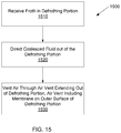
- FIG. 15 is a flow chart illustrating an example process for coalescing froth.
- a device receives a froth, as may be formed in a fluid such as ink, and separates the froth into a coalesced fluid and air.
- the coalesced fluid may be collected and re-circulated to a fluid reservoir, such as an ink supply, and the air may be vented to the atmosphere.
- the air is directed out of the defrothing device through an air vent extending to the outside surface of the defrothing device.
- a membrane is provided on the outside surface covering the air vent. The membrane allows air to pass therethrough, but prevents any fluid that may have reached the air vent from passing therethrough.
- a labyrinth may be formed on the outside surface and may be in fluidic communication with the air vent.
- the labyrinth provides a long narrow channel which may facilitate venting of air but minimizing fluid loss by reducing evaporation of the fluid.
- a cover with air-barrier properties may be provided to cover at least a portion of the labyrinth.
- froth may be found in many fluids.
- a backpressure may be desirable in an ink printhead.
- air is introduced into the printhead.
- the mixture of the ink and air generates froth within the printhead.
- froth can exist in any fluid processing system.
- some devices such as industrial cleaning devices use liquid detergent to clean components of the system. These devices similarly contain a froth layer due to the incorporation of air, surfactants, or other components.
- froth can impact the functionality of the system.
- froth may reduce the accuracy of certain sensors such as an ink-level gauge or a sensor that indicates that the system is out of ink.
- the accuracy of these sensors and gauges impacts user satisfaction, system performance, and system reliability.
- the froth present in an ink supply could prematurely trigger an out-of-ink sensor.
- Such a premature triggering of the sensor could lead to the replacement of an ink supply prior to its exhaustion, which is an inefficient use of ink and may create an impression on the customer that an ink supply drains sooner than it actually does.
- premature triggering of an ink sensor could also lead to failure of the printing system.
- the present disclosure describes example devices and methods for coalescing a frothy fluid into coalesced fluid and air.
- the present disclosure describes devices which include a defrothing portion to separate the froth into coalesced liquid and air. The air is allowed to vent, while loss of the fluid through the air vent is reduced, minimized or eliminated.
- FIG. 1 illustrates an example defrothing device.
- the example defrothing device 100 is provided with a defrothing portion 110 .
- the defrothing portion 110 may receive froth and separate the froth into coalesced fluid (e.g., a liquid) and air. While the coalesced fluid may drop to the bottom of the defrothing portion 110 due to gravity, the air may travel to the top of the defrothing portion 110 .
- the example defrothing device 100 is provided with a vent 120 at the top of the defrothing portion 110 which may be in fluidic communication with a vent 130 leading to an outer surface 112 of the example defrothing device 100 .
- a vent 120 at the top of the defrothing portion 110 which may be in fluidic communication with a vent 130 leading to an outer surface 112 of the example defrothing device 100 .
- the vent 130 may be circular is shape and have a diameter of between about 1 mm and about 3 mm or, or more preferably, between about 1.5 mm and about 2 mm
- the air separated from the froth may be vented to the atmosphere, for example.
- a membrane 140 may be provided on the outer surface 112 of the example defrothing device 100 .
- the membrane 140 is positioned to substantially completely cover and seal the air vent 130 .
- the membrane 140 may be adhered to the outer surface 112 of the example defrothing device 100 in any of a variety of manners.
- the membrane 140 is formed of a material which allows air to pass therethrough but prevents a fluid, such as liquid ink, from passing therethrough.
- the membrane 140 is formed of an oleophobic material which inhibits, reduces or minimizes passage of water, oil or other fluids therethrough.
- the example defrothing device 200 of FIG. 2 is similar to the example defrothing device 100 of FIG. 1 .
- the example defrothing device 200 of FIG. 2 includes a defrothing portion 210 , air vents 220 , 230 and a membrane (e.g., an oleophobic membrane) 240 positioned on the outer surface 212 of the example defrothing device 200 .
- a membrane e.g., an oleophobic membrane
- a labyrinth 250 is formed on the outer surface 212 of the example defrothing device 200 .
- the labyrinth 250 extends from the vent 230 to a termination vent 252 .
- the labyrinth 250 is in fluidic communication with the air vent 230 .
- a cover 260 is mounted on the outer surface 212 of the example defrothing device 200 and covers at least a part of the labyrinth 250 .
- the cover 260 is positioned to cover substantially the entire labyrinth 250 , but allows the termination vent 252 to be exposed to the atmosphere.
- the cover 260 is formed of a material with air-barrier properties.
- the cover 260 reduces the water vapor transmission rate (WVTR) from the example defrothing device 200 .
- WVTR water vapor transmission rate
- the labyrinth 250 forms a long path with a small cross-sectional area to slow down the evaporation rate of any fluid that may have reached the labyrinth 250 .
- the length of the labyrinth 250 may cover a length of at least about 30 mm, and the cross-sectional area of the labyrinth 250 may be less than about 1 mm 2 , but both values may be selected based on the desired reduction in WVTR.
- the evaporation rate of the fluid is reduced by creation of a gradient between a fully humidified region at the beginning of the labyrinth 250 near the vent 230 and atmospheric air at the termination vent 252 at the end of the labyrinth 250 .
- the example defrothing device 200 of FIG. 2 may be provided with a single component in place of the membrane 240 and the cover 260 .
- the membrane 240 may be removed, and the cover 260 may be provided to sufficiently cover the vent 230 and the labyrinth 250 .
- FIG. 3 provides a top plan view of the example defrothing device 300
- FIG. 4 provides a cross-sectional view of the example defrothing device 300 taken along 4 - 4
- the example defrothing device 300 is provided with a defrothing portion 310 and an outer surface 312 .
- the defrothing portion 310 includes a chamber 314 into which the froth may be directed for separation into a coalesced fluid and a gas.
- the coalesced fluid may be directed downward by gravity and collected in a sump portion 316 positioned near the bottom portion of the example defrothing device 300 .
- the separated gas may be directed upward out of the chamber 314 through a vent (not shown in FIGS. 3 and 4 ) into an upper chamber 318 .
- the gas may then escape the example defrothing device 300 through a vent 330 .
- the vent 330 is provided with a vent channel 340 that has a substantially circular cross section and extends from the upper chamber 318 to the vent 330 on the outer surface 312 of the example defrothing device 300 .
- a membrane may be provided on the outer surface 312 to seal the vent 330 .
- the membrane is not shown in FIGS. 3 and 4 for purposes of clarity.
- the upper chamber 318 and the vent 330 provide a path for the gas to exit the example defrothing device 300 .
- froth including gas and fluid
- froth may travel into the upper chamber 318 and the vent.
- the froth e.g., bubbles
- Certain examples of the present disclosure may provide features to mitigate this risk.
- FIGS. 5 and 6 illustrate an example defrothing device 500 with a vent structure having features which facilitate reducing the risk of blocking of the vent by froth or fluid.
- FIG. 5 provides a top plan view of the example defrothing device 500
- FIG. 6 provides a cross-sectional view of the example defrothing device 500 taken along 6 - 6 .
- the example defrothing device 500 is provided with a defrothing portion 510 and an outer surface 512 .
- the defrothing portion 510 includes a chamber 514 into which the froth may be directed for separation into a coalesced fluid and a gas.
- the coalesced fluid may be directed downward by gravity and collected in a sump portion 516 , and the separated gas may be directed upward out of the chamber 514 through a vent (not shown in FIGS. 5 and 6 ) into an upper chamber 518 .
- the gas may then escape the example defrothing device 500 through a vent 530 and a labyrinth 550 with a termination vent 552 .
- a membrane and/or a cover may be provided to seal the vent 530 and/or the labyrinth 550 .
- the vent 530 is provided with a vent channel 540 that extends from the upper chamber 518 to the vent 530 on the outer surface 512 .
- the vent channel 540 of FIGS. 5 and 6 is provided with a non-circular cross section.
- the vent channel 540 is provided with a cross section that has at least one corner, as most clearly illustrated in FIG. 5 .
- the cross section of the vent channel 540 includes at least one polygonal shape.
- FIG. 7 provides a detailed plan view of the example vent structure 530 of FIG. 5 .
- the vent structure 530 includes a vent channel 540 which extends to the outer surface 512 of the example defrothing device 500 .
- the vent channel 540 includes a polygonal section 542 in the middle of the cross section of the vent channel 540 .
- the polygonal section 542 is provided with a substantially octagonal shape.
- the polygonal section 542 illustrated in FIG. 7 forms at least four corners and provides a lower likelihood of complete blockage by froth or fluid when compared to a circular cross-section.
- vent channel 540 includes end portions 544 which include corners which may further prevent blockage by froth or fluid.
- the end portions 544 include sharp corners forming acute angles which discourage froth or liquid from settling therein.
- a rectangular connector portion 546 is provided between each end portion 544 and the polygonal section 542 . The substantially straight edges of the rectangular connection portion 546 also prevents froth or fluid from completely blocking flow of gas therethrough.
- vent channel 540 illustrated in FIG. 7 is only an example. Other shapes which inhibit complete blockage of the vent channel 540 are possible and are contemplated within the scope of the present disclosure.
- FIG. 8 provides a top plan view of the example defrothing device 800
- FIG. 9 provides a cross-sectional view of the example defrothing device 800 taken along 9 - 9
- the example defrothing device 800 is provided with a defrothing portion 810 and an outer surface 812 .
- the defrothing portion 810 includes a chamber 814 into which the froth may be directed for separation into a coalesced fluid and a gas.
- the coalesced fluid may be directed downward by gravity and collected in a sump portion 816 , and the separated gas may be directed upward out of the chamber 814 through a vent (not shown in FIGS.
- a membrane and/or a cover may be provided to seal the vent 830 and/or the labyrinth 850 .
- the vent 830 is provided with a vent channel 840 having a configuration similar to that described above with reference to FIG. 7 .
- the vent channel 840 is directly coupled to the labyrinth 850 .
- the vent channel 840 is positioned on one edge of the vent 830 , and the labyrinth 850 begins at the same edge of the vent 830 and ends with a termination vent 852 .
- the direct coupling of the vent channel 840 to the labyrinth 850 may further reduce the risk of complete blockage of a vent path by froth or fluid.
- the example device 1000 includes a frame 1010 with various features formed therein.
- the membrane covering the air vent is not shown in FIG. 3 .
- the frame 1010 is generally in the shape of a rectangular box, but various other shapes are possible and are contemplated within the scope of the present disclosure.
- the frame 1010 may be formed of a molded plastic or various other materials.
- Various features of the frame are provided to facilitate coalescing of a froth directed into the frame 1010 .
- the frame 1010 is provided with a wall 1012 on one side of the frame 1010 .
- the opposite side of the frame 1010 is open and provided with an outer opening 1020 defined by an outer rim 1022 which substantially forms the perimeter of the outer opening 1020 .
- the outer rim 1022 of the outer opening 1020 is also the outer perimeter of the frame 1010 .
- the outer rim 1022 of the outer opening may be separate from the outer-most portion of the frame.
- the example frame 1010 of the example defrothing device 1000 of FIGS. 10 and 11 further includes an inner opening 1030 defined by an inner rim 1032 which substantially forms the perimeter of the inner opening 1030 .
- the inner opening 1030 of the example frame 1010 is recessed from the outer opening 1020 , as most clearly illustrated in the cross-sectional view of FIG. 11 .
- the distance between the wall 1012 of the frame 1010 and the outer rim 1022 is greater than the distance between the wall 1012 and the inner rim 1032 .
- a filter screen 1040 is mounted on the perimeter of the inner opening 1030 to form an inner chamber 1034 .
- the filter screen 1040 may be mounted to the inner rim 1032 in any of a variety of manners.
- the filter screen 1040 may be attached by heat staking it the inner rim 1032 .
- other manners of attachment of the filter screen 1040 are possible and are contemplated within the scope of the present disclosure.
- the filter screen 1040 may be formed of a variety of materials, including metal or plastic, for example. As described in greater detail below, the filter screen 1040 may be used to dissipate bubbles in a froth that may be introduced into the inner chamber 1034 .
- the filter screen 1040 may include pores to allow coalesced fluid to pass therethrough but prevents froth (e.g., bubbles) from passing.
- the size, shape and distribution of the pores in the filter screen 1040 may be selected based on a variety of factors such as the type of fluid and expected flow rate of the froth, for example. Similar factors may be used to select the size and shape of the inner chamber 1034 . For example, a larger and taller inner chamber 1034 may be desirable for a higher flow rate of froth therethrough.
- the example defrothing device 1000 is provided with a cover layer 1050 mounted on the perimeter of the outer opening 1020 to form an outer chamber 1024 .
- the cover layer 1050 may be mounted to the outer rim 1022 in any of a variety of manners, such as by heat staking it the outer rim 1022 .
- the cover layer 1050 may be formed of a variety of materials that prevent a fluid from passing therethrough.
- the cover layer 1050 may be a film formed of a metal or a plastic.
- the inner chamber 1034 is defined at least in part by the wall 1012 of the frame 1010 on a first side and the filter screen 1040 on a second side, the second side being opposite the first side.
- the outer chamber 1024 is defined at least in part by the filter screen 1040 on one side and the cover layer 1050 on the opposite side.
- the filter screen 1040 separates the inner chamber 1034 and the outer chamber 1024 .
- the frame 1010 is provided with vents 1060 , 1070 , an inlet port 1080 and an outlet port 1090 .
- the inlet port 1080 is positioned near the bottom portion of the frame and extends into the inner chamber 1034 .
- froth may be directed into the inner chamber 1034 through the inlet port 1080 .
- the outlet port 1090 is positioned near the bottom portion of the frame and extends out of the outer chamber 1024 to allow coalesced fluid to be directed out of the outer chamber 1024 .
- the vents 1060 , 1070 allow air to escape from the defrothing device 1000 .
- the remaining air may be vented from the inner chamber 1034 through the vent 1060 and to the atmosphere through the vent 1070 .
- FIG. 12 a schematic illustration of the example defrothing device 1000 of FIGS. 10 and 11 illustrates principles of defrothing.
- FIG. 12 illustrates only a portion of the defrothing device 1000 , including the wall 1012 , the filter screen 1040 , the inner chamber 1034 , and the vent 1060 . Froth is illustrated in the inner chamber 1034 in the form of bubbles 1210 .
- the width of the inner chamber 1034 between the wall 1012 of the frame 1010 and the filter screen 1040 is sized to facilitate coalescing of the fluid in the froth.
- froth enters at a low point of the inner chamber 1034 and is driven up the inner chamber 1034 .
- the width 1220 of the inner chamber 1034 is sized to accommodate bubbles in the froth such that the bubbles are substantially in a single-wide formation. This arrangement speeds the bubbles through the inner chamber and facilitates thinning of the bubbles 1210 .
- the width 1220 of the inner chamber 1034 may also cause exertion of pressure on the walls of the bubbles 1210 , thus abrading the bubbles 1210 against the rough porous surface of the filter screen 1040 , causing rupture of the surface of the bubbles 1210 .
- the example device 1300 includes a frame 1310 with various features formed therein.
- the frame 1310 is provided with a wall 1312 on one side of the frame 1310 .
- the opposite side of the frame 1310 is open and provided with an outer opening 1320 defined by an outer rim 1322 which substantially forms the perimeter of the outer opening 1320 .
- the outer rim 1322 of the outer opening 1320 is also the outer perimeter of the frame 1310 .
- the outer rim 1322 of the outer opening may be separate from the outer-most portion of the frame.
- the example frame 1310 of the example defrothing device 1300 of FIGS. 13 and 14 further includes an inner opening 1330 defined by an inner rim 1332 which substantially forms the perimeter of the inner opening 1330 .
- the inner opening 1330 of the example frame 1310 is recessed from the outer opening 1320 , as most clearly illustrated in the cross-sectional view of FIG. 14 .
- the distance between the wall 1314 of the frame 1310 and the outer rim 1322 is greater than the distance between the wall 1312 and the inner rim 1332 .
- a filter screen 1340 is mounted on the perimeter of the inner opening 1330 to form an inner chamber 1334 .
- the example defrothing device 1300 is provided with a cover layer 1350 mounted on the perimeter of the outer opening 1320 to form an outer chamber 1324 .
- the example defrothing device 1300 of FIGS. 13 and 14 is provided with a series of bubble-breaking features 1360 positioned within the inner chamber 1334 .
- the bubble-breaking features 1360 are positioned along the depth (left to right in FIG. 13 ) and along the height (up to down in FIGS. 13 and 14 ) of the inner chamber 1334 .
- the bubble-breaking features 1360 are integrally formed with the frame 1310 .
- the frame 1310 may be molded with the bubble-breaking features 1360 formed on the wall 1312 of the frame 1310 .
- the size of the bubble-breaking features 1360 may increase with the height of the inner chamber 1334 .
- the width of the bubble-breaking features 1360 e.g., the magnitude of protrusion from the wall 1314
- the bubble-breaking features 1360 may progressively ensure breaking of smaller and smaller bubbles, with coalesced fluid being directed out of the outer chamber 1324 through an outlet port 1390 .
- the uppermost bubble-breaking features 1360 are sized to provide a gap between the bubble-breaking feature 1360 and the filter screen 1340 that is no greater than the size of a single bubble.
- the gap between the uppermost bubble-breaking features 1360 and the filter screen 1340 is sized such that the bubbles are substantially in a single-wide formation.
- the bubble-breaking features 1360 are formed in a chevron configuration.
- the example bubble-breaking features 1360 may be formed on the wall 1312 of a frame 1310 as an inverted v-shaped protrusions.
- the inverted v-shaped configuration of the example bubble-breaking features 1360 includes two side protrusions and a central post to facilitate breaking of bubbles traveling in the upward direction.
- FIGS. 10-14 illustrate some examples of defrothing devices that may be used in the example fluid supply systems described herein. Of course, various other defrothing devices are possible and are contemplated within the scope of the present disclosure.
- a flow chart illustrates an example method for froth coalescing.
- the example method 1500 may be implemented in various devices, including the example devices described above with reference to FIGS. 1-14 .
- froth is received in a defrothing portion of a defrothing device, where the defrothing portion is to separate froth into coalesced fluid and air (block 1510 ).
- froth may be received in the defrothing device 1000 through the inlet port 1080 .
- the froth is separated into a coalesced fluid and air in the defrothing device 1000 in the inner chamber 1034 , for example.
- coalesced fluid from the froth is directed out of the defrothing portion (block 1520 ).
- the coalesced fluid may be directed out of the defrothing device 1000 through the outlet port 1090 .
- air is vented from the defrothing portion through an air vent (block 1530 ).
- the air vent extends out of the defrothing portion and includes a membrane on an outer surface of the defrothing portion.
- air is vented through the air vent 130 .
- a membrane 140 is provided on the outer surface 112 of the defrothing device 100 .
- venting of air from a defrothing device is facilitated by features that prevent fluid (e.g., froth which includes air and fluid) from escaping the defrothing device.
- fluid e.g., froth which includes air and fluid
Abstract
Description
Claims (11)
Applications Claiming Priority (1)
| Application Number | Priority Date | Filing Date | Title |
|---|---|---|---|
| PCT/US2016/041715 WO2018013073A1 (en) | 2016-07-11 | 2016-07-11 | Froth coalescing vent |
Publications (2)
| Publication Number | Publication Date |
|---|---|
| US20190168134A1 US20190168134A1 (en) | 2019-06-06 |
| US11117073B2 true US11117073B2 (en) | 2021-09-14 |
Family
ID=60953223
Family Applications (1)
| Application Number | Title | Priority Date | Filing Date |
|---|---|---|---|
| US16/093,440 Active 2036-08-27 US11117073B2 (en) | 2016-07-11 | 2016-07-11 | Froth coalescing vent |
Country Status (4)
| Country | Link |
|---|---|
| US (1) | US11117073B2 (en) |
| EP (1) | EP3436175B1 (en) |
| CN (1) | CN109069952A (en) |
| WO (1) | WO2018013073A1 (en) |
Citations (19)
| Publication number | Priority date | Publication date | Assignee | Title |
|---|---|---|---|---|
| US5536413A (en) | 1990-12-03 | 1996-07-16 | Pall Corporation | Method for treating a parenteral emulsion-containing medicament fluid |
| DE19941271A1 (en) | 1999-08-31 | 2001-04-05 | Lienhard Pagel | Micro-fluid membrane module used in pH regulating systems has gas-permeable permeation membrane between micro-fluidic channels |
| US6234621B1 (en) | 1998-12-14 | 2001-05-22 | Scitex Digital Printing, Inc. | Foamless ramps for controlling the flow of ink to eliminate foam in an ink tank |
| EP1219333A1 (en) | 2000-12-28 | 2002-07-03 | Nipro Corporation | Air trap for liquid circulation line |
| US6454835B1 (en) | 2000-06-02 | 2002-09-24 | Scitex Digital Printing, Inc. | Two-phase flow separator |
| US20040165040A1 (en) * | 2003-02-24 | 2004-08-26 | Olsen David N. | Ink Reservoirs |
| US20060061637A1 (en) * | 2004-09-22 | 2006-03-23 | Therien Patrick J | Vent chamber |
| US20060165935A1 (en) * | 2005-01-21 | 2006-07-27 | Studer Anthony D | Selectively permeable membrane |
| US20070006735A1 (en) * | 2005-07-11 | 2007-01-11 | David Olsen | Separation of liquid and gas from froth |
| US7188937B2 (en) * | 2004-01-29 | 2007-03-13 | Hewlett-Packard Development Company, L.P. | Printing-fluid venting assembly |
| US7238224B2 (en) | 2004-10-29 | 2007-07-03 | Hewlett-Packard Development Company, L.P. | Fluid-gas separator |
| US7429101B2 (en) | 2005-04-22 | 2008-09-30 | Hewlett-Packard Development Company, L.P. | Ink supply with ink/air separator assembly that is isolated from ink until time of use |
| US20090231401A1 (en) * | 2008-03-12 | 2009-09-17 | Silverbrook Research Pty Ltd | Printer with gas bubble occlusion resistant conduits |
| US20100013896A1 (en) * | 2008-07-15 | 2010-01-21 | Seiko Epson Corporation | Liquid delivery system and manufacturing method thereof |
| US20100079559A1 (en) | 2008-09-29 | 2010-04-01 | Greg Justice | Fluid Circulation System |
| US8079691B2 (en) | 2009-02-09 | 2011-12-20 | Xerox Corporation | Foam plate for reducing foam in a printhead |
| US20150283815A1 (en) * | 2014-04-08 | 2015-10-08 | Brother Kogyo Kabushiki Kaisha | Liquid consuming apparatus |
| US10661201B2 (en) * | 2016-07-11 | 2020-05-26 | Hewlett-Packard Development Company, L.P. | Froth coalescing |
| US10661577B2 (en) * | 2016-07-11 | 2020-05-26 | Hewlett-Packard Development Company, L.P. | Froth coalescing |
Family Cites Families (5)
| Publication number | Priority date | Publication date | Assignee | Title |
|---|---|---|---|---|
| US5948476A (en) * | 1996-11-08 | 1999-09-07 | Matsushita Electric Industrial Co., Ltd. | Method and apparatus for producing molecular film |
| JP2001347686A (en) * | 2000-04-05 | 2001-12-18 | Nitto Denko Corp | Air filter for ink vessel and ink vessel using the same |
| US20050100477A1 (en) * | 2003-11-06 | 2005-05-12 | Alltech Associates, Inc. | Apparatus and method for removing gas prior to sample detection and/or analysis |
| GB0706908D0 (en) * | 2007-04-10 | 2007-05-16 | Nitech Solutions Ltd | Plug flow tubular mixing apparatus and method |
| CN201079709Y (en) * | 2007-08-21 | 2008-07-02 | 上海新拓微波溶样测试技术有限公司 | Liquid degassing device |
-
2016
- 2016-07-11 WO PCT/US2016/041715 patent/WO2018013073A1/en active Application Filing
- 2016-07-11 CN CN201680085220.6A patent/CN109069952A/en active Pending
- 2016-07-11 EP EP16908978.6A patent/EP3436175B1/en active Active
- 2016-07-11 US US16/093,440 patent/US11117073B2/en active Active
Patent Citations (20)
| Publication number | Priority date | Publication date | Assignee | Title |
|---|---|---|---|---|
| US5536413A (en) | 1990-12-03 | 1996-07-16 | Pall Corporation | Method for treating a parenteral emulsion-containing medicament fluid |
| US6234621B1 (en) | 1998-12-14 | 2001-05-22 | Scitex Digital Printing, Inc. | Foamless ramps for controlling the flow of ink to eliminate foam in an ink tank |
| DE19941271A1 (en) | 1999-08-31 | 2001-04-05 | Lienhard Pagel | Micro-fluid membrane module used in pH regulating systems has gas-permeable permeation membrane between micro-fluidic channels |
| US6454835B1 (en) | 2000-06-02 | 2002-09-24 | Scitex Digital Printing, Inc. | Two-phase flow separator |
| EP1219333A1 (en) | 2000-12-28 | 2002-07-03 | Nipro Corporation | Air trap for liquid circulation line |
| US20040165040A1 (en) * | 2003-02-24 | 2004-08-26 | Olsen David N. | Ink Reservoirs |
| US7188937B2 (en) * | 2004-01-29 | 2007-03-13 | Hewlett-Packard Development Company, L.P. | Printing-fluid venting assembly |
| US7726786B2 (en) | 2004-09-22 | 2010-06-01 | Hewlett-Packard Development Company, L.P. | Vent chamber |
| US20060061637A1 (en) * | 2004-09-22 | 2006-03-23 | Therien Patrick J | Vent chamber |
| US7238224B2 (en) | 2004-10-29 | 2007-07-03 | Hewlett-Packard Development Company, L.P. | Fluid-gas separator |
| US20060165935A1 (en) * | 2005-01-21 | 2006-07-27 | Studer Anthony D | Selectively permeable membrane |
| US7429101B2 (en) | 2005-04-22 | 2008-09-30 | Hewlett-Packard Development Company, L.P. | Ink supply with ink/air separator assembly that is isolated from ink until time of use |
| US20070006735A1 (en) * | 2005-07-11 | 2007-01-11 | David Olsen | Separation of liquid and gas from froth |
| US20090231401A1 (en) * | 2008-03-12 | 2009-09-17 | Silverbrook Research Pty Ltd | Printer with gas bubble occlusion resistant conduits |
| US20100013896A1 (en) * | 2008-07-15 | 2010-01-21 | Seiko Epson Corporation | Liquid delivery system and manufacturing method thereof |
| US20100079559A1 (en) | 2008-09-29 | 2010-04-01 | Greg Justice | Fluid Circulation System |
| US8079691B2 (en) | 2009-02-09 | 2011-12-20 | Xerox Corporation | Foam plate for reducing foam in a printhead |
| US20150283815A1 (en) * | 2014-04-08 | 2015-10-08 | Brother Kogyo Kabushiki Kaisha | Liquid consuming apparatus |
| US10661201B2 (en) * | 2016-07-11 | 2020-05-26 | Hewlett-Packard Development Company, L.P. | Froth coalescing |
| US10661577B2 (en) * | 2016-07-11 | 2020-05-26 | Hewlett-Packard Development Company, L.P. | Froth coalescing |
Also Published As
| Publication number | Publication date |
|---|---|
| CN109069952A (en) | 2018-12-21 |
| EP3436175A4 (en) | 2019-09-11 |
| US20190168134A1 (en) | 2019-06-06 |
| WO2018013073A1 (en) | 2018-01-18 |
| EP3436175B1 (en) | 2020-11-25 |
| EP3436175A1 (en) | 2019-02-06 |
Similar Documents
| Publication | Publication Date | Title |
|---|---|---|
| EP1314686B1 (en) | Bottled water station | |
| US2578568A (en) | Gas-liquid separator | |
| US10661201B2 (en) | Froth coalescing | |
| US8349061B2 (en) | Combination relief valve and drainage mechanism requiring inserted element to permit drainage in a coalescer system | |
| US6394123B2 (en) | Liquid circuit reservoir | |
| US10661577B2 (en) | Froth coalescing | |
| US11117073B2 (en) | Froth coalescing vent | |
| KR200371804Y1 (en) | Air filter device | |
| US11083982B2 (en) | Coalescing frothy fluids | |
| US3059666A (en) | Air filter | |
| US20190001700A1 (en) | Coalescing frothy fluids | |
| KR100735690B1 (en) | Air filter device | |
| RU143170U1 (en) | VERTICAL SEPARATOR | |
| US7771033B2 (en) | Printing device | |
| US11214074B2 (en) | Froth coalescing device | |
| JPH025845Y2 (en) | ||
| JP2005349279A (en) | Oil separation apparatus | |
| JP2007327506A (en) | Drain separator with drain overflow preventing function |
Legal Events
| Date | Code | Title | Description |
|---|---|---|---|
| FEPP | Fee payment procedure |
Free format text: ENTITY STATUS SET TO UNDISCOUNTED (ORIGINAL EVENT CODE: BIG.); ENTITY STATUS OF PATENT OWNER: LARGE ENTITY |
|
| AS | Assignment |
Owner name: HEWLETT-PACKARD DEVELOPMENT COMPANY, L.P., TEXAS Free format text: ASSIGNMENT OF ASSIGNORS INTEREST;ASSIGNORS:STUDER, ANTHONY;WICKWIRE, ROBERT;REEL/FRAME:048014/0954 Effective date: 20160708 |
|
| STPP | Information on status: patent application and granting procedure in general |
Free format text: DOCKETED NEW CASE - READY FOR EXAMINATION |
|
| STPP | Information on status: patent application and granting procedure in general |
Free format text: NON FINAL ACTION MAILED |
|
| STPP | Information on status: patent application and granting procedure in general |
Free format text: RESPONSE AFTER FINAL ACTION FORWARDED TO EXAMINER |
|
| STPP | Information on status: patent application and granting procedure in general |
Free format text: NON FINAL ACTION MAILED |
|
| STPP | Information on status: patent application and granting procedure in general |
Free format text: RESPONSE TO NON-FINAL OFFICE ACTION ENTERED AND FORWARDED TO EXAMINER |
|
| STPP | Information on status: patent application and granting procedure in general |
Free format text: NOTICE OF ALLOWANCE MAILED -- APPLICATION RECEIVED IN OFFICE OF PUBLICATIONS |
|
| STPP | Information on status: patent application and granting procedure in general |
Free format text: PUBLICATIONS -- ISSUE FEE PAYMENT RECEIVED |
|
| STPP | Information on status: patent application and granting procedure in general |
Free format text: PUBLICATIONS -- ISSUE FEE PAYMENT VERIFIED |
|
| STCF | Information on status: patent grant |
Free format text: PATENTED CASE |