US10661237B2 - High performance static mixer - Google Patents
High performance static mixer Download PDFInfo
- Publication number
- US10661237B2 US10661237B2 US15/663,741 US201715663741A US10661237B2 US 10661237 B2 US10661237 B2 US 10661237B2 US 201715663741 A US201715663741 A US 201715663741A US 10661237 B2 US10661237 B2 US 10661237B2
- Authority
- US
- United States
- Prior art keywords
- housing
- opening
- mixing
- flow
- assembly
- Prior art date
- Legal status (The legal status is an assumption and is not a legal conclusion. Google has not performed a legal analysis and makes no representation as to the accuracy of the status listed.)
- Expired - Fee Related, expires
Links
Images


Classifications
-
- B01F5/0688—
-
- B—PERFORMING OPERATIONS; TRANSPORTING
- B01—PHYSICAL OR CHEMICAL PROCESSES OR APPARATUS IN GENERAL
- B01F—MIXING, e.g. DISSOLVING, EMULSIFYING OR DISPERSING
- B01F25/00—Flow mixers; Mixers for falling materials, e.g. solid particles
- B01F25/40—Static mixers
- B01F25/45—Mixers in which the materials to be mixed are pressed together through orifices or interstitial spaces, e.g. between beads
- B01F25/452—Mixers in which the materials to be mixed are pressed together through orifices or interstitial spaces, e.g. between beads characterised by elements provided with orifices or interstitial spaces
- B01F25/4521—Mixers in which the materials to be mixed are pressed together through orifices or interstitial spaces, e.g. between beads characterised by elements provided with orifices or interstitial spaces the components being pressed through orifices in elements, e.g. flat plates or cylinders, which obstruct the whole diameter of the tube
-
- B—PERFORMING OPERATIONS; TRANSPORTING
- B01—PHYSICAL OR CHEMICAL PROCESSES OR APPARATUS IN GENERAL
- B01D—SEPARATION
- B01D15/00—Separating processes involving the treatment of liquids with solid sorbents; Apparatus therefor
- B01D15/08—Selective adsorption, e.g. chromatography
- B01D15/10—Selective adsorption, e.g. chromatography characterised by constructional or operational features
- B01D15/12—Selective adsorption, e.g. chromatography characterised by constructional or operational features relating to the preparation of the feed
-
- B—PERFORMING OPERATIONS; TRANSPORTING
- B01—PHYSICAL OR CHEMICAL PROCESSES OR APPARATUS IN GENERAL
- B01D—SEPARATION
- B01D15/00—Separating processes involving the treatment of liquids with solid sorbents; Apparatus therefor
- B01D15/08—Selective adsorption, e.g. chromatography
- B01D15/10—Selective adsorption, e.g. chromatography characterised by constructional or operational features
- B01D15/16—Selective adsorption, e.g. chromatography characterised by constructional or operational features relating to the conditioning of the fluid carrier
- B01D15/166—Fluid composition conditioning, e.g. gradient
-
- B01F13/1016—
-
- B01F13/1022—
-
- B—PERFORMING OPERATIONS; TRANSPORTING
- B01—PHYSICAL OR CHEMICAL PROCESSES OR APPARATUS IN GENERAL
- B01F—MIXING, e.g. DISSOLVING, EMULSIFYING OR DISPERSING
- B01F23/00—Mixing according to the phases to be mixed, e.g. dispersing or emulsifying
- B01F23/40—Mixing liquids with liquids; Emulsifying
- B01F23/45—Mixing liquids with liquids; Emulsifying using flow mixing
-
- B—PERFORMING OPERATIONS; TRANSPORTING
- B01—PHYSICAL OR CHEMICAL PROCESSES OR APPARATUS IN GENERAL
- B01F—MIXING, e.g. DISSOLVING, EMULSIFYING OR DISPERSING
- B01F25/00—Flow mixers; Mixers for falling materials, e.g. solid particles
- B01F25/40—Static mixers
- B01F25/42—Static mixers in which the mixing is affected by moving the components jointly in changing directions, e.g. in tubes provided with baffles or obstructions
- B01F25/43—Mixing tubes, e.g. wherein the material is moved in a radial or partly reversed direction
- B01F25/431—Straight mixing tubes with baffles or obstructions that do not cause substantial pressure drop; Baffles therefor
- B01F25/4312—Straight mixing tubes with baffles or obstructions that do not cause substantial pressure drop; Baffles therefor having different kinds of baffles, e.g. plates alternating with screens
-
- B—PERFORMING OPERATIONS; TRANSPORTING
- B01—PHYSICAL OR CHEMICAL PROCESSES OR APPARATUS IN GENERAL
- B01F—MIXING, e.g. DISSOLVING, EMULSIFYING OR DISPERSING
- B01F25/00—Flow mixers; Mixers for falling materials, e.g. solid particles
- B01F25/40—Static mixers
- B01F25/42—Static mixers in which the mixing is affected by moving the components jointly in changing directions, e.g. in tubes provided with baffles or obstructions
- B01F25/43—Mixing tubes, e.g. wherein the material is moved in a radial or partly reversed direction
- B01F25/431—Straight mixing tubes with baffles or obstructions that do not cause substantial pressure drop; Baffles therefor
- B01F25/4314—Straight mixing tubes with baffles or obstructions that do not cause substantial pressure drop; Baffles therefor with helical baffles
- B01F25/43141—Straight mixing tubes with baffles or obstructions that do not cause substantial pressure drop; Baffles therefor with helical baffles composed of consecutive sections of helical formed elements
-
- B—PERFORMING OPERATIONS; TRANSPORTING
- B01—PHYSICAL OR CHEMICAL PROCESSES OR APPARATUS IN GENERAL
- B01F—MIXING, e.g. DISSOLVING, EMULSIFYING OR DISPERSING
- B01F25/00—Flow mixers; Mixers for falling materials, e.g. solid particles
- B01F25/40—Static mixers
- B01F25/42—Static mixers in which the mixing is affected by moving the components jointly in changing directions, e.g. in tubes provided with baffles or obstructions
- B01F25/43—Mixing tubes, e.g. wherein the material is moved in a radial or partly reversed direction
- B01F25/431—Straight mixing tubes with baffles or obstructions that do not cause substantial pressure drop; Baffles therefor
- B01F25/4317—Profiled elements, e.g. profiled blades, bars, pillars, columns or chevrons
- B01F25/43172—Profiles, pillars, chevrons, i.e. long elements having a polygonal cross-section
-
- B—PERFORMING OPERATIONS; TRANSPORTING
- B01—PHYSICAL OR CHEMICAL PROCESSES OR APPARATUS IN GENERAL
- B01F—MIXING, e.g. DISSOLVING, EMULSIFYING OR DISPERSING
- B01F25/00—Flow mixers; Mixers for falling materials, e.g. solid particles
- B01F25/40—Static mixers
- B01F25/42—Static mixers in which the mixing is affected by moving the components jointly in changing directions, e.g. in tubes provided with baffles or obstructions
- B01F25/43—Mixing tubes, e.g. wherein the material is moved in a radial or partly reversed direction
- B01F25/431—Straight mixing tubes with baffles or obstructions that do not cause substantial pressure drop; Baffles therefor
- B01F25/43195—Wires or coils
-
- B—PERFORMING OPERATIONS; TRANSPORTING
- B01—PHYSICAL OR CHEMICAL PROCESSES OR APPARATUS IN GENERAL
- B01F—MIXING, e.g. DISSOLVING, EMULSIFYING OR DISPERSING
- B01F25/00—Flow mixers; Mixers for falling materials, e.g. solid particles
- B01F25/40—Static mixers
- B01F25/42—Static mixers in which the mixing is affected by moving the components jointly in changing directions, e.g. in tubes provided with baffles or obstructions
- B01F25/43—Mixing tubes, e.g. wherein the material is moved in a radial or partly reversed direction
- B01F25/432—Mixing tubes, e.g. wherein the material is moved in a radial or partly reversed direction with means for dividing the material flow into separate sub-flows and for repositioning and recombining these sub-flows; Cross-mixing, e.g. conducting the outer layer of the material nearer to the axis of the tube or vice-versa
- B01F25/4323—Mixing tubes, e.g. wherein the material is moved in a radial or partly reversed direction with means for dividing the material flow into separate sub-flows and for repositioning and recombining these sub-flows; Cross-mixing, e.g. conducting the outer layer of the material nearer to the axis of the tube or vice-versa using elements provided with a plurality of channels or using a plurality of tubes which can either be placed between common spaces or collectors
-
- B—PERFORMING OPERATIONS; TRANSPORTING
- B01—PHYSICAL OR CHEMICAL PROCESSES OR APPARATUS IN GENERAL
- B01F—MIXING, e.g. DISSOLVING, EMULSIFYING OR DISPERSING
- B01F25/00—Flow mixers; Mixers for falling materials, e.g. solid particles
- B01F25/40—Static mixers
- B01F25/42—Static mixers in which the mixing is affected by moving the components jointly in changing directions, e.g. in tubes provided with baffles or obstructions
- B01F25/43—Mixing tubes, e.g. wherein the material is moved in a radial or partly reversed direction
- B01F25/433—Mixing tubes wherein the shape of the tube influences the mixing, e.g. mixing tubes with varying cross-section or provided with inwardly extending profiles
- B01F25/4331—Mixers with bended, curved, coiled, wounded mixing tubes or comprising elements for bending the flow
-
- B—PERFORMING OPERATIONS; TRANSPORTING
- B01—PHYSICAL OR CHEMICAL PROCESSES OR APPARATUS IN GENERAL
- B01F—MIXING, e.g. DISSOLVING, EMULSIFYING OR DISPERSING
- B01F25/00—Flow mixers; Mixers for falling materials, e.g. solid particles
- B01F25/40—Static mixers
- B01F25/42—Static mixers in which the mixing is affected by moving the components jointly in changing directions, e.g. in tubes provided with baffles or obstructions
- B01F25/43—Mixing tubes, e.g. wherein the material is moved in a radial or partly reversed direction
- B01F25/433—Mixing tubes wherein the shape of the tube influences the mixing, e.g. mixing tubes with varying cross-section or provided with inwardly extending profiles
- B01F25/4332—Mixers with a strong change of direction in the conduit for homogenizing the flow
-
- B—PERFORMING OPERATIONS; TRANSPORTING
- B01—PHYSICAL OR CHEMICAL PROCESSES OR APPARATUS IN GENERAL
- B01F—MIXING, e.g. DISSOLVING, EMULSIFYING OR DISPERSING
- B01F25/00—Flow mixers; Mixers for falling materials, e.g. solid particles
- B01F25/40—Static mixers
- B01F25/42—Static mixers in which the mixing is affected by moving the components jointly in changing directions, e.g. in tubes provided with baffles or obstructions
- B01F25/43—Mixing tubes, e.g. wherein the material is moved in a radial or partly reversed direction
- B01F25/433—Mixing tubes wherein the shape of the tube influences the mixing, e.g. mixing tubes with varying cross-section or provided with inwardly extending profiles
- B01F25/4337—Mixers with a diverging-converging cross-section
-
- B—PERFORMING OPERATIONS; TRANSPORTING
- B01—PHYSICAL OR CHEMICAL PROCESSES OR APPARATUS IN GENERAL
- B01F—MIXING, e.g. DISSOLVING, EMULSIFYING OR DISPERSING
- B01F25/00—Flow mixers; Mixers for falling materials, e.g. solid particles
- B01F25/40—Static mixers
- B01F25/42—Static mixers in which the mixing is affected by moving the components jointly in changing directions, e.g. in tubes provided with baffles or obstructions
- B01F25/43—Mixing tubes, e.g. wherein the material is moved in a radial or partly reversed direction
- B01F25/433—Mixing tubes wherein the shape of the tube influences the mixing, e.g. mixing tubes with varying cross-section or provided with inwardly extending profiles
- B01F25/4338—Mixers with a succession of converging-diverging cross-sections, i.e. undulating cross-section
-
- B—PERFORMING OPERATIONS; TRANSPORTING
- B01—PHYSICAL OR CHEMICAL PROCESSES OR APPARATUS IN GENERAL
- B01F—MIXING, e.g. DISSOLVING, EMULSIFYING OR DISPERSING
- B01F25/00—Flow mixers; Mixers for falling materials, e.g. solid particles
- B01F25/40—Static mixers
- B01F25/45—Mixers in which the materials to be mixed are pressed together through orifices or interstitial spaces, e.g. between beads
- B01F25/452—Mixers in which the materials to be mixed are pressed together through orifices or interstitial spaces, e.g. between beads characterised by elements provided with orifices or interstitial spaces
- B01F25/4522—Mixers in which the materials to be mixed are pressed together through orifices or interstitial spaces, e.g. between beads characterised by elements provided with orifices or interstitial spaces the components being pressed through porous bodies, e.g. flat plates, blocks or cylinders, which obstruct the whole diameter of the tube
-
- B—PERFORMING OPERATIONS; TRANSPORTING
- B01—PHYSICAL OR CHEMICAL PROCESSES OR APPARATUS IN GENERAL
- B01F—MIXING, e.g. DISSOLVING, EMULSIFYING OR DISPERSING
- B01F25/00—Flow mixers; Mixers for falling materials, e.g. solid particles
- B01F25/40—Static mixers
- B01F25/45—Mixers in which the materials to be mixed are pressed together through orifices or interstitial spaces, e.g. between beads
- B01F25/452—Mixers in which the materials to be mixed are pressed together through orifices or interstitial spaces, e.g. between beads characterised by elements provided with orifices or interstitial spaces
- B01F25/4523—Mixers in which the materials to be mixed are pressed together through orifices or interstitial spaces, e.g. between beads characterised by elements provided with orifices or interstitial spaces the components being pressed through sieves, screens or meshes which obstruct the whole diameter of the tube
-
- B01F3/0861—
-
- B—PERFORMING OPERATIONS; TRANSPORTING
- B01—PHYSICAL OR CHEMICAL PROCESSES OR APPARATUS IN GENERAL
- B01F—MIXING, e.g. DISSOLVING, EMULSIFYING OR DISPERSING
- B01F33/00—Other mixers; Mixing plants; Combinations of mixers
- B01F33/80—Mixing plants; Combinations of mixers
- B01F33/81—Combinations of similar mixers, e.g. with rotary stirring devices in two or more receptacles
- B01F33/811—Combinations of similar mixers, e.g. with rotary stirring devices in two or more receptacles in two or more consecutive, i.e. successive, mixing receptacles or being consecutively arranged
-
- B—PERFORMING OPERATIONS; TRANSPORTING
- B01—PHYSICAL OR CHEMICAL PROCESSES OR APPARATUS IN GENERAL
- B01F—MIXING, e.g. DISSOLVING, EMULSIFYING OR DISPERSING
- B01F33/00—Other mixers; Mixing plants; Combinations of mixers
- B01F33/80—Mixing plants; Combinations of mixers
- B01F33/81—Combinations of similar mixers, e.g. with rotary stirring devices in two or more receptacles
- B01F33/813—Combinations of similar mixers, e.g. with rotary stirring devices in two or more receptacles mixing simultaneously in two or more mixing receptacles
-
- B01F5/061—
-
- B01F5/0612—
-
- B01F5/0615—
-
- B01F5/064—
-
- B01F5/0644—
-
- B01F5/0647—
-
- B01F5/0648—
-
- B01F5/0654—
-
- B01F5/0655—
-
- B01F5/0691—
-
- B01F5/0693—
-
- B—PERFORMING OPERATIONS; TRANSPORTING
- B33—ADDITIVE MANUFACTURING TECHNOLOGY
- B33Y—ADDITIVE MANUFACTURING, i.e. MANUFACTURING OF THREE-DIMENSIONAL [3D] OBJECTS BY ADDITIVE DEPOSITION, ADDITIVE AGGLOMERATION OR ADDITIVE LAYERING, e.g. BY 3D PRINTING, STEREOLITHOGRAPHY OR SELECTIVE LASER SINTERING
- B33Y10/00—Processes of additive manufacturing
-
- B—PERFORMING OPERATIONS; TRANSPORTING
- B33—ADDITIVE MANUFACTURING TECHNOLOGY
- B33Y—ADDITIVE MANUFACTURING, i.e. MANUFACTURING OF THREE-DIMENSIONAL [3D] OBJECTS BY ADDITIVE DEPOSITION, ADDITIVE AGGLOMERATION OR ADDITIVE LAYERING, e.g. BY 3D PRINTING, STEREOLITHOGRAPHY OR SELECTIVE LASER SINTERING
- B33Y80/00—Products made by additive manufacturing
-
- G—PHYSICS
- G01—MEASURING; TESTING
- G01N—INVESTIGATING OR ANALYSING MATERIALS BY DETERMINING THEIR CHEMICAL OR PHYSICAL PROPERTIES
- G01N30/00—Investigating or analysing materials by separation into components using adsorption, absorption or similar phenomena or using ion-exchange, e.g. chromatography or field flow fractionation
- G01N30/02—Column chromatography
- G01N30/60—Construction of the column
- G01N30/6004—Construction of the column end pieces
- G01N30/603—Construction of the column end pieces retaining the stationary phase, e.g. Frits
-
- B01F2005/0623—
-
- B01F2005/0636—
-
- B—PERFORMING OPERATIONS; TRANSPORTING
- B01—PHYSICAL OR CHEMICAL PROCESSES OR APPARATUS IN GENERAL
- B01F—MIXING, e.g. DISSOLVING, EMULSIFYING OR DISPERSING
- B01F2101/00—Mixing characterised by the nature of the mixed materials or by the application field
- B01F2101/23—Mixing of laboratory samples e.g. in preparation of analysing or testing properties of materials
-
- B01F2215/0037—
-
- B—PERFORMING OPERATIONS; TRANSPORTING
- B01—PHYSICAL OR CHEMICAL PROCESSES OR APPARATUS IN GENERAL
- B01F—MIXING, e.g. DISSOLVING, EMULSIFYING OR DISPERSING
- B01F2215/00—Auxiliary or complementary information in relation with mixing
- B01F2215/04—Technical information in relation with mixing
- B01F2215/0413—Numerical information
- B01F2215/0418—Geometrical information
- B01F2215/0431—Numerical size values, e.g. diameter of a hole or conduit, area, volume, length, width, or ratios thereof
-
- B—PERFORMING OPERATIONS; TRANSPORTING
- B01—PHYSICAL OR CHEMICAL PROCESSES OR APPARATUS IN GENERAL
- B01F—MIXING, e.g. DISSOLVING, EMULSIFYING OR DISPERSING
- B01F25/00—Flow mixers; Mixers for falling materials, e.g. solid particles
- B01F25/40—Static mixers
- B01F25/42—Static mixers in which the mixing is affected by moving the components jointly in changing directions, e.g. in tubes provided with baffles or obstructions
- B01F25/43—Mixing tubes, e.g. wherein the material is moved in a radial or partly reversed direction
- B01F25/431—Straight mixing tubes with baffles or obstructions that do not cause substantial pressure drop; Baffles therefor
- B01F25/43197—Straight mixing tubes with baffles or obstructions that do not cause substantial pressure drop; Baffles therefor characterised by the mounting of the baffles or obstructions
- B01F25/431971—Mounted on the wall
-
- G—PHYSICS
- G01—MEASURING; TESTING
- G01N—INVESTIGATING OR ANALYSING MATERIALS BY DETERMINING THEIR CHEMICAL OR PHYSICAL PROPERTIES
- G01N30/00—Investigating or analysing materials by separation into components using adsorption, absorption or similar phenomena or using ion-exchange, e.g. chromatography or field flow fractionation
- G01N30/02—Column chromatography
- G01N2030/022—Column chromatography characterised by the kind of separation mechanism
- G01N2030/027—Liquid chromatography
Definitions
- Static mixers are used in varied engineering applications for the continuous mixing, dispersing, reaction and/or heating and cooling of fluid materials. These devices are motionless (hence, “static”) and are typically used as in-line components that work through the energy of the flow stream in which they are employed. Static mixers may be used to treat liquids, gases and mixtures thereof with varying viscosities, volumetric flow rates and physical properties.
- static mixers may comprise one or more mixing elements located within a tubular housing that is placed within the flow path that contains the fluid(s) to be mixed.
- static mixers may comprise a unitary mixing element of a suitable shape, such as an elongated helical structure as described in U.S. Pat. No. 7,325,970, which is incorporated herein in its entirety for all purposes.
- static mixers comprise individual mixing elements stacked in series at varying angles, such as the planar mixing elements described in U.S. Pat. No. 6,637,928, which is incorporated herein in its entirety for all purposes.
- HPLC high performance liquid chromatography
- HPLC is a form of column chromatography in which a sample is placed within a solvent and pumped at high pressure through a column housing chromatographic packing material. The sample is carried by a moving carrier fluid stream such that compounds within the sample are separated and can thereafter be identified and quantified.
- HPLC often makes use of two or more different solvents in which the sample to be analyzed is injected. Because of the desired high precision of HPLC processes, the solvents must be thoroughly and homogenously mixed for maximum instrument performance.
- incomplete solvent mixing may result in degradation of the HPLC chromatogram, in turn resulting in excessive baseline noise (as manifested by a periodic ripple of the detector signal versus time) and/or poor peak shapes (as manifested by broad and/or asymmetrical peak widths).
- the present invention provides static mixer elements and devices that provide advantages over conventional mixers. Such advantages include ease of manufacturing, reduced mixer size, and improved mixing of varied fluids.
- the present invention comprises a static mixer device comprising a housing having a proximal end, a distal end, and an opening extending between the proximal and distal ends.
- a plurality of metal frits is positioned within the opening of the housing, each of the metal frits extending across a cross-sectional dimension of the opening and having interconnected porosity.
- one or more mixer elements fabricated using laser additive manufacturing technology and having novel configurations are positioned within the opening of the housing.
- the housing comprises multiple openings having different diameters from each other, with each opening either extending through the housing with a constant diameter or with one or more of the openings having a varying diameter.
- FIG. 1 illustrates an exemplary embodiment of a static mixer, according to some embodiments of the present disclosure.
- FIG. 2 illustrates a cross-sectional view of an exemplary embodiment of a static mixer, according to some embodiments of the present disclosure.
- FIG. 3 illustrates a cross-sectional view of an exemplary embodiment of a static mixer, according to some embodiments of the present disclosure.
- FIG. 4 illustrates an exemplary embodiment of a static mixer assembly, according to some embodiments of the present disclosure
- FIG. 5 illustrates an exemplary embodiment of a static mixer assembly, according to some embodiments of the present disclosure.
- FIG. 6 illustrates an exemplary embodiment of a static mixer assembly, according to some embodiments of the present disclosure.
- FIG. 7 illustrates an exemplary embodiment of a static mixer assembly, according to some embodiments of the present disclosure.
- FIG. 8 illustrates an exemplary embodiment of a static mixer, according to some embodiments of the present disclosure.
- FIG. 9 illustrates an exemplary embodiment of a static mixer assembly, according to some embodiments of the present disclosure.
- FIG. 10 a illustrates an exemplary embodiment of a mixer element, according to some embodiments of the present disclosure.
- FIG. 10 b illustrates an exemplary embodiment of a static mixer assembly, according to some embodiments of the present disclosure.
- FIG. 11 illustrates an exemplary embodiment of a static mixer assembly, according to some embodiments of the present disclosure.
- FIG. 12 illustrates an exemplary embodiment of a static mixer assembly, according to some embodiments of the present disclosure.
- FIG. 13 a illustrates an exemplary embodiment of a mixer element, according to some embodiments of the present disclosure.
- FIG. 13 b illustrates an exemplary embodiment of a static mixer assembly, according to some embodiments of the present disclosure.
- FIG. 14 illustrates an exemplary embodiment of a static mixer assembly, according to some embodiments of the present disclosure.
- FIG. 15 illustrates an exemplary embodiment of a static mixer assembly, according to some embodiments of the present disclosure.
- FIG. 16 a , FIG. 16 b , and FIG. 16 c illustrate exemplary embodiments of static mixers, according to some embodiments of the present disclosure.
- FIG. 16 d illustrates an exemplary embodiment of a static mixer assembly, according to some embodiments of the present disclosure.
- FIG. 17 illustrates an exemplary embodiment of a static mixer assembly, according to some embodiments of the present disclosure.
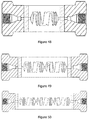
- FIG. 18 illustrates an exemplary embodiment of a static mixer assembly, according to some embodiments of the present disclosure.
- FIG. 19 a illustrates an exemplary embodiment of a static mixer, according to some embodiments of the present disclosure.
- FIG. 19 b illustrates an exemplary embodiment of a static mixer assembly, according to some embodiments of the present disclosure.
- FIG. 20 illustrates an exemplary embodiment of a static mixer assembly, according to some embodiments of the present disclosure.
- FIG. 21 illustrates an exemplary embodiment of a static mixer assembly, according to some embodiments of the present disclosure.
- FIG. 22 illustrates an exemplary graph of absorbance versus time, according to some embodiments of the present disclosure.
- FIG. 23 illustrates an exemplary embodiment of a mixer housing, according to some embodiments of the present disclosure.
- FIG. 24 illustrates an exemplary embodiment of a mixer housing, according to some embodiments of the present disclosure.
- FIG. 25 illustrates an exemplary embodiment of a static mixer, according to some embodiments of the present disclosure.
- FIG. 26 illustrates an exemplary embodiment of a static mixer assembly, according to some embodiments of the present disclosure.
- FIG. 27 illustrates an exemplary embodiment of a static mixer assembly, according to some embodiments of the present disclosure.
- FIG. 28 illustrates an exemplary embodiment of a static mixer assembly, according to some embodiments of the present disclosure.
- FIG. 29 illustrates an exemplary embodiment of a static mixer assembly, according to some embodiments of the present disclosure.
- FIG. 30 illustrates an exemplary embodiment of a static mixer assembly, according to some embodiments of the present disclosure.
- FIG. 31 illustrates an exemplary embodiment of a static mixer, according to some embodiments of the present disclosure.
- FIG. 32 illustrates an exemplary embodiment of a static mixer assembly, according to some embodiments of the present disclosure.
- FIG. 33 illustrates an exemplary embodiment of a static mixer assembly, according to some embodiments of the present disclosure.
- FIG. 34 illustrates an exemplary embodiment of a static mixer assembly, according to some embodiments of the present disclosure.
- FIG. 35 illustrates an exemplary embodiment of a static mixer, according to some embodiments of the present disclosure.
- FIG. 36 illustrates an exemplary embodiment of a static mixer assembly, according to some embodiments of the present disclosure.
- FIG. 37 illustrates an exemplary embodiment of a static mixer assembly, according to some embodiments of the present disclosure.
- FIG. 38 illustrates an exemplary embodiment of a static mixer assembly, according to some embodiments of the present disclosure.
- FIG. 39 illustrates an exemplary embodiment of a static mixer, according to some embodiments of the present disclosure.
- FIG. 40 illustrates an exemplary embodiment of a static mixer assembly, according to some embodiments of the present disclosure.
- FIG. 41 illustrates an exemplary embodiment of a static mixer assembly, according to some embodiments of the present disclosure.
- FIG. 42 illustrates an exemplary embodiment of a static mixer assembly, according to some embodiments of the present disclosure.
- FIG. 43 illustrates an exemplary embodiment of a static mixer, according to some embodiments of the present disclosure.
- FIG. 44 illustrates an exemplary embodiment of a static mixer assembly, according to some embodiments of the present disclosure.
- FIG. 45 illustrates an exemplary embodiment of a static mixer assembly, according to some embodiments of the present disclosure.
- FIG. 46 illustrates an exemplary embodiment of a static mixer assembly, according to some embodiments of the present disclosure.
- FIG. 47 illustrates an exemplary embodiment of a static mixer, according to some embodiments of the present disclosure.
- FIG. 48 illustrates an exemplary embodiment of a static mixer assembly, according to some embodiments of the present disclosure.
- FIG. 49 illustrates an exemplary embodiment of a static mixer assembly, according to some embodiments of the present disclosure.
- FIG. 50 illustrates an exemplary embodiment of a static mixer assembly, according to some embodiments of the present disclosure.
- FIG. 51 illustrates an exemplary embodiment of a static mixer, according to some embodiments of the present disclosure.
- FIG. 52 illustrates an exemplary embodiment of a static mixer assembly, according to some embodiments of the present disclosure.
- FIG. 53 illustrates an exemplary embodiment of a static mixer assembly, according to some embodiments of the present disclosure.
- FIG. 54 illustrates an exemplary embodiment of a static mixer assembly, according to some embodiments of the present disclosure.
- the present invention comprises various embodiments of a static mixer 100 that comprises a housing 110 with a proximal end 111 , a distal end 112 and an opening 115 extending between the proximal and distal ends, as shown in FIG. 1 .
- a plurality of metal frits 120 are positioned within the opening 115 , as shown in the cross-sectional view of static mixer 100 in FIG. 2 .
- the housings 110 used in the present invention are of any suitable size and shape. Although such housings are typically cylindrical and the openings therein are typically circular in cross-section (and are illustrated as such herein), they may be of any other suitable shape. Alternatively, the exterior of the housing 110 and the opening 115 may be of different cross-sectional shapes. In certain embodiments, the opening 115 is characterized by a substantially constant dimension along its full length, as illustrated in FIG. 2 . In certain embodiments, the opening 115 is circular in cross-section and has a substantially constant diameter of up to about 0.06′′. In certain embodiments, the opening 115 has a length of up to about 0.025′′.
- the opening 115 is characterized by more than one cross-sectional dimension and/or shapes along its length, as shown for exemplary embodiments herein.
- the opening 115 is circular in cross-section and has a diameter of up to about 0.06′′ in a first length, and a different diameter of up to about 0.03′′ in a second length.
- the cross-section of the opening is characterized by a first dimension at each of said proximal and distal ends, and a second dimension at a location between the proximal and distal ends, wherein the second dimension is less than said first dimension.
- the porous metal frits 120 of the present invention are characterized by an interconnected porosity.
- the pores within the metal frits of the present invention are preferably sized on the scale of micrometers, tens of micrometers, or hundreds of micrometers.
- the metal frits used in the present invention are characterized by nominal pore sizes that range from 0.2 to 100 micrometers, and more preferably 2 to 10 micrometers.
- the static mixers of the present invention comprise multiple metal frits in which each frit is characterized by a substantially similar nominal pore size.
- the static mixers of the present invention comprise multiple metal frits in which at least some of the frits are characterized by different nominal pore sizes.
- the metal frits are manufactured using suitable sintering techniques of metallic particles of suitable size and composition.
- the static mixers of the present invention make use of two, three, four or more metal frits 120 .
- the metal frits are optionally in direct contact with each adjacent frit, as illustrated in FIG. 2 .
- at least some of the metal frits may be spaced apart from any adjacent frit, such that a gap 310 is formed between frits as shown in FIG. 3 .
- gaps have a length of up to about 0.03′′.
- loose particulate is placed within one or more gaps formed between adjacent metal frits. Examples of suitable loose particulate material is in the form of metal particles having an average dimension of up to approximately 100 micrometers.
- Examples of embodiments of the present invention that make use of metal frits are described below.
- Examples 1-13 static mixer designs were based on utilizing a center cylindrical housing (0.25′′ OD, 0.062′′ ID ⁇ 0.25′′ long) into which porous metal frits of various media grades were placed in various combinations. These cylindrical housings were then welded to standard HPLC compression fittings to be able to test mixing performance using an Agilent 1100 series HPLC system.
- 316L stainless steel media grade 2 i.e., having a nominal mean pore size of 2 micrometers
- the frits were then sinter bonded to the stainless steel sleeve, and HPLC compression fitting hardware was welded to the sleeve to make the static mixer assembly as shown in FIG. 4 .
- the central housing is 316L stainless steel cylinder with and OD of 0.25′′, and ID of 0.062′′, and 0.025′′ long.
- the porous frits pressed into the housing were standard Mott media grade 2 frits with dimension of 0.062′′ diameter by 0.062′′ thick.
- the HPLC hardware welded to the housing were standard female (internal) stainless steel Zero Dead Volume 10-32 thread compression fittings for use with 1/16′′ OD tubing.
- the same external configuration was used as described in Example 1 with the only change being the media grade of the porous media inserted into the central housing.
- the porous metal frits from left to right were Mott Media Grade 2, Media Grade 10 (i.e., having a nominal mean pore size of 10 micrometers), Media Grade 2, and Media grade 10 all being of 316L stainless steel composition.
- the same external configuration was used as described in Example 1 with the only change being the media grade of the porous media inserted into the central housing.
- the porous metal frits from left to right were Mott Media Grade 2, Media Grade 2, Media Grade 10, and Media grade 10 all being of 316L stainless steel composition.
- Example 2 the same external configuration was used as described in Example 1 with the only change being the media grade of the porous media inserted into the central housing.
- all four of the inserted porous metal frits were Mott Media Grade 10, of 316L stainless steel composition.
- the porous frits pressed into the housing were standard Mott media grade 2 frits with dimension of 0.062′′ diameter by 0.062′′ thick and the gaps between the porous frits were 1/32′′ wide.
- the HPLC hardware welded to the housing were standard female (internal) stainless steel Zero Dead Volume 10-32 thread compression fittings for use with 1/16′′ OD tubing.
- the same external configuration was used as described in Example 5 with the only change being the media grade of the porous media inserted into the central housing.
- the porous metal frits from left to right were Mott Media Grade 2, Media Grade 10, and Media Grade 2 all being of 316L stainless steel composition.
- the same external configuration was used as described in Example 5 with the only change being the media grade of the porous media inserted into the central housing.
- the porous metal frits from left to right were Mott Media Grade 10, Media Grade 2, and Media Grade 10 all being of 316L stainless steel composition.
- Example 5 the same external configuration was used as described in Example 5 with the only change being the media grade of the porous media inserted into the central housing.
- all three of the inserted porous metal frits were Mott Media Grade 10, of 316L stainless steel composition.
- This example is a variation of Example 5 in which three 316L stainless steel media grade 2 porous metal frits were placed into a central sleeve housing containing two different diameters through its length as shown in FIG. 6 .
- the frits were sinter bonded to the stainless steel sleeve, and HPLC compression fitting hardware was welded to the sleeve to make the static mixer assembly.
- one smaller diameter frit is centered into the smaller diameter central housing section and the other two frits are placed in the larger diameter sections of the ends of housing cylinder. Mixing is enhanced by the gaps between the frits and the reduced diameter central region.
- the central housing is 316L stainless steel cylinder with and OD of 0.25′′, and ID's of 0.062′′ for the outer sections and 0.031′′ for the inner section.
- the porous frits pressed into the housing were standard Mott media grade 2 frits with dimension of 0.062′′ diameter by 0.062′′ thick for the outer sections and 0.031′′ diameter ⁇ 0.031′′ thick for the center section.
- the HPLC hardware welded to the housing were standard female (internal) stainless steel Zero Dead Volume 10-32 thread compression fittings for use with 1/16′′ OD tubing.
- the same external configuration was used as described in Example 9 with the only change being the media grade of the porous media inserted into the central housing.
- the porous metal frits from left to right were Mott Media Grade 2, Media Grade 10, and Media Grade 2 all being of 316L stainless steel composition.
- the same external configuration was used as described in Example 9 with the only change being the media grade of the porous media inserted into the central housing.
- the porous metal frits from left to right were Mott Media Grade 10, Media Grade 2, and Media Grade 10 all being of 316L stainless steel composition.
- Example 9 the same external configuration was used as described in Example 9 with the only change being the media grade of the porous media inserted into the central housing.
- all 3 of the inserted porous metal frits were Mott Media Grade 10, of 316L stainless steel composition.
- This example is similar to Example 9 in that a center section of the opening within the central sleeve housing has a reduced diameter relative to its end portions.
- loose metal particulate was placed within the central region of the opening in the housing, and two porous metal frits were inserted into the ends of a central sleeve housing, as shown in FIG. 7 .
- the frits are made from 316L stainless steel and are media grade 2.
- the central housing was a 316L stainless steel cylinder with an OD of 0.25′′, an ID of 0.031′′ and a length of 0.75′′.
- Cavities of 0.062′′ diameter and 0.062′′ deep were machined at each end of the central housing to expand the diameter of the opening within the housing at its ends, and to create areas in which to insert the porous metal frits.
- the porous frits pressed into the housing were standard Mott media grade 2 frits with dimension of 0.062′′ diameter by 0.062′′ thick.
- the metal powder placed into the center section was irregularly shaped 316L stainless steel with average dimensions of roughly 100 micrometers. In other embodiments, spherical metal powder can be used.
- the HPLC hardware welded to the housing were standard female (internal) stainless steel Zero Dead Volume 10-32 thread compression fittings for use with 1/16′′ OD tubing.
- static mixer elements are fabricated using laser additive manufacturing technology (“LAMT”).
- LAMT laser additive manufacturing technology
- additive manufacturing refers to a 3D printing process whereby successive layers of material are formed to create an object of a desired shape.
- Laser additive manufacturing or LAMT refers to additive manufacturing techniques that employ a laser to melt, soften, sinter or otherwise affect the material used in the object being manufactured. By varying material and manufacturing process specifications and conditions, a desired and tailored pore size, morphology and distribution can be produced.
- the resultant porous structure may be used as is, or it may be joined or otherwise fabricated with a solid full density component to complete a finished product.
- the type of laser additive manufacturing used in the present invention is any applicable technique, such as selective laser melting, selective laser sintering, and direct metal laser sintering.
- selective laser melting results in the complete or near-complete melting of particles using a high-energy laser; whereas selective laser sintering and direct metal laser sintering results in the sintering of particulate material, binding the material together to form a structure.
- laser additive manufacturing techniques that result in the sintering of particles are preferred over those that result in the melting of particles because melting techniques can result in a less porous structure than those preferred for use in the present invention.
- the lasers used in the present invention include any suitable lasers, such as carbon dioxide pulsed.
- the laser scans across the surface of a first layer of a particle bed placed onto a build plate (i.e., an underlying support structure of any suitable size, shape and composition) to melt or sinter the particles, followed by the application of another layer of particles for subsequent laser scanning and melting or sintering.
- a build plate i.e., an underlying support structure of any suitable size, shape and composition
- Multiple subsequent layers are created as the laser scans across the bed and layers of particulate are applied as necessary to create a product with a desired size and shape, often in accordance with CAD data corresponding to a 3D description of the product.
- the product is optionally separated from the build plate to form a final product suitable for use, unless the build plate is intended to be an integral component of the final product.
- sinter refers to any process in which particles are joined together by heat without the complete melting of the particles.
- the build angle i.e., the angle at which the LAMT product is formed relative to the horizontal plane of the build plate
- the inventors have found that building layers of particulate material using LAMT techniques to form structures at no less than 30° relative to the build plate is sufficient to prevent deterioration within the LAMT structure.
- Exemplary embodiments of the present invention form LAMT structures at 30°, 45°, and 60° relative to the build plate.
- Forming the LAMT product at a build angle in contrast to forming the LAMT product at no build angle such that it is in contact with the build plate at all locations along its cross-section, has the advantageous result of reducing the portion of the LAMT manufactured product that remains in contact with (and possibly bonded to) the build plate after completion of the LAMT process.
- LAMT products that are printed at a build angle may therefore be easier to separate from underlying build plates, in the event that such separation is desired.
- Build angles less than 30° generally may not result in enough of a basis for subsequent layer deposition. With insufficient support from base layer(s) that may result from build angles less than 30°, the resulting porous components may lose product integrity across multiple build layers.
- the materials used in the present invention are any materials provided in particulate form that can be sintered, partially melted, or entirely melted by a laser used in laser additive manufacturing techniques.
- “particulate,” “particles,” and “powder” are used synonymously to mean particles that are sized on the order of millimeters, micrometers or nanometers, and have any suitable shape such as spherical, substantially spherical (e.g., having an aspect ratio greater than 0.6, 0.7 or 0.8) and irregular, and mixtures thereof.
- a preferred particle size range for use in the present invention is less than 10 to 500 micrometers.
- the particle surface edge(s) may be smooth, sharp, or a mixture thereof.
- Preferred materials for use in the present invention include materials such as, for example, nickel, cobalt, iron, copper, aluminum, palladium, titanium, tungsten, platinum, silver, gold, and alloys and oxides thereof including stainless steels and nickel-based steels such as Hastelloy® (Haynes Stellite Company, Kokomo, Ind.). Various polymer materials may also be used.
- the LAMT techniques as described herein can be used to manufacture static mixer elements with complex shapes that are highly effective yet small in shape.
- the small and unique complex shapes of the present invention that may be manufactured using LAMT yield complex fluid flow patterns that, when compared with conventional mixers, result in more thorough mixing over smaller internal volumes. The result is a smaller sized mixer that can be used for the thorough mixing of multiple fluids.
- the static mixers of the present invention are particularly well-suited for applications such as HPLC.
- Examples 14-31 were based on utilizing LAMT to create flow paths that induce turbulence and/or folding of the fluid to promote mixing at low flow rates as typically seen in HPLC/UPLC applications. These designs utilize impeller designs that induce clockwise and anti-clockwise rotation of the fluid to promote mixing.
- the cavities surrounding the internal impellers were either left open (i.e., void of porous material) or filled with porous media to promote micro-mixing. Cylindrical cavities were created at the inlet and outlet ends of each device for optional installation of Mott porous metal frits to be used for filtration and/or micro mixing.
- This example makes use of an internal fixed impeller design with four segments, as shown in FIGS. 8 and 9 .
- the first segment induces clockwise rotation, the second reverses direction to anti-clockwise, the third segment rotates clockwise, and the 4th segment rotates anti-clockwise.
- the impeller diameter was 1 ⁇ 8′′ and each flow reversal segment was 1 ⁇ 8′′ in length.
- the impeller was constructed into the center of a 1 ⁇ 2′′ OD solid cylinder and the ends caped with an orifice 0.062′′ diameter by 0.062′′ deep. Porous metal media of Mott Media Grade 2 was pressed into the end cavities. Welded to both ends of these mixing housings are standard HPLC interface fittings that can be customized to nearly any dimension and configuration.
- the completed central mixing housing has a total of four flow reversals.
- the HPLC hardware welded to the housing for this example were standard female (internal) stainless steel Zero Dead Volume 10-32 thread compression fittings with external 3 ⁇ 4′′ external hexagonal wrench surface for use with 1/16′′ OD tubing.
- the internal volume of this assembly is roughly 75 microliters with a total of 4 flow reversals for the assembly.
- Example 14 makes use of the same external configuration as described in Example 14 with the only change being the central region of the mixing housing.
- the number of flow reversals was doubled (in comparison to Example 14), keeping all other dimensions constant except for the overall length of the assembly.
- the internal volume is roughly 150 microliters with a total of 8 flow reversals for the assembly.
- This example makes use of the same external configuration as described in Example 14 with the only change being the central region of the mixing housing.
- the internal volume is roughly 225 microliters with a total of 12 flow reversals for the assembly.
- Example 14 we use the same configuration as Example 14 with the only change being to the internal cavities for the flow path.
- the internal cavities are completely filled with porous metal media with a mean pore size of around 2 micrometers to promote micro mixing.
- the internal volume is roughly 25 microliters with a total of 4 flow reversals for the assembly.
- Example 14 we use the same configuration as Example 14 with the only change being to the internal cavities for the flow path.
- the internal cavities are completely filled with porous metal media with a mean pore size of around 10 micrometers to promote micro mixing.
- the internal volume is roughly 30 microliters with a total of 4 flow reversals for the assembly.
- Example 15 we use the same configuration as Example 15 with the only change being to the internal cavities for the flow path.
- the internal cavities are completely filled with porous metal media with a mean pore size of around 2 micrometers to promote micro mixing.
- the internal volume is roughly 50 microliters with a total of 8 flow reversals for the assembly.
- Example 15 we use the same configuration as Example 15 with the only change being to the internal cavities for the flow path.
- the internal cavities are completely filled with porous metal media with a mean pore size of around 10 micrometers to promote micro mixing.
- the internal volume is roughly 30 microliters with a total of 8 flow reversals for the assembly.
- Example 16 we use the same configuration as Example 16 with the only change being to the internal cavities for the flow path.
- the internal cavities are completely filled with porous metal media with a mean pore size of around 2 micrometers to promote micro mixing.
- the internal volume is roughly 75 microliters with a total of 12 flow reversals for the assembly.
- Example 16 we use the same configuration as Example 16 with the only change being to the internal cavities for the flow path.
- the internal cavities are completely filled with porous metal media with a mean pore size of around 10 micrometers to promote micro mixing.
- the internal volume is roughly 90 microliters with a total of 12 flow reversals for the assembly.
- each flow reversal occurs every 1/16′′ doubling the number of flow reversals in the same sized package.
- the internal volume is roughly 40 microliters with a total of 8 flow reversals for the assembly.
- each flow reversal occurs every 1/16′′ doubling the number of flow reversals in the same sized package.
- the internal volume is roughly 80 microliters with a total of 16 flow reversals for the assembly.
- each flow reversal occurs every 1/16′′ doubling the number of flow reversals in the same sized package.
- the internal volume is roughly 160 microliters with a total of 24 flow reversals for the assembly.
- Example 14 we use the same external configuration as described in Example 14 with the only change being the diameter of the internal mixing impellers reduced to 1/16′′.
- the internal volume is roughly 20 microliters with a total of 4 flow reversals for the assembly.
- Example 15 we use the same external configuration as described in Example 15 with the only change being the diameter of the internal mixing impellers reduced to 1/16′′.
- the internal volume is roughly 40 microliters with a total of 8 flow reversals for the assembly.
- Example 16 we use the same external configuration as described in Example 16 with the only change being the diameter of the internal mixing impellers reduced to 1/16′′.
- the internal volume is roughly 60 microliters with a total of 12 flow reversals for the assembly.
- Example 14 we use the same external configuration as described in Example 14 with changes to the diameter of the internal impeller and number of flow reversals.
- the diameters of the internal mixing impellers were reduced to 1/16′′ and the flow reversal occurring every 1/16′′.
- the internal volume is roughly 15 microliters with a total of 8 flow reversals for the assembly.
- Example 15 we use the same external configuration as described in Example 15 with changes to the diameter of the internal impeller and number of flow reversals.
- the diameters of the internal mixing impellers were reduced to 1/16′′ and the flow reversal occurring every 1/16′′.
- the internal volume is roughly 30 microliters with a total of 16 flow reversals for the assembly.
- Examples 32-76 were specifically to address the mixing valve on most HPLC systems, which produce alternating slugs of fluid traveling down the tubing by varying the volume of each slug to achieve the desired mixing ratio of the solvents. Examples 32-76 create fluid flow paths of different lengths and then recombine these flow paths multiple times to thoroughly mix these slugs of fluid producing a homogenized mix of solvents. As shown in previous examples, cylindrical cavities were created at the inlet and outlet ends of each device for optional installation of porous metal frits to be used for filtration and/or micro mixing.
- Examples 32-46 utilize what the applicants refer to as diamond designs, which create flow paths that follow a variety of directions and lengths starting from one location and recombining at a downstream location of the mixing device.
- the flow path is split into four separate flow paths, each being about 0.010′′ to 0.060′′ in diameter, preferably 0.030′′ in diameter, and then combining back to the periphery of a disc-shaped volume near the exit end of the device.
- Each of the initial four flow paths make one sharp bend and each has a slightly different overall length, thus assisting in creating phase shifts in the mixing process.
- Within each of these initial four flow paths are two flow branches of similar diameters that also contain sharp bends and different flow lengths that connect to an adjacent flow paths of the mixing device.
- one, two, or three of these devices were placed in series into assemblies, with and without porous media for testing purposes.
- All materials used for the diamond mixer design were 316L Stainless steel and it should be noted that any alloys suitable for HPLC applications can be used such as Hastelloy and Titanium alloys may be used.
- FIG. 10 we have a center mixing housing that contains one diamond pattern mixer with 0.062′′ diameter by 0.062′′ long chambers on both sides that were intentionally left open.
- FIG. 10 a shows detail of the mixing element
- FIG. 10 b shows the use of this mixing element as part of an example static mixer assembly.
- Attached to the inlet and outlet sides of the mixing chamber we have HPLC interface adapters.
- the HPLC hardware attached to the housing for this example were standard female (internal) stainless steel Zero Dead Volume 10-32 thread compression fittings with external 3 ⁇ 4′′ external hexagonal wrench surface for use with 1/16′′ OD tubing.
- the internal volume of this assembly is roughly 30 microliters.
- Example 32 we have the same diamond type mixing device and hardware as in Example 32 with the exception of the cavities on either side of the diamond flow pattern.
- the internal volume of this assembly is roughly 25 microliters.
- Example 32 we have the same diamond type mixing device and hardware as in Example 32 with the exception of the cavities on either side of the diamond flow pattern.
- the internal volume of this assembly is roughly 25 microliters.
- Example 33 we have the same diamond type mixing device and hardware as in Example 33 with the exception of the diamond flow pattern.
- the flow channels with stainless steel with an average pore size of 2 micrometers for enhanced micro mixing.
- the internal volume of this assembly is roughly 20 microliters.
- Example 33 we have the same diamond type mixing device and hardware as in Example 33 with the exception of the diamond flow pattern.
- the flow channels with porous stainless steel with an average pore size of 10 micrometers for enhanced micro mixing.
- the internal volume of this assembly is roughly 20 microliters.
- HPLC interface adapters Attached to the inlet and outlet sides of the mixing chamber we have HPLC interface adapters.
- the HPLC hardware attached to the housing for this example were standard female (internal) stainless steel Zero Dead Volume 10-32 thread compression fittings with external 3 ⁇ 4′′ external hexagonal wrench surface for use with 1/16′′ OD tubing.
- the internal volume of this assembly is roughly 60 microliters.
- Example 37 we have the same diamond type mixing device and hardware as in Example 37 with the exception of the cavities on either side of the diamond flow pattern mixers.
- the internal volume of this assembly is roughly 55 microliters.
- Example 37 we have the same diamond type mixing device and hardware as in Example 37 with the exception of the cavities on either side of the diamond flow pattern mixers.
- the internal volume of this assembly is roughly 55 microliters.
- Example 38 we have the same diamond type mixing device and hardware as in Example 38 with the exception of the diamond flow pattern.
- the flow channel with porous stainless steel with an average pore size of 2 micrometers for enhanced micro mixing.
- the internal volume of this assembly is roughly 45 microliters.
- Example 38 we have the same diamond type mixing device and hardware as in Example 38 with the exception of the diamond flow pattern.
- the flow channels with porous stainless steel with an average pore size of 10 micrometers for enhanced micro mixing.
- the internal volume of this assembly is roughly 45 microliters.
- a center mixing housing that contains three diamond pattern mixers, as shown in FIG. 12 , with 0.062′′ diameter by 0.062′′ long chambers that were intentionally left open. Attached to the inlet and outlet sides of the mixing chamber we have HPLC interface adapters.
- the HPLC hardware attached to the housing for this example were standard female (internal) stainless steel Zero Dead Volume 10-32 thread compression fittings with external 3 ⁇ 4′′ external hexagonal wrench surface for use with 1/16′′ OD tubing. The internal volume of this assembly is roughly 90 microliters.
- Example 42 we have the same diamond type mixing device and hardware as in Example 42 with the exception of the cavities on either side of the diamond flow pattern mixers.
- the internal volume of this assembly is roughly 85 microliters.
- Example 42 we have the same diamond type mixing device and hardware as in Example 42 with the exception of the cavities on either side of the diamond flow pattern mixers.
- the internal volume of this assembly is roughly 85 microliters.
- Example 43 we have the same diamond type mixing device and hardware as in Example 43 with the exception of the diamond flow pattern.
- the flow channel with porous stainless steel with an average pore size of 2 micrometers for enhanced micro mixing.
- the internal volume of this assembly is roughly 75 microliters.
- Example 43 we have the same diamond type mixing device and hardware as in Example 43 with the exception of the diamond flow pattern.
- the flow channels with porous stainless steel with an average pore size of 10 micrometers for enhanced micro mixing.
- the internal volume of this assembly is roughly 75 microliters.
- Examples 47-61 use what the applicants refer to as a helical coil design for the mixing process.
- this design there are two coils: an outer coil with a clockwise rotation and an inner coil with an anti-clockwise rotation.
- the pitch on the inner and outer coils can be the same, different, or variable along the length of the mixer.
- the two coils overlap by a predetermined amount such as 10-90%, more preferably 10-75%, and more preferably 40-75% so that fluid transfer between the inner and outer coils occur inducing mixing. Because of the clockwise and anti-clockwise rotation of the coils, when the fluid makes contact from one coil to the other, motion between these fluids is nearly head-on, which increases the efficiency of the mixing process.
- Both the inner and outer coils are about 0.025′′ diameter and begin and terminate on opposing sides of small volume manifolds at each end of the mixing device.
- one, two, or three of these devices were placed in series into assemblies with and without porous media for testing purposes.
- All materials used for the helical coil design were 316L Stainless steel and it should be noted that any alloys suitable for HPLC applications can be used such as Hastelloy and Titanium alloys may be used.
- any such examples may optionally include an obstruction at the intersection of the inner and outer coils to induce further mixing.
- FIG. 13 shows detail of the coil pattern mixing element
- FIG. 13 b shows the use of this mixing element as part of an example static mixer assembly.
- Attached to the inlet and outlet sides of the mixing chamber we have HPLC interface adapters.
- the HPLC hardware attached to the housing for this example were standard female (internal) stainless steel Zero Dead Volume 10-32 thread compression fittings with external 3 ⁇ 4′′ external hexagonal wrench surface for use with 1/16′′ OD tubing.
- the internal volume of this assembly is roughly 30 microliters.
- Example 47 we have the same coil type mixing device and hardware as in Example 47 with the exception of the cavities on either side of the coil flow pattern.
- the internal volume of this assembly is roughly 25 microliters.
- Example 47 we have the same coil type mixing device and hardware as in Example 47 with the exception of the cavities on either side of the coil flow pattern.
- the internal volume of this assembly is roughly 25 microliters.
- Example 48 we have the same coil type mixing device and hardware as in Example 48 with the exception of the coil flow pattern.
- the flow channels with stainless steel with an average pore size of 2 micrometers for enhanced micro mixing.
- the internal volume of this assembly is roughly 20 microliters.
- HPLC interface adapters Attached to the inlet and outlet sides of the mixing chamber we have HPLC interface adapters.
- the HPLC hardware attached to the housing for this example were standard female (internal) stainless steel Zero Dead Volume 10-32 thread compression fittings with external 3 ⁇ 4′′ external hexagonal wrench surface for use with 1/16′′ OD tubing.
- the internal volume of this assembly is roughly 60 microliters.
- Example 52 we have the same coil type mixing device and hardware as in Example 52 with the exception of the cavities on either side of the coil flow pattern mixers.
- the internal volume of this assembly is roughly 55 microliters.
- Example 52 we have the same coil type mixing device and hardware as in Example 52 with the exception of the cavities on either side of the coil flow pattern mixers.
- the internal volume of this assembly is roughly 55 microliters.
- Example 52 we have the same coil type mixing device and hardware as in Example 52 with the exception of the coil flow pattern.
- the flow channel with porous stainless steel with an average pore size of 2 micrometers for enhanced micro mixing.
- the internal volume of this assembly is roughly 45 microliters.
- Example 53 we have the same coil type mixing device and hardware as in Example 53 with the exception of the coil flow pattern.
- the flow channels with porous stainless steel with an average pore size of 10 micrometers for enhanced micro mixing.
- the internal volume of this assembly is roughly 45 microliters.
- a center mixing housing that contains three coil pattern mixers, as shown in FIG. 15 , with 0.062′′ diameter by 0.062′′ long chambers that were intentionally left open. Attached to the inlet and outlet sides of the mixing chamber we have HPLC interface adapters.
- the HPLC hardware attached to the housing for this example were standard female (internal) stainless steel Zero Dead Volume 10-32 thread compression fittings with external 3 ⁇ 4′′ external hexagonal wrench surface for use with 1/16′′ OD tubing. The internal volume of this assembly is roughly 90 microliters.
- Example 57 we have the same coil type mixing device and hardware as in Example 57 with the exception of the cavities on either side of the coil flow pattern mixers.
- the internal volume of this assembly is roughly 85 microliters.
- Example 57 we have the same coil type mixing device and hardware as in Example 57 with the exception of the cavities on either side of the coil flow pattern mixers.
- the internal volume of this assembly is roughly 85 microliters.
- Example 58 we have the same coil type mixing device and hardware as in Example 58 with the exception of the coil flow pattern.
- the flow channel with porous stainless steel with an average pore size of 2 micrometers for enhanced micro mixing.
- the internal volume of this assembly is roughly 75 microliters.
- Example 58 we have the same coil type mixing device and hardware as in Example 58 with the exception of the coil flow pattern.
- the flow channels with porous stainless steel with an average pore size of 10 micrometers for enhanced micro mixing.
- the internal volume of this assembly is roughly 75 microliters.
- Examples 62-76 use what the applicants refer to as a cylindrical design for the mixing process.
- This design employs a cylinder with cones at each end with a short cylindrical flow path at the tip of each end.
- the cylindrical tips at each end of the device are the inlet and outlets for the fluid flow.
- a variety of shapes are formed through the cylinder perpendicular to the nominal flow direction, which shapes act to form obstructions that impede flow and create mixing. These shapes include squares, rectangles, triangles, circles, diamonds, stars and any other geometry desired.
- the size and spacing of some of the shapes are intentionally varied to make the flow rate across the device non-symmetrical, to assist in phase shifting of the fluid during the mixing process.
- the obstructions traveling through cylindrical-cone shape device are repeated with a 90-degree rotation of the cylinder so that flow occurs in two dimensions while flowing longitudinally through the device.
- the figures that correspond to Examples 62-76 are drawn for ease of illustration to depict the obstructions as void space, and to further depict open space as solid material.
- a thin plate with numerous holes parallel to the flow direction is inserted for additional mixing (like a sieve).
- the shapes of these holes can be round, square, and any desired geometries and are typically less than 0.020′′ in lateral dimensions.
- one, two, or three of these devices were placed in series into assemblies with and without porous media for testing purposes. All materials used for the cylinder mixer design were 316L Stainless steel and it should be noted that any alloys suitable for HPLC applications can be used such as Hastelloy and titanium alloys, as well as polymers and ceramics may be used.
- FIG. 16 we have a center mixing housing that contains one cylinder pattern mixer, as shown in FIG. 16 , with 0.062′′ diameter by 0.062′′ long chambers that were intentionally left open.
- FIGS. 16 a -16 c shows detail of the cylinder pattern mixing element
- FIG. 16 d shows the use of this mixing element as part of an example static mixer assembly.
- Attached to the inlet and outlet sides of the mixing chamber we have HPLC interface adapters.
- the HPLC hardware attached to the housing for this example were standard female (internal) stainless steel Zero Dead Volume 10-32 thread compression fittings with external 3 ⁇ 4′′ external hexagonal wrench surface for use with 1/16′′ OD tubing.
- the internal volume of this assembly is roughly 60 microliters.
- Example 62 we have the same cylinder type mixing device and hardware as in Example 62 with the exception of the cavities on either side of the cylinder flow pattern.
- the internal volume of this assembly is roughly 55 microliters.
- Example 62 we have the same cylinder type mixing device and hardware as in Example 62 with the exception of the cavities on either side of the cylinder flow pattern.
- the internal volume of this assembly is roughly 55 microliters.
- HPLC interface adapters Attached to the inlet and outlet sides of the mixing chamber we have HPLC interface adapters.
- the HPLC hardware attached to the housing for this example were standard female (internal) stainless steel Zero Dead Volume 10-32 thread compression fittings with external 3 ⁇ 4′′ external hexagonal wrench surface for use with 1/16′′ OD tubing.
- the internal volume of this assembly is roughly 120 microliters.
- Example 67 we have the same cylinder type mixing device and hardware as in Example 67 with the exception of the cavities on either side of the cylinder flow pattern mixers.
- the internal volume of this assembly is roughly 115 microliters.
- Example 67 we have the same cylinder type mixing device and hardware as in Example 67 with the exception of the cavities on either side of the cylinder flow pattern mixers.
- the internal volume of this assembly is roughly 115 microliters.
- Example 68 we have the same cylinder type mixing device and hardware as in Example 68 with the exception of the cylinder flow pattern.
- the internal volume of this assembly is roughly 110 microliters.
- Example 68 we have the same cylinder type mixing device and hardware as in Example 68 with the exception of the cylinder flow pattern.
- the internal volume of this assembly is roughly 110 microliters.
- HPLC interface adapters Attached to the inlet and outlet sides of the mixing chamber we have HPLC interface adapters.
- the HPLC hardware attached to the housing for this example were standard female (internal) stainless steel Zero Dead Volume 10-32 thread compression fittings with external 3 ⁇ 4′′ external hexagonal wrench surface for use with 1/16′′ OD tubing.
- the internal volume of this assembly is roughly 180 microliters.
- Example 72 we have the same cylinder type mixing device and hardware as in Example 72 with the exception of the cavities on either side of the cylinder flow pattern mixers.
- the internal volume of this assembly is roughly 175 microliters.
- Example 73 we have the same cylinder type mixing device and hardware as in Example 73 with the exception of the cylinder flow pattern.
- the internal volume of this assembly is roughly 165 microliters.
- Example 73 we have the same cylinder type mixing device and hardware as in Example 73 with the exception of the cylinder flow pattern.
- the internal volume of this assembly is roughly 165 microliters.
- static mixer elements of the present invention make use of what the applicants refer to as a prism design for the mixing process.
- This design makes use of thin plate with angled ends with cones attached on each end with a short cylindrical flow path at the tip of each end.
- the cylindrical tips at each end of the device are the inlet and outlets for the fluid flow.
- a variety of shapes are placed through the flat plat perpendicular to the nominal flow direction to impede flow and create mixing. These shapes include squares, rectangles, triangles, circles, diamonds, stars and any other geometry desired.
- the size and spacing of some of the shapes are intentionally varied to make the flow rate across the device not symmetrical to assist in phase shifting of the fluid during the mixing process.
- a thin grating with numerous holes parallel to the flow direction is inserted for additional mixing (like a sieve).
- the shapes of these holes can be round, square, and any desired geometries and are typically less than 0.020′′ in lateral dimensions.
- One, two, or three of these devices were placed in series into assemblies with and without porous media for testing purposes. All materials used for the prism mixer design were 316L Stainless steel and it should be noted that any alloys suitable for HPLC applications can be used such as Hastelloy and titanium alloys, as well as polymers and ceramics may be used. It should be appreciated that the figures that correspond to Examples 77-91 are drawn for ease of illustration to depict the obstructions as void space, and to further depict open space as solid material.
- This example comprises a center mixing housing that contains one prism pattern mixer, as shown in FIG. 19 , with 0.062′′ diameter by 0.062′′ long chambers that were intentionally left open.
- FIG. 19 a shows detail of the prism pattern mixing element
- FIG. 19 b shows the use of this mixing element as part of an example static mixer assembly. Attached to the inlet and outlet sides of the mixing chamber we have HPLC interface adapters.
- the HPLC hardware attached to the housing for this example were standard female (internal) stainless steel Zero Dead Volume 10-32 thread compression fittings with external 3 ⁇ 4′′ external hexagonal wrench surface for use with 1/16′′ OD tubing.
- the internal volume of this assembly is roughly 30 microliters.
- Example 76 we have the same prism type mixing device and hardware as in Example 76 with the exception of the cavities on either side of the prism flow pattern.
- the internal volume of this assembly is roughly 25 microliters.
- Example 77 we have the same prism type mixing device and hardware as in Example 77 with the exception of the cavities on either side of the prism flow pattern.
- the internal volume of this assembly is roughly 25 microliters.
- Example 78 we have the same prism type mixing device and hardware as in Example 78 with the exception of the prism flow pattern.
- the internal volume of this assembly is roughly 20 microliters.
- Example 78 we have the same prism type mixing device and hardware as in Example 78 with the exception of the prism flow pattern.
- the internal volume of this assembly is roughly 20 microliters.
- a center mixing housing that contains two prism pattern mixers, as shown in FIG. 20 , with 0.062′′ diameter by 0.062′′ long chambers that were intentionally left open. Attached to the inlet and outlet sides of the mixing chamber we have HPLC interface adapters.
- the HPLC hardware attached to the housing for this example were standard female (internal) stainless steel Zero Dead Volume 10-32 thread compression fittings with external 3 ⁇ 4′′ external hexagonal wrench surface for use with 1/16′′ OD tubing.
- the internal volume of this assembly is roughly 60 microliters.
- Example 82 we have the same prism type mixing device and hardware as in Example 82 with the exception of the cavities on either side of the prism flow pattern mixers.
- the internal volume of this assembly is roughly 55 microliters.
- Example 82 we have the same prism type mixing device and hardware as in Example 82 with the exception of the cavities on either side of the prism flow pattern mixers.
- the internal volume of this assembly is roughly 55 microliters.
- Example 83 we have the same prism type mixing device and hardware as in Example 83 with the exception of the prism flow pattern.
- the internal volume of this assembly is roughly 55 microliters.
- Example 83 we have the same prism type mixing device and hardware as in Example 83 with the exception of the prism flow pattern.
- the internal volume of this assembly is roughly 50 microliters.
- a center mixing housing that contains three prism pattern mixers, as shown in FIG. 21 , with 0.062′′ diameter by 0.062′′ long chambers that were intentionally left open. Attached to the inlet and outlet sides of the mixing chamber we have HPLC interface adapters.
- the HPLC hardware attached to the housing for this example were standard female (internal) stainless steel Zero Dead Volume 10-32 thread compression fittings with external 3 ⁇ 4′′ external hexagonal wrench surface for use with 1/16′′ OD tubing. The internal volume of this assembly is roughly 90 microliters.
- Example 87 we have the same prism type mixing device and hardware as in Example 87 with the exception of the cavities on either side of the prism flow pattern mixers.
- the internal volume of this assembly is roughly 85 microliters.
- Example 87 we have the same prism type mixing device and hardware as in Example 87 with the exception of the cavities on either side of the prism flow pattern mixers.
- the internal volume of this assembly is roughly 85 microliters.
- Example 88 we have the same prism type mixing device and hardware as in Example 88 with the exception of the prism flow pattern.
- the flow channel with porous stainless steel with an average pore size of 2 micrometers for enhanced micro mixing.
- the internal volume of this assembly is roughly 80 microliters.
- Example 88 we have the same prism type mixing device and hardware as in Example 88 with the exception of the prism flow pattern.
- the internal volume of this assembly is roughly 80 microliters.
- FIG. 25 A variation of the static mixers described in Examples 77-91 is generally shown in FIG. 25 and described in Examples 92-96.
- the flow paths are connected to each other by common manifolds and the inlet and outlet ends of the device.
- FIG. 25 and Examples 92-96 make use of four parallel flow paths (depicted as solid space in the figures), it should be appreciated that any suitable number of parallel flow paths may be used, such as two, three, four, five, six, seven, eight, nine, or ten or more.
- the shape of the void spaces described in FIG. 25 and Examples 92-96 is octagonal, it should be appreciated that any suitably shaped spaces may be employed, such as triangular, square, rectangular, or other regular or irregular polygon.
- the void spaces may be the same or differently shaped, and the obstructions therein may be the same or different from those used in other void spaces.
- the thickness of each flow path varies from 0.006 inches to 0.012 inches, and may be the same or different from each other. In some cases, these parallel flow paths can be fabricated all with the same thickness targeting 0.009′′ for a mixer with an internal volume of 50 micro liters if desired. In certain embodiments, the internal volume is roughly 40 micro liters.
- the thickness of the parallel flow plates could be reduced or one or more of the plates could be removed resulting in a mixing module with internal volumes approaching roughly 5 micro liters.
- the thickness of the parallel flow paths may be increased and/or additional parallel flow paths could be added providing internal volumes for this design to easily exceed 250 micro liters.
- static mixers can be fabricated using 1 or more of these mixing modules in series expanding the range of internal volumes for static mixers from 5 microliters (one module with reduced plate thickness and quantities) up to for example 1250 micro liters (six parallel flow paths, increased plate thickness, and five modules in series).
- the thickness of these individual flow paths may be as low at 0.001 inches and as high as 0.1 inches with preferred thickness ranging from about 0.006 inches through 0.012 inches for this design.
- the internal void spaces can be left open or filled with porous metal to improve micro mixing and to reduce the internal volume of the device.
- the 0.062 counter bores at the inlet and outlet ends can be filed with standard metal frits to act as filters to prevent debris in the fluid stream from entering or leaving the device.
- These inlet/outlet frits and porous media within the internal cavities can be any Mott media grade from 0.1 through 40 with preferred values being Mott standard grades or 2 or 10. Installation of inlet and/or outlet frits also can reduce the internal volume of the device and provide improved micro mixing.
- FIG. 26 we have a center mixing housing that contains one parallel plate prism pattern mixer with 0.062′′ diameter by 0.062′′ long chambers at both ends that were intentionally left open. Attached to the inlet and outlet sides of the mixing chamber we have HPLC interface adapters.
- the HPLC hardware attached to the housing for this example were standard female (internal) stainless steel Zero Dead Volume 10-32 thread compression fittings with external 3 ⁇ 4′′ external hexagonal wrench surface for use with 1/16′′ OD tubing.
- the internal volume of this assembly is roughly 40 micro liters.
- FIG. 27 we have a center mixing housing that contains two parallel plate prism pattern mixers in series with 0.062′′ diameter by 0.062′′ long chambers at both ends that were intentionally left open. Attached to the inlet and outlet sides of the mixing chamber we have HPLC interface adapters.
- the HPLC hardware attached to the housing for this example were standard female (internal) stainless steel Zero Dead Volume 10-32 thread compression fittings with external 3 ⁇ 4′′ external hexagonal wrench surface for use with 1/16′′ OD tubing.
- the internal volume of this assembly is roughly 40 micro liters.
- FIG. 28 we have a center mixing housing that contains three parallel plate prism pattern mixers in series with 0.062′′ diameter by 0.062′′ long chambers that were intentionally left open. Attached to the inlet and outlet sides of the mixing chambers at both ends we have HPLC interface adapters.
- the HPLC hardware attached to the housing for this example were standard female (internal) stainless steel Zero Dead Volume 10-32 thread compression fittings with external 3 ⁇ 4′′ external hexagonal wrench surface for use with 1/16′′ OD tubing.
- the internal volume of this assembly is roughly 120 micro liters.
- FIG. 29 we have a center mixing housing that contains four parallel plate prism pattern mixers in series with 0.062′′ diameter by 0.062′′ long chambers at both ends that were intentionally left open. Attached to the inlet and outlet sides of the mixing chamber we have HPLC interface adapters.
- the HPLC hardware attached to the housing for this example were standard female (internal) stainless steel Zero Dead Volume 10-32 thread compression fittings with external 3 ⁇ 4′′ external hexagonal wrench surface for use with 1/16′′ OD tubing.
- the internal volume of this assembly is roughly 160 micro liters.
- FIG. 30 we have a center mixing housing that contains five parallel plate prism pattern mixers in series with 0.062′′ diameter by 0.062′′ long chambers at both ends that were intentionally left open. Attached to the inlet and outlet sides of the mixing chamber we have HPLC interface adapters.
- the HPLC hardware attached to the housing for this example were standard female (internal) stainless steel Zero Dead Volume 10-32 thread compression fittings with external 3 ⁇ 4′′ external hexagonal wrench surface for use with 1/16′′ OD tubing.
- the internal volume of this assembly is roughly 200 micro liters.
- a variation of the static mixers described in Examples 62-76 were developed in which the center cylindrical section was removed, resulting in a diamond like overall shape as generally shown in FIG. 31 and described in Examples 97-99. This modification was made to ease manufacturing and to reduce internal volume.
- the obstructions traveling through cylindrical-cone shape device are repeated with a 90-degree rotation of the cylinder so that flow occurs in two dimensions while flowing longitudinally through the device.
- a thin plate with numerous holes parallel to the flow direction for additional mixing (like a sieve).
- the shapes of these holes can be round, square, and any desired geometries and are typically less than 0.020′′ in lateral dimensions.
- 1-3 of these devices were placed in series into assemblies with and without porous media for testing purposes.
- FIG. 32 we have a center mixing housing that contains one diamond pattern mixer with 0.062′′ diameter by 0.062′′ long chambers at both ends that were intentionally left open. Attached to the inlet and outlet sides of the mixing chamber we have HPLC interface adapters.
- the HPLC hardware attached to the housing for this example were standard female (internal) stainless steel Zero Dead Volume 10-32 thread compression fittings with external 3 ⁇ 4′′ external hexagonal wrench surface for use with 1/16′′ OD tubing.
- the internal volume of this assembly is roughly 45 micro liters.
- FIG. 33 we have a center mixing housing that contains two diamond pattern mixers in series with 0.062′′ diameter by 0.062′′ long chambers at both ends that were intentionally left open. Attached to the inlet and outlet sides of the mixing chamber we have HPLC interface adapters.
- the HPLC hardware attached to the housing for this example were standard female (internal) stainless steel Zero Dead Volume 10-32 thread compression fittings with external 3 ⁇ 4′′ external hexagonal wrench surface for use with 1/16′′ OD tubing.
- the internal volume of this assembly is roughly 90 micro liters.
- FIG. 34 we have a center mixing housing that contains three diamond pattern mixers in series with 0.062′′ diameter by 0.062′′ long chambers at both ends that were intentionally left open. Attached to the inlet and outlet sides of the mixing chamber we have HPLC interface adapters.
- the HPLC hardware attached to the housing for this example were standard female (internal) stainless steel Zero Dead Volume 10-32 thread compression fittings with external 3 ⁇ 4′′ external hexagonal wrench surface for use with 1/16′′ OD tubing.
- the internal volume of this assembly is roughly 135 micro liters.
- the center cylindrical section was removed resulting in a smaller cylindrical center section as generally shown in FIG. 35 and described in Examples 100-102.
- This change was made to aid in manufacturing and to reduce internal volume.
- FIG. 36 we have a center mixing housing that contains one diamond pattern mixer with 0.062′′ diameter by 0.062′′ long chambers at both ends that were intentionally left open. Attached to the inlet and outlet sides of the mixing chamber we have HPLC interface adapters.
- the HPLC hardware attached to the housing for this example were standard female (internal) stainless steel Zero Dead Volume 10-32 thread compression fittings with external 3 ⁇ 4′′ external hexagonal wrench surface for use with 1/16′′ OD tubing.
- the internal volume of this assembly is roughly 50 micro liters.
- FIG. 37 we have a center mixing housing that contains two diamond pattern mixers in series with 0.062′′ diameter by 0.062′′ long chambers at both ends that were intentionally left open. Attached to the inlet and outlet sides of the mixing chamber we have HPLC interface adapters.
- the HPLC hardware attached to the housing for this example were standard female (internal) stainless steel Zero Dead Volume 10-32 thread compression fittings with external 3 ⁇ 4′′ external hexagonal wrench surface for use with 1/16′′ OD tubing.
- the internal volume of this assembly is roughly 100 micro liters.
- FIG. 38 we have a center mixing housing that contains three diamond pattern mixers in series with 0.062′′ diameter by 0.062′′ long chambers at both ends that were intentionally left open. Attached to the inlet and outlet sides of the mixing chamber we have HPLC interface adapters.
- the HPLC hardware attached to the housing for this example were standard female (internal) stainless steel Zero Dead Volume 10-32 thread compression fittings with external 3 ⁇ 4′′ external hexagonal wrench surface for use with 1/16′′ OD tubing.
- the internal volume of this assembly is roughly 150 micro liters.
- FIG. 39 A variation of the static mixers described in Examples 77 through 91 is generally shown in FIG. 39 and described in Examples 103-105.
- the thickness of both flow plates is the same being 0.030′′ thick.
- the flow plates can have different thicknesses for enhanced mixing.
- the internal volume is roughly 50 micro liters. If one has the need to lower the internal volume, then the thickness of the flow plates could be reduced resulting in a mixing module with internal volumes approaching roughly 10 micro liters.
- the thickness of the flow plates may be increased and/or additional parallel flow plates could be added at different rotation angles providing internal volumes for this design to easily exceed 250 micro liters.
- static mixers can be fabricated using one or more of these mixing modules in series expanding the range of internal volumes for static mixers from 10 microliters (one module with reduced plate thickness and quantities) up to for example 1250 micro liters (four parallel flow paths, increased plate thickness, and five modules in series). All materials used for the crossed plate mixer design were either 316L stainless steel or titanium and it should be noted that any alloys suitable for HPLC applications can be used such as Hastelloy and titanium alloys, as well as polymers and ceramics may be used. It should be appreciated that the figures that correspond to Examples 103-105 are drawn for ease of illustration to depict the obstructions as void space, and to further depict open space as solid material.
- FIG. 40 we have a center mixing housing that contains one crossed pattern mixer with 0.062′′ diameter by 0.062′′ long chambers at both ends that were intentionally left open. Attached to the inlet and outlet sides of the mixing chamber we have HPLC interface adapters.
- the HPLC hardware attached to the housing for this example were standard female (internal) stainless steel Zero Dead Volume 10-32 thread compression fittings with external 3 ⁇ 4′′ external hexagonal wrench surface for use with 1/16′′ OD tubing.
- the internal volume of this assembly is roughly 50 micro liters.
- FIG. 41 we have a center mixing housing that contains two crossed pattern mixers in series with 0.062′′ diameter by 0.062′′ long chambers at both ends that were intentionally left open. Attached to the inlet and outlet sides of the mixing chamber we have HPLC interface adapters.
- the HPLC hardware attached to the housing for this example were standard female (internal) stainless steel Zero Dead Volume 10-32 thread compression fittings with external 3 ⁇ 4′′ external hexagonal wrench surface for use with 1/16′′ OD tubing.
- the internal volume of this assembly is roughly 100 micro liters.
- FIG. 42 we have a center mixing housing that contains three crossed pattern mixers in series with 0.062′′ diameter by 0.062′′ long chambers at both ends that were intentionally left open. Attached to the inlet and outlet sides of the mixing chamber we have HPLC interface adapters.
- the HPLC hardware attached to the housing for this example were standard female (internal) stainless steel Zero Dead Volume 10-32 thread compression fittings with external 3 ⁇ 4′′ external hexagonal wrench surface for use with 1/16′′ OD tubing.
- the internal volume of this assembly is roughly 150 micro liters.
- FIG. 43 A variation of the static mixers described in Examples 32-46 is generally shown in FIG. 43 .
- the flow paths basically follow the edges, faces and center of a cube resulting in a variety of flow path lengths to providing mixing when they recombine.
- the internal volume was roughly 45 micro liters.
- the diameter of the flow paths can be reduced down to about 0.005′′ resulting in an internal volume about 5 micro liters. If one desires larger volumes, the flow path diameters may be increased to about 0.1 inches giving a volume of about 250 micro liters.
- FIG. 44 we have a center mixing housing that contains one pattern mixer with 0.062′′ diameter by 0.062′′ long chambers at both ends that were intentionally left open. Attached to the inlet and outlet sides of the mixing chamber we have HPLC interface adapters.
- the HPLC hardware attached to the housing for this example were standard female (internal) stainless steel Zero Dead Volume 10-32 thread compression fittings with external 3 ⁇ 4′′ external hexagonal wrench surface for use with 1/16′′ OD tubing.
- the internal volume of this assembly is roughly 45 micro liters.
- FIG. 45 we have a center mixing housing that contains two pattern mixers in series with 0.062′′ diameter by 0.062′′ long chambers at both ends that were intentionally left open. Attached to the inlet and outlet sides of the mixing chamber we have HPLC interface adapters.
- the HPLC hardware attached to the housing for this example were standard female (internal) stainless steel Zero Dead Volume 10-32 thread compression fittings with external 3 ⁇ 4′′ external hexagonal wrench surface for use with 1/16′′ OD tubing.
- the internal volume of this assembly is roughly 90 micro liters.
- FIG. 46 we have a center mixing housing that contains three pattern mixers in series with 0.062′′ diameter by 0.062′′ long chambers at both ends that were intentionally left open. Attached to the inlet and outlet sides of the mixing chamber we have HPLC interface adapters.
- the HPLC hardware attached to the housing for this example were standard female (internal) stainless steel Zero Dead Volume 10-32 thread compression fittings with external 3 ⁇ 4′′ external hexagonal wrench surface for use with 1/16′′ OD tubing.
- the internal volume of this assembly is roughly 135 micro liters.
- the static mixers of the present invention use tilted disc flow paths connected at 90 degree intervals along the length of the device, as generally shown in FIG. 47 .
- the internal volume was roughly 40 micro liters.
- the diameter and thickness of the flow paths can be reduced down to about 0.005′′ thick and 0.1′′ diameter resulting in an internal volume about 5 micro liters. If one desires larger volumes, the flow path the thickness and diameters may be increased to achieve volumes approaching 250 micro liters.
- 1-3 of these devices were placed in series into assemblies with and without porous media for testing purposes. If larger volumes are needed, one can simply add more modules in series to attain larger volumes such as 2000 micro liters if desired. All materials used for this mixer design were either 316L stainless steel or titanium and it should be noted that any alloys suitable for HPLC applications can be used such as Hastelloy and titanium alloys, as well as polymers and ceramics may be used.
- FIG. 48 we have a center mixing housing that contains one tilted disc pattern mixer with 0.062′′ diameter by 0.062′′ long chambers at both ends that were intentionally left open. Attached to the inlet and outlet sides of the mixing chamber we have HPLC interface adapters.
- the HPLC hardware attached to the housing for this example were standard female (internal) stainless steel Zero Dead Volume 10-32 thread compression fittings with external 3 ⁇ 4′′ external hexagonal wrench surface for use with 1/16′′ OD tubing.
- the internal volume of this assembly is roughly 40 micro liters.
- FIG. 49 we have a center mixing housing that contains two tilted disc pattern mixers in series with 0.062′′ diameter by 0.062′′ long chambers at both ends that were intentionally left open. Attached to the inlet and outlet sides of the mixing chamber we have HPLC interface adapters.
- the HPLC hardware attached to the housing for this example were standard female (internal) stainless steel Zero Dead Volume 10-32 thread compression fittings with external 3 ⁇ 4′′ external hexagonal wrench surface for use with 1/16′′ OD tubing.
- the internal volume of this assembly is roughly 80 micro liters.
- FIG. 50 we have a center mixing housing that contains three tilted disc pattern mixers in series with 0.062′′ diameter by 0.062′′ long chambers at both ends that were intentionally left open. Attached to the inlet and outlet sides of the mixing chamber we have HPLC interface adapters.
- the HPLC hardware attached to the housing for this example were standard female (internal) stainless steel Zero Dead Volume 10-32 thread compression fittings with external 3 ⁇ 4′′ external hexagonal wrench surface for use with 1/16′′ OD tubing.
- the internal volume of this assembly is roughly 120 micro liters.
- FIG. 51 A variation of the static mixers described in Examples 47-61 is generally shown in FIG. 51 and referred to as a double helix coil design for the mixing process.
- the pitch on the inner and outer coils can be the same, different, or variable along the length of the mixer.
- the two coils overlap by up to 100% so that fluid transfer between the inner and outer coils occur inducing mixing. Because of the clockwise and anti-clockwise rotation of the coils, when the fluid makes contact from one coil to the other, motion is nearly head on which increases the efficiency of the mixing process.
- both coils have flow paths of 0.030 inch diameter wound to a 0.25 inch diameter and begin and terminate on opposing sides of small volume manifolds at each end of the mixing device.
- the internal volume was 40 micro liters.
- 1-3 of these devices were placed in series into assemblies with and without porous media for testing purposes.
- the diameter of the flow paths may be decreased down to about 0.005 inches or increased to about 0.040 inches to reduce or increase the internal volume of the device.
- the pitch of the windings can be adjusted again to control the internal volume.
- the range in volume for this design can vary from 10 micro liters up to 200 micro liters for a single module.
- FIG. 52 we have a center mixing housing that contains one double helix pattern mixer with 0.062′′ diameter by 0.062′′ long chambers at both ends that were intentionally left open. Attached to the inlet and outlet sides of the mixing chamber we have HPLC interface adapters.
- the HPLC hardware attached to the housing for this example were standard female (internal) stainless steel Zero Dead Volume 10-32 thread compression fittings with external 3 ⁇ 4′′ external hexagonal wrench surface for use with 1/16′′ OD tubing.
- the internal volume of this assembly is roughly 40 micro liters.
- FIG. 53 we have a center mixing housing that contains two double helix pattern mixers in series with 0.062′′ diameter by 0.062′′ long chambers at both ends that were intentionally left open. Attached to the inlet and outlet sides of the mixing chamber we have HPLC interface adapters.
- the HPLC hardware attached to the housing for this example were standard female (internal) stainless steel Zero Dead Volume 10-32 thread compression fittings with external 3 ⁇ 4′′ external hexagonal wrench surface for use with 1/16′′ OD tubing.
- the internal volume of this assembly is roughly 80 micro liters.
- FIG. 54 we have a center mixing housing that contains three double helix pattern mixers in series with 0.062′′ diameter by 0.062′′ long chambers at both ends that were intentionally left open. Attached to the inlet and outlet sides of the mixing chamber we have HPLC interface adapters.
- the HPLC hardware attached to the housing for this example were standard female (internal) stainless steel Zero Dead Volume 10-32 thread compression fittings with external 3 ⁇ 4′′ external hexagonal wrench surface for use with 1/16′′ OD tubing.
- the internal volume of this assembly is roughly 120 micro liters.
- the absorption of light was measured through solvent mixtures mixed with various static mixers, including Examples of the present invention and several commercially available mixers.
- the absorption is expressed in milli-absorption units or “mAU.”
- mAU milli-absorption units
- the absorption over time is sinusoidal in nature when inadequate mixing is present, and is referred to as a ripple having an amplitude.
- a lower amplitude reflects a solvent mixture that is more homogeneously mixed, and would therefore result in a less noisy signal in an HPLC application.
- the internal volume of each mixer was measured. Generally, mixers with higher internal volumes are able to more thoroughly mix solvents but degrade peak shape and resolution.
- the most preferred mixers have low ripple amplitudes (or in other words, high reduction percentages in ripple amplitudes compared with HPLC environments that do not include a mixer), and low volumes.
- ripple amplitudes or in other words, high reduction percentages in ripple amplitudes compared with HPLC environments that do not include a mixer
- the present invention comprises a housing with multiple openings having different diameters from each other, with each opening extending through the housing either with a constant diameter or with one or more of the openings having a varying diameter.
- the different diameter opening result in different fluid flow rates through the openings, thus resulting in the mixing fluids after movement through the mixer.
- FIG. 23 shows that there are five parallel openings through a single housing, with each passage having a different diameter.
- the diameters of the openings range from 0.015′′ to 0.078′′, although it should be appreciated that any suitable diameters would be applicable to the present invention.
- the difference in the diameters results in a difference in the internal volume of each flow passage such that when fluids recombine after moving through the mixer, phase mixing occurs.
- FIG. 24 there are also five through openings, but here, four of the openings have varying diameters as can be seen in FIG. 24 c .
- the central passage has a constant diameter of about 0.03′′ whereas the other passages start with a larger diameter of about 0.06′′ and transition to smaller diameters at different points along their lengths. It should be appreciated that other suitable diameters are also useful in the present invention.
- the transition to smaller diameters can be gradual or step-wise, as shown in FIG. 24 c .
- the openings may be left fully open or filled with porous media at one or both ends, or throughout, to reduce the total internal volume and to aid in micro mixing.
- the current embodiments are described and illustrated as having five openings, it should be noted that the number of openings can be fewer or more to impact mixing characteristics.
- these embodiments may be used in conjunction with HPLC hardware as described herein for other the embodiments and Examples.
- fluids to be mixed by the mixers of the present invention come from two different flow sources, which may require mixer assemblies that include two or more standard HPLC connections on the inlet side of the mixer assembly to combine the fluids prior to entering the mixing portion of the device.
- mixer assemblies described herein can be used as stand-alone, singular devices, or as multiple units plumbed in series to provide additional levels of mixing.
- mixer assemblies can be fabricated with male and female HPLC compression fittings to make it more convenient to connect multiple mixers together while at the same time minimizing their linear footprint where space is a concern.
Landscapes
- Chemical & Material Sciences (AREA)
- Chemical Kinetics & Catalysis (AREA)
- Dispersion Chemistry (AREA)
- Analytical Chemistry (AREA)
- Immunology (AREA)
- Physics & Mathematics (AREA)
- Health & Medical Sciences (AREA)
- Life Sciences & Earth Sciences (AREA)
- Biochemistry (AREA)
- General Health & Medical Sciences (AREA)
- General Physics & Mathematics (AREA)
- Pathology (AREA)
- Materials Engineering (AREA)
- Manufacturing & Machinery (AREA)
- Engineering & Computer Science (AREA)
- Processing And Handling Of Plastics And Other Materials For Molding In General (AREA)
Priority Applications (1)
| Application Number | Priority Date | Filing Date | Title |
|---|---|---|---|
| US15/663,741 US10661237B2 (en) | 2016-08-29 | 2017-07-29 | High performance static mixer |
Applications Claiming Priority (2)
| Application Number | Priority Date | Filing Date | Title |
|---|---|---|---|
| US201662380688P | 2016-08-29 | 2016-08-29 | |
| US15/663,741 US10661237B2 (en) | 2016-08-29 | 2017-07-29 | High performance static mixer |
Publications (2)
| Publication Number | Publication Date |
|---|---|
| US20180056252A1 US20180056252A1 (en) | 2018-03-01 |
| US10661237B2 true US10661237B2 (en) | 2020-05-26 |
Family
ID=59593178
Family Applications (1)
| Application Number | Title | Priority Date | Filing Date |
|---|---|---|---|
| US15/663,741 Expired - Fee Related US10661237B2 (en) | 2016-08-29 | 2017-07-29 | High performance static mixer |
Country Status (7)
| Country | Link |
|---|---|
| US (1) | US10661237B2 (fr) |
| EP (1) | EP3503985B1 (fr) |
| ES (1) | ES2934701T3 (fr) |
| FI (1) | FI3503985T3 (fr) |
| MA (1) | MA46132A (fr) |
| PL (1) | PL3503985T3 (fr) |
| WO (1) | WO2018044451A1 (fr) |
Families Citing this family (16)
| Publication number | Priority date | Publication date | Assignee | Title |
|---|---|---|---|---|
| US11185830B2 (en) | 2017-09-06 | 2021-11-30 | Waters Technologies Corporation | Fluid mixer |
| US11577440B2 (en) | 2018-07-09 | 2023-02-14 | Material Answers Llc | Methods for generating interfacial surfaces and devices therefor |
| WO2020012369A2 (fr) * | 2018-07-10 | 2020-01-16 | Precision Planting Llc | Système d'échantillonnage agricole et procédés associés |
| GB201817692D0 (en) * | 2018-10-30 | 2018-12-19 | Ge Healthcare | Mixing device |
| AT16307U3 (de) * | 2018-11-19 | 2019-12-15 | Plansee Se | Additiv gefertigtes Refraktärmetallbauteil, additives Fertigungsverfahren und Pulver |
| US11555805B2 (en) | 2019-08-12 | 2023-01-17 | Waters Technologies Corporation | Mixer for chromatography system |
| WO2022010665A1 (fr) | 2020-07-07 | 2022-01-13 | Waters Technologies Corporation | Mélangeur pour chromatographie en phase liquide |
| CN115812146A (zh) | 2020-07-07 | 2023-03-17 | 沃特世科技公司 | 用于流体色谱法降噪的组合式混合器装置 |
| BR112023001168A2 (pt) * | 2020-08-06 | 2023-02-28 | Regeneron Pharma | Misturador em escala reduzida |
| WO2022066752A1 (fr) | 2020-09-22 | 2022-03-31 | Waters Technologies Corporation | Mélangeur à écoulement continu |
| JP2023549027A (ja) * | 2020-11-12 | 2023-11-22 | モット・コーポレーション | 静的ミキサーアセンブリ、並びに関連する製造及び使用方法 |
| SE545007C2 (en) * | 2021-01-18 | 2023-02-28 | Valmet Oy | Mixing device and method for mixing a fluid into a fiber pulp |
| CN117355747A (zh) * | 2021-05-20 | 2024-01-05 | 沃特世科技公司 | 等分散分流混合器 |
| EP4359118A1 (fr) | 2021-06-23 | 2024-05-01 | Waters Technologies Corporation | Mélangeur de solvant passif pour chromatographie en phase liquide |
| CN113477480B (zh) * | 2021-06-30 | 2022-06-14 | 深圳市南极光电子科技股份有限公司 | 一种MiniLED模组的制造设备及制造工艺 |
| CN119215713B (zh) * | 2024-12-02 | 2025-01-28 | 武汉理工大学三亚科教创新园 | 一种油水乳化的静态混合器 |
Citations (11)
| Publication number | Priority date | Publication date | Assignee | Title |
|---|---|---|---|---|
| US3453811A (en) * | 1968-05-03 | 1969-07-08 | Abcor Inc | Chromatographic columns with partition elements therein |
| US4582608A (en) * | 1985-02-15 | 1986-04-15 | Separations Technology, Inc. | HPLC column |
| US6637928B2 (en) | 2000-12-20 | 2003-10-28 | Bayer Aktiengesellschaft | Static mixer |
| US7325970B2 (en) | 2002-12-06 | 2008-02-05 | Sulzer Mixpac Ag | Static mixer |
| US7588683B2 (en) * | 2005-08-03 | 2009-09-15 | Agilent Technologies, Inc. | Column for liquid chromatography with adjustable compression |
| US20110049030A1 (en) | 2009-09-02 | 2011-03-03 | Agilent Technologies, Inc. | Chromatography Column With Large Diameter End Fitting Openings |
| GB2506165A (en) | 2012-09-24 | 2014-03-26 | Thermo Electron Mfg Ltd | Chromatography column |
| US8776621B2 (en) * | 2009-03-06 | 2014-07-15 | Dionex Corporation | Fluid sample delivery system and method |
| US20150219604A1 (en) * | 2012-09-24 | 2015-08-06 | Thermo Electron Manufacturing Limited | Chromatography columns |
| US9290372B2 (en) * | 2010-06-15 | 2016-03-22 | Ge Healthcare Bio-Sciences Ab | Fluid distributor unit |
| US20160175787A1 (en) * | 2014-12-18 | 2016-06-23 | The Procter & Gamble Company | Static mixer |
Family Cites Families (3)
| Publication number | Priority date | Publication date | Assignee | Title |
|---|---|---|---|---|
| US6696022B1 (en) * | 1999-08-13 | 2004-02-24 | U.S. Genomics, Inc. | Methods and apparatuses for stretching polymers |
| DE19959249A1 (de) * | 1999-12-08 | 2001-07-19 | Inst Mikrotechnik Mainz Gmbh | Modulares Mikroreaktionssystem |
| MY155726A (en) * | 2011-11-01 | 2015-11-17 | Mimos Berhad | A microfluidic system and method thereof |
-
2017
- 2017-07-29 FI FIEP17751899.0T patent/FI3503985T3/fi active
- 2017-07-29 WO PCT/US2017/044562 patent/WO2018044451A1/fr not_active Ceased
- 2017-07-29 ES ES17751899T patent/ES2934701T3/es active Active
- 2017-07-29 US US15/663,741 patent/US10661237B2/en not_active Expired - Fee Related
- 2017-07-29 MA MA046132A patent/MA46132A/fr unknown
- 2017-07-29 PL PL17751899.0T patent/PL3503985T3/pl unknown
- 2017-07-29 EP EP17751899.0A patent/EP3503985B1/fr active Active
Patent Citations (12)
| Publication number | Priority date | Publication date | Assignee | Title |
|---|---|---|---|---|
| US3453811A (en) * | 1968-05-03 | 1969-07-08 | Abcor Inc | Chromatographic columns with partition elements therein |
| US4582608A (en) * | 1985-02-15 | 1986-04-15 | Separations Technology, Inc. | HPLC column |
| US6637928B2 (en) | 2000-12-20 | 2003-10-28 | Bayer Aktiengesellschaft | Static mixer |
| US7325970B2 (en) | 2002-12-06 | 2008-02-05 | Sulzer Mixpac Ag | Static mixer |
| US7588683B2 (en) * | 2005-08-03 | 2009-09-15 | Agilent Technologies, Inc. | Column for liquid chromatography with adjustable compression |
| US8776621B2 (en) * | 2009-03-06 | 2014-07-15 | Dionex Corporation | Fluid sample delivery system and method |
| US20110049030A1 (en) | 2009-09-02 | 2011-03-03 | Agilent Technologies, Inc. | Chromatography Column With Large Diameter End Fitting Openings |
| US8936723B2 (en) * | 2009-09-02 | 2015-01-20 | Agilent Technologies, Inc. | Chromatography column with large diameter end fitting openings |
| US9290372B2 (en) * | 2010-06-15 | 2016-03-22 | Ge Healthcare Bio-Sciences Ab | Fluid distributor unit |
| GB2506165A (en) | 2012-09-24 | 2014-03-26 | Thermo Electron Mfg Ltd | Chromatography column |
| US20150219604A1 (en) * | 2012-09-24 | 2015-08-06 | Thermo Electron Manufacturing Limited | Chromatography columns |
| US20160175787A1 (en) * | 2014-12-18 | 2016-06-23 | The Procter & Gamble Company | Static mixer |
Non-Patent Citations (1)
| Title |
|---|
| International Search Report and Written Opinion of PCT/US2017/044562, dated Jan. 9, 2018, 18 pages. |
Also Published As
| Publication number | Publication date |
|---|---|
| EP3503985A1 (fr) | 2019-07-03 |
| EP3503985B1 (fr) | 2022-09-28 |
| FI3503985T3 (fi) | 2023-01-13 |
| US20180056252A1 (en) | 2018-03-01 |
| WO2018044451A1 (fr) | 2018-03-08 |
| ES2934701T3 (es) | 2023-02-24 |
| PL3503985T3 (pl) | 2023-05-29 |
| MA46132A (fr) | 2019-07-03 |
Similar Documents
| Publication | Publication Date | Title |
|---|---|---|
| US10661237B2 (en) | High performance static mixer | |
| JP3578355B2 (ja) | 混合装置 | |
| US8414182B2 (en) | Micromixers for nanomaterial production | |
| EP2017000B1 (fr) | Dispositifs microfluidiques pour procédés intensifiés | |
| JP6815989B2 (ja) | 乱流促進手段を内蔵したタンジェンシャルフロー分離用多流路管状エレメントの新規な形状及びその製造方法 | |
| KR102471175B1 (ko) | 굴곡성 채널을 갖춘 접선유동 세퍼레이터 요소 | |
| ES2885430T3 (es) | Nuevas geometrías de elementos tubulares monocanales de separación por flujo tangencial que integran unos promotores de turbulencias y procedimiento de fabricación | |
| JP2002224549A (ja) | 静的混合機 | |
| JP2020529309A (ja) | 改善されたプロセス強化フローリアクタ | |
| US20210231543A1 (en) | Microscale and mesoscale condenser devices | |
| JP6509330B2 (ja) | 微細構造分離フィルタ | |
| JPH04503919A (ja) | 容器のパッキング | |
| JP2017523915A (ja) | 流れ障害物を内蔵したタンジェンシャルフロー分離用エレメント及びその製造方法 | |
| JP2008264640A (ja) | 混合器 | |
| CN108325483B (zh) | 微孔涡流套管反应器及其应用 | |
| JP2024517670A (ja) | 流体を混合して混合流体を調製する装置および方法 | |
| US10857508B2 (en) | Continuous micro mixer | |
| JPS62269733A (ja) | 混合素子及び該混合素子を内蔵した混合装置 | |
| EP4179311B1 (fr) | Agencement de mélangeur combiné pour la réduction de bruit en chromatographie en phase fluide | |
| JP4627302B2 (ja) | 微粒子の製造方法及び装置 | |
| US20230415107A1 (en) | Static mixer assemblies and related methods of fabrication and use | |
| JP2022506201A (ja) | 混合デバイス | |
| EP1776183A1 (fr) | Dispositif et procede pour mettre en oeuvre en continu des processus chimiques | |
| DE19638794C1 (de) | Wärmetauscher | |
| JP2003010663A (ja) | 物質の微粒化装置 |
Legal Events
| Date | Code | Title | Description |
|---|---|---|---|
| AS | Assignment |
Owner name: MOTT CORPORATION, CONNECTICUT Free format text: ASSIGNMENT OF ASSIGNORS INTEREST;ASSIGNORS:STEELE, JAMES K.;MARTINO, CHRISTOPHER;SIOK, MATTHEW C.;AND OTHERS;REEL/FRAME:043844/0422 Effective date: 20161010 |
|
| AS | Assignment |
Owner name: WEBSTER BANK, NATIONAL ASSOCIATION, CONNECTICUT Free format text: SECURITY INTEREST;ASSIGNOR:MOTT CORPORATION;REEL/FRAME:045323/0761 Effective date: 20180322 |
|
| STPP | Information on status: patent application and granting procedure in general |
Free format text: NON FINAL ACTION MAILED |
|
| STPP | Information on status: patent application and granting procedure in general |
Free format text: RESPONSE TO NON-FINAL OFFICE ACTION ENTERED AND FORWARDED TO EXAMINER |
|
| STPP | Information on status: patent application and granting procedure in general |
Free format text: FINAL REJECTION MAILED |
|
| STPP | Information on status: patent application and granting procedure in general |
Free format text: DOCKETED NEW CASE - READY FOR EXAMINATION |
|
| STPP | Information on status: patent application and granting procedure in general |
Free format text: NOTICE OF ALLOWANCE MAILED -- APPLICATION RECEIVED IN OFFICE OF PUBLICATIONS |
|
| ZAAA | Notice of allowance and fees due |
Free format text: ORIGINAL CODE: NOA |
|
| ZAAB | Notice of allowance mailed |
Free format text: ORIGINAL CODE: MN/=. |
|
| STPP | Information on status: patent application and granting procedure in general |
Free format text: PUBLICATIONS -- ISSUE FEE PAYMENT VERIFIED |
|
| STCF | Information on status: patent grant |
Free format text: PATENTED CASE |
|
| AS | Assignment |
Owner name: PNC BANK, NATIONAL ASSOCIATION, AS ADMINISTRATIVE AGENT, CONNECTICUT Free format text: SECURITY INTEREST;ASSIGNOR:MOTT CORPORATION;REEL/FRAME:062695/0152 Effective date: 20230214 |
|
| AS | Assignment |
Owner name: MOTT CORPORATION, CONNECTICUT Free format text: RELEASE BY SECURED PARTY;ASSIGNOR:WEBSTER BANK, NATIONAL ASSOCIATION;REEL/FRAME:062712/0613 Effective date: 20230214 |
|
| FEPP | Fee payment procedure |
Free format text: MAINTENANCE FEE REMINDER MAILED (ORIGINAL EVENT CODE: REM.); ENTITY STATUS OF PATENT OWNER: SMALL ENTITY |
|
| AS | Assignment |
Owner name: PNC BANK, NATIONAL ASSOCIATION, AS ADMINISTRATIVE AGENT, CONNECTICUT Free format text: SECURITY INTEREST;ASSIGNORS:MOTT CORPORATION;DIGESTED ORGANICS LLC;REEL/FRAME:067162/0539 Effective date: 20240418 |
|
| STCH | Information on status: patent discontinuation |
Free format text: PATENT EXPIRED DUE TO NONPAYMENT OF MAINTENANCE FEES UNDER 37 CFR 1.362 |
|
| FP | Lapsed due to failure to pay maintenance fee |
Effective date: 20240526 |
|
| AS | Assignment |
Owner name: MOTT CORPORATION, CONNECTICUT Free format text: SECURITY INTEREST;ASSIGNOR:PNC BANK, NATIONAL ASSOCIATION, AS ADMINISTRATIVE AGENT;REEL/FRAME:072559/0785 Effective date: 20251001 Owner name: DIGESTED ORGANICS LLC, CONNECTICUT Free format text: SECURITY INTEREST;ASSIGNOR:PNC BANK, NATIONAL ASSOCIATION, AS ADMINISTRATIVE AGENT;REEL/FRAME:072559/0785 Effective date: 20251001 |