US10647365B2 - Kit comprising a stilt vehicle and a trailer for transporting same - Google Patents
Kit comprising a stilt vehicle and a trailer for transporting same Download PDFInfo
- Publication number
- US10647365B2 US10647365B2 US16/238,395 US201916238395A US10647365B2 US 10647365 B2 US10647365 B2 US 10647365B2 US 201916238395 A US201916238395 A US 201916238395A US 10647365 B2 US10647365 B2 US 10647365B2
- Authority
- US
- United States
- Prior art keywords
- stilt
- structures
- transverse
- vehicle
- kit
- Prior art date
- Legal status (The legal status is an assumption and is not a legal conclusion. Google has not performed a legal analysis and makes no representation as to the accuracy of the status listed.)
- Active
Links
- 241000272165 Charadriidae Species 0.000 title claims abstract description 182
- 230000007246 mechanism Effects 0.000 claims description 13
- 230000008859 change Effects 0.000 claims description 10
- 230000007480 spreading Effects 0.000 claims description 6
- 238000003892 spreading Methods 0.000 claims description 6
- 238000000034 method Methods 0.000 claims description 4
- 229910052782 aluminium Inorganic materials 0.000 claims description 3
- XAGFODPZIPBFFR-UHFFFAOYSA-N aluminium Chemical compound [Al] XAGFODPZIPBFFR-UHFFFAOYSA-N 0.000 claims description 3
- 238000004904 shortening Methods 0.000 claims 1
- 238000010276 construction Methods 0.000 description 7
- 230000008901 benefit Effects 0.000 description 4
- 239000000945 filler Substances 0.000 description 4
- 229910052751 metal Inorganic materials 0.000 description 4
- 239000002184 metal Substances 0.000 description 4
- 230000005540 biological transmission Effects 0.000 description 3
- 230000000694 effects Effects 0.000 description 3
- 230000002349 favourable effect Effects 0.000 description 3
- 238000004519 manufacturing process Methods 0.000 description 3
- 241000607479 Yersinia pestis Species 0.000 description 2
- 239000003795 chemical substances by application Substances 0.000 description 2
- 230000005484 gravity Effects 0.000 description 2
- 229910045601 alloy Inorganic materials 0.000 description 1
- 239000000956 alloy Substances 0.000 description 1
- 238000010586 diagram Methods 0.000 description 1
- 238000006073 displacement reaction Methods 0.000 description 1
- 230000004720 fertilization Effects 0.000 description 1
- 238000003306 harvesting Methods 0.000 description 1
- 230000010354 integration Effects 0.000 description 1
- 239000000463 material Substances 0.000 description 1
- 238000005457 optimization Methods 0.000 description 1
- 230000008569 process Effects 0.000 description 1
- 230000003068 static effect Effects 0.000 description 1
- 238000009369 viticulture Methods 0.000 description 1
- 230000003313 weakening effect Effects 0.000 description 1
Images


Classifications
-
- B—PERFORMING OPERATIONS; TRANSPORTING
- B62—LAND VEHICLES FOR TRAVELLING OTHERWISE THAN ON RAILS
- B62D—MOTOR VEHICLES; TRAILERS
- B62D49/00—Tractors
- B62D49/06—Tractors adapted for multi-purpose use
- B62D49/0678—Tractors of variable track width or wheel base
-
- A—HUMAN NECESSITIES
- A01—AGRICULTURE; FORESTRY; ANIMAL HUSBANDRY; HUNTING; TRAPPING; FISHING
- A01B—SOIL WORKING IN AGRICULTURE OR FORESTRY; PARTS, DETAILS, OR ACCESSORIES OF AGRICULTURAL MACHINES OR IMPLEMENTS, IN GENERAL
- A01B61/00—Devices for, or parts of, agricultural machines or implements for preventing overstrain
-
- A—HUMAN NECESSITIES
- A01—AGRICULTURE; FORESTRY; ANIMAL HUSBANDRY; HUNTING; TRAPPING; FISHING
- A01M—CATCHING, TRAPPING OR SCARING OF ANIMALS; APPARATUS FOR THE DESTRUCTION OF NOXIOUS ANIMALS OR NOXIOUS PLANTS
- A01M7/00—Special adaptations or arrangements of liquid-spraying apparatus for purposes covered by this subclass
- A01M7/0025—Mechanical sprayers
- A01M7/0032—Pressure sprayers
- A01M7/0042—Field sprayers, e.g. self-propelled, drawn or tractor-mounted
-
- B—PERFORMING OPERATIONS; TRANSPORTING
- B60—VEHICLES IN GENERAL
- B60G—VEHICLE SUSPENSION ARRANGEMENTS
- B60G17/00—Resilient suspensions having means for adjusting the spring or vibration-damper characteristics, for regulating the distance between a supporting surface and a sprung part of vehicle or for locking suspension during use to meet varying vehicular or surface conditions, e.g. due to speed or load
- B60G17/015—Resilient suspensions having means for adjusting the spring or vibration-damper characteristics, for regulating the distance between a supporting surface and a sprung part of vehicle or for locking suspension during use to meet varying vehicular or surface conditions, e.g. due to speed or load the regulating means comprising electric or electronic elements
-
- B—PERFORMING OPERATIONS; TRANSPORTING
- B60—VEHICLES IN GENERAL
- B60K—ARRANGEMENT OR MOUNTING OF PROPULSION UNITS OR OF TRANSMISSIONS IN VEHICLES; ARRANGEMENT OR MOUNTING OF PLURAL DIVERSE PRIME-MOVERS IN VEHICLES; AUXILIARY DRIVES FOR VEHICLES; INSTRUMENTATION OR DASHBOARDS FOR VEHICLES; ARRANGEMENTS IN CONNECTION WITH COOLING, AIR INTAKE, GAS EXHAUST OR FUEL SUPPLY OF PROPULSION UNITS IN VEHICLES
- B60K7/00—Disposition of motor in, or adjacent to, traction wheel
- B60K7/0007—Disposition of motor in, or adjacent to, traction wheel the motor being electric
-
- B—PERFORMING OPERATIONS; TRANSPORTING
- B60—VEHICLES IN GENERAL
- B60P—VEHICLES ADAPTED FOR LOAD TRANSPORTATION OR TO TRANSPORT, TO CARRY, OR TO COMPRISE SPECIAL LOADS OR OBJECTS
- B60P1/00—Vehicles predominantly for transporting loads and modified to facilitate loading, consolidating the load, or unloading
- B60P1/02—Vehicles predominantly for transporting loads and modified to facilitate loading, consolidating the load, or unloading with parallel up-and-down movement of load supporting or containing element
-
- B—PERFORMING OPERATIONS; TRANSPORTING
- B60—VEHICLES IN GENERAL
- B60P—VEHICLES ADAPTED FOR LOAD TRANSPORTATION OR TO TRANSPORT, TO CARRY, OR TO COMPRISE SPECIAL LOADS OR OBJECTS
- B60P3/00—Vehicles adapted to transport, to carry or to comprise special loads or objects
- B60P3/06—Vehicles adapted to transport, to carry or to comprise special loads or objects for carrying vehicles
- B60P3/064—Especially adapted for carrying non tracked public work, tractor or combat vehicles
-
- B—PERFORMING OPERATIONS; TRANSPORTING
- B62—LAND VEHICLES FOR TRAVELLING OTHERWISE THAN ON RAILS
- B62D—MOTOR VEHICLES; TRAILERS
- B62D5/00—Power-assisted or power-driven steering
- B62D5/04—Power-assisted or power-driven steering electrical, e.g. using an electric servo-motor connected to, or forming part of, the steering gear
-
- B—PERFORMING OPERATIONS; TRANSPORTING
- B62—LAND VEHICLES FOR TRAVELLING OTHERWISE THAN ON RAILS
- B62D—MOTOR VEHICLES; TRAILERS
- B62D63/00—Motor vehicles or trailers not otherwise provided for
- B62D63/06—Trailers
- B62D63/061—Foldable, extensible or yielding trailers
-
- A—HUMAN NECESSITIES
- A01—AGRICULTURE; FORESTRY; ANIMAL HUSBANDRY; HUNTING; TRAPPING; FISHING
- A01B—SOIL WORKING IN AGRICULTURE OR FORESTRY; PARTS, DETAILS, OR ACCESSORIES OF AGRICULTURAL MACHINES OR IMPLEMENTS, IN GENERAL
- A01B51/00—Undercarriages specially adapted for mounting-on various kinds of agricultural tools or apparatus
- A01B51/02—Undercarriages specially adapted for mounting-on various kinds of agricultural tools or apparatus propelled by a motor
- A01B51/023—Undercarriages specially adapted for mounting-on various kinds of agricultural tools or apparatus propelled by a motor of the Gantry-type
-
- B—PERFORMING OPERATIONS; TRANSPORTING
- B60—VEHICLES IN GENERAL
- B60G—VEHICLE SUSPENSION ARRANGEMENTS
- B60G2500/00—Indexing codes relating to the regulated action or device
- B60G2500/30—Height or ground clearance
-
- B—PERFORMING OPERATIONS; TRANSPORTING
- B60—VEHICLES IN GENERAL
- B60P—VEHICLES ADAPTED FOR LOAD TRANSPORTATION OR TO TRANSPORT, TO CARRY, OR TO COMPRISE SPECIAL LOADS OR OBJECTS
- B60P7/00—Securing or covering of load on vehicles
- B60P7/06—Securing of load
- B60P7/135—Securing or supporting by load bracing means
-
- Y—GENERAL TAGGING OF NEW TECHNOLOGICAL DEVELOPMENTS; GENERAL TAGGING OF CROSS-SECTIONAL TECHNOLOGIES SPANNING OVER SEVERAL SECTIONS OF THE IPC; TECHNICAL SUBJECTS COVERED BY FORMER USPC CROSS-REFERENCE ART COLLECTIONS [XRACs] AND DIGESTS
- Y02—TECHNOLOGIES OR APPLICATIONS FOR MITIGATION OR ADAPTATION AGAINST CLIMATE CHANGE
- Y02A—TECHNOLOGIES FOR ADAPTATION TO CLIMATE CHANGE
- Y02A40/00—Adaptation technologies in agriculture, forestry, livestock or agroalimentary production
- Y02A40/10—Adaptation technologies in agriculture, forestry, livestock or agroalimentary production in agriculture
- Y02A40/28—Adaptation technologies in agriculture, forestry, livestock or agroalimentary production in agriculture specially adapted for farming
-
- Y02A40/294—
Definitions
- the present invention relates to a kit comprising a self-propelled two-track stilt vehicle, especially for agricultural and forestry applications, and a trailer used to transport the stilt vehicle and having a cargo bed.
- Self-propelled two-track stilt vehicles having a running and carrying structure provided with four wheels are used especially in the area of agricultural, horticultural and forestry applications (including viticulture). By virtue of their design, they are suitable for traversing agricultural, horticultural and forestry crops having plants cultivated in rows (limited plant height), wherein at least one plant row is situated between the two tracks.
- Such said self-propelled two-track stilt vehicles are used for care of the crop (including fertilization and pest control) as well as for harvesting.
- FR 2550049 A1, US 2015/0034736 A1 and EP 2448808 B1 disclose various known self-propelled two-track stilt vehicles.
- a kit comprising a self-propelled two-track stilt vehicle and a trailer suitable for transporting it and having a cargo bed is known, for example, from US 2011/0073026 A1.
- the track width can be changed to the effect that its wheels are moved laterally outward for loading and unloading the stilt vehicle. If the stilt vehicle is parked on the cargo bed of the trailer, the wheels of the trailer are shifted laterally back inward in the direction of the middle, into a position between the front and rear wheels of the stilt vehicle.
- the object underlying the present invention is to provide a kit of the type mentioned in the introduction that comprises a stilt vehicle and a trailer used to transport the same and that is characterized by particularly high practical utility with respect to diverse common applications.
- the kit to be provided comprising a self-propelled two-track stilt vehicle and transport trailer is intended to be suitable for particularly economic use in the area of biological pest control on agricultural crops.
- the present object is achieved in accordance with the present invention by a kit comprising a self-propelled two-track stilt vehicle, especially for agricultural and forestry applications, and a trailer used to transport the stilt vehicle and having a cargo bed.
- the stilt vehicle comprises a running and carrying structure provided with four wheels and having a front transverse structure oriented transversely relative to the travel direction and a rear transverse structure oriented transversely relative to the travel direction.
- Two front stilt structures are disposed on both sides at the end of the front transverse structure and two rear stilt structures are disposed on both sides at the end of the rear transverse structure.
- Wheel-carrying units that carry respectively at least one wheel are disposed on the stilt structures.
- the front and rear transverse structures are respectively constructed in multiple parts having a middle piece and a left and right end piece, which can be fixed thereon in various width positions and to which the respective associated stilt structure is connected.
- the stilt structures are respectively constructed in multiple parts having a primary part connected to the associated end piece of the transverse structure in question and a secondary part, which can be fixed thereon in various height positions and on which the associated wheel-carrying unit is disposed.
- No positioning drives are provided that bring about a change of position of the secondary parts and primary parts of the stilt structures of the stilt vehicle relative to one another.
- a lifting device, braced on the trailer, is provided that acts on central elements of the running and carrying structure of the stilt vehicle.
- One of the features of particular importance that characterizes the running and carrying structure of the stilt vehicle consists accordingly in the specific construction of a front and rear transverse structure respectively oriented transversely relative to the travel direction in such a way that they are respectively constructed in multiple parts having a middle piece and two end pieces, which can be fixed thereon in various width positions and to which a respective associated stilt structure is connected.
- a multi-track stilt vehicle capable of being transported easily by almost any means can be adjusted with little effort to such a (large) track width for use that (even in the case of very lightweight construction; see below) such a high tilting stability is assured that a possible driver's cab may be disposed at a level above the transverse structures.
- the height of the stilt vehicle may also be changed with little effort.
- the overall height of the stilt vehicle may be lowered, so that it can be loaded on a trailer or the like for its transportation on public highways.
- the height of the transverse structures above the ground to be traversed may be adapted to the respective requirements, taking into consideration the height of the plants to be traveled over.
- the transverse structures can be adjusted to the lowest height necessary for travel over the plants, so that the center of gravity of the stilt vehicle is not higher than is absolutely necessary for the respective use. This is favorable with respect to optimum tilting stability.
- the trailer travels correspondingly in kinematically opposite manner under the stilt vehicle adjusted to large track width and large round clearance.
- the lifting device which is braced on the trailer and which, for example, acts on longitudinal beams (see below) of the running and carrying structure of the stilt vehicle or other central elements of its running and carrying structure, the stilt vehicle is then supported, so that the wheels are unburdened or even raised somewhat from the ground.
- the stilt structures are adjusted in order to shorten their length, wherein the primary and secondary parts are shifted relative to one another for this purpose.
- the region of the running and carrying structure of the stilt vehicle braced by the lifting device associated with the trailer is gradually lowered by means of the lifting device, until the relative position of the primary and secondary parts relative to one another corresponds to the transfer mode. In this position, the primary and secondary parts of the stilt structures are then fixed once again. Thereafter the stilt vehicle is brought by means of the lifting device to such a height that its wheels are located at a level situated above the level of the cargo bed.
- the end pieces of the front and rear transverse structure are positioned so far inwardly, toward the vehicle middle of the stilt vehicle, that its wheels are situated above the cargo bed of the trailer.
- the stilt vehicle which is therefore now situated—with respect to height and width—in its “transfer mode”, is lowered by means of the lifting device until it stands upright, with its wheels on the cargo bed of the trailer.
- the stilt vehicle is secured in accordance with the applicable regulations. Unloading of the stilt vehicle from the trailer takes place logically in reversed sequence compared with the loading described in the foregoing.
- a “fine adjustment” of the orientation of the stilt vehicle relative to the trailer may still be made.
- a shift-compensating arrangement in particular may be provided, which permits lateral shifting of the raised stilt vehicle relative to the trailer.
- the at least one scissors lift—or other lifting arrangement may be mounted on a sled, which can be shifted laterally toward the left and right on associated rails on the loading-platform side.
- a rotation-compensating arrangement may be provided alternatively or additionally, which permits rotation, around a vertical axis, of the raised stilt vehicle relative to the trailer.
- a carrying plate for example, which supports the chassis of the stilt vehicle, may be constructed in the manner of a turntable.
- the said lifting device used during loading and unloading may be a fixed, integral component of the correspondingly equipped trailer that is matched specifically to the individual stilt vehicle.
- the end pieces and the middle pieces of the transverse structures as well as the secondary parts and the primary parts of the stilt structures can be fixed to one another by means of clamped connections.
- infinitely variable positionability in particular may be realized by means of such clamped connections.
- profile pipes for the end pieces and the middle pieces of the transverse structures and/or the secondary parts and the primary parts of the stilt structures, and of the deployment of such clamped connections, in which the profile pipes in question are embraced by respectively at least one tensioning bracket
- another significant advantage of clamped connections acting (purely frictionally) between the respective components is that the profile pipes can avoid engagements that cause weakening.
- the profile pipes may be constructed in correspondingly statically optimized manner, which favors the objective of the lightest possible weight of the stilt vehicle.
- an interlocking fixation by means of bolts, pins, catches or the like that is preadjusted to certain definite positions of the end pieces and middle pieces of the transverse structures and/or of the secondary parts and primary parts of the stilt structures relative to one another.
- clamped connections having clamping or tensioning bolts, which pass transversely through the profile pipes to be clamped with one another.
- the middle pieces of the transverse structures are constructed in the manner of frames, with two transverse spars, which are joined to one another via longitudinal spars.
- the said transverse spars of the transverse structures and their end pieces are formed from profile pipes having matching profile cross section.
- the secondary parts of the stilt structures are preferably constructed in the manner of frames having two vertical spars, which are joined to one another via horizontal spars.
- the said vertical spars of the stilt structures and their primary parts of profile pipes are formed having matching profile cross section.
- the middle pieces explained hereinabove of the two transverse structures are joined to one another via longitudinal beams. These may be in particular part of a main frame and be joined to one another via transverse beams.
- a driver's cab may be mounted on the corresponding main frame and/or a working mechanism, for example a spreading mechanism for spreading pest-control agents, may be mounted thereon.
- the said transverse beams of the main frame and transverse spars of the transverse structures may again be formed from profile pipes having matching profile cross section, wherein respectively one transverse beam of the main frame is joined to a transverse spar of the transverse structure in question.
- the carrying structure may be constructed on the whole in the manner of a scaffold substantially comprising solely profile elements joined together (especially by means of clamped connections), namely portions of profile pipes with identical cross-sectional profile.
- Light metal namely a metal or alloy having a density below 5.0 g/cm 3
- a metal or alloy having a density below 5.0 g/cm 3 is particularly suitable for the manufacture of the various profile elements explained in the foregoing.
- optimization may be achieved in terms of weight (and thus ground pressure), standardization potential, constructive complexity and costs (development, manufacturing and operating costs).
- the transverse structures and the stilt structures as well as a main frame that may be provided are constructed from light-metal profile elements.
- a contribution to increased operating comfort of the stilt vehicle is achieved when positioning drives (such as hydraulic cylinders, for example, or especially electrical spindle drives or electrical linear drives as the case may be) are provided, by means of which a change of position of the end pieces and of the middle pieces of the transverse structures relative to one another may be achieved.
- positioning drives such as hydraulic cylinders, for example, or especially electrical spindle drives or electrical linear drives as the case may be
- electrohydraulic positioning drives are to be preferred over electrohydraulic positioning drives.
- it is also possible, in the stilt vehicle to do without such positioning drives that bring about a change of position of the end pieces and middle pieces of the transverse structures relative to one another.
- an electrical steering mechanism may be integrated into the wheel-carrying unit in question for the steerable wheels and/or an electrical drive motor may be integrated into the wheel-carrying unit in question for the driven wheels.
- an electrical drive motor may be integrated into the wheel-carrying unit in question for the driven wheels.
- the front and the rear stilt structures may be constructed identically. This is also a viewpoint of cost minimization.
- inventive stilt vehicles may also be propelled autonomously or else under remote control of an external operator.
- FIG. 1 shows a self-propelled two-track stilt vehicle in operating mode
- FIG. 2 shows the self-propelled two-track stilt vehicle according to FIG. 1 in transfer mode
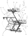
- FIG. 3 shows the region of the carrying and running structure, constructed in the manner of a scaffold of profile elements, of the self-propelled two-track stilt vehicle according to FIGS. 1 and 2 in transfer mode,
- FIG. 4 shows a detail, namely the left front corner region, of the scaffold-like region, shown in FIG. 3 , of the carrying and running structure of the self-propelled two-track stilt vehicle according to FIGS. 1 and 2 , and
- FIGS. 5A-5G show the loading of the stilt vehicle onto the associated transport trailer in several illustrated steps.
- the self-propelled two-track stilt vehicle shown in the drawing and designed, suitable and constructed for agricultural, horticultural and forestry applications comprises a running and carrying structure 1 and superstructures attached thereon in the form of a driver's cab 2 and a working mechanism 3 .
- the latter is constructed as a spreading mechanism 4 for spreading pest-control agents.
- the said running and carrying structure 1 comprises a region 5 constructed in the manner of a scaffold—joined together from profile elements—and four wheel units 6 , 7 disposed thereon with respectively a wheel-carrying unit 8 , 9 and a wheel 10 . 1 and 10 . 2 disposed thereon.
- Running and carrying structure 1 specifically its region 5 constructed in the manner of a scaffold joined together from profile elements, comprises a front transverse structure 11 . 1 oriented transversely relative to travel direction A and a rear transverse structure 11 . 2 likewise oriented transversely relative to travel direction A as well as two front stilt structures 12 . 1 —joined on both sides to front transverse structure 11 . 1 and two rear stilt structures 12 . 2 —joined on both sides to rear transverse structure 11 . 2 .
- Both front and rear transverse structures 11 . 1 and 11 . 2 are respectively constructed in several parts; they comprise respectively a middle piece 13 as well as left and right end pieces 14 .
- transverse spars 15 are constructed in the manner of frames; they consist substantially of respectively two transverse spars 15 , which are joined to one another via longitudinal spars 16 .
- Longitudinal spars 16 are disposed between the two transverse spars 15 (in the same plane as these) in such a way that the transverse spars 15 project laterally beyond longitudinal spars 16 .
- each transverse spar 15 an end piece 14 of the respective transverse structure 11 . 1 and 11 . 2 is disposed that is formed by a profile portion 17 .
- the respective end piece 14 may occupy various positions relative to the associated transverse spar 15 of middle piece 13 in question, namely especially a maximally extended position ( FIG. 1 ), a maximally retracted position ( FIG. 2 ) and any intermediate positions.
- clamping devices 18 disposed in the regions of the projections of transverse spars 15 , respectively end piece 14 can be fixed on the transverse spar 15 of middle piece 13 .
- the four stilt structures 12 . 1 and 12 . 2 are also respectively constructed in multiple parts. They comprise respectively a primary part 19 connected to the associated end piece 14 of the transverse structures 11 . 1 and 11 . 2 in question and a secondary part 20 , which can be fixed thereon in various height positions.
- the said primary part 19 of stilt structures 12 . 1 and 12 . 2 is respectively formed by two vertical profile portions 21 , which are joined rigidly to end pieces 14 of transverse structures 11 . 1 and 11 . 2 .
- the said respective connection regions are stiffened by angle fillers 22 as well as by connecting plates 23 .
- Secondary parts 20 of stilt structures 12 . 1 and 12 are also respectively constructed in multiple parts. They comprise respectively a primary part 19 connected to the associated end piece 14 of the transverse structures 11 . 1 and 11 . 2 in question and a secondary part 20 , which can be fixed thereon in various height positions.
- the said primary part 19 of stilt structures 12 . 1 and 12 . 2 is respectively formed by two vertical profile portions 21
- Secondary part 20 of stilt structures 12 . 1 and 12 . 2 can be disposed respectively at different heights relative to primary part 19 , especially in a maximally extended position ( FIG. 1 ) and a maximally retracted position ( FIG. 2 ) as well as any intermediate position and fixed there by means of clamping devices 27 acting between the profile portions 21 forming primary part 19 and vertical spars 24 of secondary parts 20 .
- a wheel-carrying unit 8 or 9 is attached to each of the secondary parts 20 of stilt structures 12 . 1 and 12 . 2 in the lower region.
- Carrying and running structure 1 further has a main frame 29 comprising two longitudinal beams 28 , to which middle pieces 13 of the two transverse structures 11 . 1 and 11 . 2 are attached.
- longitudinal beams 28 of main frame 29 are joined—via angle fillers 30 —to transverse spars 15 of middle pieces 13 of transverse structures 11 . 1 and 11 . 2 as well as—by means of clamped connections 31 —to longitudinal spars 16 , in contact with them from underneath, of middle pieces 13 of transverse structures 11 . 1 and 11 . 2 .
- Main frame 29 further comprises several transverse beams 33 extending between the two longitudinal beams 28 and—via angle fillers 32 —joined thereto.
- the said front transverse beam 33 of main frame 29 is joined via clamping devices 34 to front transverse spar 15 of middle piece 13 of front transverse structure 11 . 1 .
- transverse structures 11 . 1 and 11 . 2 , stilt structures 12 . 1 and 12 . 2 and main frame 29 have matching profile cross sections. They are portions of an extruded aluminum profile with substantially square-shaped basic cross section having respectively two T-shaped clamping slots on all four faces. For typical application situations of a manned stilt vehicle having a built-on mechanism of average weight, a profile having a square-shaped basic cross section with 9 cm edge length is favorable.
- the stilt vehicle is equipped with two driven, non-steerable rear wheels 10 . 2 and two steerable, non-driven front wheels 10 . 1 .
- an electrical steering mechanism 35 is integrated in each of the two front wheel-carrying units 8 , which are connected to secondary part 20 of the associated stilt structure 12 . 1 .
- This comprises respectively a steering motor 36 and a steering transmission 37 , the output shaft of which can be pivoted around a vertical axis.
- One branch of angle piece 38 on the other branch of which the respective front wheel 10 . 1 is pivotally mounted, is securely joined thereto.
- electrical drive motors 39 are integrated in rear wheel-carrying units 9 —which are connected to secondary parts 20 of the two rear stilt structures 12 . 2 . These are disposed above rear wheels 10 . 2 .
- the respective train comprises a height-displacement transmission 40 .
- the minimum width overall preferably does not exceed 2.15 m and particularly preferably is between 2.05 m and 2.15 m, especially approximately 2.12 m.
- the width of main frame 29 is preferably approximately between 1.1 m and 1.25 m, particularly preferably between 1.15 m and 1.2 m, especially approximately 1.18 m.
- transverse spars 15 of middle pieces 13 of transverse structures 11 . 1 and 11 . 2 preferably project, in transfer mode, approximately 15 cm to 20 cm, particularly preferably approximately 18 cm to 19 cm, especially approximately 18.5 cm beyond the maximally retracted end pieces 14 of the transverse structures.
- the loading process that takes place at the point of use—after use of the stilt vehicle explained in detail in the foregoing has been completed—on the associated trailer 43 provided with a cargo bed 42 braced on a chassis 41 , in order to transfer the stilt vehicle, may be configured as follows, as is illustrated schematically in the diagrams of FIGS. 5A-5G :
- the stilt vehicle adjusted from its use in “operating mode” to large track width (working track width) and large ground clearance (working height)—travels over trailer 43 , so that cargo bed 42 thereof is situated between the two tracks of the stilt vehicle ( FIG. 5A ).
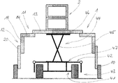
- Lifting device 44 which is associated with trailer 43 and braced thereon, and which may comprise, for example a hydraulic scissors lift 45 according to the sketch, is then urged upward until its upper carrying plate 46 reaches running and carrying structure 1 of the stilt vehicle, for example, the longitudinal beam 28 thereof (see above) and—with continued lifting movement of lifting device 44 —supports the stilt vehicle so strongly or lifts it so far that wheels 10 are unburdened ( FIG. 5B ) or even raised somewhat from ground B.
- Lifting device 44 which is associated with trailer 43 and braced thereon, and which may comprise, for example a hydraulic scissors lift 45 according to the sketch, is then urged upward until its upper carrying plate 46 reaches running and carrying structure 1 of the stilt vehicle, for example, the longitudinal beam 28 thereof (see above) and—with continued lifting movement of lifting device 44 —supports the stilt vehicle so strongly or lifts it so far that wheels 10 are unburdened ( FIG. 5B ) or even raised somewhat from ground B.
- lifting device 44 is provided with compensating arrangements 47 , 48 that—within narrow predetermined limits—permit lateral shifting (double arrow X) of the raised stilt vehicle and/or rotation (double arrow Y) of the stilt vehicle around a vertical axis Z, the stilt vehicle can now be positioned in its transfer mode exactly relative to cargo bed 42 of trailer 43 .
- the stilt vehicle which is therefore now situated—with respect to height and width—in its “transfer mode”, is lowered by means of lifting device 44 until it stands upright, with its wheels 10 on cargo bed 42 of trailer 43 ( FIG. 5F ).
- the stilt vehicle is secured in accordance with the applicable legal regulations.
- this also includes folding up (or moving upward) of trailer side parts 49 that may be present (see FIG. 5G ).
- Unloading of the stilt vehicle from trailer 43 takes place logically in reversed sequence compared with the loading described in the foregoing.
Abstract
Description
Claims (22)
Applications Claiming Priority (4)
| Application Number | Priority Date | Filing Date | Title |
|---|---|---|---|
| DE102016112292.0 | 2016-07-05 | ||
| DE102016112292.0A DE102016112292A1 (en) | 2016-07-05 | 2016-07-05 | Self-propelled two-lane stilts vehicle |
| DE102016112292 | 2016-07-05 | ||
| PCT/EP2017/066655 WO2018007395A1 (en) | 2016-07-05 | 2017-07-04 | Kit comprising a stilt vehicle and a trailer for transporting same |
Related Parent Applications (1)
| Application Number | Title | Priority Date | Filing Date |
|---|---|---|---|
| PCT/EP2017/066655 Continuation WO2018007395A1 (en) | 2016-07-05 | 2017-07-04 | Kit comprising a stilt vehicle and a trailer for transporting same |
Publications (2)
| Publication Number | Publication Date |
|---|---|
| US20190176911A1 US20190176911A1 (en) | 2019-06-13 |
| US10647365B2 true US10647365B2 (en) | 2020-05-12 |
Family
ID=59285211
Family Applications (1)
| Application Number | Title | Priority Date | Filing Date |
|---|---|---|---|
| US16/238,395 Active US10647365B2 (en) | 2016-07-05 | 2019-01-02 | Kit comprising a stilt vehicle and a trailer for transporting same |
Country Status (6)
| Country | Link |
|---|---|
| US (1) | US10647365B2 (en) |
| EP (1) | EP3283357B1 (en) |
| BR (1) | BR112018076777B1 (en) |
| CA (1) | CA3029865A1 (en) |
| DE (1) | DE102016112292A1 (en) |
| WO (1) | WO2018007395A1 (en) |
Families Citing this family (17)
| Publication number | Priority date | Publication date | Assignee | Title |
|---|---|---|---|---|
| DE102017119421A1 (en) * | 2017-08-24 | 2019-02-28 | Linde Material Handling Gmbh | Autonomous industrial truck, in particular order picking truck |
| WO2019056050A1 (en) * | 2017-09-19 | 2019-03-28 | Commonwealth Scientific And Industrial Research Organisation | Plant scanning vehicle |
| FR3078676B1 (en) * | 2018-03-06 | 2021-02-19 | Grv | FOUR-WHEEL DELTA SELF-PROPELLED SPACER VEHICLE |
| CN109080729B (en) * | 2018-06-20 | 2021-01-15 | 中国矿业大学 | Obstacle-surmounting mobile robot in pit |
| CN109572860A (en) * | 2019-01-28 | 2019-04-05 | 马骏 | A kind of stable type handling device with adjustable function for logistics |
| US10995901B2 (en) * | 2019-04-19 | 2021-05-04 | Honda Motor Co., Ltd. | Utility vehicle with deployable platform |
| CN110356467A (en) * | 2019-07-03 | 2019-10-22 | 三峡大学 | A kind of the four-wheel motor drive and control method of AGV trolley |
| CN110712694B (en) * | 2019-08-15 | 2021-09-28 | 燕山大学 | Six-freedom-degree parallel posture adjusting platform assembled based on four-leg low horizontal butt joint |
| CN110843956A (en) * | 2019-11-12 | 2020-02-28 | 广东博智林机器人有限公司 | AGV device |
| US20210219481A1 (en) * | 2020-01-21 | 2021-07-22 | David Haynes | Compact, extensible, track laying, agricultural tractor |
| DE102020113045A1 (en) | 2020-05-14 | 2021-11-18 | Bayerische Motoren Werke Aktiengesellschaft | Frame device for a handling device and handling device for handling a motor vehicle component |
| CN111645478B (en) * | 2020-05-27 | 2021-07-20 | 农业农村部南京农业机械化研究所 | Wheeled farmland management robot with flexible profiling chassis and profiling control method |
| CN112061264A (en) * | 2020-09-21 | 2020-12-11 | 临沂大学 | Multi-working-condition high-ground-clearance chassis |
| AT524318B1 (en) * | 2020-11-30 | 2022-05-15 | Miba Gleitlager Austria Gmbh | Plain bearing, and a gondola equipped with the plain bearing for a wind turbine |
| ES1265465Y (en) * | 2021-01-21 | 2022-02-10 | Ianus Ingenieria S L U | Multipurpose machine for growing trees. |
| WO2023066430A2 (en) * | 2021-10-22 | 2023-04-27 | Ai. Land Gmbh | Device for managing a usable agricultural area, and corresponding method |
| DE102022114860A1 (en) * | 2022-06-13 | 2023-12-14 | BIOCARE Gesellschaft für biologische Schutzmittel mit beschränkter Haftung | Self-propelled two-lane stilt vehicle |
Citations (12)
| Publication number | Priority date | Publication date | Assignee | Title |
|---|---|---|---|---|
| US3154164A (en) * | 1961-10-12 | 1964-10-27 | Cochran Equipment Company | Off-highway tractor |
| US4350222A (en) * | 1980-03-24 | 1982-09-21 | Lutteke Martin T | Variable tread vehicle |
| FR2550049A1 (en) | 1983-08-04 | 1985-02-08 | Pierrot Patrick | Machine for picking, processing and cultivation of fruit and vegetables |
| US4897987A (en) * | 1988-06-17 | 1990-02-06 | Spalla Pier L | Multipurpose and self-moving argicultural machine |
| US5039129A (en) | 1989-11-15 | 1991-08-13 | Charles Balmer | Vehicle for agricultural use |
| US20020053795A1 (en) | 2000-09-06 | 2002-05-09 | Schaffer James A. | Wheel support system for agricultural sprayer |
| US20050173601A1 (en) * | 2003-10-28 | 2005-08-11 | Hestand Larry D. | System for displaying a motor vehicle, apparatus and related methods |
| US20110024218A1 (en) | 2009-07-01 | 2011-02-03 | Sarl Grosjean Rene Viticole | self-propelled high-clearance vehicle |
| US20110073026A1 (en) | 2009-09-25 | 2011-03-31 | Martin Charles H | Agricultural vehicle and system |
| US8205893B2 (en) * | 2009-10-15 | 2012-06-26 | Agco Corporation | Variable chassis adjustment system |
| US20150034736A1 (en) | 2013-07-30 | 2015-02-05 | Winfield Solutions, Llc | High clearance adjustable sprayer |
| US20150102593A1 (en) | 2013-10-14 | 2015-04-16 | Agco Corporation | Vehicle with chassis height adjustment |
Family Cites Families (1)
| Publication number | Priority date | Publication date | Assignee | Title |
|---|---|---|---|---|
| US6386554B1 (en) * | 2000-02-02 | 2002-05-14 | Equipment Technologies, Inc. | Apparatus and method for operating a hydraulic suspension system of a crop sprayer |
-
2016
- 2016-07-05 DE DE102016112292.0A patent/DE102016112292A1/en not_active Withdrawn
-
2017
- 2017-07-04 WO PCT/EP2017/066655 patent/WO2018007395A1/en unknown
- 2017-07-04 BR BR112018076777-8A patent/BR112018076777B1/en active IP Right Grant
- 2017-07-04 CA CA3029865A patent/CA3029865A1/en not_active Abandoned
- 2017-07-04 EP EP17735505.4A patent/EP3283357B1/en active Active
-
2019
- 2019-01-02 US US16/238,395 patent/US10647365B2/en active Active
Patent Citations (13)
| Publication number | Priority date | Publication date | Assignee | Title |
|---|---|---|---|---|
| US3154164A (en) * | 1961-10-12 | 1964-10-27 | Cochran Equipment Company | Off-highway tractor |
| US4350222A (en) * | 1980-03-24 | 1982-09-21 | Lutteke Martin T | Variable tread vehicle |
| FR2550049A1 (en) | 1983-08-04 | 1985-02-08 | Pierrot Patrick | Machine for picking, processing and cultivation of fruit and vegetables |
| US4897987A (en) * | 1988-06-17 | 1990-02-06 | Spalla Pier L | Multipurpose and self-moving argicultural machine |
| US5039129A (en) | 1989-11-15 | 1991-08-13 | Charles Balmer | Vehicle for agricultural use |
| US20020053795A1 (en) | 2000-09-06 | 2002-05-09 | Schaffer James A. | Wheel support system for agricultural sprayer |
| US20050173601A1 (en) * | 2003-10-28 | 2005-08-11 | Hestand Larry D. | System for displaying a motor vehicle, apparatus and related methods |
| US20110024218A1 (en) | 2009-07-01 | 2011-02-03 | Sarl Grosjean Rene Viticole | self-propelled high-clearance vehicle |
| EP2448808B1 (en) | 2009-07-01 | 2013-08-14 | SARL Grosjean Rene Viticole | Self-propelled high-clearance vehicle |
| US20110073026A1 (en) | 2009-09-25 | 2011-03-31 | Martin Charles H | Agricultural vehicle and system |
| US8205893B2 (en) * | 2009-10-15 | 2012-06-26 | Agco Corporation | Variable chassis adjustment system |
| US20150034736A1 (en) | 2013-07-30 | 2015-02-05 | Winfield Solutions, Llc | High clearance adjustable sprayer |
| US20150102593A1 (en) | 2013-10-14 | 2015-04-16 | Agco Corporation | Vehicle with chassis height adjustment |
Non-Patent Citations (2)
| Title |
|---|
| International search report issued for corresponding International Patent Application No. PCT/EP2017/066655, dated Sep. 13, 2017 with an English Translation. |
| Written Opinion of the International Searching Authority for corresponding International Patent Application No. PCT/EP2017/066655, dated Sep. 13, 2017 with an English Translation. |
Also Published As
| Publication number | Publication date |
|---|---|
| EP3283357A1 (en) | 2018-02-21 |
| WO2018007395A1 (en) | 2018-01-11 |
| DE102016112292A1 (en) | 2018-01-11 |
| US20190176911A1 (en) | 2019-06-13 |
| BR112018076777A2 (en) | 2019-03-26 |
| EP3283357B1 (en) | 2019-03-06 |
| CA3029865A1 (en) | 2018-01-11 |
| BR112018076777B1 (en) | 2023-03-28 |
Similar Documents
| Publication | Publication Date | Title |
|---|---|---|
| US10647365B2 (en) | Kit comprising a stilt vehicle and a trailer for transporting same | |
| US8333401B2 (en) | Central multi directional transmission system | |
| KR101327367B1 (en) | Four-wheel drive cart for agriculture with device lift and dump | |
| RU2482992C2 (en) | Caterpillar track and forestry machine | |
| RU2741659C2 (en) | Transport platform | |
| US5582501A (en) | Fork lift and method for operating and transporting same | |
| FR3024084A1 (en) | CARRIER PALLET, INDIVIDUAL AND UNIVERSAL, FOR VEHICLE CAR RACK | |
| SE543484C2 (en) | Cargo handling vehicle for navigation in narrow aisles and method therefore | |
| US3993342A (en) | Convertible vehicle carrier | |
| US11805717B2 (en) | Self-propelled machine | |
| ES2710208T3 (en) | Low frame semi-trailer | |
| US8768538B2 (en) | Straddle carrier | |
| ES2254494T3 (en) | TWO-SIDED SYSTEM FOR LOADING TRUCKS. | |
| US7137641B1 (en) | Trailer apparatus | |
| SE435166B (en) | PROCEDURE AND CARGO TRANSPORT DEVICE FOR HANDLING AND TRANSPORTING A UNIT LOAD, CONSISTING OF ONE OR MORE CONTAINERS OR SIMILAR | |
| JPS606529A (en) | Method of loading car | |
| KR101334304B1 (en) | Four-wheel drive cart for agriculture with device tilting | |
| ES2254056T3 (en) | CHARGING AND DISCHARGE SYSTEM OF A STORAGE AREA. | |
| JP3030433B1 (en) | Truck for single rail transporter | |
| KR101872766B1 (en) | Traction type snow remover for trailer | |
| ES2608389T3 (en) | Device for moving carriers of products such as pallets | |
| RU2783562C2 (en) | Crane | |
| EP2774812B1 (en) | Method for manufacturing of a concrete element | |
| CN111727134B (en) | Chassis assembly for a transport vehicle | |
| US2676814A (en) | Tobacco leaf transorting vehicle |
Legal Events
| Date | Code | Title | Description |
|---|---|---|---|
| FEPP | Fee payment procedure |
Free format text: ENTITY STATUS SET TO UNDISCOUNTED (ORIGINAL EVENT CODE: BIG.); ENTITY STATUS OF PATENT OWNER: SMALL ENTITY |
|
| AS | Assignment |
Owner name: BIOCARE GESELLSCHAFT FUR BIOLOGISCHE SCHUTZMITTEL Free format text: ASSIGNMENT OF ASSIGNORS INTEREST;ASSIGNORS:BEITZEN-HEINEKE, WILHELM;SCHMIDT, STEPHAN;SCHUNEMANN, MARTIN;AND OTHERS;REEL/FRAME:048168/0916 Effective date: 20181211 Owner name: BIOCARE GESELLSCHAFT FUR BIOLOGISCHE SCHUTZMITTEL MBH, GERMANY Free format text: ASSIGNMENT OF ASSIGNORS INTEREST;ASSIGNORS:BEITZEN-HEINEKE, WILHELM;SCHMIDT, STEPHAN;SCHUNEMANN, MARTIN;AND OTHERS;REEL/FRAME:048168/0916 Effective date: 20181211 |
|
| FEPP | Fee payment procedure |
Free format text: ENTITY STATUS SET TO SMALL (ORIGINAL EVENT CODE: SMAL); ENTITY STATUS OF PATENT OWNER: SMALL ENTITY |
|
| STPP | Information on status: patent application and granting procedure in general |
Free format text: DOCKETED NEW CASE - READY FOR EXAMINATION |
|
| STPP | Information on status: patent application and granting procedure in general |
Free format text: NON FINAL ACTION MAILED |
|
| STPP | Information on status: patent application and granting procedure in general |
Free format text: RESPONSE TO NON-FINAL OFFICE ACTION ENTERED AND FORWARDED TO EXAMINER |
|
| STPP | Information on status: patent application and granting procedure in general |
Free format text: FINAL REJECTION MAILED |
|
| STPP | Information on status: patent application and granting procedure in general |
Free format text: NOTICE OF ALLOWANCE MAILED -- APPLICATION RECEIVED IN OFFICE OF PUBLICATIONS |
|
| STCF | Information on status: patent grant |
Free format text: PATENTED CASE |
|
| MAFP | Maintenance fee payment |
Free format text: PAYMENT OF MAINTENANCE FEE, 4TH YR, SMALL ENTITY (ORIGINAL EVENT CODE: M2551); ENTITY STATUS OF PATENT OWNER: SMALL ENTITY Year of fee payment: 4 |