US1061997A - Sign. - Google Patents
Sign. Download PDFInfo
- Publication number
- US1061997A US1061997A US72549612A US1912725496A US1061997A US 1061997 A US1061997 A US 1061997A US 72549612 A US72549612 A US 72549612A US 1912725496 A US1912725496 A US 1912725496A US 1061997 A US1061997 A US 1061997A
- Authority
- US
- United States
- Prior art keywords
- sign
- strips
- odset
- support
- portions
- Prior art date
- Legal status (The legal status is an assumption and is not a legal conclusion. Google has not performed a legal analysis and makes no representation as to the accuracy of the status listed.)
- Expired - Lifetime
Links
- 240000007839 Kleinhovia hospita Species 0.000 description 2
- 238000010276 construction Methods 0.000 description 1
Images
Classifications
-
- G—PHYSICS
- G09—EDUCATION; CRYPTOGRAPHY; DISPLAY; ADVERTISING; SEALS
- G09F—DISPLAYING; ADVERTISING; SIGNS; LABELS OR NAME-PLATES; SEALS
- G09F7/00—Signs, name or number plates, letters, numerals, or symbols; Panels or boards
- G09F7/18—Means for attaching signs, plates, panels, or boards to a supporting structure
Definitions
- This invention relates to i111provements in signs, and an object thereof fis'toprovide a sign member and a sup ⁇ ')ortin ⁇ g'v means therefor, in which no nails, screws or other fas-v tening means are used which would mar or disfigure the exposed surface of the sign member.
- a further object of this invention is the provision of a sign member anda holder therefor, in which the sign may be quickly' and easily secured toand detached from the holder.
- the numeral l indicates a stationary support which may be a door, fence or the ⁇ like
- 2 indicates a pair of spaced supporting strips which are secured to the statio-nary support along one longitudinal edge thereof by nails 3 or any other suitablefastening devices.
- the longitudinalk free edges of the strips are odset as atA t to form grooves 5, between the odset portions and the stationary support, and the bottom edges -of the strips are turned inwardly vupon themselves as at 6 to provide stops.
- the sign member 7 of my device is preferably in the form of a metallic plate
- Theoperation ⁇ of my device is as follows z-v-In the practical use of my sign, the supporting strips are secured to a stationary support at a suitable distance apart, and the flanges 8 of' the' sign member 7 are engaged upon the upper edges of the odset portions 4 of the strips, whereupon the sign member is moved downwardly until the lower edges of the flanges 8 rest within the pockets formed by the inwardlybent portions 6 at the lower edge of the strips whereupon the sign is rigidly supported upon the stationary support and with its fastening means lnvisible.
- a signl member comprising a plate having its opposite endedges formed with inwardly bent ianges, in lcombination with spaced supporting strips which are adapted to be secured at one longitudinal edgel to a suitable support, the longitudinal free edge of said strips being odset whereby pockets are formed'between the odset portions and the support, said odset portions extending out-Y wardly in opposite directions, the lower edge of each of said odset portions of the strips being formed with a flange, said flanges eX- tending inwardly and upwardly, the upwardly extending portion of the danges being adapted to rest against the supportlto entirely close the space ybetweenfthe lower' edge of ,Said strips and lsaidsupport, the end flanges of the sign member lbeing' adapted for engagement between the support and the odset portions of said supporting strips, and the flanges on the lower edge of said strips being adapted to limit the downward movement of said sign member.
Landscapes
- Physics & Mathematics (AREA)
- General Physics & Mathematics (AREA)
- Engineering & Computer Science (AREA)
- Theoretical Computer Science (AREA)
- Acyclic And Carbocyclic Compounds In Medicinal Compositions (AREA)
Description
F. E. FERGUSON.
SIGN. Y
'APPLICATION FILED 00T. 12, 1912.
1,061,997. Patnted May 20, 1913.
` n eww/Wmo Efguson) SMWMM @1t/toman,
FLOYD EDISON FERGUSON, ,OF WALLA WALLA, WASHINGTON.
SIGN.
l vSpecification of Letters Patent.
Patented May 20, 1913.
- Application led October 12, 1912. Serial No. 725,496.
To all 'whom t may ooncemf; n
Be it known that I, FLorD E. FERGUSON, a citizen of the Uni v`d, States, residing at Walla Walla, vin thedunty of Walla Walla and State of Washi gton, have invented certain new and useful Improvements in Signs, of/ which the following is a speciiication, reference being had to the accompanying drawings. f
This invention relates to i111provements in signs, and an object thereof fis'toprovide a sign member and a sup}')ortin`g'v means therefor, in which no nails, screws or other fas-v tening means are used which would mar or disfigure the exposed surface of the sign member. j
A further object of this invention is the provision of a sign member anda holder therefor, in which the sign may be quickly' and easily secured toand detached from the holder.
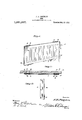
With these and other` objects in view, my invention resides in the construction and arrangement of parts to be hereinafter more fully described and illustrated inthe accompanying drawings, in which- Figure l is a perspective view opf-tghcfsign member showiig it attached to the supporting strips. Fig. l2 is a section taken on the line 2 2 of Fig. 1, and Fig. '3 is a perspective view of one of thesupporting strips for the sign member. p Referring more particularly to the draw'- ings, the numeral l indicates a stationary support which may be a door, fence or the` like, and 2 indicates a pair of spaced supporting strips which are secured to the statio-nary support along one longitudinal edge thereof by nails 3 or any other suitablefastening devices. The longitudinalk free edges of the strips are odset as atA t to form grooves 5, between the odset portions and the stationary support, and the bottom edges -of the strips are turned inwardly vupon themselves as at 6 to provide stops.
The sign member 7 of my device is preferably in the form of a metallic plate, the
opposite side edges of which are bent inwardly to form danges 8 which are adapted to Aengage the grooves 5 between the odset portions 4 of the supporting strips and the support 1. 1 I
Theoperation `of my device is as follows z-v-In the practical use of my sign, the supporting strips are secured to a stationary support at a suitable distance apart, and the flanges 8 of' the' sign member 7 are engaged upon the upper edges of the odset portions 4 of the strips, whereupon the sign member is moved downwardly until the lower edges of the flanges 8 rest within the pockets formed by the inwardlybent portions 6 at the lower edge of the strips whereupon the sign is rigidly supported upon the stationary support and with its fastening means lnvisible.
From the above description taken in connection with the accompanying drawings, it will be seen that I have provided a sign which may be secured to a suitable support without the use of nails, screws or other fastening means which may mar or deface the visibl/ face of the sign, and'one which may be, qtuckly and easily applied to its sup- 'porting strips.
Having thus described my invention, what Iclaim is:-
A signl member comprising a plate having its opposite endedges formed with inwardly bent ianges, in lcombination with spaced supporting strips which are adapted to be secured at one longitudinal edgel to a suitable support, the longitudinal free edge of said strips being odset whereby pockets are formed'between the odset portions and the support, said odset portions extending out-Y wardly in opposite directions, the lower edge of each of said odset portions of the strips being formed with a flange, said flanges eX- tending inwardly and upwardly, the upwardly extending portion of the danges being adapted to rest against the supportlto entirely close the space ybetweenfthe lower' edge of ,Said strips and lsaidsupport, the end flanges of the sign member lbeing' adapted for engagement between the support and the odset portions of said supporting strips, and the flanges on the lower edge of said strips being adapted to limit the downward movement of said sign member.
In testimony whereof I hereunto adix my signature in the presence of two witnesses.
FLOYD EDISON FERGUSON. Witnesses:
L. R. HAWLEY, "S. E. KING.
Priority Applications (1)
| Application Number | Priority Date | Filing Date | Title |
|---|---|---|---|
| US72549612A US1061997A (en) | 1912-10-12 | 1912-10-12 | Sign. |
Applications Claiming Priority (1)
| Application Number | Priority Date | Filing Date | Title |
|---|---|---|---|
| US72549612A US1061997A (en) | 1912-10-12 | 1912-10-12 | Sign. |
Publications (1)
| Publication Number | Publication Date |
|---|---|
| US1061997A true US1061997A (en) | 1913-05-20 |
Family
ID=3130243
Family Applications (1)
| Application Number | Title | Priority Date | Filing Date |
|---|---|---|---|
| US72549612A Expired - Lifetime US1061997A (en) | 1912-10-12 | 1912-10-12 | Sign. |
Country Status (1)
| Country | Link |
|---|---|
| US (1) | US1061997A (en) |
-
1912
- 1912-10-12 US US72549612A patent/US1061997A/en not_active Expired - Lifetime
Similar Documents
| Publication | Publication Date | Title |
|---|---|---|
| US1308869A (en) | Cable and wire clamp. | |
| US1061997A (en) | Sign. | |
| US1786038A (en) | Apparatus for map display | |
| US806677A (en) | Bracket and support. | |
| US993818A (en) | Sign. | |
| US344555A (en) | Feedebick a | |
| US1513017A (en) | Signal | |
| US926374A (en) | Show-case. | |
| US1246095A (en) | Mirror-glass-fastener. | |
| US889844A (en) | Sheet-metal shelf. | |
| US1205800A (en) | Sign-holder. | |
| US549337A (en) | Glass sign | |
| US868200A (en) | Door-stop. | |
| US907615A (en) | Postal-card holder. | |
| US496931A (en) | Territory | |
| US971816A (en) | Window-pane fastener. | |
| US1252130A (en) | Shade-hanger. | |
| US1096660A (en) | Display-rack for windows. | |
| US1018603A (en) | Window-screen hanger. | |
| US200688A (en) | Improvement in label-holders | |
| US1114810A (en) | Combined hanger and lift. | |
| US1718622A (en) | Illuminated house number | |
| US513714A (en) | Card-holder | |
| US987070A (en) | Illuminated sign. | |
| US817460A (en) | Tag or label. |