US10616458B2 - Imaging apparatus and image processing method - Google Patents
Imaging apparatus and image processing method Download PDFInfo
- Publication number
- US10616458B2 US10616458B2 US16/135,308 US201816135308A US10616458B2 US 10616458 B2 US10616458 B2 US 10616458B2 US 201816135308 A US201816135308 A US 201816135308A US 10616458 B2 US10616458 B2 US 10616458B2
- Authority
- US
- United States
- Prior art keywords
- light
- light sources
- illumination light
- imaging
- imaging apparatus
- Prior art date
- Legal status (The legal status is an assumption and is not a legal conclusion. Google has not performed a legal analysis and makes no representation as to the accuracy of the status listed.)
- Active, expires
Links
- 238000003384 imaging method Methods 0.000 title claims abstract description 206
- 238000003672 processing method Methods 0.000 title claims description 7
- 238000005286 illumination Methods 0.000 claims abstract description 185
- 230000035945 sensitivity Effects 0.000 claims abstract description 119
- 239000003086 colorant Substances 0.000 claims abstract description 70
- 230000003595 spectral effect Effects 0.000 claims description 66
- 230000001678 irradiating effect Effects 0.000 claims description 5
- 230000003287 optical effect Effects 0.000 claims description 2
- 239000013598 vector Substances 0.000 description 93
- 238000009826 distribution Methods 0.000 description 34
- 238000000034 method Methods 0.000 description 16
- 238000006243 chemical reaction Methods 0.000 description 10
- 239000000126 substance Substances 0.000 description 9
- 238000004458 analytical method Methods 0.000 description 4
- 238000010586 diagram Methods 0.000 description 4
- 230000007423 decrease Effects 0.000 description 3
- 238000007792 addition Methods 0.000 description 2
- 239000011159 matrix material Substances 0.000 description 2
- 238000010606 normalization Methods 0.000 description 1
- 230000002093 peripheral effect Effects 0.000 description 1
- 238000004451 qualitative analysis Methods 0.000 description 1
- 238000004445 quantitative analysis Methods 0.000 description 1
- 238000005070 sampling Methods 0.000 description 1
- 230000002123 temporal effect Effects 0.000 description 1
- 230000009466 transformation Effects 0.000 description 1
Images


Classifications
-
- H04N5/2256—
-
- H—ELECTRICITY
- H04—ELECTRIC COMMUNICATION TECHNIQUE
- H04N—PICTORIAL COMMUNICATION, e.g. TELEVISION
- H04N23/00—Cameras or camera modules comprising electronic image sensors; Control thereof
- H04N23/56—Cameras or camera modules comprising electronic image sensors; Control thereof provided with illuminating means
-
- G—PHYSICS
- G01—MEASURING; TESTING
- G01J—MEASUREMENT OF INTENSITY, VELOCITY, SPECTRAL CONTENT, POLARISATION, PHASE OR PULSE CHARACTERISTICS OF INFRARED, VISIBLE OR ULTRAVIOLET LIGHT; COLORIMETRY; RADIATION PYROMETRY
- G01J3/00—Spectrometry; Spectrophotometry; Monochromators; Measuring colours
- G01J3/02—Details
- G01J3/10—Arrangements of light sources specially adapted for spectrometry or colorimetry
-
- G—PHYSICS
- G01—MEASURING; TESTING
- G01J—MEASUREMENT OF INTENSITY, VELOCITY, SPECTRAL CONTENT, POLARISATION, PHASE OR PULSE CHARACTERISTICS OF INFRARED, VISIBLE OR ULTRAVIOLET LIGHT; COLORIMETRY; RADIATION PYROMETRY
- G01J3/00—Spectrometry; Spectrophotometry; Monochromators; Measuring colours
- G01J3/28—Investigating the spectrum
- G01J3/2803—Investigating the spectrum using photoelectric array detector
-
- G—PHYSICS
- G01—MEASURING; TESTING
- G01J—MEASUREMENT OF INTENSITY, VELOCITY, SPECTRAL CONTENT, POLARISATION, PHASE OR PULSE CHARACTERISTICS OF INFRARED, VISIBLE OR ULTRAVIOLET LIGHT; COLORIMETRY; RADIATION PYROMETRY
- G01J3/00—Spectrometry; Spectrophotometry; Monochromators; Measuring colours
- G01J3/28—Investigating the spectrum
- G01J3/2823—Imaging spectrometer
-
- G—PHYSICS
- G01—MEASURING; TESTING
- G01J—MEASUREMENT OF INTENSITY, VELOCITY, SPECTRAL CONTENT, POLARISATION, PHASE OR PULSE CHARACTERISTICS OF INFRARED, VISIBLE OR ULTRAVIOLET LIGHT; COLORIMETRY; RADIATION PYROMETRY
- G01J3/00—Spectrometry; Spectrophotometry; Monochromators; Measuring colours
- G01J3/46—Measurement of colour; Colour measuring devices, e.g. colorimeters
-
- G—PHYSICS
- G02—OPTICS
- G02B—OPTICAL ELEMENTS, SYSTEMS OR APPARATUS
- G02B5/00—Optical elements other than lenses
- G02B5/20—Filters
-
- H05B33/0845—
-
- H05B33/0857—
-
- H—ELECTRICITY
- H05—ELECTRIC TECHNIQUES NOT OTHERWISE PROVIDED FOR
- H05B—ELECTRIC HEATING; ELECTRIC LIGHT SOURCES NOT OTHERWISE PROVIDED FOR; CIRCUIT ARRANGEMENTS FOR ELECTRIC LIGHT SOURCES, IN GENERAL
- H05B45/00—Circuit arrangements for operating light-emitting diodes [LED]
- H05B45/20—Controlling the colour of the light
-
- H—ELECTRICITY
- H05—ELECTRIC TECHNIQUES NOT OTHERWISE PROVIDED FOR
- H05B—ELECTRIC HEATING; ELECTRIC LIGHT SOURCES NOT OTHERWISE PROVIDED FOR; CIRCUIT ARRANGEMENTS FOR ELECTRIC LIGHT SOURCES, IN GENERAL
- H05B47/00—Circuit arrangements for operating light sources in general, i.e. where the type of light source is not relevant
- H05B47/10—Controlling the light source
- H05B47/105—Controlling the light source in response to determined parameters
- H05B47/115—Controlling the light source in response to determined parameters by determining the presence or movement of objects or living beings
- H05B47/125—Controlling the light source in response to determined parameters by determining the presence or movement of objects or living beings by using cameras
-
- G—PHYSICS
- G01—MEASURING; TESTING
- G01J—MEASUREMENT OF INTENSITY, VELOCITY, SPECTRAL CONTENT, POLARISATION, PHASE OR PULSE CHARACTERISTICS OF INFRARED, VISIBLE OR ULTRAVIOLET LIGHT; COLORIMETRY; RADIATION PYROMETRY
- G01J3/00—Spectrometry; Spectrophotometry; Monochromators; Measuring colours
- G01J3/12—Generating the spectrum; Monochromators
- G01J2003/1282—Spectrum tailoring
-
- G—PHYSICS
- G01—MEASURING; TESTING
- G01J—MEASUREMENT OF INTENSITY, VELOCITY, SPECTRAL CONTENT, POLARISATION, PHASE OR PULSE CHARACTERISTICS OF INFRARED, VISIBLE OR ULTRAVIOLET LIGHT; COLORIMETRY; RADIATION PYROMETRY
- G01J3/00—Spectrometry; Spectrophotometry; Monochromators; Measuring colours
- G01J3/28—Investigating the spectrum
- G01J3/2803—Investigating the spectrum using photoelectric array detector
- G01J2003/2806—Array and filter array
-
- G—PHYSICS
- G01—MEASURING; TESTING
- G01J—MEASUREMENT OF INTENSITY, VELOCITY, SPECTRAL CONTENT, POLARISATION, PHASE OR PULSE CHARACTERISTICS OF INFRARED, VISIBLE OR ULTRAVIOLET LIGHT; COLORIMETRY; RADIATION PYROMETRY
- G01J3/00—Spectrometry; Spectrophotometry; Monochromators; Measuring colours
- G01J3/28—Investigating the spectrum
- G01J3/2823—Imaging spectrometer
- G01J2003/2826—Multispectral imaging, e.g. filter imaging
-
- G—PHYSICS
- G01—MEASURING; TESTING
- G01J—MEASUREMENT OF INTENSITY, VELOCITY, SPECTRAL CONTENT, POLARISATION, PHASE OR PULSE CHARACTERISTICS OF INFRARED, VISIBLE OR ULTRAVIOLET LIGHT; COLORIMETRY; RADIATION PYROMETRY
- G01J3/00—Spectrometry; Spectrophotometry; Monochromators; Measuring colours
- G01J3/28—Investigating the spectrum
- G01J3/30—Measuring the intensity of spectral lines directly on the spectrum itself
- G01J3/36—Investigating two or more bands of a spectrum by separate detectors
-
- Y—GENERAL TAGGING OF NEW TECHNOLOGICAL DEVELOPMENTS; GENERAL TAGGING OF CROSS-SECTIONAL TECHNOLOGIES SPANNING OVER SEVERAL SECTIONS OF THE IPC; TECHNICAL SUBJECTS COVERED BY FORMER USPC CROSS-REFERENCE ART COLLECTIONS [XRACs] AND DIGESTS
- Y02—TECHNOLOGIES OR APPLICATIONS FOR MITIGATION OR ADAPTATION AGAINST CLIMATE CHANGE
- Y02B—CLIMATE CHANGE MITIGATION TECHNOLOGIES RELATED TO BUILDINGS, e.g. HOUSING, HOUSE APPLIANCES OR RELATED END-USER APPLICATIONS
- Y02B20/00—Energy efficient lighting technologies, e.g. halogen lamps or gas discharge lamps
- Y02B20/40—Control techniques providing energy savings, e.g. smart controller or presence detection
Definitions
- the present disclosure relates to an imaging apparatus that performs an arithmetic operation to generate a plurality of images including information about reflected light that has been reflected by a subject, and an image processing method.
- PTL 1 discloses a color conversion coefficient calculator.
- the color conversion coefficient calculator calculates a color conversion coefficient for converting a first color signal made up of a plurality of color signals into a second color signal made up of a plurality of color signals.
- the color conversion coefficient calculator includes color conversion coefficient calculation means, correction coefficient calculation means, and coefficient correction means.
- the color conversion coefficient calculation means calculates a color conversion coefficient for converting a first spectral characteristic that characterizes the first color signal in a standard fashion into a second spectral characteristic that characterizes the second color signal.
- the correction coefficient calculation means calculates a correction coefficient for approximating a base color signal serving as a first color signal that corresponds to a plurality of base colors to a reference color signal that is obtained based on the first spectral characteristic in accordance with the plurality of base colors.
- the coefficient correction means corrects the color conversion coefficient by using the correction coefficient.
- the base color signal is a first color signal that is obtained by imaging color patches of a plurality of colors that correspond to the plurality of base colors.
- the reference color signal is a color signal that is obtained based on spectral characteristics of the color patches of the plurality of colors and the first spectral characteristic. Each of the color patches is a color patch that emits light in a specified narrow band.
- the color conversion coefficient calculator described above can easily realize high-precision color conversion processing according to a difference between individuals in addition to a difference between models.
- the present disclosure provides an imaging apparatus that performs an arithmetic operation to generate a plurality of images that each only include information about monochromatic reflected light from a single captured image, and an image processing method.
- the imaging apparatus includes a lighting unit, an imaging unit, a memory, and an arithmetic unit.
- the lighting unit includes a plurality of light sources that respectively emit rays of monochromatic illumination light that have center wavelengths different from each other.
- the lighting unit simultaneously irradiates a subject with plural rays of illumination light emitted by the plurality of light sources.
- the imaging unit simultaneously images plural rays of reflected light obtained by the plural rays of illumination light being reflected by the subject so as to obtain information about a plurality of colors, and the imaging unit generates a captured image including the information about the plurality of colors.
- the memory stores sensitivity information items that correspond to the plurality of light sources respectively and each of the sensitivity information items relates to sensitivities of the imaging unit to the plurality of colors.
- the arithmetic unit performs an arithmetic operation to generate a plurality of separated images from the captured image by using the sensitivity information items.
- the plurality of separated images corresponds to the plurality of light sources respectively.
- Each of the plurality of separated images only includes information about a corresponding one of the plural rays of reflected light.
- the image processing method includes an irradiation step, an imaging step, and an arithmetic step.
- the irradiation step is a step of simultaneously irradiating a subject with plural rays of illumination light emitted by a plurality of light sources, the plurality of light sources respectively emitting the plural rays of illumination light that are monochromatic and that have center wavelengths different from each other.
- the imaging step is a step of simultaneously imaging, by the imaging unit, plural rays of reflected light obtained by the plural rays of illumination light being reflected by the subject so as to obtain information about a plurality of colors, and of generating a captured image including the information about the plurality of colors.
- the arithmetic step is a step of performing an arithmetic operation to generate a plurality of separated images from the captured image by using sensitivity information items.
- the sensitivity information items correspond to the plurality of light sources respectively and each of the sensitivity information items relates to sensitivities of the imaging unit to the plurality of colors.
- the plurality of separated images correspond to the plurality of light sources respectively, and each of the plurality of separated images only includes information about a corresponding one of the plural rays of reflected light.
- the imaging apparatus and the image processing method according to the present disclosure can perform an arithmetic operation to generate a plurality of images that each only include information about monochromatic reflected light from a single captured image. Further, the imaging apparatus and the image processing method according to the present disclosure can increase a degree of freedom in selection of a wavelength that corresponds to each of the plurality of images.
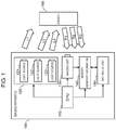
- FIG. 1 is a block diagram illustrating a configuration of an imaging apparatus according to a first exemplary embodiment.
- FIG. 2 illustrates spectral sensitivity characteristics of an imaging unit according to the first exemplary embodiment.
- FIG. 3 is a flowchart for describing an operation of the imaging apparatus according to the first exemplary embodiment.
- FIG. 4 is a block diagram illustrating a configuration of an imaging apparatus according to a second exemplary embodiment.
- FIG. 5 is a flowchart for describing an operation of the imaging apparatus according to the second exemplary embodiment.
- a first exemplary embodiment is described below with reference to FIGS. 1 to 3 .
- Reflected light is light that is reflected by a substance when the substance is irradiated with light, and reflects characteristics of the substance. Accordingly, the reflected light is utilized for qualitative and quantitative analysis of the substance.
- a spectral distribution is obtained, for example, by continuously splitting light into rays of light of respective wavelengths by using a diffraction grating.
- the spectral distribution indicates a distribution of an intensity of light of each of the wavelengths.
- a spectral distribution of reflected light reflects characteristics of a substance that reflects light.
- the spectral distribution of the reflected light is expressed by a graph in which a horizontal axis indicates a wavelength and a vertical axis indicates an intensity of the reflected light of each wavelength.
- a distribution shape in the graph reflects qualitative information of the substance.
- a total intensity in the graph reflects quantitative information of the substance.
- a spectral distribution indicating the qualitative information is referred to as a relative spectral distribution.
- an RGB value of each pixel of a captured image generated by capturing an image using an RGB camera is considered as a three-dimensional vector, and the RGB value is referred to as an RGB vector.
- a direction and a length of the RGB vector are described below.
- R means red
- G means green
- B means blue.
- the direction of the RGB vector is information that reflects a ratio of values of respective colors of the RGB value.
- a direction of an RGB vector of reflected light includes information relating to a qualitative characteristic of a substance that reflects light. Stated another way, the direction of the RGB vector of the reflected light relates to the relative spectral distribution. For example, an RGB vector with a length normalized to 1 can be used as the direction of the RGB vector.
- the length of the RGB vector is a value that reflects a total intensity of the RGB value.
- a length of the RGB vector of the reflected light includes information relating to a quantitative characteristic of a substance that reflects light.
- An R value is obtained by multiplying a spectral distribution of the observation light by a spectral sensitivity characteristic of R of the RGB camera and integrating the obtained value.
- a G value is obtained by multiplying the spectral distribution of the observation light by a spectral sensitivity characteristic of G of the RGB camera and integrating the obtained value.
- a B value is obtained by multiplying the spectral distribution of the observation light by a spectral sensitivity characteristic of B of the RGB camera and integrating the obtained value.
- the direction of the RGB vector includes information about the relative spectral distribution of the observation light.
- the length of the RGB vector includes information relating to an intensity in the spectral distribution of the observation light.
- the RGB vector is also one example of the spectral distribution and that the direction of the RGB vector is also one example of the relative spectral distribution. Accordingly, the RGB vector is also referred to as a spectral distribution, and the direction of the RGB vector is also referred to as a relative spectral distribution.
- an RGB vector of reflected light obtained by irradiating a certain subject with light having a certain intensity is vector V 1
- an RGB vector of reflected light obtained by irradiating the subject with light having a double intensity is vector V 2 .
- directions of vector V 1 and vector V 2 are not different from each other, but a length of vector V 2 is twice a length of vector V 1 .
- FIG. 1 is a block diagram illustrating a configuration of imaging apparatus 100 according to the first exemplary embodiment.
- Imaging apparatus 100 includes central processing unit (CPU) 110 , lighting unit 120 , imaging unit 130 , memory 140 , and arithmetic unit 150 .
- Lighting unit 120 includes light source 121 , light source 122 , and light source 123 that emit respective rays of monochromatic illumination light that have relative spectral distributions different from each other.
- CPU 110 instructs the respective components to perform an operation.
- CPU 110 instructs lighting unit 120 to turn on or off light source 121 , light source 122 , and light source 123 .
- CPU 110 also instructs imaging unit 130 to capture an image.
- CPU 110 instructs arithmetic unit to perform an arithmetic operation.
- Lighting unit 120 simultaneously irradiates subject 160 with plural rays of illumination light emitted by light source 121 , light source 122 , and light source 123 .
- a number of light sources means a number of light sources that emit respective rays of monochromatic illumination light that have relative spectral distributions different from each other.
- Respective rays of illumination light emitted by light source 121 , light source 122 , and light source 123 have center wavelengths different from each other.
- a center wavelength that illumination light has is, for example, a wavelength at which an intensity of the illumination light becomes maximum in a spectral distribution of the illumination light.
- lighting unit 120 includes light source 121 , light source 122 , and light source 123 that emit respective rays of monochromatic illumination light that have center wavelengths different from each other. Lighting unit 120 simultaneously irradiates subject 160 with plural rays of illumination light emitted by light source 121 , light source 122 , and light source 123 .
- the monochromatic light is not limited to light that only has a single wavelength.
- the monochromatic light may have a wavelength band that a normal light emitting diode (LED) has.
- each of light source 121 , light source 122 , and light source 123 is, for example, an LED.
- Light source 121 emits illumination light L 1 having a center wavelength of 450 nm.
- Light source 122 emits illumination light L 2 having a center wavelength of 550 nm.
- Light source 123 emits illumination light L 3 having a center wavelength of 650 nm.
- Lighting unit 120 causes light source 121 , light source 122 , and light source 123 to simultaneously emit light in accordance with an instruction from CPU 110 , and lighting unit 120 simultaneously irradiates subject 160 with illumination light L 1 , illumination light L 2 , and illumination light L 3 .
- Subject 160 reflects the illumination light emitted by each of the light sources.
- FIG. 1 assume that light obtained by illumination light L 1 being reflected by subject 160 is reflected light R 1 . Also assume that light obtained by illumination light L 2 being reflected by subject 160 is reflected light R 2 . Further, assume that light obtained by illumination light L 3 being reflected by subject 160 is reflected light R 3 .
- An intensity of reflected light R 1 is obtained by multiplying an intensity of illumination light L 1 by a reflectance of subject 160 at a wavelength of illumination light L 1 .
- An intensity of reflected light R 2 is obtained by multiplying an intensity of illumination light L 2 by a reflectance of subject 160 at a wavelength of illumination light L 2 .
- An intensity of reflected light R 3 is obtained by multiplying an intensity of illumination light L 3 by a reflectance of subject 160 at a wavelength of illumination light L 3 .
- lighting unit 120 simultaneously irradiates subject 160 with illumination light L 1 , illumination light L 2 , and illumination light L 3 , and therefore light reflected by subject 160 is light in which reflected light R 1 , reflected light R 2 , and reflected light R 3 are mixed.
- the intensities of the respective rays of illumination light may be identical to each other, or may be different from each other. As described later, it is desirable that the intensities of the respective rays of reflected light be almost equal to each other. Accordingly, when a spectral reflectance of subject 160 is known in advance, the intensities of the respective rays of illumination light may be set according to respective reflectances of subject 160 that correspond to the center wavelengths of the respective rays of illumination light.
- a ratio of reflectances of subject 160 that respectively correspond to the center wavelengths of illumination light L 1 , illumination light L 2 , and illumination light L 3 is 1:2:4
- a ratio of the intensities of illumination light L 1 , illumination light L 2 , and illumination light L 3 may be set to 4:2:1.
- the respective intensities of reflected light R 1 , reflected light R 2 , and reflected light R 3 become almost equal to each other because an intensity of reflected light is the product of an intensity of illumination light and a reflectance of subject 160 .
- an intensity of illumination light of each of a plurality of light sources may be greater than an intensity of other illumination light having a center wavelength that corresponds to a reflectance of subject 160 that is greater than a reflectance of subject 160 that corresponds to a center wavelength of the illumination light of each of the plurality of light sources.
- the intensity of illumination light L 2 is greater than the intensity of illumination light L 3 having a center wavelength (650 nm) that corresponds to a reflectance of subject 160 that is greater than a reflectance of subject 160 that corresponds to the center wavelength (550 nm) of illumination light L 2 .
- Imaging unit 130 includes a lens and an imaging element.
- the lens included in imaging unit 130 forms, on the imaging element, an image of subject 160 using reflected light R 1 , reflected light R 2 , and reflected light R 3 that have been reflected by subject 160 .
- the imaging element included in imaging unit 130 has pixels of an RGB Bayer array, and obtains information about three colors. In other words, imaging unit 130 operates as an RGB camera. Imaging unit 130 simultaneously images reflected light R 1 , reflected light R 2 , and reflected light R 3 so as to obtain information about three colors, and generates a captured image including the information about the three colors. Imaging unit 130 stores the generated captured image in memory 140 .
- FIG. 2 illustrates spectral sensitivity characteristics of imaging unit 130 according to the present exemplary embodiment.
- a horizontal axis indicates a wavelength
- a vertical axis indicates sensitivity to each color of RGB of imaging unit 130 .
- a dotted line indicates an R spectral sensitivity characteristic of imaging unit 130
- a solid line indicates a G spectral sensitivity characteristic of imaging unit 130
- a broken line indicates a B spectral sensitivity characteristic of imaging unit 130 .
- the spectral sensitivity characteristics of the three colors of imaging unit 130 have areas that overlap each other. Stated another way, imaging unit 130 has sensitivity to a plurality of colors with respect to monochromatic light having any center wavelength.
- Imaging unit 130 simultaneously images reflected light R 1 , reflected light R 2 , and reflected light R 3 . Stated another way, imaging unit 130 images light in which reflected light R 1 , reflected light R 2 , and reflected light R 3 are mixed. In addition, imaging unit 130 has sensitivity to three colors with respect to all of reflected light R 1 , reflected light R 2 , and reflected light R 3 , as illustrated in FIG. 2 . Therefore, in a pixel of each of the colors, an image in which reflected light R 1 , reflected light R 2 , and reflected light R 3 are mixed is captured.
- a sensitivity to each color of imaging unit 130 that corresponds to wavelength ⁇ (nm) is described with reference to FIG. 2 .
- the R spectral sensitivity characteristic of imaging unit 130 is R( ⁇ )
- the G spectral sensitivity characteristic of imaging unit 130 is G( ⁇ )
- the B spectral sensitivity characteristic of imaging unit 130 is B( ⁇ ).
- B(450), G(450), and R(450) are sensitivities to the respective colors of imaging unit 130 that correspond to a wavelength of 450 nm
- B(450), G(450), and R(450) are illustrated in FIG. 2 .
- a sensitivity to each of the colors of imaging unit 130 that corresponds to a certain wavelength is also referred to as a sensitivity to each of the colors of imaging unit 130 that corresponds to a certain light source. This means a sensitivity to each of the colors of imaging unit 130 that corresponds to a center wavelength of the certain light source.
- the spectral sensitivity characteristics of the three colors of imaging unit 130 have areas that overlap each other.
- Center wavelengths of light source 121 , light source 122 , and light source 123 are 450 nm, 550 nm, and 650 nm, respectively.
- a sensitivity to each of the colors of imaging unit 130 that corresponds to the center wavelength (450 nm) of light source 121 is expressed by RGB vector (B(450), G(450), R(450)).
- a sensitivity to each of the colors of imaging unit 130 that corresponds to the center wavelength (550 nm) of light source 122 is expressed by RGB vector (B(550), G(550), R(550)).
- a sensitivity to each of the colors of imaging unit 130 that corresponds to the center wavelength (650 nm) of light source 123 is expressed by RGB vector (B(650), G(650), R(650)). These RGB vectors are linearly independent of each other. Stated another way, the sensitivities to each of the colors of imaging unit 130 that correspond to the respective center wavelengths of light source 121 , light source 122 , and light source 123 are linearly independent of each other.
- Memory 140 stores the captured image generated by imaging unit 130 .
- memory 140 is used as a work memory of arithmetic unit 150 .
- memory 140 stores information relating to the sensitivity to each of the colors of imaging unit 130 that corresponds to each of the light sources.
- the information relating to the sensitivity to each of the colors of imaging unit 130 is referred to as sensitivity information.
- memory 140 stores sensitivity information that corresponds to each of light source 121 , light source 122 , and light source 123 as sensitivity information that corresponds to each of the light sources.
- the sensitivity information is information relating to a direction of an RGB vector obtained by imaging each of illumination light L 1 , illumination light L 2 , and illumination light L 3 using imaging unit 130 .
- the sensitivity information that corresponds to each of the light sources is a vector that includes information relating to a relative spectral distribution of each of illumination light L 1 , illumination light L 2 , and illumination light L 3 , and the spectral sensitivity characteristics of imaging unit 130 . Assume that this vector is normalized to have a length of 1.
- the sensitivity information is stored in advance in memory 140 .
- the sensitivity information is obtained, for example, by directly imaging illumination light of each of the light sources using imaging unit 130 .
- the obtained sensitivity information is normalized and is stored in memory 140 .
- Arithmetic unit 150 performs an arithmetic operation to generate a plurality of separated images from the captured image generated by imaging unit 130 , by using the sensitivity information stored in memory 140 .
- Each of the plurality of separated images only includes information about reflected light that corresponds to each of the light sources. Details of the arithmetic operation will be described later.
- Reflected light that corresponds to light source 121 is reflected light R 1
- reflected light that corresponds to light source 122 is reflected light R 2
- reflected light that corresponds to light source 123 is reflected light R 3 .
- the reflected light that corresponds to each of the light sources means reflected light that is derived from illumination light emitted by a corresponding light source from among rays of reflected light that are reflected by subject 160 .
- arithmetic unit 150 performs an arithmetic operation to generate a separated image that only includes information about reflected light R 1 , a separated image that only includes information about reflected light R 2 , and a separated image that only includes information about reflected light R 3 from the captured image generated by imaging unit 130 , by using the sensitivity information that corresponds to each of light source 121 , light source 122 , and light source 123 .
- arithmetic unit 150 performs an arithmetic operation to generate a plurality of separated images for the center wavelengths of the respective light sources.
- only light source 121 , light source 122 , and light source 123 are used in the imaging of subject 160 , and subject 160 is imaged in a darkroom.
- imaging apparatus 100 An operation of imaging apparatus 100 configured as described above is described below.
- FIG. 3 is a flowchart for describing the operation of imaging apparatus 100 .
- Step S 201 CPU 110 instructs lighting unit 120 to turn on light source 121 , light source 122 , and light source 123 .
- Lighting unit 120 turns on light source 121 , light source 122 , and light source 123 , and simultaneously irradiates subject 160 with illumination light L 1 , illumination light L 2 , and illumination light L 3 .
- Step S 202 CPU 110 instructs imaging unit 130 to image subject 160 in a state in which subject 160 is simultaneously irradiated with illumination light L 1 , illumination light L 2 , and illumination light L 3 .
- Imaging unit 130 images light in which reflected light R 1 , reflected light R 2 , and reflected light R 3 that have been reflected by subject 160 are mixed.
- Imaging unit 130 obtains information about three colors, and generates captured image 1 including the information about the three colors.
- Captured image 1 simultaneously includes information about reflected light R 1 obtained by illumination light L 1 being reflected by subject 160 , information about reflected light R 2 obtained by illumination light L 2 being reflected by subject 160 , and information about reflected light R 3 obtained by illumination light L 3 being reflected by subject 160 .
- Imaging unit 130 stores captured image 1 in memory 140 .
- Step S 203 When the imaging in step S 202 is finished, CPU 110 instructs lighting unit 120 to turn off light source 121 , light source 122 , and light source 123 . Lighting unit 120 turns off light source 121 , light source 122 , and light source 123 .
- Step S 204 CPU 110 instructs arithmetic unit 150 to perform an arithmetic operation.
- arithmetic unit 150 performs an arithmetic operation to generate a plurality of separated images from captured image 1 , by using sensitivity information that corresponds to each of light source 121 , light source 122 , and light source 123 .
- Each of the plurality of separated images only includes information about reflected light that corresponds to each of the light sources.
- arithmetic unit 150 generates, from captured image 1 , three images, a separated image that only includes the information about reflected light R 1 , a separated image that only includes the information about reflected light R 2 , and a separated image that only includes the information about reflected light R 3 .
- step S 203 may be omitted.
- step S 202 and step S 204 may be performed again in a state in which light source 121 , light source 122 , and light source 123 are in the ON state, and step S 203 may be performed at an arbitrary timing.
- step S 204 The arithmetic operation in step S 204 is described in detail.
- the arithmetic operation is performed on each pixel of captured image 1 .
- the imaging element has a Bayer array structure in which a plurality of color filters are arranged in a checkered pattern, as in the present exemplary embodiment, only a single color value is included in a single pixel. Accordingly, processing is performed in advance in which a color value that is not included in a single pixel is created by performing interpolation using information about peripheral pixels such that a plurality of color values are included in the single pixel.
- a method for providing a plurality of color values in a single pixel is not limited to the method described above, and any method can be employed.
- an imaging element that includes a plurality of color values in a single pixel exists.
- a method exists for splitting light using a dichroic mirror and entering rays of light of respective colors into a plurality of monochromatic imaging elements that are provided optically coaxially. Therefore, the imaging element and the method described above may be employed instead.
- captured image 1 assume that a single pixel on which an arithmetic operation will be performed is pixel p. An RGB vector serving as an RGB value is recorded in each of the pixels.
- An RGB vector of pixel p is a sum of an RGB vector of reflected light R 1 , an RGB vector of reflected light R 2 , and an RGB vector of reflected light R 3 .
- each of light source 121 , light source 122 , and light source 123 is an LED that emits monochromatic illumination light. Accordingly, it can be considered that a direction of the RGB vector of reflected light R 1 is identical to a direction of an RGB vector serving as sensitivity information that corresponds to light source 121 . It can also be considered that a direction of the RGB vector of reflected light R 2 is identical to a direction of an RGB vector serving as sensitivity information that corresponds to light source 122 . Further, it can be considered that a direction of the RGB vector of reflected light R 3 is identical to a direction of an RGB vector serving as sensitivity information that corresponds to light source 123 .
- RGB vector Ip of pixel p can be expressed as the following. Assume that the RGB vector serving as the sensitivity information that corresponds to light source 121 is r 1 , the RGB vector serving as the sensitivity information that corresponds to light source 122 is r 2 , and the RGB vector serving as the sensitivity information that corresponds to light source 123 is r 3 . In this case, vector Ip can be expressed as a linear combination of vector r 1 , vector r 2 , and vector r 3 .
- vector Ip is expressed by the following formula.
- w 1 is a weight of vector r 1
- w 2 is a weight of vector r 2
- w 3 is a weight of vector r 3 .
- Formula 1 is simultaneous equations formed by three equations including three unknown quantities, w 1 , w 2 , and w 3 .
- the RGB vectors serving as pieces of sensitivity information that correspond to the respective light sources are linearly independent of each other. Therefore, the simultaneous equations can be solved, and the respective unknown quantities can be calculated.
- the simultaneous equations may be solved using an arbitrary method. As an example, the simultaneous equations may be expressed using a matrix, and the simultaneous equations may be solved by performing an arithmetic operation using an inverse matrix.
- the RGB vector of reflected light R 1 in pixel p can be calculated from a product of w 1 and vector r 1 .
- the RGB vector of reflected light R 2 in pixel p can be calculated from a product of w 2 and vector r 2 .
- the RGB vector of reflected light R 3 in pixel p can be calculated from a product of w 3 and vector r 3 .
- arithmetic unit 150 can calculate, from captured image 1 , two-dimensional distribution information of the RGB vector of each of reflected light R 1 , reflected light R 2 , and reflected light R 3 . Stated another way, arithmetic unit 150 can perform an arithmetic operation to generate, from captured image 1 , a separated image that only includes information about reflected light R 1 , a separated image that only includes information about reflected light R 2 , and a separated image that only includes information about reflected light R 3 .
- arithmetic unit 150 can separate captured image 1 into the separated image that only includes the information about reflected light R 1 , the separated image that only includes the information about reflected light R 2 , and the separated image that only includes the information about reflected light R 3 .
- Each of the separated images includes an RGB vector in each of the pixels, and therefore each of the separated images is a color image.
- arithmetic unit 150 calculates intensities of a plurality of separated images by solving simultaneous equations formed by a prescribed number of equations that corresponds to a number of light sources or a number of colors, where the sensitivity information is a coefficient. Arithmetic unit 150 generates the plurality of separated images using the intensities of the plurality of separated images.
- the center wavelength of each of the plurality of light sources may be changed.
- an arbitrary light source of light source 121 , light source 122 , and light source 123 may be replaced with another light source for which a center wavelength is different from the center wavelengths of light source 121 , light source 122 , and light source 123 .
- memory 140 When a light source is replaced, memory 140 newly stores sensitivity information that corresponds to the replaced light source. Alternatively, memory 140 may store in advance the sensitivity information that corresponds to the replaced light source. As illustrated in FIG. 2 , the spectral sensitivity characteristics of three colors of imaging unit 130 have areas that overlap each other.
- arithmetic unit 150 can solve equations. This enables a combination of wavelengths to be freely selected by only changing a center wavelength of a light source without changing imaging unit 130 itself. Therefore, imaging apparatus 100 can increase a degree of freedom in selection of a wavelength to be used. Thus, imaging apparatus 100 can freely select a wavelength optimal for observation according to the circumstances, and can change a wavelength to the selected wavelength.
- Imaging apparatus 100 includes lighting unit 120 , imaging unit 130 , memory 140 , and arithmetic unit 150 .
- Lighting unit 120 includes a plurality of light sources that respectively emit rays of monochromatic illumination light that have center wavelengths different from each other.
- Lighting unit 120 simultaneously irradiates subject 160 with plural rays of illumination light emitted by the plurality of light sources.
- Imaging unit 130 simultaneously images plural rays of reflected light obtained by the plural rays of illumination light being reflected by subject 160 so as to obtain information about a plurality of colors, and imaging unit 130 generates captured image 1 including the information about the plurality of colors.
- Memory 140 stores sensitivity information that corresponds to each of the plurality of light sources and that relates to sensitivities to the plurality of colors of imaging unit 130 .
- Arithmetic unit 150 performs an arithmetic operation to generate a plurality of separated images from captured image 1 generated by imaging unit 130 , by using the sensitivity information that has been stored in memory 140 and that corresponds to each of the plurality of light sources.
- Each of the plurality of separated images only includes information about reflected light that corresponds to each of the plurality of light sources.
- arithmetic unit 150 performs an arithmetic operation to generate, from captured image 1 , a separated image that corresponds to a wavelength of each of the light sources.
- arithmetic unit 150 performs an arithmetic operation to generate, from captured image 1 , a plurality of separated images that each only include information about reflected light that corresponds to each of the light sources. Therefore, arithmetic unit 150 can perform an arithmetic operation to generate, from a single captured image, a plurality of separated images that each only include information about reflected light that corresponds to each of the light sources.
- the present disclosure can contribute to an increase in the speed of imaging and the temporal simultaneity of pieces of information about subject 160 that are included in a plurality of separated images.
- arithmetic unit 150 can perform an arithmetic operation to generate a plurality of separated images from a single captured image generated by imaging unit 130 .
- imaging apparatus 100 can increase a degree of freedom in selection of a wavelength that corresponds to each of the plurality of separated images.
- a second exemplary embodiment is described below with reference to FIGS. 4 and 5 .
- FIG. 4 is a block diagram illustrating a configuration of imaging apparatus 200 according to the second exemplary embodiment.
- Imaging apparatus 200 according to the second exemplary embodiment has a configuration in which a component and an operation are newly added to the configuration according to the first exemplary embodiment. Only a difference between the configuration according to the first exemplary embodiment and the configuration according to the second exemplary embodiment is described below, and description of the same portion is omitted.
- Imaging apparatus 200 further includes light source intensity determining unit 170 .
- imaging apparatus 200 includes central processing unit (CPU) 210 instead of CPU 110 , and CPU 210 performs an operation similar to the operation of CPU 110 and an additional operation.
- CPU central processing unit
- Light source intensity determining unit 170 determines an intensity of illumination light of each light source in next imaging from an intensity of each of a plurality of separated images generated by arithmetic unit 150 . Further, light source intensity determining unit 170 outputs information about the determined intensity of the illumination light to CPU 210 . Light source intensity determining unit 170 may read the plurality of separated images generated by arithmetic unit 150 from memory 140 in accordance with an instruction of CPU 210 , may determine an intensity of illumination light of each of the light sources in imaging in next imaging, and may store information about the determined intensity of the illumination light in memory 140 . In this case, CPU 210 may read the information about the intensity of the illumination light from memory 140 . Arithmetic unit 150 stores in advance the plural generated separated images in memory 140 .
- CPU 210 instructs lighting unit 120 to control the intensity of the illumination light of each of the light sources on the basis of the information about the intensity of the illumination light of each of the light sources in next imaging that has been output from light source intensity determining unit 170 .
- Lighting unit 120 independently controls the intensity of the illumination light of each of the light sources.
- Lighting unit 120 causes the light respective sources to emit illumination light at the determined intensities in accordance with an instruction of CPU 210 , and simultaneously irradiates subject 160 with the illumination light emitted by each of the light sources.
- imaging apparatus 200 configured as described above is described below.
- FIG. 5 is a flowchart for describing the operation of imaging apparatus 200 .
- Step S 201 to step S 204 in the operation of imaging apparatus 200 are similar to step S 201 to step S 204 in the operation of imaging apparatus 100 according to the first exemplary embodiment.
- Step S 205 Light source intensity determining unit 170 determines respective intensities of illumination light L 1 , illumination light L 2 , and illumination light L 3 in next imaging from respective intensities of a plurality of separated images generated by arithmetic unit 150 . Light source intensity determining unit 170 outputs information about the determined intensities of the respective rays of illumination light to CPU 210 .
- Step S 206 CPU 210 instructs lighting unit 120 to turn on light source 121 , light source 122 , and light source 123 such that light source 121 , light source 122 , and light source 123 will emit illumination light at the respective intensities that have been determined by light source intensity determining unit 170 .
- Lighting unit 120 turns on light source 121 , light source 122 , and light source 123 such that light source 121 , light source 122 , and light source 123 emit illumination light at the respective determined intensities, and lighting unit 120 simultaneously irradiates subject 160 with illumination light L 1 , illumination light L 2 , and illumination light L 3 .
- imaging apparatus 200 performs operations that are similar to step S 202 to step S 204 so as to perform an arithmetic operation to generate a new plurality of separated images.
- Imaging apparatus 200 first performs the operations of step S 201 to step S 204 using an arbitrary intensity of each illumination light. Then, arithmetic unit 150 outputs a plurality of separated images to light source intensity determining unit 170 .
- a separated image that corresponds to light source 121 is referred to as separated image I 1
- a separated image that corresponds to light source 122 is referred to as separated image I 2
- a separated image that corresponds to light source 123 is referred to as separated image I 3 .
- Light source intensity determining unit 170 calculates mean values of intensities in arbitrary areas that exist spatially in the same position in separated image I 1 , separated image I 2 , and separated image I 3 .
- light source intensity determining unit 170 sets, as each of the arbitrary areas, a square area with a centroid position of a subject of interest as a center.
- light source intensity determining unit 170 uses a length of an RGB vector as the intensity in each of the arbitrary areas.
- Light source intensity determining unit 170 first calculates a mean value of intensities in area A 1 , a mean value of intensities in area A 2 , and a mean value of intensities in area A 3 .
- Light source intensity determining unit 170 determines an intensity of illumination light of each of the light sources in the next imaging by using the mean value of the intensities in each of area A 1 , area A 2 , and area A 3 .
- the intensities of the rays of illumination light of the respective light sources are identical to each other.
- a ratio of the respective mean values of the intensities in area A 1 , area A 2 , and area A 3 is 1:2:4.
- light source intensity determining unit 170 determines the intensities of the respective rays of illumination light in the next imaging in such a way that the intensities of illumination light L 1 and illumination light L 2 relatively become greater than the intensity of illumination light L 3 .
- light source intensity determining unit 170 determines the intensities of illumination light L 1 , illumination light L 2 , and illumination light L 3 to be 4 times, twice, and 1 time the intensities in the first imaging, respectively, and light source intensity determining unit 170 outputs information about the determined intensities of the respective rays of illumination light to CPU 210 .
- CPU 210 receives the information about the intensities of the rays of illumination light of the respective light sources that has been output from light source intensity determining unit 170 , and instructs lighting unit 120 to control the intensities of the rays of illumination light of the respective light sources.
- the intensities of the respective rays of illumination light in the first imaging are L.
- Lighting unit 120 controls the intensities of the rays of illumination light of the respective light sources in such a way that the intensities of illumination light L 1 , illumination light L 2 , and illumination light L 3 are 4L, 2L, and 1L, respectively.
- Lighting unit 120 receives an instruction from CPU 210 , and independently controls the intensities of the rays of illumination light of the respective light sources to be the determined intensities of the rays of illumination light. Stated another way, lighting unit 120 causes light source 121 , light source 122 , and light source 123 to emit illumination light at intensities of rays of illumination light of 4L, 2L, and 1L, respectively, and lighting unit 120 irradiates subject 160 with the respective rays of illumination light.
- intensities of the rays of illumination light of light source 121 and light source 122 for which an intensity of reflected light is relatively small increase. Therefore, intensities of signals of separated image I 1 and separated image I 2 that have been generated increase. Accordingly, S/N ratios of the signals of separated image I 1 and separated image I 2 increase.
- light source intensity determining unit 170 sets, as the arbitrary area, a square area with a centroid position of a subject of interest as a center.
- light source intensity determining unit 170 may set an area having an arbitrary shape with an arbitrary spatial position as a center.
- light source intensity determining unit 170 may set, as the arbitrary area, an arbitrary area in which a subject of interest exists. By setting, as the arbitrary area, an arbitrary area in which a subject of interest exists, light source intensity determining unit 170 can determine arbitrary or optimum intensities of the rays of illumination light of the respective light sources with respect to the subject of interest.
- light source intensity determining unit 170 uses the length of an RGB vector as an intensity in an arbitrary area.
- light source intensity determining unit 170 may use an arbitrary definition.
- light source intensity determining unit 170 may use a magnitude of a single value of the RGB vector as the intensity in the arbitrary area.
- light source intensity determining unit 170 may only use an R value, a G value, or a B value, which is a single value of the RGB vector, as the intensity in the arbitrary area.
- light source intensity determining unit 170 calculates a mean value of intensities in an arbitrary area.
- light source intensity determining unit 170 may calculate a minimum value, a maximum value, or a median of the intensities in the arbitrary area.
- light source intensity determining unit 170 determines the intensities of the respective rays of illumination light in such a way that an intensity of illumination light of a light source having a small intensity of reflected light increases.
- light source intensity determining unit 170 may determine the intensities of the respective rays of illumination light in such a way that an intensity of illumination light of a light source having a great intensity of reflected light decreases.
- lighting unit 120 may irradiate subject 160 with illumination light L 1 , illumination light L 2 , and illumination light L 3 at intensities of 1L, 0.5L, and 0.25L, respectively.
- light source intensity determining unit 170 may determine the intensities of the respective rays of illumination light in such a way that an intensity of illumination light of a light source having a small intensity of reflected light increases, and may determine the intensities of the respective rays of illumination light in such a way that an intensity of illumination light of a light source having a great intensity of reflected light decreases. Stated another way, light source intensity determining unit 170 may perform both of the determinations described above at a time.
- light source intensity determining unit 170 determines the intensities of the rays of illumination light of the respective light sources in such a way that the mean values of the intensities in area A 1 , area A 2 , and area A 3 become almost the same as each other.
- the present disclosure is not limited to this, and light source intensity determining unit 170 may determine the intensities of the rays of illumination light of the respective light sources in such a way that the mean values of the intensities in area A 1 , area A 2 , and area A 3 have an arbitrary intensity ratio.
- the intensities of the rays of illumination light of the respective light sources are identical to each other.
- the intensities of the rays of illumination light of the respective light sources may be set in advance by a user.
- a user may set in advance an intensity of illumination light of a light source that corresponds to a wavelength at which a reflectance is relatively small to be greater than intensities of rays of illumination light of the other light sources.
- the user may set in advance the intensities of the rays of illumination light of the respective light sources in an arbitrary method.
- Imaging apparatus 200 may include an interface that the user sets an intensity of illumination light of each of a plurality of light sources.
- the interface described above is, for example, a keyboard.
- Imaging apparatus 200 further includes light source intensity determining unit 170 in addition to the configuration of imaging apparatus 100 according to the first exemplary embodiment.
- Light source intensity determining unit 170 determines intensities of rays of illumination light of a plurality of light sources in next imaging from respective intensities of a plurality of separated images.
- the first and second exemplary embodiments have been described above as an illustrative example of the technique disclosed in the present application.
- the technique of the present disclosure is not limited to these exemplary embodiments, and can also be applied to exemplary embodiments in which changes, replacements, additions, omissions, and the like are made. Further, it is possible to form a new exemplary embodiment by combining the respective components described above in the first and second exemplary embodiments.
- three light sources simultaneously apply illumination light and imaging unit 130 can obtain three colors (RGB).
- RGB three colors
- a number of light sources and a number of colors that imaging unit 130 can obtain may be set to arbitrary numbers as long as a number of equations is greater than a number of unknown quantities.
- the number of light sources that simultaneously apply illumination light may be set to be smaller than or equal to the number of colors that imaging unit 130 can obtain.
- the number of light sources that simultaneously apply illumination light may be set to 4 or less.
- arithmetic unit 150 may calculate an optimal solution using a method such as a least-squares method.
- sensitivity information that corresponds to each of the light sources and that has been stored in memory 140 needs to be changed appropriately.
- a vector serving as the sensitivity information that corresponds to each of the light sources is a four-dimensional vector.
- a plurality of colors that imaging unit 130 obtains are R, G, and B.
- the plurality of colors that imaging unit 130 obtains are not limited to R, G, and B.
- the plurality of colors that imaging unit 130 obtains may include yellow (Y).
- the plurality of colors that imaging unit 130 obtains may include infrared light.
- the colors that imaging unit 130 obtains are not limited to colors that correspond to a wavelength range of visible light.
- an LED is used as a light source that emits monochromatic illumination light.
- the light source that emits the monochromatic illumination light may be a laser, or may be a light source that includes an optical filter that transmits light of a specified wavelength.
- Lighting unit 120 may include a single light source that emits white light, and a monochromator that generates plural rays of illumination light. The monochromator can split white light so as to generate plural rays of illumination light.
- the single light source that emits white light corresponds to a plurality of light sources that respectively emit rays of monochromatic illumination light that have center wavelengths different from each other.
- any light source may be used as long as it can be considered that an RGB vector of reflected light including a spectral reflectance distribution of subject 160 is identical to a direction of an RGB vector serving as sensitivity information that corresponds to a light source.
- a wavelength band of illumination light becomes narrower, a difference between the RGB vector of reflected light and the RGB vector serving as the sensitivity information decreases. Therefore, when an LED or a laser of a narrow wavelength band is used as a light source, arithmetic unit 150 can perform an arithmetic operation to more precisely generate a separated image that corresponds to each wavelength.
- light sources are used that respectively have center wavelengths of 450 nm, 550 nm, and 650 nm.
- the present disclosure is not limited to this, and light sources that respectively have arbitrary center wavelengths may be used as long as equations can be solved by using the arbitrary center wavelengths together with characteristics of imaging unit 130 .
- subject 160 is imaged in a darkroom.
- subject 160 may be imaged in presence of ambient light.
- arithmetic unit 150 may generate a difference image between a captured image generated during irradiation with illumination light and a captured image generated without irradiation with illumination light.
- the difference image only includes information about reflected light that relates to the illumination light. Therefore, the difference image can be considered to be substantially equivalent to a captured image generated in the darkroom.
- a plurality of separated images are generated from a product of RGB vectors (r 1 , r 2 , r 3 ) serving as sensitivity information and weights (w 1 , w 2 , w 3 ) that correspond to the respective RGB vectors.
- the present disclosure is not limited to this, and the plurality of separated images may be generated from the respective weights (w 1 , w 2 , w 3 ).
- a length of the RGB vector serving as the sensitivity information is normalized to 1.
- the RGB vector may have any length.
- the weight changes according to the length of the RGB vector, and therefore the product of the weight and the RGB vector becomes a fixed vector.
- the length of the RGB vector may be normalized to a value according to an intensity of illumination light of a light source on the basis of information about the intensity of illumination light of each of the light sources.
- a ratio of the intensities of the rays of illumination light of the respective light sources is 1:2:3
- the lengths of RGB vectors that each are sensitivity information that corresponds to each of the light sources may be normalized to 1, 2, and 3, respectively.
- the length of each of the RGB vectors may be normalized to an arbitrary length such that a ratio of the lengths of the RGB vectors is 1:2:3.
- an RGB value is used as color information.
- the present disclosure is not limited to this, and arbitrary color information may be used.
- values, such as a luminance signal and a color difference signal, that are obtained by performing linear transformation on the RGB value may be used.
- arithmetic unit 150 performs the arithmetic operation of step S 204 on all of the pixels.
- arithmetic unit 150 may only perform the arithmetic operation on some pixels of an image.
- the sensitivity information is an RGB vector obtained by imaging each light source using imaging unit 130 .
- the sensitivity information may be spectral information that includes a relative spectral distribution of each of the light sources that corresponds to a smaller interval between wavelengths and spectral sensitivity characteristics of the imaging element.
- arithmetic unit 150 converts the spectral information described above into an RGB value by integrating the spectral information in a wavelength direction so as to calculate an RGB vector.
- the spectral information of each of the light sources and the spectral information of the imaging element may be individually stored in memory 140 , and may be combined by performing an arithmetic operation.
- the sensitivity information is calculated by normalizing an RGB value obtained by directly imaging each illumination light using imaging unit 130 .
- the sensitivity information may be calculated using an arbitrary method. Normalization of the RGB value is as described above, but the RGB value does not always need to be obtained using the method described above.
- Arithmetic unit 150 may calculate the RGB value from the spectral sensitivity characteristic of each color of imaging unit 130 .
- memory 140 stores in advance the spectral sensitivity characteristics of imaging unit 130 that correspond to center wavelengths of light sources to be used or an arbitrary plurality of wavelengths including the center wavelengths of the light sources to be used.
- the sensitivity information may be calculated using sensitivities to a plurality of colors of imaging unit 130 that correspond to the center wavelength of each of a plurality of light sources.
- memory 140 stores spectral sensitivity characteristics of imaging unit 130 obtained by sampling a wavelength band ranging from 400 nm to 700 nm at intervals of 5 nm.
- Arithmetic unit 150 calculates an RGB value, according to a center wavelength of a light source to be used, by using the spectral sensitivity characteristics of imaging unit 130 .
- imaging unit 130 stores, in memory 140 , RGB values obtained by imaging illumination light in a wavelength band ranging from 400 nm to 700 nm at intervals of 5 nm.
- Arithmetic unit 150 may calculate an RGB value according to a center wavelength of a light source to be used.
- the spectral sensitivity characteristics of imaging unit 130 are the characteristics illustrated in FIG. 2 .
- the spectral sensitivity characteristics of imaging unit 130 are not limited to the characteristics illustrated in FIG. 2 , and may be any spectral sensitivity characteristics as long as respective pieces of sensitivity information that correspond to light sources to be used are linearly independent of each other.
- imaging unit 130 is suitable in which sensitivities to respective colors overlap each other in a wide area and in which, in a wavelength range including a center wavelength of each of a plurality of light sources, respective pieces of sensitivity information that correspond to wavelengths different from each other are linearly independent of each other, as illustrated in FIG. 2 .
- the wavelength range including the center wavelength of each of the plurality of light sources means, for example, a continuous wavelength range of 450 nm to 650 nm including a center wavelength of 450 nm, a center wavelength of 550 nm, and a center wavelength of 650 nm.
- a continuous wavelength range of 450 nm to 650 nm including a center wavelength of 450 nm, a center wavelength of 550 nm, and a center wavelength of 650 nm.
- the present disclosure is particularly effective in a case where sensitivities to a plurality of colors of imaging unit 130 have areas that overlap each other at a wavelength of a light source to be used. Therefore, spectral sensitivity characteristics of imaging unit 130 of at least 2 colors of colors that imaging unit 130 can obtain may have areas that overlap each other at a center wavelength of each of a plurality of light sources.
- the imaging apparatus may further include a determining unit.
- the determining unit determines whether respective pieces of sensitivity information that correspond to light sources to be used are linearly independent of each other. Before arithmetic unit 150 performs an arithmetic operation, the determining unit determines whether respective pieces of sensitivity information that correspond to light sources and that are stored in memory 140 are linearly independent of each other, and the determining unit outputs a determination result to a CPU. When a determination result indicating that the respective pieces of sensitivity information are linearly independent of each other is input to the CPU, the CPU causes arithmetic unit 150 to perform an arithmetic operation.
- the CPU When a determination result indicating that the respective pieces of sensitivity information are not linearly independent of each other is input to the CPU, the CPU does not cause arithmetic unit 150 to perform an arithmetic operation.
- the CPU may further report to a user that an arithmetic operation will fail to be performed on a combination of the light sources to be used, by using an arbitrary method.
- lighting unit 120 includes three light sources. However, the present disclosure is not limited to this, and lighting unit 120 may include an arbitrary number of light sources having different center wavelengths that is greater than or equal to 2. In imaging, lighting unit 120 may select an arbitrary number of light sources that is smaller than or equal to a number of colors that imaging unit 130 can obtain from among the arbitrary number of light sources that is greater than or equal to 2. In this case, memory 140 stores respective pieces of sensitivity information that correspond to light sources that may be used from among the arbitrary number of light sources that is greater than or equal to 2.
- lighting unit 120 may be configured to include light source 124 , light source 125 , and light source 126 in addition to light source 121 , light source 122 , and light source 123 .
- lighting unit 120 selects and uses light source 121 , light source 123 , and light source 125 as light sources to be used.
- lighting unit 120 switches light sources to be used, and selects and uses light source 123 , light source 124 , and light source 125 as light sources to be used.
- lighting unit 120 may select and use a different combination of light sources as light sources to be used.
- the imaging apparatus is configured to be able to obtain information about an intensity of illumination light of each of the light sources. Therefore, arithmetic unit 150 may correct an intensity of a separated image that corresponds to each of the light sources by using the obtained information about the intensity of the illumination light of each of the light sources.
- a ratio of intensities of light source 121 , light source 122 , and light source 123 is 1:2:3
- arithmetic unit 150 corrects separated images by multiplying respective intensities of the separated images by 1, 1 ⁇ 2, and 1 ⁇ 3. By doing this, a ratio of the intensities of the rays of illumination light of the respective light sources can be considered to be 1:1:1.
- Arithmetic unit 150 generates respective separated images that correspond to intensities of rays of illumination light of light sources that are identical to each other such that arithmetic unit 150 can calculate information about a relative spectral reflectance of subject 160 . In addition, when arithmetic unit 150 obtains an illuminance in a position of subject 160 , arithmetic unit 150 can calculate information about an absolute spectral reflectance of subject 160 .
- a plurality of light sources in the first and second exemplary embodiments may be disposed in such a way that a ratio of intensities of rays of illumination light of the respective light sources becomes constant on subject 160 .
- a ratio of intensities of rays of reflected light of the respective light sources in each position on subject 160 can be analyzed similarly.
- the ratio of the intensities of the rays of reflected light of the respective light sources corresponds to a relative spectral distribution, and is qualitative information. Therefore, the ratio can be qualitatively analyzed.
- the imaging apparatus can correct a difference in a ratio of three-dimensional intensities of the rays of illumination light of the respective light sources afterward, by obtaining in advance a distribution of the ratio of the intensities of the rays of illumination light in the prescribed space of subject 160 , the ratio corresponding to the respective light sources, and by simultaneously obtaining a distance between subject 160 and each of the light sources in imaging.
- the imaging apparatus generates a plurality of separated images that correspond to the respective light sources such that a distribution of reflection characteristics of subject 160 that corresponds to a plurality of wavelengths can be obtained. Therefore, the imaging apparatus can analyze subject 160 by performing an arbitrary analysis method using the distribution of the reflection characteristics of subject 160 that corresponds to the plurality of wavelengths.
- the imaging apparatus can obtain, for example, characteristics in each position of subject 160 from the distribution of the reflection characteristics of subject 160 that corresponds to the plurality of wavelengths. Therefore, the imaging apparatus may perform arbitrary analysis using a plurality of separated images.
- the present disclosure is applicable to an apparatus that images reflected light reflected by a subject so as to analyze the subject. Specifically, the present disclosure is applicable to an imaging apparatus, an analysis apparatus, and the like.
Abstract
Description
Claims (20)
Applications Claiming Priority (3)
| Application Number | Priority Date | Filing Date | Title |
|---|---|---|---|
| JP2016-062994 | 2016-03-28 | ||
| JP2016062994 | 2016-03-28 | ||
| PCT/JP2016/004700 WO2017168477A1 (en) | 2016-03-28 | 2016-10-26 | Imaging apparatus and image processing method |
Related Parent Applications (1)
| Application Number | Title | Priority Date | Filing Date |
|---|---|---|---|
| PCT/JP2016/004700 Continuation WO2017168477A1 (en) | 2016-03-28 | 2016-10-26 | Imaging apparatus and image processing method |
Publications (2)
| Publication Number | Publication Date |
|---|---|
| US20190037115A1 US20190037115A1 (en) | 2019-01-31 |
| US10616458B2 true US10616458B2 (en) | 2020-04-07 |
Family
ID=59963632
Family Applications (1)
| Application Number | Title | Priority Date | Filing Date |
|---|---|---|---|
| US16/135,308 Active 2036-11-25 US10616458B2 (en) | 2016-03-28 | 2018-09-19 | Imaging apparatus and image processing method |
Country Status (3)
| Country | Link |
|---|---|
| US (1) | US10616458B2 (en) |
| JP (1) | JPWO2017168477A1 (en) |
| WO (1) | WO2017168477A1 (en) |
Families Citing this family (4)
| Publication number | Priority date | Publication date | Assignee | Title |
|---|---|---|---|---|
| WO2017149932A1 (en) * | 2016-03-03 | 2017-09-08 | ソニー株式会社 | Medical image processing device, system, method, and program |
| DE102017221671A1 (en) * | 2017-12-01 | 2019-06-06 | Zumtobel Lighting Gmbh | Motion detection of persons using color sensors |
| US10931894B2 (en) | 2018-10-31 | 2021-02-23 | Microsoft Technology Licensing, Llc | Tunable spectral illuminator for camera |
| US10982836B2 (en) * | 2018-10-31 | 2021-04-20 | Microsoft Technology Licensing, Llc | Tunable spectral illuminator for camera |
Citations (19)
| Publication number | Priority date | Publication date | Assignee | Title |
|---|---|---|---|---|
| US20060098096A1 (en) * | 2004-04-05 | 2006-05-11 | Anurag Gupta | Imaging systems, imaging device analysis systems, imaging device analysis methods, and light beam emission methods |
| JP2007097710A (en) | 2005-09-30 | 2007-04-19 | Fujinon Corp | Electronic endoscope apparatus |
| JP2007264537A (en) | 2006-03-30 | 2007-10-11 | Fujinon Corp | Endoscopic device |
| US20080218635A1 (en) * | 2005-11-16 | 2008-09-11 | Takao Tsuruoka | Image processing system, image processing method, and computer program product |
| US20090137908A1 (en) * | 2007-11-26 | 2009-05-28 | Patwardhan Sachin V | Multi-spectral tissue imaging |
| JP2009141684A (en) | 2007-12-06 | 2009-06-25 | Olympus Corp | Color conversion coefficient calculation device, color conversion coefficient calculation program, and color conversion coefficient calculation method |
| WO2010055938A1 (en) | 2008-11-17 | 2010-05-20 | オリンパス株式会社 | Image-processing system, and imaging device, reception device, and image display device thereof |
| US20100296141A1 (en) * | 2009-05-25 | 2010-11-25 | Pfu Limited | Image reading apparatus |
| US20100328667A1 (en) * | 2009-06-24 | 2010-12-30 | X-Rite Europe Gmbh | Color Measuring Device |
| US20120241620A1 (en) * | 2009-12-15 | 2012-09-27 | Olympus Corporation | Optical control device, control device, and optical scope |
| US20130012794A1 (en) * | 2010-03-17 | 2013-01-10 | Haishan Zeng | Rapid multi-spectral imaging methods and apparatus and applications for cancer detection and localization |
| US20130242137A1 (en) * | 2010-11-25 | 2013-09-19 | Lester Kirkland | Imaging robot |
| US20130308045A1 (en) * | 2012-05-21 | 2013-11-21 | Digimarc Corporation | Sensor-synchronized spectrally-structured-light imaging |
| US20130329006A1 (en) * | 2009-07-16 | 2013-12-12 | Digimarc Corporation | Coordinated illumination and image signal capture for enhanced signal detection |
| US20140293091A1 (en) * | 2012-05-21 | 2014-10-02 | Digimarc Corporation | Sensor-synchronized spectrally-structured-light imaging |
| JP2015053979A (en) | 2013-09-10 | 2015-03-23 | オリンパスメディカルシステムズ株式会社 | Imaging system |
| JP2015177812A (en) | 2014-03-18 | 2015-10-08 | オリンパス株式会社 | biological observation system |
| US20160307326A1 (en) * | 2015-04-20 | 2016-10-20 | Yibing Michelle Wang | Cmos image sensor for 2d imaging and depth measurement with ambient light rejection |
| US10448816B2 (en) * | 2013-09-27 | 2019-10-22 | Fujifilm Corporation | Light source apparatus, endoscope system and operating method |
-
2016
- 2016-10-26 WO PCT/JP2016/004700 patent/WO2017168477A1/en active Application Filing
- 2016-10-26 JP JP2018507809A patent/JPWO2017168477A1/en active Pending
-
2018
- 2018-09-19 US US16/135,308 patent/US10616458B2/en active Active
Patent Citations (23)
| Publication number | Priority date | Publication date | Assignee | Title |
|---|---|---|---|---|
| US20060098096A1 (en) * | 2004-04-05 | 2006-05-11 | Anurag Gupta | Imaging systems, imaging device analysis systems, imaging device analysis methods, and light beam emission methods |
| JP2007097710A (en) | 2005-09-30 | 2007-04-19 | Fujinon Corp | Electronic endoscope apparatus |
| US20080218635A1 (en) * | 2005-11-16 | 2008-09-11 | Takao Tsuruoka | Image processing system, image processing method, and computer program product |
| JP2007264537A (en) | 2006-03-30 | 2007-10-11 | Fujinon Corp | Endoscopic device |
| US20090137908A1 (en) * | 2007-11-26 | 2009-05-28 | Patwardhan Sachin V | Multi-spectral tissue imaging |
| JP2009141684A (en) | 2007-12-06 | 2009-06-25 | Olympus Corp | Color conversion coefficient calculation device, color conversion coefficient calculation program, and color conversion coefficient calculation method |
| US8174585B2 (en) * | 2007-12-06 | 2012-05-08 | Olympus Corporation | Color conversion coefficient calculation apparatus, computer readable recording medium for recording color conversion coefficient calculation program, and color conversion coefficient calculation method |
| US20100238329A1 (en) | 2007-12-06 | 2010-09-23 | Olympus Corporation | Color conversion coefficient calculation apparatus, computer readable recording medium for recording color conversion coefficient calculation program, and color conversion coefficient calculation method |
| US20110218398A1 (en) | 2008-11-17 | 2011-09-08 | Olympus Corporation | Image processing system, imaging device, receiving device and image display device |
| WO2010055938A1 (en) | 2008-11-17 | 2010-05-20 | オリンパス株式会社 | Image-processing system, and imaging device, reception device, and image display device thereof |
| US20100296141A1 (en) * | 2009-05-25 | 2010-11-25 | Pfu Limited | Image reading apparatus |
| US8441642B2 (en) * | 2009-06-24 | 2013-05-14 | X-Rite Europe Gmbh | Color measuring device |
| US20100328667A1 (en) * | 2009-06-24 | 2010-12-30 | X-Rite Europe Gmbh | Color Measuring Device |
| US20130329006A1 (en) * | 2009-07-16 | 2013-12-12 | Digimarc Corporation | Coordinated illumination and image signal capture for enhanced signal detection |
| US20120241620A1 (en) * | 2009-12-15 | 2012-09-27 | Olympus Corporation | Optical control device, control device, and optical scope |
| US20130012794A1 (en) * | 2010-03-17 | 2013-01-10 | Haishan Zeng | Rapid multi-spectral imaging methods and apparatus and applications for cancer detection and localization |
| US20130242137A1 (en) * | 2010-11-25 | 2013-09-19 | Lester Kirkland | Imaging robot |
| US20130308045A1 (en) * | 2012-05-21 | 2013-11-21 | Digimarc Corporation | Sensor-synchronized spectrally-structured-light imaging |
| US20140293091A1 (en) * | 2012-05-21 | 2014-10-02 | Digimarc Corporation | Sensor-synchronized spectrally-structured-light imaging |
| JP2015053979A (en) | 2013-09-10 | 2015-03-23 | オリンパスメディカルシステムズ株式会社 | Imaging system |
| US10448816B2 (en) * | 2013-09-27 | 2019-10-22 | Fujifilm Corporation | Light source apparatus, endoscope system and operating method |
| JP2015177812A (en) | 2014-03-18 | 2015-10-08 | オリンパス株式会社 | biological observation system |
| US20160307326A1 (en) * | 2015-04-20 | 2016-10-20 | Yibing Michelle Wang | Cmos image sensor for 2d imaging and depth measurement with ambient light rejection |
Non-Patent Citations (1)
| Title |
|---|
| International Search Report of PCT application No. PCT/JP2016/004700 dated Jan. 31, 2017. |
Also Published As
| Publication number | Publication date |
|---|---|
| US20190037115A1 (en) | 2019-01-31 |
| JPWO2017168477A1 (en) | 2019-02-07 |
| WO2017168477A1 (en) | 2017-10-05 |
Similar Documents
| Publication | Publication Date | Title |
|---|---|---|
| US10616458B2 (en) | Imaging apparatus and image processing method | |
| US20190172415A1 (en) | Remote Color Matching Process and System | |
| KR102007309B1 (en) | Method and device for measuring the colour of an object | |
| KR101604424B1 (en) | Apparatus for Measuring Luminance and Chrominance Distribution | |
| US9134121B2 (en) | Determining material properties using speckle statistics | |
| JP5201825B2 (en) | Distance image acquisition apparatus and method | |
| JP2016145829A (en) | Colorimetry system for display testing | |
| US11436871B2 (en) | Living body determination device, living body determination method, and living body determination program | |
| US10667675B2 (en) | Imaging device and image processing method | |
| JP6917761B2 (en) | Image inspection equipment | |
| JP2018538513A (en) | Method and associated device for determining the reflectance of an object | |
| JP4669889B2 (en) | Spectral color measuring device and spectral color measuring method | |
| JP2010514046A (en) | Color sequential flash for digital image acquisition | |
| Bartczak et al. | Led-based spectrally tunable light source for camera characterization | |
| JP2002171519A (en) | Infrared ray color image forming device | |
| JP2004226262A (en) | Spectral colorimetry device | |
| JP6361857B2 (en) | Image reading apparatus and image reading program | |
| US10989653B2 (en) | Color imaging by discrete narrow-band synchronized illumination | |
| JP7428090B2 (en) | Calibration device, calibration method, calibration program, and spectroscopic camera | |
| JP2022006624A (en) | Calibration device, calibration method, calibration program, spectroscopic camera, and information processing device | |
| WO2021117633A1 (en) | Imaging device, information processing device, imaging method, and information processing method | |
| JP6982186B2 (en) | Optical measuring devices, systems and methods | |
| WO2019167806A1 (en) | Method for setting colorimetric conversion parameters in a measuring device | |
| KR20160117092A (en) | Hyperspectral image device | |
| US11070722B2 (en) | Image capturing device and control method |
Legal Events
| Date | Code | Title | Description |
|---|---|---|---|
| FEPP | Fee payment procedure |
Free format text: ENTITY STATUS SET TO UNDISCOUNTED (ORIGINAL EVENT CODE: BIG.); ENTITY STATUS OF PATENT OWNER: LARGE ENTITY |
|
| STPP | Information on status: patent application and granting procedure in general |
Free format text: DOCKETED NEW CASE - READY FOR EXAMINATION |
|
| AS | Assignment |
Owner name: PANASONIC INTELLECTUAL PROPERTY MANAGEMENT CO., LT Free format text: ASSIGNMENT OF ASSIGNORS INTEREST;ASSIGNORS:YASUGI, SHUNSUKE;KUSAKA, HIROYA;IMAGAWA, TARO;AND OTHERS;REEL/FRAME:048314/0712 Effective date: 20180911 Owner name: PANASONIC INTELLECTUAL PROPERTY MANAGEMENT CO., LTD., JAPAN Free format text: ASSIGNMENT OF ASSIGNORS INTEREST;ASSIGNORS:YASUGI, SHUNSUKE;KUSAKA, HIROYA;IMAGAWA, TARO;AND OTHERS;REEL/FRAME:048314/0712 Effective date: 20180911 |
|
| STPP | Information on status: patent application and granting procedure in general |
Free format text: NOTICE OF ALLOWANCE MAILED -- APPLICATION RECEIVED IN OFFICE OF PUBLICATIONS |
|
| STPP | Information on status: patent application and granting procedure in general |
Free format text: PUBLICATIONS -- ISSUE FEE PAYMENT RECEIVED |
|
| STCF | Information on status: patent grant |
Free format text: PATENTED CASE |
|
| MAFP | Maintenance fee payment |
Free format text: PAYMENT OF MAINTENANCE FEE, 4TH YEAR, LARGE ENTITY (ORIGINAL EVENT CODE: M1551); ENTITY STATUS OF PATENT OWNER: LARGE ENTITY Year of fee payment: 4 |