WO2010055938A1 - Image-processing system, and imaging device, reception device, and image display device thereof - Google Patents
Image-processing system, and imaging device, reception device, and image display device thereof Download PDFInfo
- Publication number
- WO2010055938A1 WO2010055938A1 PCT/JP2009/069435 JP2009069435W WO2010055938A1 WO 2010055938 A1 WO2010055938 A1 WO 2010055938A1 JP 2009069435 W JP2009069435 W JP 2009069435W WO 2010055938 A1 WO2010055938 A1 WO 2010055938A1
- Authority
- WO
- WIPO (PCT)
- Prior art keywords
- image
- imaging
- observation mode
- unit
- brightness
- Prior art date
Links
Images


Classifications
-
- A—HUMAN NECESSITIES
- A61—MEDICAL OR VETERINARY SCIENCE; HYGIENE
- A61B—DIAGNOSIS; SURGERY; IDENTIFICATION
- A61B1/00—Instruments for performing medical examinations of the interior of cavities or tubes of the body by visual or photographical inspection, e.g. endoscopes; Illuminating arrangements therefor
- A61B1/04—Instruments for performing medical examinations of the interior of cavities or tubes of the body by visual or photographical inspection, e.g. endoscopes; Illuminating arrangements therefor combined with photographic or television appliances
- A61B1/041—Capsule endoscopes for imaging
-
- A—HUMAN NECESSITIES
- A61—MEDICAL OR VETERINARY SCIENCE; HYGIENE
- A61B—DIAGNOSIS; SURGERY; IDENTIFICATION
- A61B1/00—Instruments for performing medical examinations of the interior of cavities or tubes of the body by visual or photographical inspection, e.g. endoscopes; Illuminating arrangements therefor
- A61B1/04—Instruments for performing medical examinations of the interior of cavities or tubes of the body by visual or photographical inspection, e.g. endoscopes; Illuminating arrangements therefor combined with photographic or television appliances
- A61B1/045—Control thereof
-
- A—HUMAN NECESSITIES
- A61—MEDICAL OR VETERINARY SCIENCE; HYGIENE
- A61B—DIAGNOSIS; SURGERY; IDENTIFICATION
- A61B1/00—Instruments for performing medical examinations of the interior of cavities or tubes of the body by visual or photographical inspection, e.g. endoscopes; Illuminating arrangements therefor
- A61B1/06—Instruments for performing medical examinations of the interior of cavities or tubes of the body by visual or photographical inspection, e.g. endoscopes; Illuminating arrangements therefor with illuminating arrangements
- A61B1/0607—Instruments for performing medical examinations of the interior of cavities or tubes of the body by visual or photographical inspection, e.g. endoscopes; Illuminating arrangements therefor with illuminating arrangements for annular illumination
-
- G—PHYSICS
- G06—COMPUTING; CALCULATING OR COUNTING
- G06T—IMAGE DATA PROCESSING OR GENERATION, IN GENERAL
- G06T1/00—General purpose image data processing
- G06T1/0007—Image acquisition
-
- A—HUMAN NECESSITIES
- A61—MEDICAL OR VETERINARY SCIENCE; HYGIENE
- A61B—DIAGNOSIS; SURGERY; IDENTIFICATION
- A61B2576/00—Medical imaging apparatus involving image processing or analysis
-
- G—PHYSICS
- G02—OPTICS
- G02B—OPTICAL ELEMENTS, SYSTEMS OR APPARATUS
- G02B23/00—Telescopes, e.g. binoculars; Periscopes; Instruments for viewing the inside of hollow bodies; Viewfinders; Optical aiming or sighting devices
- G02B23/24—Instruments or systems for viewing the inside of hollow bodies, e.g. fibrescopes
-
- G—PHYSICS
- G16—INFORMATION AND COMMUNICATION TECHNOLOGY [ICT] SPECIALLY ADAPTED FOR SPECIFIC APPLICATION FIELDS
- G16H—HEALTHCARE INFORMATICS, i.e. INFORMATION AND COMMUNICATION TECHNOLOGY [ICT] SPECIALLY ADAPTED FOR THE HANDLING OR PROCESSING OF MEDICAL OR HEALTHCARE DATA
- G16H30/00—ICT specially adapted for the handling or processing of medical images
- G16H30/40—ICT specially adapted for the handling or processing of medical images for processing medical images, e.g. editing
Definitions
- the present invention relates to an image processing system, an imaging device, a receiving device, and an image display device, and in particular, an image processing system that appropriately generates a normal image such as a white image and a spectral image including a specific color component, and the imaging
- the present invention relates to a device, a receiving device, and an image display device.
- capsule-type in-subject introduction apparatuses for example, capsule-type endoscopes
- an imaging function and a wireless communication function have been proposed.
- Intra-subject introduction systems have been developed that acquire images inside the subject.
- a capsule endoscope is swallowed from the subject's mouth and then spontaneously discharged, and then inside the body cavity, for example, inside an organ such as the stomach or small intestine. Is moved according to the peristaltic motion, and functions to capture images in the subject at intervals of 0.5 seconds, for example.
- an image captured by the capsule endoscope is received by an external image display device via an antenna placed on the body surface of the subject.
- This image display device has a wireless communication function and an image memory function for the capsule endoscope, and sequentially stores images received from the capsule endoscope in the subject in the memory.
- the doctor or nurse can observe (examine) the inside of the subject and make a diagnosis by displaying the image accumulated in the image display device, that is, the image in the digestive tract of the subject on the display.
- Patent Document 1 a plurality of individual light sources and a plurality of individual photosensors are arranged, and the light reflected from the subject during the light source operation is controlled by the amount of light sensed by the photosensors and the operation and gain of the light source.
- An in-vivo imaging device to be controlled is described.
- the present invention has been made in view of the above problems, and an image processing system capable of stably generating image data itself and performing image processing on the generated image data, an imaging apparatus, and a receiving apparatus thereof It is another object of the present invention to provide an image display device.
- an image processing system has at least two or more observation modes, and generates an image in any one of the observation modes; Brightness detection means for detecting the brightness of the image generated by the image generation means in one observation mode, and the other observation mode by the image generation means based on the brightness of the image detected by the brightness detection means And a control means for controlling the generation of an image at the same time.
- the above-described image processing system is characterized in that the image generation means generates an image alternately or continuously in the one observation mode and the other observation mode.
- the image generation unit includes an imaging unit that repeatedly captures an image of the subject, an illumination unit that illuminates the subject in conjunction with the imaging by the imaging unit, and an image acquired by the imaging unit.
- Image processing means for executing predetermined processing on the basis of the brightness of the image detected by the brightness detection means based on the illumination means, the imaging means, and the image processing means. It is characterized by controlling at least one.
- the image processing system according to the present invention described above is characterized in that the control means controls the exposure time of the imaging means in the next imaging based on the brightness of the image obtained by the previous imaging.
- the image processing system according to the present invention described above is characterized in that the control means controls the light emission time of the illumination means in the next imaging based on the brightness of the image obtained by the previous imaging.
- the predetermined processing includes the image synchronization processing, compression processing, storage processing, motion detection processing, red detection processing, and image generation processing different in type from the image. Including at least one, wherein the control unit controls the predetermined processing on the image by the image processing unit based on brightness of the image acquired by the imaging unit.
- the image processing system according to the present invention described above is characterized in that the image generating means generates a normal light image and a special light image as the different types of images.
- the illumination unit includes a normal light source that illuminates the subject with normal light, and a special light source that illuminates the subject with special light
- the image generation unit includes: An image acquired by the imaging unit when the subject is illuminated with the normal light source is generated as the normal light image, and an image acquired by the imaging unit when the subject is illuminated with the special light source It is generated as an optical image.
- the image generation unit includes the illumination unit and the imaging unit, and is introduced into the subject, and the imaging unit captures the subject in the subject.
- An imaging device that transmits the received image by a wireless signal
- a receiving device that receives the image transmitted by the imaging device by a wireless signal, and records the image in a predetermined recording area, and is recorded in the receiving device
- An image display device that acquires and displays the received image from the receiving device, and the image processing means is provided in any one or more of the imaging device, the receiving device, and the image display device. It is characterized by.
- the imaging means performs the same observation with the imaging operation in the first observation mode for observing the subject and the imaging operation in the second observation mode different from the first observation mode.
- the control means measures the exposure time in the first observation mode and the measurement result of the exposure time measurement unit based on the measurement result of the exposure time measurement unit.
- an observation mode control unit that controls the imaging operation in the second observation mode.
- the imaging unit is used in a first light source unit that emits light used in the first observation mode, and in a second observation mode that is different from the first observation mode.
- a second light source unit that emits light, and the exposure time measurement unit measures the exposure time of the light irradiated by the first light source unit as the exposure time in the first observation mode. It is characterized by.
- the observation mode control unit controls at least the operation of the second light source unit on the basis of the measurement result of the exposure time measurement unit.
- the imaging operation is controlled.
- the observation mode control unit is configured to perform the second observation mode when the exposure time in the first observation mode continuously exceeds a predetermined value a plurality of times until the previous time.
- the imaging operation in the first observation mode is performed instead of the second observation mode, and the predetermined value is not exceeded a plurality of times in succession, imaging in the next second observation mode is performed. It is characterized by causing an operation to be performed.
- the first light source unit includes a narrow directional light source having a narrow directivity and a wide directional light source having a wide directivity with respect to the optical axis direction of the imaging means.
- the observation mode control unit irradiates light from only the wide directional light source when the exposure time in the first observation mode continuously exceeds a predetermined value a plurality of times until the previous time.
- the imaging operation in the second observation mode is performed and does not exceed a predetermined value continuously a plurality of times, light is emitted from the wide directional light source and the narrow directional light source, and the second observation mode is followed. An imaging operation is performed.
- the above-described image processing system includes at least state detection means for detecting whether or not the imaging means and the illumination means are in liquid, and the observation mode control unit performs exposure in the first observation mode.
- the observation mode control unit performs exposure in the first observation mode.
- the first observation mode captures the subject using a white light source
- the second observation mode emits a spectral light of a specific color component.
- the subject is imaged using a camera.
- the image processing system according to the present invention described above is characterized in that the narrow-band light source emits spectral light having blue and green as specific color components.
- the image processing system according to the present invention described above is characterized in that the imaging device is a capsule endoscope introduced into the subject.
- An imaging apparatus has at least two or more observation modes, an image generation unit that is introduced into a subject and generates an image in one of the observation modes, and the image generation unit is one of the image generation units.
- Brightness detection means for detecting the brightness of the image generated in the observation mode, and control of image generation in the other observation mode by the image generation means based on the brightness of the image detected by the brightness detection means
- Control means for transmitting, and transmission means for transmitting the image generated by the image generation means.
- a receiving device includes an image receiving unit that receives images of different types, a recording unit that records the image received by the image receiving unit in a predetermined recording area, and the image receiving unit.
- Brightness detecting means for detecting the brightness of the image
- control means for controlling whether or not the recording means can record the image based on the brightness of the image detected by the brightness detecting means. It is characterized by that.
- the image display device includes an image processing unit that performs predetermined image processing on an image, a brightness detection unit that detects brightness of the image, and the image detected by the brightness detection unit.
- Control means for controlling the predetermined image processing on the image by the image processing means based on brightness of the image, and display means for displaying the image and / or the image subjected to the predetermined image processing by the image processing means And.
- a processing system, its imaging device, receiving device, and image display device can be realized.
- FIG. 1 is a block diagram showing a schematic configuration of an image processing system according to this embodiment.
- FIG. 2 is a diagram showing an overall schematic configuration of a capsule endoscope system according to the second embodiment of the present invention.
- FIG. 3 is a plan view of the vicinity of the imaging unit and the illumination unit of the capsule endoscope according to the second embodiment of the present invention.
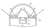
- FIG. 4 is a cross-sectional view of the vicinity of the imaging unit and the illumination unit of the capsule endoscope according to the second embodiment of the present invention.
- FIG. 5 is a diagram showing the wavelength dependence of the light absorption characteristic level of blood.
- FIG. 6 is a schematic diagram showing the relationship between the ingress and reflection of light with respect to the inner wall of the body cavity and the blood vessel.
- FIG. 7 is a block diagram showing a configuration of a capsule endoscope according to the second embodiment of the present invention.
- FIG. 8 is a flowchart showing an observation mode control processing procedure by the observation mode control unit in the capsule endoscope according to the second embodiment of the present invention.
- FIG. 9 is a timing chart showing an example of observation mode control processing by the observation mode control unit in the capsule endoscope according to the second embodiment of the present invention.
- FIG. 10 is a plan view of the vicinity of the imaging unit and the illumination unit of the capsule endoscope according to the third embodiment of the present invention.
- FIG. 11 is a cross-sectional view of the vicinity of an imaging unit and an illumination unit of a capsule endoscope according to Embodiment 3 of the present invention.
- FIG. 12 is a flowchart showing an observation mode control processing procedure by the observation mode control unit in the capsule endoscope according to the third embodiment of the present invention.
- FIG. 13 is a flowchart showing an observation mode control processing procedure by the observation mode control unit in the capsule endoscope according to the fourth embodiment of the present invention.
- FIG. 14 is a flowchart showing an observation mode control processing procedure by the observation mode control unit in the capsule endoscope according to the fifth embodiment of the present invention.
- FIG. 15 is a block diagram showing a configuration of a capsule endoscope according to the sixth embodiment of the present invention.
- FIG. 16 is a flowchart showing a light emission amount adjustment processing procedure by the light emission amount adjustment unit shown in FIG. FIG.
- FIG. 17 is a flowchart showing a light emission amount adjustment processing procedure by the light emission amount adjustment unit of the capsule endoscope according to the seventh embodiment of the present invention.
- FIG. 18 is a block diagram showing a configuration of a receiving apparatus according to Embodiment 8 of the present invention.
- FIG. 19 is a flowchart showing a brightness adjustment processing procedure by the brightness adjustment unit shown in FIG.
- FIG. 20 is a block diagram showing a configuration of a capsule endoscope according to the ninth embodiment of the present invention.
- FIG. 21 is a flowchart showing a schematic operation of the capsule endoscope according to the ninth embodiment of the present invention.
- FIG. 22 is a flowchart showing a schematic operation of the receiving apparatus 3 according to the ninth embodiment of the present invention.
- FIG. 23 is a flowchart showing a schematic operation of the image display device 4 according to the tenth embodiment of the present invention.
- FIG. 24 is a flowchart showing a schematic operation of an example (motion detection function) of the image processing function executed by the image display device in the tenth embodiment of the present invention.
- FIG. 25 is a flowchart showing a schematic operation of another example (red detection function) of the image processing function executed by the image display device in Embodiment 10 of the present invention.
- FIG. 26 is a block diagram showing a configuration of a capsule endoscope according to the eleventh embodiment of the present invention.
- FIG. 27 is a flowchart showing a schematic operation of the capsule endoscope according to the eleventh embodiment of the present invention.
- FIG. 28 is a flowchart showing a schematic operation of the receiving apparatus according to the eleventh embodiment of the present invention.
- FIG. 29 is a flowchart showing a schematic operation of the image display apparatus according to Embodiment 11 of the present invention.
- FIG. 1 is a block diagram showing a schematic configuration of an image processing system according to this embodiment.
- the image processing system 100 according to this embodiment roughly includes an image generation unit 101, a display unit 102, a brightness detection unit 106, and a control unit 107.
- the image generation means 101 has at least two observation modes for generating different types of images, for example, images composed of combinations of color components (for example, a normal light image and a special light image described later) alternately or continuously, This is means for selecting one of the observation modes and generating an image under the observation mode.
- the image generation unit 101 includes an imaging unit 103 that images a subject, an illumination unit 104 that illuminates the subject at the time of imaging, and an image processing unit 105 that performs predetermined image processing on image data obtained by imaging. .
- the brightness detection unit 106 detects information (hereinafter simply referred to as brightness information) indicating the brightness of an image obtained by the imaging unit 104 by imaging in one observation mode.
- the control means 107 controls the image generation means by controlling at least one of the imaging means 103, the illumination means 104, and the image processing means 105 of the image generation means 101 based on the brightness information detected by the brightness detection means 106. 101 controls the generation of an image in the other observation mode.
- the brightness information in this embodiment includes, for example, the exposure time when the imaging unit 103 captures images, the average luminance of the image acquired by the imaging unit 103, and a predetermined area of the image acquired by the imaging unit 103.
- Any information indicating the brightness of the image such as an integrated value (also referred to as exposure amount) of the signal intensity of the pixel to be used, can be used as the brightness information.
- the control unit 107 determines, for example, the light emission amount (power) and the light emission time of the illumination unit 104, and selects the type of light source to be driven. Control. Also, the control means 107 determines the exposure time by the image pickup means 103 based on the detected brightness information, and the pixel type (one or more of R, G, B) from which the image signal is read out. Make selections and other controls. Further, the control means 107 performs control for changing various parameters in the image processing by the image processing means 105 and selecting an image processing function to be executed based on the detected brightness information.
- the imaging unit 103, the illuminating unit 104, and the image processing unit 105 in the image generation unit 101 are controlled based on the acquired brightness information of the image, and an appropriate value according to the brightness of the image. Since the control is performed, it is possible to stably generate the image data itself and process the generated image data.
- Embodiment 2 a capsule endoscope system using a capsule endoscope as an imaging device will be described as an example.
- the capsule endoscope system according to this embodiment is a more specific example of the image processing system according to the first embodiment described above, and the concept is included in the concept of the image processing system.
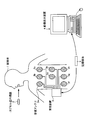
- FIG. 2 is a schematic diagram showing a configuration of a capsule endoscope system according to the second embodiment of the present invention.
- the capsule endoscope system according to the second embodiment includes a capsule endoscope 2 as an imaging device that captures an in-vivo image of a subject 1, and a capsule endoscope 2.
- a portable recording medium 5 for performing the above.
- the capsule endoscope 2 has an imaging function and a wireless communication function inside a capsule-type casing.
- the capsule endoscope 2 is introduced into an organ of the subject 1 by oral ingestion or the like, and then moves inside the organ of the subject 1 by a peristaltic motion or the like while being moved at a predetermined interval (for example, an interval of 0.5 seconds). Then, in-vivo images of the subject 1 are sequentially taken. Specifically, the capsule endoscope 2 performs normal image capturing using white light (ordinary light observation) and a clear blood vessel image of the inner wall of a body cavity with special blue and green color components. Imaging of a spectral image generated using light (special light observation) is alternately performed including a plurality of repetitions.
- the capsule endoscope 2 wirelessly transmits an image signal of the in-vivo image of the subject 1 thus imaged to the external receiving device 3.
- the capsule endoscope 2 sequentially repeats the in-vivo image capturing operation and the wireless transmission operation during a period from introduction into the organ of the subject 1 to discharge to the outside of the subject 1.
- the receiving device 3 includes, for example, a plurality of receiving antennas 3a to 3h distributed on the body surface of the subject 1, and a capsule inside the subject 1 via at least one of the plurality of receiving antennas 3a to 3h.
- a radio signal from the mold endoscope 2 is received.
- the receiving device 3 extracts an image signal from the radio signal from the capsule endoscope 2 and acquires in-vivo image data included in the extracted image signal.
- the receiving device 3 performs various image processing on the acquired image data, and accumulates the in-vivo image group subjected to the image processing in the recording medium 5 inserted in advance.
- the receiving device 3 associates time data such as an imaging time or a reception time with each image in the in-vivo image group.
- the receiving antennas 3a to 3h of the receiving device 3 may be arranged on the body surface of the subject 1 as shown in FIG. 2, or may be arranged on a jacket worn by the subject 1. Further, the number of receiving antennas of the receiving device 3 may be one or more, and is not particularly limited to eight.
- the image display device 4 has a configuration like a workstation that captures various data such as the in-vivo image group of the subject 1 via the recording medium 5 and displays the various data such as the captured in-vivo image group. Specifically, the image display device 4 is inserted with the recording medium 5 removed from the receiving device 3 and takes in the data stored in the recording medium 5 to obtain various data such as the in-vivo image group of the subject 1. get.
- the image display device 4 has a function of displaying the acquired in-vivo image on the display. Diagnosis and the like are performed by image display by the image display device 4.
- the recording medium 5 is a portable recording medium for transferring data between the receiving device 3 and the image display device 4 described above.
- the recording medium 5 is detachable from the receiving device 3 and the image display device 4 and has a structure capable of outputting and recording data when inserted into both. Specifically, when the recording medium 5 is inserted into the receiving device 3, the in-vivo image group subjected to image processing by the receiving device 3 and time data of each image are recorded.
- the capsule endoscope 2 has various functions built in the capsule casing 21, one end is covered with the dome-shaped transparent cover 20, and an illumination unit and an imaging unit are disposed on the one end side.
- a lens barrel 24 is provided at the center of a circle of a disk-shaped substrate 23, and an optical lens 13 in which the cylindrical axis of the capsule-shaped casing 21 serves as an optical axis.
- the image pick-up element 14 is provided.
- normal light sources 10a to 10c 10a to 10c (10) realized by white LEDs emitting white light, light in a wavelength band having a peak near 415 nm (blue), and near 540 nm (green)
- Special light sources 11a to 11c (11) that emit light in a wavelength band having a peak are arranged in an annular shape at different positions.
- the special light source 11 is a two-wavelength light emitting type in which a phosphor emitting 540 nm is applied to an LED chip emitting 415 nm.
- the light sources 10 and 11 have substantially the same light distribution characteristics.
- a transparent fixing member 12 is provided above the light sources 10 and 11.
- the image sensor 14 is realized by a normal Bayer array CCD or the like.
- the light absorption characteristic level of blood is low except that there is a peak L1 at 415 nm (blue) and a peak at 540 nm (green).
- the light absorption characteristic level of blood is low except that there is a peak L1 at 415 nm (blue) and a peak at 540 nm (green).
- FIG. 6 on the inner wall of the body cavity, capillaries 43 are present in the mucosal surface layer 40, and thick blood vessels 44 are present in the deep mucosa 41.
- the 415 nm (blue) light 30 ⁇ / b> B irradiated to the inner wall of the body cavity has a short wavelength, and therefore does not pass through the inside of the tissue, but is absorbed by the capillary blood vessels 43 due to the above-described blood absorption characteristics.
- the light 530 nm (green) 30G has a wavelength longer than that of blue, the light 30G is transmitted to the deep mucosa 41 and is absorbed by the thick blood vessel 44 due to the above-described blood absorption characteristics.
- the red light 30R is transmitted to the internal tissue 42 and is mostly reflected as scattered light. Therefore, if the light receiving sensitivity of only 415 nm (blue) and 540 nm (green) is provided, contrast information of blood vessel images such as the capillary blood vessels 43 and the thick blood vessels 44 can be obtained.
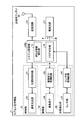
- FIG. 7 is a block diagram showing a detailed configuration of the capsule endoscope 2.
- the capsule endoscope 2 detects an illumination unit 51 that emits illumination light of a subject, an imaging unit 52 that receives reflected light from the subject and images the subject, and detects whether the capsule is inside or outside
- a power supply circuit 57 that supplies power to various components under the control of the system control unit 54.
- the illumination unit 51 includes the above-described normal light source 10, special light source 11, and a light source control circuit 61 that performs drive control of the normal light source 10 and the special light source 11.
- the special light source 11 emits special light having a light amount smaller than that of the normal light when the current supplied to the normal light source 10 is the same.
- the imaging unit 52 includes the above-described imaging element 14 and an imaging element control circuit 62 that controls driving of the imaging element 14.
- the state detection unit 53 includes a sensor unit 63 and a sensor unit control circuit 64 that drives and controls the sensor unit 63.
- the sensor unit 63 can detect at least whether the capsule endoscope 2 is in a liquid such as water in the subject 1 (whether it is in a liquid or in a gas). This is realized by various sensors.
- the system control unit 54 includes an exposure time measurement unit 71 and an observation mode control unit 72.
- the exposure time measurement unit 71 measures at least the exposure time during normal light observation as brightness information.
- the observation mode control unit 72 based on the exposure time information measured by the exposure time measurement unit 71, the normal light observation mode corresponding to the first observation mode for capturing the normal light image, and the special light image. The operation with the special light observation mode corresponding to the second imaging mode for performing imaging is controlled.
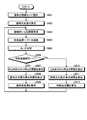
- the observation mode control unit 72 first emits normal light having a preset light amount from the normal light source 10 (step S101). Thereafter, the normal light image is captured and acquired by the imaging unit 52 (step S102). Then, the normal light image is transmitted to the receiving device 3 outside the subject via the transmitting circuit 55 and the transmitting antenna 56 (step S103). Thereafter, it is determined whether or not the special light observation mode is set (step S104). When it is not the special light observation mode (step S104, No), the process proceeds to step S201, and the normal light observation mode is continued.
- step S104 if the special light observation mode is selected (step S104, Yes), it is further determined whether or not the exposure time of the normal light is continuously greater than or equal to the specified value based on the measurement result of the exposure time measurement unit 71. Judgment is made (step S105). When it is continuously the specified value or more (step S105, Yes), the process proceeds to step S101, and normal light observation is performed while maintaining the normal light observation mode.
- Step S106 the special light source 11 is caused to emit light (Step S106), and the process proceeds to Step S102 and the special light image is obtained by the imaging unit 52. To capture and acquire. That is, the operation in the special light observation mode is performed.
- the observation mode control unit 72 performs special light observation in a preset alternating sequence, and when the exposure time at the previous and previous normal light observations is both equal to or greater than a specified value, in other words, When there is little reflected light, the amount of reflected light is small even if special light observation is performed, so a special light image with sufficient brightness cannot be obtained, so normal light observation should be performed instead of this special light observation. ing.
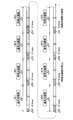
- FIG. 9 is a timing chart showing specific observation mode operation control by the observation mode control unit 72.
- FIG. 9 shows a case where normal light observation and special light observation are performed at the time interval ⁇ T1.
- the time ⁇ t2 is an exposure time
- the time ⁇ t3 is a specified value
- the time tmax is a maximum exposure time setting value.
- normal light observation and special light observation are performed as follows: normal light observation M11 ⁇ special light observation M21 ⁇ normal light observation M12 ⁇ special light observation M22 ⁇ normal light observation M13. And are performed alternately.
- the exposure time ⁇ t2 of the normal light observations M12 and M13 is both equal to or greater than the specified value ⁇ t3 and continuously equal to or greater than the specified value ⁇ t3.
- the normal light observation M14 is performed instead of the special light observation during the special light observation time.
- the normal light observation M15 is performed.
- the special light observation M23 is performed because it does not exceed the specified value ⁇ t3.
- normal light observation always performs normal light observation in alternating time zones, but special light observation is performed immediately after the exposure time during normal light observation continuously exceeds the specified value. Normal light observation is performed without performing special light observation. As a result, a normal light image with sufficient brightness can be obtained instead of a special light image without sufficient brightness, and the power can be used efficiently.
- Embodiment 3 As an image processing system according to Embodiment 3 of the present invention, a capsule endoscope system using a capsule endoscope as an imaging device will be described as an example.
- the capsule endoscope system according to this embodiment is a more specific example of the image processing system according to the first embodiment described above, similar to the capsule endoscope system according to the second embodiment.
- the concept is included in the concept of the image processing system.
- the special light source 11 is divided into a wide directivity special light source 111 (111a to 111c) having a wide directivity with respect to the optical axis of the image sensor 14 and a narrow directivity special light having a narrow directivity.
- Each pair includes a light source 112 (112a to 112c).
- the wide directivity special light source 111 and the narrow directivity special light source 112 are both arranged in an annular shape, but the wide directivity special light source 111 is narrow. It is arranged on the inner periphery of the directional special light source 112.
- the narrow directivity special light source 112 By arranging the narrow directivity special light source 112 on the inner periphery of the wide directivity special light source 111, it is possible to prevent the light of the wide directivity special light source 111 from directly entering the image sensor 14. A flat light can be irradiated over a wide band.
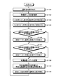
- FIG. 12 is a flowchart showing an observation mode control processing procedure by the observation mode control unit according to Embodiment 3 of the present invention.
- the observation mode control unit 72 performs the same processing as steps S101 to S105 shown in FIG. 8, and in step S205 corresponding to step 105, the normal light exposure time continuously becomes a specified value or more. It is determined whether or not.
- Step S205 when the exposure time of normal light is not continuously longer than the specified value (No at Step S205), the narrow directivity special light source 112 and the wide directivity special light source 111 are caused to emit light (Step S206), and Step S202.
- the special light observation mode operation is performed by moving to.
- step S207 determines whether the capsule endoscope 2 is in the liquid based on the detection result of the sensor unit 63. It is determined whether or not (step S207).
- the capsule endoscope 2 is not in the liquid (No at Step S207)
- the capsule endoscope 2 is in the gas
- the process proceeds to Step S201, and normal light observation is performed during this special light observation period. Let it be done.
- step S207, Yes only the wide directivity special light source 111 is caused to emit light (step S208), and the process proceeds to step S202 to perform special light observation. In this case, since light having a wide directivity is irradiated, a special light image can be obtained for a subject in the vicinity of the capsule endoscope 2.
- the observation mode control unit 72 performs the process of performing special light observation or replacing with normal light observation without performing special light observation. For example, as shown in FIG. 14, after the determination processing in step S405 corresponding to step S305, when the amount of normal light emission is continuously equal to or greater than the specified value, the special light sources 11, 111, 112 are used. Special light observation is performed after increasing the amount of emitted light (step S406). If the amount of emitted normal light is not continuously greater than or equal to the specified value (step S405, No), the special light source 11, 111, 112 is used. After returning the light emission amount to the initial value (step S407), special light observation is performed. By performing such light emission amount control, it is possible to perform observation while suppressing the power consumption of special light observation.
- Embodiment 6 As an image processing system according to Embodiment 6 of the present invention, a capsule endoscope system using a capsule endoscope as an imaging device will be described as an example. Note that the capsule endoscope system according to this embodiment is more specific to the above-described image processing system according to the first embodiment, like the capsule endoscope system according to any of the second to fifth embodiments. The concept is included in the concept of the image processing system.
- the light emission amounts of the normal light source 10 and the special light source 11 are individually adjusted for the imaging of the normal light image and the special light image.
- the capsule endoscope 2 includes a system control unit 54 that makes the brightness of each acquired image appropriate.
- the system control unit 54 includes a light emission amount adjustment unit 171 that adjusts the light emission amount of the normal light source 10 and the special light source 11 corresponding to each of the acquired normal light image and special light image.
- the system control unit 54 includes an observation mode control unit 172 that performs mode control such as switching between observation modes for capturing a normal light image and a special light image.
- the light emission amount adjustment unit 171 determines whether the currently captured image is a normal light image based on the control content of the observation mode control unit 172 (step S501). When the image is a normal light image (step S501, Yes), the light emission amount adjustment unit 171 integrates the values of all pixels (R, G, B) within a predetermined range of the normal light image acquired last time (step S502). ). Thereafter, it is determined whether or not the integrated value is an image having an appropriate range, that is, an appropriate brightness (step S503).
- step S503 No If the integrated value is not within the proper range (step S503, No), the light emission amount of the normal light source 10 is adjusted so that the brightness of the image is within the proper range (step S504), and the process proceeds to step S508. On the other hand, when the integrated value is within the appropriate range (step S503, Yes), the process proceeds to step S508 as it is in order to maintain the light emission amount of the normal light source 10 currently set.
- step S501, No the green (G) pixel and the blue (B) pixel within the predetermined range of the special light image acquired last time are integrated (step S505). Thereafter, it is determined whether or not the integrated value is within an appropriate range (step S506). If the integrated value is not within the proper range (step S506, No), the light emission amount of the special light source 11 is adjusted so that the brightness of the image is within the proper range (step S507), and the process proceeds to step S508. If the integrated value is within the appropriate range (step S506, Yes), the process proceeds to step S508 as it is. Thereafter, in step S508, it is determined whether or not the light emission amount adjustment process is completed. If not completed (No in step S508), the above-described process is repeated, and if completed (step S508, Yes), This process ends.
- each image can be acquired as an image having appropriate brightness. it can.
- the light emission amount adjustment for the normal light source 10 and the special light source 11 is performed.
- the present invention is not limited to this, and the exposure time adjustment is performed for each normal light image and special light image. You may do it.
- Embodiment 7 As an image processing system according to Embodiment 7 of the present invention, a capsule endoscope system using a capsule endoscope as an imaging device will be described as an example.
- the capsule endoscope system according to this embodiment is more specific to the above-described image processing system according to the first embodiment, like the capsule endoscope system according to any one of the second to sixth embodiments.
- the concept is included in the concept of the image processing system.
- the luminance is calculated as the brightness information based on the calculation formulas corresponding to the characteristics of each image output, and the normal light
- the light emission amount of the light source 10 and the special light source 11 is adjusted.
- step S603 it is determined whether or not the average luminance YW is an image having an appropriate range, that is, an appropriate brightness (step S603). If the average luminance YW is not in the appropriate range (No in step S603), the light emission amount of the normal light source 10 is adjusted so that the brightness of the image is within the appropriate range (step S604), and the process proceeds to step S608. . On the other hand, when the average luminance YW is within the appropriate range (step S603, Yes), the process proceeds to step S608 as it is to maintain the currently set light emission amount of the normal light source 10.
- the average luminance is expressed by the following equation based on the values of green (G) pixels and blue (B) pixels within a predetermined range of the special light image acquired last time. Calculation is performed according to (2) (step S605).
- YN 0.30 ⁇ G + 0.70 ⁇ B (2)
- This equation (2) is a calculation equation applied when a red (R) pixel is output as a green (G) pixel and a blue (B) pixel is output as a blue (B) pixel.
- step S606 it is determined whether or not the average luminance YN is within an appropriate range.
- the average luminance YN is not in the proper range (No in step S606)
- the light emission amount of the special light source 11 is adjusted so that the brightness of the image is within the proper range (step S607), and the process proceeds to step S608.
- the process proceeds to step S608 as it is.
- step S608 it is determined whether or not the light emission amount adjustment processing is finished. If it is not finished (step S608, No), the above-described processing is repeated, and if it is finished (step S608, Yes), This process ends.
- the appropriate range of step S603, S606 may be the same, and may differ.
- the average brightness is calculated individually for each of the normal light image and the special light image using different average brightness calculation formulas, and the light emission amount is adjusted based on the average brightness. Therefore, each image can be acquired as an image having appropriate brightness.
- the eighth embodiment is characterized in that the brightness of each image data is adjusted by performing amplification processing of pixel data corresponding to each of the received normal light image and special light image.
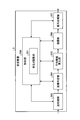
- FIG. 18 is a block diagram showing a configuration related to image processing of the receiving apparatus 3 according to the eighth embodiment of the present invention. As shown in FIG. 18, the receiving device 3 performs preprocessing on data D converted from a radio signal wirelessly transmitted from the capsule endoscope 2 to a baseband signal, and outputs RGB color data.
- the preprocessing circuit 203, the image determination unit 204 for determining whether the image processed by the preprocessing unit 203 is a normal light image or a special light image, and the determination result of the image determination unit 204 An average luminance calculation unit 205 that calculates an average luminance of a predetermined range, an amplification unit 206 that amplifies or attenuates each image data based on the calculation result of the average luminance calculation unit 205, and an image processed by the amplification unit 206, A signal processing unit 207 that performs predetermined signal processing and outputs the signal to the outside.
- the receiving apparatus 3 also includes a control unit 200 that controls the preprocessing unit 203, the image determination unit 204, the average luminance calculation unit 205, the amplification unit 206, and the signal processing unit 207. Furthermore, the control unit 200 includes a brightness adjustment unit 201. The brightness adjustment unit 201 controls amplification processing by the amplification unit 206 based on the processing results of the image determination unit 204 and the average luminance calculation unit 205. Adjust the image brightness.
- the brightness adjustment unit 201 determines whether the input image is a normal light image based on the determination result of the image determination unit 204 (step S701). When the image is not a normal light image (No in step S701), the brightness adjustment unit 201 causes the average luminance calculation unit 205 to calculate the average luminance of all pixels within the predetermined range of the special light image (step S702).
- step S703 it is determined whether or not the calculated average luminance is within an appropriate range.
- step S703 the amplification factor of the pixel data by the amplifying unit 206 is changed so that the brightness of the special light image is within the appropriate range, and the appropriate brightness is set.
- the special light image including the pixel data is output to the signal processing unit 207 (step S704), and the process proceeds to step S705.
- step S703 if the average luminance is within the appropriate range (step S703, Yes), each pixel data is not amplified and output to the signal processing unit 207 as it is, and the process proceeds to step S705.
- step S701 if the image is a normal light image (step S701, Yes), the process proceeds to step S705 as it is. After that, in step S705, it is determined whether or not the brightness adjustment process is finished. Only when it is not finished (step S705, No), the above-described process is repeated, and when it is finished (step S705, Yes), This process ends.
- pixel data amplification processing corresponding to the type of the acquired image that is, the normal light image and the special light image is performed, so that an image having appropriate brightness is acquired. be able to.
- the brightness adjustment unit 201 may further amplify by the signal processing unit 207 based on the calculation result of the average luminance.
- the amplification unit 204 is not limited to amplification, and may perform attenuation processing.
- the processing in the receiving device 3 has been described.
- the present invention is not limited to this, and the same amplification processing as in the receiving device 3 may be performed on the image display device 4 side.
- the amplification process may be performed on the capsule endoscope 2 side.
- the capsule endoscope 2 has been described as an example. After the capsule endoscope 2 is introduced into the subject, the operation of the observation mode must be controlled independently by the capsule endoscope 2 itself, which is suitable for application of the present invention. .
- the capsule endoscope 2 determines the light emission time of the normal light source 10 or the special light source 11 in the next imaging based on the brightness of the image data obtained by the previous imaging. Further, the image data obtained by this imaging is transmitted from the transmission circuit 55 to the reception device 3 outside the subject 1 as a radio signal via the transmission antenna 56.
- the receiving device 3 records the image data received from the capsule endoscope 2 on, for example, a portable recording medium 5. At this time, the receiving apparatus 3 operates so as not to store an image with extremely low brightness and an image with extremely high brightness. As a result, an image that is not effective for interpretation within the subject 1, such as an underexposed image that is entirely dark and blurred, or an overexposed image that is entirely white (not included in the allowable range described later) Image) can be discarded.
- the capsule endoscope system according to the ninth embodiment is the same as any one of the above-described embodiments.
- the exposure time measurement unit 71 in the system control unit 54 of the capsule endoscope 2 is replaced with a brightness information detection unit 71A.
- the brightness information detection unit 71A detects, for example, a value (also referred to as an exposure amount) obtained by integrating the signal intensity of pixels in a predetermined area in the image signal read from the image sensor 14 as brightness information.
- FIG. 20 is a block diagram showing the configuration of the capsule endoscope according to the ninth embodiment.
- FIG. 21 is a flowchart showing a schematic operation of the capsule endoscope according to the ninth embodiment.
- FIG. 22 is a flowchart showing a schematic operation of the receiving apparatus 3 according to the ninth embodiment. The operation shown in FIG. 21 is repeated until the battery in the capsule endoscope 2 runs out.
- the capsule endoscope 2 As shown in FIG. 21, after the capsule endoscope 2 is activated, first, the normal light observation mode is selected (step S901), and the normal light source 10 is emitted (step S902). Subsequently, the capsule endoscope 2 drives the imaging unit 52 to acquire image data (step S903), and transmits the acquired image data to the receiving device 3 by a wireless signal (step S904).
- the capsule endoscope 2 switches the imaging mode to either the normal light observation mode or the special light observation mode (step S905). For example, when the current imaging mode is the normal light observation mode, the observation mode is switched to the special light observation mode. When the current imaging mode is the special light observation mode, the normal light observation mode is switched. Subsequently, the capsule endoscope 2 determines whether or not the observation mode after switching, that is, the observation mode at the next imaging is the special light observation mode (step S906).
- step S906 when the current observation mode is the normal light observation mode (No in step S906), the capsule endoscope 2 uses the R component, the G component, and the B component in the previously acquired normal light image. The brightness information of the image is detected from all the components (step S907). Subsequently, the capsule endoscope 2 calculates the light emission time of the normal light source 10 from the detected brightness information (step S908), and emits the normal light source 10 with the calculated light emission time (step S909). Return to step S903. When the emission time calculated in step S908 is longer than the maximum value of the emission time set as the upper limit in advance, the capsule endoscope 2 emits the normal photoantigen 10 with, for example, this maximum emission time. .
- step S906 determines whether the current observation mode is the special light observation mode (Yes in step S906).
- the capsule endoscope 2 uses the G component in the normal light image or special light image acquired immediately before.
- B component that is, brightness information of the image is detected from the color component forming the special light image (step S910), and the emission time of the special light source 11 is calculated from the detected brightness information (step S911).
- the process returns to step S903.
- the emission time calculated in step S912 is larger than the maximum value of the emission time set as the upper limit in advance, the capsule endoscope 2 emits the normal photoantigen 10 with the emission time of the maximum value, for example. .
- the receiving device 3 waits to receive image data from the capsule endoscope 2 (No in steps S921 and S921).
- the receiving device 3 determines whether or not the received image is a special light image (step S922). If the received image is not a special light image, that is, a normal light image (No in step S922), the receiving device 3 acquires an allowable brightness range for the normal light image (step S923). On the other hand, when the received image is a special light image (Yes in step S922), the receiving device 3 acquires an allowable brightness range for the special light image (step S924).
- the allowable brightness range for the normal light image and the allowable brightness range for the special light image can be realized by, for example, setting an upper limit value and a lower limit value of each range in advance.
- Each upper limit value and lower limit value are stored in advance in, for example, a memory (not shown) in the receiving device 3.
- the receiving device 3 derives the brightness information of the image from the pixel values of the pixels included in the predetermined area of the target image (step S925), and the brightness of the image specified from the brightness information is determined. It is determined whether it is included in the allowable range specified in step S923 or S924 (step S926). As a result of the determination in step S926, when the brightness of the target image is within the allowable range (Yes in step S926), the receiving device 3 executes image processing such as synchronization processing and compression processing on the target image (step S926). In step S927, the image data after image processing is stored in the recording medium 5 (step S928). On the other hand, when the brightness of the target image is not within the allowable range (No in step S926), the receiving device 3 discards the target image data (step S929).
- the receiving device 3 determines whether or not an instruction to end the operation has been input from, for example, the user (step S930). If the end instruction has been input (Yes in step S930), the operation illustrated in FIG. 22 is performed. finish. On the other hand, when the termination instruction has not been input (No in step S930), the reception device 3 returns to step S921 and executes the subsequent operations.
- a capsule endoscope system using a capsule endoscope as an imaging device will be described as an example.
- the capsule endoscope system according to this embodiment is more specific to the above-described image processing system according to the first embodiment, similar to the capsule endoscope system according to any of the second to ninth embodiments.
- the concept is included in the concept of the image processing system.
- the capsule endoscope 2 determines the light emission time of the normal light source 10 or the special light source 11 in the next imaging based on the brightness of the image data obtained by the previous imaging. Further, the image data obtained by this imaging is transmitted from the transmission circuit 55 to the receiving device 3 outside the subject 1 as a radio signal via the transmitting antenna 56 and stored in a predetermined storage (for example, the recording medium 5). Is done. The stored image data is loaded into the image display device 4 via a communication interface (for example, USB or LAN) that connects the cradle and the image display device 4 when the receiving device 3 is connected to a cradle (not shown), for example.
- a communication interface for example, USB or LAN
- the image display device 4 has a motion detection function for detecting the motion of the image (and movement of the capsule endoscope 2 predicted from the change of the image) with respect to the input image data, and a red portion in the image.
- An image processing function such as a red detection function for detecting whether or not there is a red area in the image is executed.
- the motion detection function calculates a scalar amount (however, an absolute value) of a motion vector between images before and after, and when this scalar amount is larger than a preset threshold value, an image to be displayed, that is, an image to be interpreted.
- a target image For example, images that are not displayed are stocked in a predetermined storage area while maintaining time-series information for the preceding and following images.
- a large scalar amount for example, when the imaging window of the capsule endoscope 2 is directed toward the sky from the state of being close to the body tissue (hereinafter referred to as a first case)
- a second case There is a case where the observation window is in the sky direction and contacts the body tissue (hereinafter referred to as a second case).
- the imaging window In a state where the imaging window is close to the body tissue, it is possible to brightly capture the subject (internal tissue) with a small amount of illumination light. For this reason, in the first case, one or several images captured immediately after the observation window faces the sky are dark images that are underexposed.
- This dark image is an image that is not suitable for interpretation, but has a large motion vector relative to the image when the observation window captured immediately before is close to the body tissue, so that the scalar amount is a large value. Become. As a result, this dark image is selected as a display target image.
- the imaging window faces the sky, the distance between the imaging unit and the subject is long, and a bright image cannot be obtained unless illuminated with a large amount of illumination light. For this reason, in the second case, one or several images captured immediately after the observation window comes close to the body tissue are overexposed images.
- This too bright image is not suitable for image interpretation, but has a large motion vector with respect to the image when the observation window captured immediately before is facing the sky, so that the scalar amount is a large value. . As a result, this too bright image is selected as a display target image.
- whether or not to select the target image as a display target is determined based on the brightness information of each image in addition to the scalar quantity of the motion vector between the preceding and following images. Therefore, it is possible to prevent a dark image or an excessively bright image that is not suitable for interpretation from being selected as a display target.
- the red detection function may cause the algorithm to malfunction for images with insufficient or excessive brightness. This is because, in a dark image, the white balance of the image changes depending on the degree of brightness, such as the R component (red component) becomes dominant over the other components (G, B component).
- the red detection function that detects an image with a strong red color (an image containing many red areas, an image with a strong R component, etc.) by an algorithm based on the relative value of each color component is used when the white balance of the image is lost.
- the image in which the image is broken may be evaluated differently from the color of the real space. As a result, even if red is strong in real space, the image taken is evaluated as a strong red image, or even if red is not strong in real space, the image taken is red. May be evaluated as a strong image.
- this embodiment it is configured such that red detection is performed only on an image having a certain degree of uniform brightness. As a result, it is possible to avoid red detection from being performed on an image whose white balance has been greatly lost, so that the operation of the red detection function can be stabilized.
- FIG. 23 is a flowchart showing a schematic operation of the image display device 4 according to the tenth embodiment.
- FIG. 24 is a flowchart showing a schematic operation of an example (motion detection function) of an image processing function executed by the image display apparatus in the tenth embodiment.
- FIG. 25 is a flowchart showing a schematic operation of another example (red detection function) of the image processing function executed by the image display device in the tenth embodiment.
- the image display device 4 waits for input of image data from the receiving device 3 via the cradle (No in steps S1001 and S1001), and when the image data is input (step S1001). Yes), an image processing function for the image data is executed (step S1002).
- the image data input in step S1001 is not limited to one image data, and may be a group of image data arranged in time series, for example.
- the image processing function executed in step S1002 includes, for example, a motion detection function and a red detection function.
- the image display device 4 executes an image display process for displaying an image processed using the image processing function (step S1003), thereby causing the user to interpret the in-subject image. Thereafter, the image display device 4 determines whether or not an instruction to end the main operation is input from the user (step S1004), and if it is input (Yes in step S1004), the main operation is ended. On the other hand, if the end instruction has not been input (No in step S1004), the image display device 4 returns to step S1001 and executes the subsequent operations.
- the process is not limited to step S1001, and may be returned to step S1002 or S1003.
- step S1011 the image display device 4 selects one of the input image data (step S1011), and detects brightness information of this image (step S1011). S1012).
- the selection of image data is, for example, in the order of time series when the image data is arranged in time series.
- the image display device 4 determines whether or not the brightness of the target image is within a preset allowable range based on the detected brightness information of the image (step S1013). If not (No in step S1013), the target image data is set as image data not to be displayed (step S1017), and then the process proceeds to step S1018.
- the image display device 4 calculates a motion vector between the target image data and the immediately preceding image data in time series (Ste S1014). Subsequently, the image display device 4 determines whether or not the calculated scalar quantity (absolute value) of the motion vector is greater than or equal to a preset threshold value (step S1015). (No in step S1015), the target image data is set as image data that is not a display target (step S1017), and then the process proceeds to step S1018.
- the image display device 4 selects the target image as a display target image (step S1016).
- the selection of the display target image can be realized by attaching a flag indicating the display target to the image data or recording the display target image in a recording area such as another folder. .
- step S1018 determines whether or not the above processing has been executed for all input image data (step S1018), and if it has been executed (Yes in step S1018), FIG. Return to the operation shown in FIG. On the other hand, if there is image data that has not yet been processed (No in step S1018), the image display device 4 returns to step S1011 and executes the subsequent operations.
- a red detection function will be described as an example of the image processing function executed in step S1002 of FIG.
- the image display device 4 selects one of the input image data (step S1021), and detects the brightness information of this image (step S1021). S1022).
- the selection of image data is, for example, in the order of time series when the image data is arranged in time series.
- the image display device 4 determines whether or not the brightness of the target image is within a preset allowable range based on the detected brightness information of the image (step S1023). If not (No in step S1023), the target image data is not subject to red detection (step S1027), and then the process proceeds to step S1028.
- the image display device 4 uses the color evaluation function corresponding to the brightness information previously managed in a memory (not shown). A threshold is specified (step S1024), and red detection is performed on the target image using this threshold (step S1025). Further, the image display device 4 stores the detected result along the same time series as the time series of the image data (step S1026).
- the image display device 4 determines whether or not the above processing has been executed for all input image data (step S1028), and if there is image data that has not yet been processed (step S1028). No), the process returns to step S1021, and the subsequent operations are executed. On the other hand, if the processing for all the image data has been executed (Yes in step S1028), the image display device 4 generates a red bar image from the red detection results stored in time series in step S1026. Then, the operation shown in FIG. 23 is returned. Note that the red bar is a bar-shaped image that is visualized so that the red detection result of the image along the time series can be recognized at a glance.
- the image processing function operates based on the brightness of the image, it is possible to perform appropriate control according to the brightness of the image. Can be performed.
- the image display device 4 controls the operation based on whether or not the value of the brightness information is within a preset upper limit value and lower limit value (allowable range).
- a preset upper limit value and lower limit value allowable range
- the present invention is not limited to this, and various modifications can be made.
- red detection is performed using an image whose brightness information value is within the allowable range as a red detection target.
- the red detection function may be configured to change the threshold value of the color evaluation coefficient used for red detection according to the value of the brightness information. Thereby, it is possible to further improve the operation accuracy of the red detection function.
- the correspondence relationship between the threshold value of the color evaluation function and the brightness information may be previously managed in a table.
- the capsule endoscope 2 acquires a normal light image.
- the image thus obtained is input to the image display device 4 through the receiving device.
- the image display device 4 generates a special light image from the input normal light image using the G component and the B component.
- the image display device 4 executes predetermined image processing on the normal light image and the special light image, and displays the result and the image to the user.
- the G and B components may be insufficient on the other hand.
- the brightness of the normal light image is sufficient, but the brightness of the special light image generated from the normal light image is small. Therefore, in the present embodiment, illumination is performed so that the G and B components in the image obtained by the next imaging are large enough to generate the special light image based on the brightness of the image obtained by the previous imaging.
- the unit 51B is controlled. Thereby, it becomes possible to acquire a normal light image and a special light image from an image obtained by one imaging.
- FIG. 26 is a block diagram showing the configuration of the capsule endoscope according to the eleventh embodiment.
- FIG. 27 is a flowchart showing a schematic operation of the capsule endoscope according to the eleventh embodiment.
- FIG. 28 is a flowchart showing a schematic operation of the receiving apparatus according to the eleventh embodiment.
- FIG. 29 is a flowchart showing a schematic operation of the image display apparatus according to the eleventh embodiment. The operation shown in FIG. 27 is repeated until the battery in the capsule endoscope 2 runs out.
- the capsule endoscope 2 first emits the normal light source 10 (step S1101), and then drives the imaging unit 52 to acquire image data (step S1102). . Subsequently, the capsule endoscope 2 detects brightness information of the normal light image (hereinafter referred to as normal light image brightness information) from the R, G, and B components of the acquired image data (step S1103). Thus, the brightness information of the special light image (hereinafter referred to as special light image brightness information) is detected from the G and B components of the image data (step S1104).
- normal light image brightness information brightness information of the normal light image
- special light image brightness information hereinafter referred to as special light image brightness information
- the capsule endoscope 2 determines whether or not the value of the normal light image brightness information detected in step S1103 is within a preset allowable range (step S1105). (Yes in step S1105), a normal light image flag indicating that the image data is a normal light image effective for interpretation is attached to the image data (step S1106). On the other hand, when the value of the normal light image brightness information is not within the allowable range (No in step S1105), the capsule endoscope 2 proceeds to step S1107 as it is.
- the capsule endoscope 2 determines whether or not the value of the special light image brightness information detected in step S1104 is within a preset allowable range (step S1107). (Yes in step S1107), a special light image flag indicating that the image data is image data that can generate a special light image is attached to the image data (step S1108). On the other hand, when the value of the special light image brightness information is not within the allowable range (No in step S1107), the capsule endoscope 2 proceeds to step S1109 as it is. Note that instead of the normal light image flag and the special light image generation flag described above, the calculated normal light image brightness information and / or special light image brightness information may be attached to the image data.
- the capsule endoscope 2 transmits image data to the receiving device 3 (step S1109). Subsequently, the capsule endoscope 2 calculates the light emission time of the normal light source 10 in the next imaging from the special light image brightness information (step S1110), and emits the normal light source 10 with the calculated light emission time. (Step S1111). Thereafter, the capsule endoscope 2 returns to step S1102, and thereafter performs the same operation. If the light emission time calculated in step S1110 is longer than the maximum value of the light emission time set as the upper limit in advance, the capsule endoscope 2 emits the normal photoantigen 10 with the light emission time of this maximum value, for example. To do.
- the receiving device 3 waits to receive image data from the capsule endoscope 2 (No in steps S1121 and S1121).
- the receiving device 3 determines whether at least one of the normal light image flag and the special light image flag is attached to the received image data. (Step S1122), and if it is not attached (No in Step S1122), the image data is discarded without being saved (Step S1125).
- step S1122 when the special light image generation flag is attached to the image data (Yes in step S1122), the receiving device 3 executes predetermined image processing such as synchronization processing and compression processing on the image data (In step S1123), the image data after image processing is stored in the recording medium 5 (step S1124).
- predetermined image processing such as synchronization processing and compression processing
- the receiving apparatus 3 determines whether or not an instruction to end the operation has been input from the user (step S1126), and if the end instruction has been input (Yes in step S1126), the operation illustrated in FIG. 28 is performed. finish. On the other hand, when the end instruction has not been input (No in step S1126), the receiving apparatus 3 returns to step S1121 and executes the subsequent operations.
- the image display device 4 waits for input of image data from the receiving device 3 via the cradle (No in steps S1131 and S1131), and when the image data is input (step S1131). Yes), one of the input image data is selected (step S1132), and it is determined whether or not a special light image flag is attached to the image data (step S1133). As a result of the determination in step S1133, when the special light image flag is not attached to the image data (No in step S1133), the image display device 4 proceeds to step S1135 as it is. On the other hand, when the special light image flag is attached to the image data (Yes in step S1133), the image display device 4 generates a special light image from the G and B components in the image data (step S1134), and step S1135. Migrate to
- step S1135 the image display device 4 stores the image data. Therefore, when the special light image is generated in step S1134 in addition to the normal light image, the image display device 4 stores the normal light image and the special light image in step S1135.
- the image display device 4 determines whether or not the above processing has been executed for all input image data (step S1136), and if there is image data that has not yet been processed (step S1136).
- the image display apparatus 4 returns to step S1132 and executes the subsequent operations.
- the image display device 4 determines whether an instruction to end the operation is input from the user, for example (step S1137). If it has been done (Yes in step S1137), this operation ends. On the other hand, if the end instruction has not been input (No in step S1137), the image display device 4 returns to step S1131 and executes the subsequent operations.
- the capsule endoscope 2 not only the capsule endoscope 2 but also the receiving device 3 and the image display device 4 are based on the information based on the brightness added to the image data by the capsule endoscope 2 ( Therefore, it is possible to stably generate the image data itself and process the generated image data.
- the brightness of the image acquired by the imaging unit 52 is adjusted by controlling the exposure time of the imaging unit 52 in accordance with the brightness of the image.
- the brightness of the image acquired by the imaging unit 52 is adjusted by controlling the illumination time of the illumination unit 51 according to the brightness of the image.
- the present invention is not limited to this, and in Embodiments 2 to 8, the brightness of the image acquired by the imaging unit 52 is adjusted by controlling the illumination time of the illumination unit 51 according to the brightness of the image.
- the brightness of the image acquired by the imaging unit 52 is adjusted by controlling the exposure time of the imaging unit 52 according to the brightness of the image. Since it is easy for those skilled in the art to perform various recombination partially, detailed description is omitted here.
- DESCRIPTION OF SYMBOLS 100 Image processing system 101 Image generation means 102 Display means 103 Illumination means 104 Imaging means 105 Image processing means 106 Brightness detection means 107 Control means 1 Subject 2 Capsule endoscope 3 Receiving device 3a-3h Receiving antenna 4 Image display device DESCRIPTION OF SYMBOLS 10,110 Normal light source 11 Special light source 12 Transparent cover 13 Optical lens 14 Image sensor 20 Dome type transparent cover 21 Capsule type housing 23 Substrate 40 Mucous membrane surface layer 41 Mucous membrane deep part 42 Internal tissue 43 Capillary blood vessel 44 Blood vessel 51 Illumination part 52 Imaging Unit 53 state detection unit 54, 54B system control unit 55 transmission circuit 56 antenna for transmission 57 power supply circuit 61 light source control circuit 62 imaging element control circuit 63 sensor unit 64 sensor unit control circuit 71 exposure time measurement unit 72, 172 observation Control unit 73 brightness information detection unit 74 flag addition unit 111 wide directivity special light source 112 narrow directivity special light source 171 light emission amount adjustment unit 201 brightness adjustment unit 203 pre
Abstract
Description
まず、この発明の実施の形態1によるカプセル内視鏡システムを説明するにあたり、カプセル型内視鏡システムの構築概念となる画像処理システムの構成を、図面を用いて詳細に説明する。図1は、この実施の形態による画像処理システムの概略構成を示すブロック図である。図1に示すように、この実施の形態による画像処理システム100は、大別して、画像生成手段101と表示手段102と明るさ検出手段106と制御手段107と、を備える。画像生成手段101は、異なる種類の画像、たとえば色成分の組合せよりなる画像(例えば後述する通常光画像と特殊光画像)を交互または連続して生成する少なくとも二つ以上の観察モードを有し、いずれか一方の観察モードを選択してその観察モード下で画像を生成する手段である。この画像生成手段101は、被写体を撮像する撮像手段103と、撮像時に被写体を照明する照明手段104と、撮像により得られた画像データに所定の画像処理を実行する画像処理手段105と、を備える。明るさ検出手段106は、撮像手段104が一方の観察モードでの撮像により得られた画像の明るさを示す情報(以下、単に明るさ情報という)を検出する。制御手段107は、明るさ検出手段106によって検出された明るさ情報に基づいて画像生成手段101の撮像手段103、照明手段104および画像処理手段105の少なくとも1つを制御することで、画像生成手段101による他方の観察モードでの画像の生成を制御する。 (Embodiment 1)
First, in describing the capsule endoscope system according to the first embodiment of the present invention, the configuration of an image processing system which is a concept of constructing a capsule endoscope system will be described in detail with reference to the drawings. FIG. 1 is a block diagram showing a schematic configuration of an image processing system according to this embodiment. As shown in FIG. 1, the
つぎに、この発明の実施の形態2による画像処理システムとして、撮像装置にカプセル型内視鏡を用いたカプセル型内視鏡システムを例に挙げて説明する。なお、この実施の形態によるカプセル型内視鏡システムは、上述した実施の形態1による画像処理システムをより具体化したものであり、その概念は当該画像処理システムの概念に含まれるものである。 (Embodiment 2)
Next, as an image processing system according to
つぎに、この発明の実施の形態3による画像処理システムとして、撮像装置にカプセル型内視鏡を用いたカプセル型内視鏡システムを例に挙げて説明する。なお、この実施の形態によるカプセル型内視鏡システムは、上記実施の形態2によるカプセル型内視鏡システムと同様、上述した実施の形態1による画像処理システムをより具体化したものであり、その概念は当該画像処理システムの概念に含まれるものである。 (Embodiment 3)
Next, as an image processing system according to
上述した実施の形態2,3では、いずれも露光時間測定部71が撮像部52の露光時間を測定することを前提して説明したが、これに限らず、通常光光源10,110の発光量を露光時間に対応づけて測定してもよい。この場合、観察モード制御部72は、図8に示したフローチャートのステップS105に替えて、図13のステップS305に示すように、通常光の発光量が連続して規定値以上であるか否かを判断すればよい。 (Embodiment 4)
In the above-described second and third embodiments, the description has been made on the assumption that the exposure time measurement unit 71 measures the exposure time of the
また、上述した実施の形態2~4では、観察モード制御部72が、特殊光観察を行うか、特殊光観察を行わずに通常光観察に置き換えるかの処理を行っていたが、これに限らず、たとえば、図14に示すように、ステップS305に対応するステップS405における判断処理の後、通常光の発光量が連続して規定値以上である場合には、特殊光光源11,111,112の発光量を増大させた(ステップS406)後に、特殊光観察を行い、通常光の発光量が連続して規定値以上でない場合(ステップS405,No)には、特殊光光源11,111,112の発光量を初期値に戻した(ステップS407)後、特殊光観察を行うようにする。このような発光量制御を行うことによって、特殊光観察の電力消費を抑えた観察を行うことができる。 (Embodiment 5)
In the second to fourth embodiments described above, the observation
つぎに、この発明の実施の形態6による画像処理システムとして、撮像装置にカプセル型内視鏡を用いたカプセル型内視鏡システムを例に挙げて説明する。なお、この実施の形態によるカプセル型内視鏡システムは、上記実施の形態2~5のいずれかによるカプセル型内視鏡システムと同様、上述した実施の形態1による画像処理システムをより具体化したものであり、その概念は当該画像処理システムの概念に含まれるものである。 (Embodiment 6)
Next, as an image processing system according to Embodiment 6 of the present invention, a capsule endoscope system using a capsule endoscope as an imaging device will be described as an example. Note that the capsule endoscope system according to this embodiment is more specific to the above-described image processing system according to the first embodiment, like the capsule endoscope system according to any of the second to fifth embodiments. The concept is included in the concept of the image processing system.
つぎに、この発明の実施の形態7による画像処理システムとして、撮像装置にカプセル型内視鏡を用いたカプセル型内視鏡システムを例に挙げて説明する。なお、この実施の形態によるカプセル型内視鏡システムは、上記実施の形態2~6のいずれかによるカプセル型内視鏡システムと同様、上述した実施の形態1による画像処理システムをより具体化したものであり、その概念は当該画像処理システムの概念に含まれるものである。 (Embodiment 7)
Next, as an image processing system according to Embodiment 7 of the present invention, a capsule endoscope system using a capsule endoscope as an imaging device will be described as an example. The capsule endoscope system according to this embodiment is more specific to the above-described image processing system according to the first embodiment, like the capsule endoscope system according to any one of the second to sixth embodiments. The concept is included in the concept of the image processing system.
YW=0.30×R+0.59×G+0.11×B …(1) The light emission
YW = 0.30 × R + 0.59 × G + 0.11 × B (1)
YN=0.30×G+0.70×B …(2)
なお、この式(2)は、赤(R)画素を緑(G)画素として出力し、青(B)画素を青(B)画素として出力する場合に適用される算出式である。 On the other hand, if the image is not a normal light image (No in step S601), the average luminance is expressed by the following equation based on the values of green (G) pixels and blue (B) pixels within a predetermined range of the special light image acquired last time. Calculation is performed according to (2) (step S605).
YN = 0.30 × G + 0.70 × B (2)
This equation (2) is a calculation equation applied when a red (R) pixel is output as a green (G) pixel and a blue (B) pixel is output as a blue (B) pixel.
つぎに、この発明の実施の形態8による画像処理システムとして、撮像装置にカプセル型内視鏡を用いたカプセル型内視鏡システムを例に挙げて説明する。なお、この実施の形態によるカプセル型内視鏡システムは、上記実施の形態2~7のいずれかによるカプセル型内視鏡システムと同様、上述した実施の形態1による画像処理システムをより具体化したものであり、その概念は当該画像処理システムの概念に含まれるものである。 (Embodiment 8)
Next, as an image processing system according to the eighth embodiment of the present invention, a capsule endoscope system using a capsule endoscope as an imaging device will be described as an example. Note that the capsule endoscope system according to this embodiment is more specific to the above-described image processing system according to the first embodiment, like the capsule endoscope system according to any one of the second to seventh embodiments. The concept is included in the concept of the image processing system.
つぎに、この発明の実施の形態9による画像処理システムとして、撮像装置にカプセル型内視鏡を用いたカプセル型内視鏡システムを例に挙げて説明する。なお、この実施の形態によるカプセル型内視鏡システムは、上記実施の形態2~8のいずれかによるカプセル型内視鏡システムと同様、上述した実施の形態1による画像処理システムをより具体化したものであり、その概念は当該画像処理システムの概念に含まれるものである。 (Embodiment 9)
Next, as an image processing system according to the ninth embodiment of the present invention, a capsule endoscope system using a capsule endoscope as an imaging device will be described as an example. Note that the capsule endoscope system according to this embodiment is more specific to the image processing system according to the above-described first embodiment, like the capsule endoscope system according to any of the second to eighth embodiments. The concept is included in the concept of the image processing system.
つぎに、この発明の実施の形態10による画像処理システムとして、撮像装置にカプセル型内視鏡を用いたカプセル型内視鏡システムを例に挙げて説明する。なお、この実施の形態によるカプセル型内視鏡システムは、上記実施の形態2~9のいずれかによるカプセル型内視鏡システムと同様、上述した実施の形態1による画像処理システムをより具体化したものであり、その概念は当該画像処理システムの概念に含まれるものである。 (Embodiment 10)
Next, as an image processing system according to the tenth embodiment of the present invention, a capsule endoscope system using a capsule endoscope as an imaging device will be described as an example. The capsule endoscope system according to this embodiment is more specific to the above-described image processing system according to the first embodiment, similar to the capsule endoscope system according to any of the second to ninth embodiments. The concept is included in the concept of the image processing system.
つぎに、この発明の実施の形態11による画像処理システムとして、撮像装置にカプセル型内視鏡を用いたカプセル型内視鏡システムを例に挙げて説明する。なお、この実施の形態によるカプセル型内視鏡システムは、上記実施の形態2~10のいずれかによるカプセル型内視鏡システムと同様、上述した実施の形態1による画像処理システムをより具体化したものであり、その概念は当該画像処理システムの概念に含まれるものである。 (Embodiment 11)
Next, as an image processing system according to the eleventh embodiment of the present invention, a capsule endoscope system using a capsule endoscope as an imaging device will be described as an example. Note that the capsule endoscope system according to this embodiment is more specific to the above-described image processing system according to the first embodiment, like the capsule endoscope system according to any one of the second to tenth embodiments. The concept is included in the concept of the image processing system.
101 画像生成手段
102 表示手段
103 照明手段
104 撮像手段
105 画像処理手段
106 明るさ検出手段
107 制御手段
1 被検体
2 カプセル型内視鏡
3 受信装置
3a~3h 受信アンテナ
4 画像表示装置
10,110 通常光光源
11 特殊光光源
12 透明カバー
13 光学レンズ
14 撮像素子
20 ドーム型透明カバー
21 カプセル型筐体
23 基板
40 粘膜表層
41 粘膜深部
42 内部組織
43 毛細血管
44 血管
51 照明部
52 撮像部
53 状態検出部
54,54B システム制御部
55 送信回路
56 送信用アンテナ
57 電源回路
61 光源制御回路
62 撮像素子制御回路
63 センサ部
64 センサ部制御回路
71 露光時間測定部
72,172 観察モード制御部
73 明るさ情報検出部
74 フラグ付加部
111 広指向性特殊光光源
112 狭指向性特殊光光源
171 発光量調整部
201 明るさ調整部
203 前処理部
204 画像判定部
205 平均輝度算出部
206 増幅部
207 信号処理部 DESCRIPTION OF
Claims (21)
- 少なくとも二つ以上の観察モードを有し、いずれか一方の観察モードで画像を生成する画像生成手段と、
前記画像生成手段が一方の観察モードで生成した画像の明るさを検出する明るさ検出手段と、
前記明るさ検出手段で検出された画像の明るさに基づいて前記画像生成手段による他方の観察モードでの画像の生成を制御する制御手段と、
を備えたことを特徴とする画像処理システム。 Image generating means having at least two observation modes and generating an image in any one of the observation modes;
Brightness detection means for detecting the brightness of the image generated by the image generation means in one observation mode;
Control means for controlling generation of an image in the other observation mode by the image generation means based on the brightness of the image detected by the brightness detection means;
An image processing system comprising: - 前記画像生成手段は、前記一方の観察モードと前記他方の観察モードとを交互に又は連続して画像を生成することを特徴とする請求項1記載の画像処理システム。 The image processing system according to claim 1, wherein the image generation unit generates an image alternately or continuously in the one observation mode and the other observation mode.
- 前記画像生成手段は、
被写体を繰り返し撮像する撮像手段と、
前記撮像手段による撮像に併せて前記被写体を照明する照明手段と、
前記撮像手段により取得された画像に所定の処理を実行する画像処理手段と、
を含み、
前記制御手段は、前記明るさ検出手段によって検出された画像の明るさに基づいて、前記照明手段、前記撮像手段および前記画像処理手段の少なくとも1つを制御することを特徴とする請求項1に記載の画像処理システム。 The image generating means includes
Imaging means for repeatedly imaging a subject;
Illuminating means for illuminating the subject together with imaging by the imaging means;
Image processing means for performing predetermined processing on the image acquired by the imaging means;
Including
2. The control unit according to claim 1, wherein the control unit controls at least one of the illumination unit, the imaging unit, and the image processing unit based on the brightness of the image detected by the brightness detection unit. The image processing system described. - 前記制御手段は、前回の撮像により得られた画像の明るさに基づいて次の撮像における前記撮像手段の露光時間を制御することを特徴とする請求項3に記載の画像処理システム。 4. The image processing system according to claim 3, wherein the control unit controls an exposure time of the imaging unit in the next imaging based on the brightness of the image obtained by the previous imaging.
- 前記制御手段は、前回の撮像により得られた画像の明るさに基づいて次の撮像における前記照明手段の発光時間を制御することを特徴とする請求項3に記載の画像処理システム。 4. The image processing system according to claim 3, wherein the control means controls the light emission time of the illumination means in the next imaging based on the brightness of the image obtained by the previous imaging.
- 前記所定の処理は、前記画像の同時化処理、圧縮処理、保存処理、動き検出処理、赤色検出処理、および、当該画像と種類が異なる画像の生成処理の少なくとも1つを含み、
前記制御手段は、前記撮像手段が取得した画像の明るさに基づいて前記画像処理手段による当該画像に対する前記所定の処理を制御することを特徴とする請求項3に記載の画像処理システム。 The predetermined process includes at least one of a synchronization process, a compression process, a storage process, a motion detection process, a red color detection process, and an image generation process that is different from the image,
The image processing system according to claim 3, wherein the control unit controls the predetermined processing on the image by the image processing unit based on brightness of the image acquired by the imaging unit. - 前記画像生成手段は、前記異なる種類の画像として通常光画像と特殊光画像とを生成することを特徴とする請求項1に記載の画像処理システム。 The image processing system according to claim 1, wherein the image generation unit generates a normal light image and a special light image as the different types of images.
- 前記照明手段は、前記被写体を通常光で照明する通常光光源と、前記被写体を特殊光で照明する特殊光光源と、を含み、
前記画像生成手段は、前記被写体を前記通常光光源で照明した際に前記撮像手段が取得した画像を前記通常光画像として生成し、前記被写体を前記特殊光光源で照明した際に前記撮像手段が取得した画像を前記特殊光画像として生成することを特徴とする請求項7に記載の画像処理システム。 The illumination means includes a normal light source that illuminates the subject with normal light, and a special light source that illuminates the subject with special light,
The image generating unit generates an image acquired by the imaging unit when the subject is illuminated with the normal light source as the normal light image, and the imaging unit is configured to illuminate the subject with the special light source. The image processing system according to claim 7, wherein the acquired image is generated as the special light image. - 前記画像生成手段は、
前記照明手段と前記撮像手段とを含み、被検体内に導入されて該被検体内の前記被写体を前記撮像手段が撮像して得られた画像を無線信号にて送信する撮像装置と、
前記撮像装置が無線信号にて送信した前記画像を受信し、該画像を所定の記録領域に記録する受信装置と、
前記受信装置に記録された画像を該受信装置から取得して表示する画像表示装置と、
を含み、
前記画像処理手段は、前記撮像装置と前記受信装置と前記画像表示装置とのいずれか1つ以上に設けられたことを特徴とする請求項3に記載の画像処理システム。 The image generating means includes
An imaging device that includes the illumination unit and the imaging unit, and that transmits the image obtained by imaging the subject in the subject and captured by the imaging unit using a wireless signal;
A receiving device that receives the image transmitted by the imaging device as a wireless signal and records the image in a predetermined recording area;
An image display device for acquiring and displaying an image recorded in the receiving device from the receiving device;
Including
The image processing system according to claim 3, wherein the image processing unit is provided in any one or more of the imaging device, the receiving device, and the image display device. - 前記撮像手段は、前記被写体を観察する第1の観察モードによる撮像動作および前記第1の観察モードとは異なる第2の観察モードによる撮像動作とを同一観察モードの複数回繰り返しを含めて交互に行い、
前記制御手段は、
前記第1の観察モード時における露光時間を測定する露光時間測定部と、
前記露光時間測定部の測定結果をもとに前記第2の観察モードの撮像動作を制御する観察モード制御部と、
を含むことを特徴とする請求項1に記載の画像処理システム。 The imaging means alternately performs an imaging operation in a first observation mode for observing the subject and an imaging operation in a second observation mode different from the first observation mode, including repetition of the same observation mode a plurality of times. Done
The control means includes
An exposure time measuring unit for measuring an exposure time in the first observation mode;
An observation mode control unit that controls the imaging operation of the second observation mode based on the measurement result of the exposure time measurement unit;
The image processing system according to claim 1, further comprising: - 前記撮像手段は、
前記第1の観察モードに用いる光を照射する第1の光源部と、
前記第1の観察モードとは異なる第2の観察モードに用いる光を照射する第2の光源部と、
を含み、
前記露光時間測定部は、前記第1の光源部によって照射される光の露光時間を前記第1の観察モード時の露光時間として測定することを特徴とする請求項10に記載の画像処理システム。 The imaging means includes
A first light source unit for irradiating light used in the first observation mode;
A second light source unit that emits light used in a second observation mode different from the first observation mode;
Including
The image processing system according to claim 10, wherein the exposure time measurement unit measures an exposure time of light irradiated by the first light source unit as an exposure time in the first observation mode. - 前記観察モード制御部は、前記露光時間測定部の測定結果をもとに少なくとも前記第2の光源部の動作を制御することによって前記第2の観察モードの撮像動作を制御することを特徴とする請求項10に記載の画像処理システム。 The observation mode control unit controls the imaging operation in the second observation mode by controlling at least the operation of the second light source unit based on the measurement result of the exposure time measurement unit. The image processing system according to claim 10.
- 前記観察モード制御部は、前記第1の観察モード時における露光時間が前回まで複数回連続して所定値を超える場合、次の前記第2の観察モードによる撮像動作を停止させ、該第2の観察モードに替えて前記第1の観察モードによる撮像動作を行わせ、複数回連続して所定値を超えない場合、次の前記第2の観察モードによる撮像動作を行わせることを特徴とする請求項10に記載の画像処理システム。 When the exposure time in the first observation mode continuously exceeds a predetermined value a plurality of times until the previous time, the observation mode control unit stops the imaging operation in the next second observation mode, and the second observation mode The imaging operation according to the first observation mode is performed instead of the observation mode, and when the predetermined value is not exceeded a plurality of times continuously, the imaging operation according to the second observation mode is performed. Item 15. The image processing system according to Item 10.
- 前記第1の光源部は、前記撮像手段の光軸方向に対して狭い指向性をもった狭指向性光源と広い指向性をもった広指向性光源とを有し、
前記観察モード制御部は、前記第1の観察モード時における露光時間が前回まで複数回連続して所定値を超える場合、前記広指向性光源のみから光を照射させて次の前記第2の観察モードによる撮像動作を行わせ、複数回連続して所定値を超えない場合、前記広指向性光源および前記狭指向性光源から光を照射させて次の前記第2の観察モードによる撮像動作を行わせることを特徴とする請求項11に記載の画像処理システム。 The first light source unit includes a narrow directional light source having a narrow directivity and a wide directional light source having a wide directivity with respect to the optical axis direction of the imaging means,
When the exposure time in the first observation mode continuously exceeds a predetermined value a plurality of times until the previous time, the observation mode control unit irradiates light only from the wide directional light source and performs the second observation. When the imaging operation is performed in the mode and the predetermined value is not exceeded a plurality of times, the imaging operation in the second observation mode is performed by irradiating light from the wide directional light source and the narrow directional light source. The image processing system according to claim 11, wherein: - 少なくとも前記撮像手段および前記照明手段が液中内か否かを検出する状態検出手段を備え、
前記観察モード制御部は、前記第1の観察モード時における露光時間が前回まで複数回連続して所定値を超える場合であって前記状態検出手段が液中であると検出した場合には、前記広指向性光源のみから光を照射させて次の前記第2の観察モードによる撮像動作を行わせ、前記第1の観察モード時における露光時間が前回まで複数回連続して所定値を超える場合であって前記状態検出手段が液中でないと検出した場合には、次の前記第2の観察モードによる撮像動作を停止させ、該第2の観察モードに替えて前記第1の観察モードによる撮像動作を行わせることを特徴とする請求項14に記載の画像処理システム。 A state detection means for detecting whether at least the imaging means and the illumination means are in liquid;
When the exposure mode control unit detects that the exposure time in the first observation mode continuously exceeds a predetermined value a plurality of times until the previous time and the state detection unit detects that the liquid is in liquid, In the case where light is irradiated from only a wide directional light source to perform an imaging operation in the next second observation mode, and the exposure time in the first observation mode continuously exceeds a predetermined value a plurality of times until the previous time. If the state detection means detects that the liquid is not in the liquid, the imaging operation in the second observation mode is stopped, and the imaging operation in the first observation mode is switched to the second observation mode. The image processing system according to claim 14, wherein: - 前記第1の観察モードは、白色光源を用いて前記被写体を撮像し、
前記第2の観察モードは、特定の色成分の分光光を照射する狭帯域光源を用いて前記被写体を撮像することを特徴とする請求項10に記載の画像処理システム。 In the first observation mode, the subject is imaged using a white light source,
11. The image processing system according to claim 10, wherein in the second observation mode, the subject is imaged using a narrow-band light source that emits spectral light of a specific color component. - 前記狭帯域光源は、青色および緑色を特定の色成分とする分光光を照射することを特徴とする請求項16に記載の画像処理システム。 The image processing system according to claim 16, wherein the narrow-band light source emits spectral light having blue and green as specific color components.
- 前記撮像装置は、前記被検体内に導入されるカプセル型内視鏡であることを特徴とする請求項3に記載の画像処理システム。 The image processing system according to claim 3, wherein the imaging device is a capsule endoscope introduced into the subject.
- 少なくとも二つ以上の観察モードを有し、被検体内に導入されていずれか一方の観察モードで画像を生成する画像生成手段と、
前記画像生成手段が一方の観察モードで生成した画像の明るさを検出する明るさ検出手段と、
前記明るさ検出手段で検出された画像の明るさに基づいて前記画像生成手段による他方の観察モードでの画像の生成を制御する制御手段と、
前記画像生成手段が生成した画像を送信する送信手段と、
を備えたことを特徴とする撮像装置。 Image generating means having at least two or more observation modes and being introduced into the subject to generate an image in one of the observation modes;
Brightness detection means for detecting the brightness of the image generated by the image generation means in one observation mode;
Control means for controlling generation of an image in the other observation mode by the image generation means based on the brightness of the image detected by the brightness detection means;
Transmitting means for transmitting the image generated by the image generating means;
An imaging apparatus comprising: - 異なる種類の画像を受信する画像受信手段と、
前記画像受信手段で受信された前記画像を所定の記録領域に記録する記録手段と、
前記画像受信手段で受信された前記画像の明るさを検出する明るさ検出手段と、
前記明るさ検出手段で検出された画像の明るさに基づいて前記記録手段による当該画像の記録の可否を制御する制御手段と、
を備えたことを特徴とする受信装置。 Image receiving means for receiving different types of images;
Recording means for recording the image received by the image receiving means in a predetermined recording area;
Brightness detecting means for detecting the brightness of the image received by the image receiving means;
Control means for controlling whether or not the recording means can record the image based on the brightness of the image detected by the brightness detection means;
A receiving apparatus comprising: - 画像に対して所定の画像処理を実行する画像処理手段と、
前記画像の明るさを検出する明るさ検出手段と、
前記明るさ検出手段が検出した前記画像の明るさに基づいて前記画像処理手段による当該画像に対する前記所定の画像処理を制御する制御手段と、
前記画像および/または前記画像処理手段によって前記所定の画像処理がなされた画像を表示する表示手段と、
を備えたことを特徴とする画像表示装置。 Image processing means for performing predetermined image processing on the image;
Brightness detection means for detecting the brightness of the image;
Control means for controlling the predetermined image processing on the image by the image processing means based on the brightness of the image detected by the brightness detection means;
Display means for displaying the image and / or the image subjected to the predetermined image processing by the image processing means;
An image display device comprising:
Priority Applications (4)
| Application Number | Priority Date | Filing Date | Title |
|---|---|---|---|
| EP09826183.7A EP2356935B1 (en) | 2008-11-17 | 2009-11-16 | Image-processing system, imaging device, receiving device, and image display device |
| CN200980145891.7A CN102215737B (en) | 2008-11-17 | 2009-11-16 | Image-processing system, and imaging device, reception device, and image display device thereof |
| JP2010537825A JP5277253B2 (en) | 2008-11-17 | 2009-11-16 | Image processing system |
| US12/898,986 US20110218398A1 (en) | 2008-11-17 | 2010-10-06 | Image processing system, imaging device, receiving device and image display device |
Applications Claiming Priority (2)
| Application Number | Priority Date | Filing Date | Title |
|---|---|---|---|
| JP2008293834 | 2008-11-17 | ||
| JP2008-293834 | 2008-11-17 |
Related Child Applications (1)
| Application Number | Title | Priority Date | Filing Date |
|---|---|---|---|
| US12/898,986 Continuation US20110218398A1 (en) | 2008-11-17 | 2010-10-06 | Image processing system, imaging device, receiving device and image display device |
Publications (1)
| Publication Number | Publication Date |
|---|---|
| WO2010055938A1 true WO2010055938A1 (en) | 2010-05-20 |
Family
ID=42170067
Family Applications (1)
| Application Number | Title | Priority Date | Filing Date |
|---|---|---|---|
| PCT/JP2009/069435 WO2010055938A1 (en) | 2008-11-17 | 2009-11-16 | Image-processing system, and imaging device, reception device, and image display device thereof |
Country Status (5)
| Country | Link |
|---|---|
| US (1) | US20110218398A1 (en) |
| EP (1) | EP2356935B1 (en) |
| JP (1) | JP5277253B2 (en) |
| CN (1) | CN102215737B (en) |
| WO (1) | WO2010055938A1 (en) |
Cited By (5)
| Publication number | Priority date | Publication date | Assignee | Title |
|---|---|---|---|---|
| WO2015072432A1 (en) * | 2013-11-14 | 2015-05-21 | オリンパス株式会社 | Capsule endoscope and capsule endoscope system |
| JP2016054775A (en) * | 2014-09-05 | 2016-04-21 | オリンパス株式会社 | Inspection image display system |
| WO2017168477A1 (en) * | 2016-03-28 | 2017-10-05 | パナソニックIpマネジメント株式会社 | Imaging apparatus and image processing method |
| WO2019159817A1 (en) * | 2018-02-14 | 2019-08-22 | 富士フイルム株式会社 | Endoscopic system and operation method therefor |
| WO2021199566A1 (en) * | 2020-03-31 | 2021-10-07 | 富士フイルム株式会社 | Endoscope system, control method, and control program |
Families Citing this family (6)
| Publication number | Priority date | Publication date | Assignee | Title |
|---|---|---|---|---|
| US9277855B2 (en) * | 2010-08-10 | 2016-03-08 | Boston Scientific Scimed, Inc. | Endoscopic system for enhanced visualization |
| JP2012216954A (en) * | 2011-03-31 | 2012-11-08 | Sony Corp | Radio communication system |
| JP6089436B2 (en) * | 2012-04-18 | 2017-03-08 | ソニー株式会社 | Image processing apparatus, method of operating image processing apparatus, and imaging apparatus |
| CN104780825B (en) * | 2013-05-29 | 2016-09-21 | 奥林巴斯株式会社 | Endoscopic system |
| WO2015099749A1 (en) * | 2013-12-27 | 2015-07-02 | Capso Vision Inc. | Capsule camera device with multi-spectral light sources |
| CN105877690A (en) * | 2015-01-05 | 2016-08-24 | 王瑞瑞 | Ear-nose observer with recording function |
Citations (5)
| Publication number | Priority date | Publication date | Assignee | Title |
|---|---|---|---|---|
| JP2005074034A (en) * | 2003-09-01 | 2005-03-24 | Olympus Corp | Capsule endoscope |
| JP2006075331A (en) * | 2004-09-09 | 2006-03-23 | Sanyo Electric Co Ltd | Imaging apparatus for endoscope |
| JP2006122502A (en) * | 2004-10-29 | 2006-05-18 | Olympus Corp | Image processing method and capsulated endoscopic device |
| JP2006247404A (en) | 2001-07-26 | 2006-09-21 | Given Imaging Ltd | Apparatus and method for controlling illumination or imaging instrument gain in in-vivo imaging device |
| JP2007021039A (en) * | 2005-07-20 | 2007-02-01 | Olympus Corp | Body cavity introduction device and body cavity introduction device indwelling system |
Family Cites Families (5)
| Publication number | Priority date | Publication date | Assignee | Title |
|---|---|---|---|---|
| JP4139276B2 (en) * | 2003-06-17 | 2008-08-27 | オリンパス株式会社 | Electronic endoscope apparatus and signal processing apparatus |
| US7153259B2 (en) * | 2003-09-01 | 2006-12-26 | Olympus Corporation | Capsule type endoscope |
| US8790248B2 (en) * | 2005-07-20 | 2014-07-29 | Olympus Medical Systems Corp. | Indwelling apparatus for body cavity introducing device and body cavity introducing device placing system |
| JP2007215927A (en) * | 2006-02-20 | 2007-08-30 | Pentax Corp | Endoscope processor, pseudo color image generation program, and fluorescent endoscope system |
| JP5524626B2 (en) * | 2007-02-01 | 2014-06-18 | プロテウス デジタル ヘルス, インコーポレイテッド | Ingestible event marker system |
-
2009
- 2009-11-16 JP JP2010537825A patent/JP5277253B2/en active Active
- 2009-11-16 CN CN200980145891.7A patent/CN102215737B/en active Active
- 2009-11-16 WO PCT/JP2009/069435 patent/WO2010055938A1/en active Application Filing
- 2009-11-16 EP EP09826183.7A patent/EP2356935B1/en active Active
-
2010
- 2010-10-06 US US12/898,986 patent/US20110218398A1/en not_active Abandoned
Patent Citations (5)
| Publication number | Priority date | Publication date | Assignee | Title |
|---|---|---|---|---|
| JP2006247404A (en) | 2001-07-26 | 2006-09-21 | Given Imaging Ltd | Apparatus and method for controlling illumination or imaging instrument gain in in-vivo imaging device |
| JP2005074034A (en) * | 2003-09-01 | 2005-03-24 | Olympus Corp | Capsule endoscope |
| JP2006075331A (en) * | 2004-09-09 | 2006-03-23 | Sanyo Electric Co Ltd | Imaging apparatus for endoscope |
| JP2006122502A (en) * | 2004-10-29 | 2006-05-18 | Olympus Corp | Image processing method and capsulated endoscopic device |
| JP2007021039A (en) * | 2005-07-20 | 2007-02-01 | Olympus Corp | Body cavity introduction device and body cavity introduction device indwelling system |
Non-Patent Citations (1)
| Title |
|---|
| See also references of EP2356935A4 * |
Cited By (10)
| Publication number | Priority date | Publication date | Assignee | Title |
|---|---|---|---|---|
| WO2015072432A1 (en) * | 2013-11-14 | 2015-05-21 | オリンパス株式会社 | Capsule endoscope and capsule endoscope system |
| JPWO2015072432A1 (en) * | 2013-11-14 | 2017-03-16 | オリンパス株式会社 | Capsule endoscope and capsule endoscope system |
| JP2016054775A (en) * | 2014-09-05 | 2016-04-21 | オリンパス株式会社 | Inspection image display system |
| WO2017168477A1 (en) * | 2016-03-28 | 2017-10-05 | パナソニックIpマネジメント株式会社 | Imaging apparatus and image processing method |
| US10616458B2 (en) | 2016-03-28 | 2020-04-07 | Panasonic Intellectual Property Management | Imaging apparatus and image processing method |
| WO2019159817A1 (en) * | 2018-02-14 | 2019-08-22 | 富士フイルム株式会社 | Endoscopic system and operation method therefor |
| CN111712178A (en) * | 2018-02-14 | 2020-09-25 | 富士胶片株式会社 | Endoscope system and method for operating same |
| JPWO2019159817A1 (en) * | 2018-02-14 | 2021-01-28 | 富士フイルム株式会社 | Endoscopic system and how to operate it |
| JP7069290B2 (en) | 2018-02-14 | 2022-05-17 | 富士フイルム株式会社 | Endoscope system and how to operate it |
| WO2021199566A1 (en) * | 2020-03-31 | 2021-10-07 | 富士フイルム株式会社 | Endoscope system, control method, and control program |
Also Published As
| Publication number | Publication date |
|---|---|
| CN102215737B (en) | 2014-05-28 |
| EP2356935A4 (en) | 2014-03-05 |
| US20110218398A1 (en) | 2011-09-08 |
| EP2356935B1 (en) | 2017-03-08 |
| CN102215737A (en) | 2011-10-12 |
| JPWO2010055938A1 (en) | 2012-04-12 |
| EP2356935A1 (en) | 2011-08-17 |
| JP5277253B2 (en) | 2013-08-28 |
Similar Documents
| Publication | Publication Date | Title |
|---|---|---|
| JP5277253B2 (en) | Image processing system | |
| EP2441374B1 (en) | Capsule endoscope device | |
| JP5025720B2 (en) | Intra-subject introduction system | |
| JP4936528B2 (en) | Capsule endoscope system and method for operating capsule endoscope system | |
| KR100889093B1 (en) | Radio-type in-subject information acquisition system, device for introduction into subject, and outside-subject device | |
| JP5748369B2 (en) | In-vivo camera device and control method thereof | |
| US7061523B2 (en) | Capsule type medical device | |
| EP1898773B1 (en) | In vivo imaging device, system and method | |
| CN101081162B (en) | Capsule endoscopic system and image processing apparatus | |
| US20080051642A1 (en) | Device, system and method of displaying in -vivo images at variable rate | |
| US7993265B2 (en) | In-vivo image acquiring system and body-insertable apparatus | |
| JP5265139B2 (en) | In-vivo image acquisition system | |
| KR20060013520A (en) | Radio-type in-subject information acquisition system and device for introduction into subject | |
| US8055043B2 (en) | Imaging processor, body-introducable apparatus, medical system and image processing method | |
| JP3893121B2 (en) | Capsule endoscope system and capsule endoscope | |
| US20100265322A1 (en) | Imaging device, endoscope system and imaging method | |
| JP5341257B2 (en) | Image processing apparatus, method of operating image processing apparatus, image processing program, and endoscope system | |
| US8830310B2 (en) | Capsule endoscope | |
| JP4656825B2 (en) | In-subject introduction apparatus and wireless in-subject information acquisition system | |
| JPWO2017217029A1 (en) | Motion determination device, in-subject introduction device, motion determination method, and program |
Legal Events
| Date | Code | Title | Description |
|---|---|---|---|
| WWE | Wipo information: entry into national phase |
Ref document number: 200980145891.7 Country of ref document: CN |
|
| 121 | Ep: the epo has been informed by wipo that ep was designated in this application |
Ref document number: 09826183 Country of ref document: EP Kind code of ref document: A1 |
|
| WWE | Wipo information: entry into national phase |
Ref document number: 2010537825 Country of ref document: JP |
|
| NENP | Non-entry into the national phase |
Ref country code: DE |
|
| REEP | Request for entry into the european phase |
Ref document number: 2009826183 Country of ref document: EP |
|
| WWE | Wipo information: entry into national phase |
Ref document number: 2009826183 Country of ref document: EP |