US10572073B2 - Information processing device, information processing method, and program - Google Patents
Information processing device, information processing method, and program Download PDFInfo
- Publication number
- US10572073B2 US10572073B2 US15/735,466 US201615735466A US10572073B2 US 10572073 B2 US10572073 B2 US 10572073B2 US 201615735466 A US201615735466 A US 201615735466A US 10572073 B2 US10572073 B2 US 10572073B2
- Authority
- US
- United States
- Prior art keywords
- processing device
- information processing
- information
- application
- input
- Prior art date
- Legal status (The legal status is an assumption and is not a legal conclusion. Google has not performed a legal analysis and makes no representation as to the accuracy of the status listed.)
- Active
Links
Images


Classifications
-
- G—PHYSICS
- G06—COMPUTING; CALCULATING OR COUNTING
- G06F—ELECTRIC DIGITAL DATA PROCESSING
- G06F3/00—Input arrangements for transferring data to be processed into a form capable of being handled by the computer; Output arrangements for transferring data from processing unit to output unit, e.g. interface arrangements
- G06F3/01—Input arrangements or combined input and output arrangements for interaction between user and computer
- G06F3/03—Arrangements for converting the position or the displacement of a member into a coded form
- G06F3/041—Digitisers, e.g. for touch screens or touch pads, characterised by the transducing means
- G06F3/043—Digitisers, e.g. for touch screens or touch pads, characterised by the transducing means using propagating acoustic waves
-
- G—PHYSICS
- G06—COMPUTING; CALCULATING OR COUNTING
- G06F—ELECTRIC DIGITAL DATA PROCESSING
- G06F3/00—Input arrangements for transferring data to be processed into a form capable of being handled by the computer; Output arrangements for transferring data from processing unit to output unit, e.g. interface arrangements
- G06F3/01—Input arrangements or combined input and output arrangements for interaction between user and computer
- G06F3/03—Arrangements for converting the position or the displacement of a member into a coded form
- G06F3/041—Digitisers, e.g. for touch screens or touch pads, characterised by the transducing means
- G06F3/042—Digitisers, e.g. for touch screens or touch pads, characterised by the transducing means by opto-electronic means
- G06F3/0425—Digitisers, e.g. for touch screens or touch pads, characterised by the transducing means by opto-electronic means using a single imaging device like a video camera for tracking the absolute position of a single or a plurality of objects with respect to an imaged reference surface, e.g. video camera imaging a display or a projection screen, a table or a wall surface, on which a computer generated image is displayed or projected
-
- G—PHYSICS
- G06—COMPUTING; CALCULATING OR COUNTING
- G06F—ELECTRIC DIGITAL DATA PROCESSING
- G06F3/00—Input arrangements for transferring data to be processed into a form capable of being handled by the computer; Output arrangements for transferring data from processing unit to output unit, e.g. interface arrangements
- G06F3/01—Input arrangements or combined input and output arrangements for interaction between user and computer
- G06F3/048—Interaction techniques based on graphical user interfaces [GUI]
- G06F3/0484—Interaction techniques based on graphical user interfaces [GUI] for the control of specific functions or operations, e.g. selecting or manipulating an object, an image or a displayed text element, setting a parameter value or selecting a range
-
- G—PHYSICS
- G06—COMPUTING; CALCULATING OR COUNTING
- G06F—ELECTRIC DIGITAL DATA PROCESSING
- G06F3/00—Input arrangements for transferring data to be processed into a form capable of being handled by the computer; Output arrangements for transferring data from processing unit to output unit, e.g. interface arrangements
- G06F3/01—Input arrangements or combined input and output arrangements for interaction between user and computer
- G06F3/048—Interaction techniques based on graphical user interfaces [GUI]
- G06F3/0487—Interaction techniques based on graphical user interfaces [GUI] using specific features provided by the input device, e.g. functions controlled by the rotation of a mouse with dual sensing arrangements, or of the nature of the input device, e.g. tap gestures based on pressure sensed by a digitiser
- G06F3/0488—Interaction techniques based on graphical user interfaces [GUI] using specific features provided by the input device, e.g. functions controlled by the rotation of a mouse with dual sensing arrangements, or of the nature of the input device, e.g. tap gestures based on pressure sensed by a digitiser using a touch-screen or digitiser, e.g. input of commands through traced gestures
- G06F3/04886—Interaction techniques based on graphical user interfaces [GUI] using specific features provided by the input device, e.g. functions controlled by the rotation of a mouse with dual sensing arrangements, or of the nature of the input device, e.g. tap gestures based on pressure sensed by a digitiser using a touch-screen or digitiser, e.g. input of commands through traced gestures by partitioning the display area of the touch-screen or the surface of the digitising tablet into independently controllable areas, e.g. virtual keyboards or menus
-
- G—PHYSICS
- G06—COMPUTING; CALCULATING OR COUNTING
- G06F—ELECTRIC DIGITAL DATA PROCESSING
- G06F3/00—Input arrangements for transferring data to be processed into a form capable of being handled by the computer; Output arrangements for transferring data from processing unit to output unit, e.g. interface arrangements
- G06F3/16—Sound input; Sound output
- G06F3/167—Audio in a user interface, e.g. using voice commands for navigating, audio feedback
-
- H—ELECTRICITY
- H04—ELECTRIC COMMUNICATION TECHNIQUE
- H04R—LOUDSPEAKERS, MICROPHONES, GRAMOPHONE PICK-UPS OR LIKE ACOUSTIC ELECTROMECHANICAL TRANSDUCERS; DEAF-AID SETS; PUBLIC ADDRESS SYSTEMS
- H04R3/00—Circuits for transducers, loudspeakers or microphones
- H04R3/005—Circuits for transducers, loudspeakers or microphones for combining the signals of two or more microphones
-
- H—ELECTRICITY
- H04—ELECTRIC COMMUNICATION TECHNIQUE
- H04R—LOUDSPEAKERS, MICROPHONES, GRAMOPHONE PICK-UPS OR LIKE ACOUSTIC ELECTROMECHANICAL TRANSDUCERS; DEAF-AID SETS; PUBLIC ADDRESS SYSTEMS
- H04R3/00—Circuits for transducers, loudspeakers or microphones
- H04R3/12—Circuits for transducers, loudspeakers or microphones for distributing signals to two or more loudspeakers
-
- H—ELECTRICITY
- H04—ELECTRIC COMMUNICATION TECHNIQUE
- H04R—LOUDSPEAKERS, MICROPHONES, GRAMOPHONE PICK-UPS OR LIKE ACOUSTIC ELECTROMECHANICAL TRANSDUCERS; DEAF-AID SETS; PUBLIC ADDRESS SYSTEMS
- H04R1/00—Details of transducers, loudspeakers or microphones
- H04R1/20—Arrangements for obtaining desired frequency or directional characteristics
- H04R1/32—Arrangements for obtaining desired frequency or directional characteristics for obtaining desired directional characteristic only
- H04R1/40—Arrangements for obtaining desired frequency or directional characteristics for obtaining desired directional characteristic only by combining a number of identical transducers
- H04R1/406—Arrangements for obtaining desired frequency or directional characteristics for obtaining desired directional characteristic only by combining a number of identical transducers microphones
-
- H—ELECTRICITY
- H04—ELECTRIC COMMUNICATION TECHNIQUE
- H04R—LOUDSPEAKERS, MICROPHONES, GRAMOPHONE PICK-UPS OR LIKE ACOUSTIC ELECTROMECHANICAL TRANSDUCERS; DEAF-AID SETS; PUBLIC ADDRESS SYSTEMS
- H04R2430/00—Signal processing covered by H04R, not provided for in its groups
- H04R2430/20—Processing of the output signals of the acoustic transducers of an array for obtaining a desired directivity characteristic
-
- H—ELECTRICITY
- H04—ELECTRIC COMMUNICATION TECHNIQUE
- H04R—LOUDSPEAKERS, MICROPHONES, GRAMOPHONE PICK-UPS OR LIKE ACOUSTIC ELECTROMECHANICAL TRANSDUCERS; DEAF-AID SETS; PUBLIC ADDRESS SYSTEMS
- H04R2499/00—Aspects covered by H04R or H04S not otherwise provided for in their subgroups
- H04R2499/10—General applications
- H04R2499/15—Transducers incorporated in visual displaying devices, e.g. televisions, computer displays, laptops
Definitions
- the present disclosure relates to an information processing device, an information processing method, and a program.
- Patent Literature 1 JP 2011-102984A
- the present disclosure proposes an information processing device, an information processing method, and a program which are capable of inputting information input by a plurality of users to targets manipulated by the users even in a situation in which the plurality of users perform manipulations at the same time.
- an information processing device including: an acquiring unit configured to identify and acquire input information from each of a plurality of target regions serving as acquisition sources of the input information, for each of the target regions and a control unit configured to associate each of at least one or more applications with any of the plurality of target regions, and allocate the input information acquired from the target region to the application associated with the target region.
- an information processing method including: identifying and acquiring input information from each of a plurality of target regions serving as acquisition sources of the input information, for each of the target regions; and associating, by a processor, each of at least one or more applications with any of the plurality of target regions, and allocating the input information acquired from the target region to the application associated with the target region.
- a program causing a computer to execute: identifying and acquiring input information from each of a plurality of target regions serving as acquisition sources of the input information, for each of the target regions; and associating each of at least one or more applications with any of the plurality of target regions, and allocating the input information acquired from the target region to the application associated with the target region.
- an information processing device, an information processing method, and a program which are capable of inputting information input by a plurality of users to targets manipulated by the users even in a situation in which the plurality of users perform manipulations at the same time are provided.
- FIG. 1 is an explanatory diagram illustrating a configuration example of an information processing device according to one embodiment of the present disclosure.
- FIG. 2 is an explanatory diagram illustrating a configuration example of an information processing device according to one embodiment of the present disclosure.
- FIG. 3 is an explanatory diagram illustrating a configuration example of an information processing device according to one embodiment of the present disclosure.
- FIG. 4 is an explanatory diagram for describing an overview of an information processing device according to a first embodiment of the present disclosure.
- FIG. 5 is an explanatory diagram for describing an overview of control performed by the information processing device according to the embodiment.
- FIG. 6 is an explanatory diagram for describing an overview of control performed by the information processing device according to the embodiment.
- FIG. 7 is an explanatory diagram for describing an overview of control performed by the information processing device according to the embodiment.
- FIG. 8 is a block diagram illustrating an example of a functional configuration of the information processing device according to the embodiment.
- FIG. 9 is a flowchart illustrating an example of a flow of a series of processes of the information processing device according to the embodiment.
- FIG. 10 is a flowchart illustrating an example of a flow of a series of processes of the information processing device according to the embodiment.
- FIG. 11 is an explanatory diagram for describing an example of control of an information processing device according to a first modified example.
- FIG. 12 is an explanatory diagram for describing an example of control of an information processing device according to a first modified example.
- FIG. 13 is an explanatory diagram for describing an example of control of an information processing device according to a first modified example.
- FIG. 14 is an explanatory diagram for describing an example of control of an information processing device according to a second modified example.
- FIG. 15 is an explanatory diagram for describing an example of control of an information processing device according to a second modified example.
- FIG. 16 is an explanatory diagram for describing an overview of an information processing device according to a third modified example.
- FIG. 17 is an explanatory diagram for describing an overview of an information processing device according to a fourth modified example.
- FIG. 18 is an explanatory diagram for describing an overview of an information processing device according to a fifth modified example.
- FIG. 19 is an explanatory diagram for describing an overview of an information processing device according to a fifth modified example.
- FIG. 20 is an explanatory diagram for describing an overview of an information processing device according to a fifth modified example.
- FIG. 21 is an explanatory diagram for describing an example of control of an information processing device according to a sixth modified example.
- FIG. 22 is a flowchart illustrating an example of a flow of a series of processes of the information processing device according to the sixth modified example.
- FIG. 23 is an explanatory diagram for describing an overview of an information processing device according to a second embodiment of the present disclosure.
- FIG. 24 is an explanatory diagram for describing an example of control performed by the information processing device according to the embodiment.
- FIG. 25 is a block diagram illustrating an example of a functional configuration of the information processing device according to the embodiment.
- FIG. 26 is an explanatory diagram for describing an example of a method of presenting each partial region to the user through the information processing device according to the embodiment.
- FIG. 27 is an explanatory diagram for describing an example in which the information processing device according to the embodiment controls a form of a partial region.
- FIG. 28 is a block diagram illustrating a hardware configuration example of an information processing device according to one embodiment of the present disclosure.
- FIG. 1 is an explanatory diagram illustrating the configuration example of the information processing device according to one embodiment of the present disclosure.
- the configuration example of the information processing device according to one embodiment of the present disclosure will be described with reference to FIG. 1 .
- an information processing device 100 a includes an input unit 110 a and an output unit 130 a .
- the information processing device 100 a according to one embodiment of the present disclosure illustrated in FIG. 1 causes information to be displayed on a top surface of a table 140 a and enables a user using the information processing device 100 a to perform a manipulation on the information displayed on the table 140 a .
- a scheme of displaying information on the top surface of the table 140 a as illustrated in FIG. 1 is also referred to as a “projection type.”
- the information processing device 100 a may be configured as an information processing system to which at least one of the input unit 110 a and the output unit 130 a is externally attached as an external device.
- the input unit 110 a is a device for inputting manipulation content of the user using the information processing device 100 a , a shape or a pattern of an object placed on the table 140 a , or the like.
- the input unit 110 a is provided above the table 140 a , for example, such that the input unit 110 a is hung from a ceiling.
- the input unit 110 a is disposed separately from the table 140 a serving as the target on which information is displayed.
- a camera for imaging the table 140 a through one imaging optical system for example, a series of lens groups
- a sound collecting device for example, a microphone or the like
- acoustic information such as a voice spoken by the user using the information processing device 100 a or an ambient sound of an environment in which the information processing device 100 a is placed
- the information processing device 100 a analyzes an image captured by the camera and detects an object placed on the table 140 a .
- the stereo camera is used as the input unit 110 a
- a visible light camera, an infrared camera, or the like can be applied as the stereo camera.
- the input unit 110 a can acquire depth information.
- the information processing device 100 a can detect a real object such as a hand or an object placed on the table 140 a .
- the information processing device 100 a can detect a contact and an approach of a manipulator such as the hand of the user to the table 140 a and separation of the manipulator from the table 140 a .
- a manipulator such as the hand of the user
- the information processing device 100 a can detect a contact and an approach of a manipulator such as the hand of the user to the table 140 a and separation of the manipulator from the table 140 a .
- bringing the manipulator such as the hand into contact with or causing it to approach an information display surface by the user is also collectively referred to as “contact”, simply.
- a microphone array for collecting acoustic information for example, a sound
- the information processing device 100 a may adjust a sound collection direction of the microphone array to an arbitrary direction. Further, the information processing device 100 a may estimate an arrival direction of the acoustic information in accordance with a sound collection result of the acoustic information acquired by each of microphones included in the microphone array. As a specific example, the information processing device 100 a may estimate the arrival direction of the acoustic information in accordance with a ratio of a volume of each piece of acoustic information collected by each of the microphones included in the array microphone.
- a manipulation by the user may be detected by a touch panel that detects touch of a finger of the user.
- examples of the user manipulation that can be acquired by the input unit 110 a may include a stylus manipulation toward an information display surface, a gesture manipulation toward a camera, or the like.
- the output unit 130 a is a configuration for displaying information on the table 140 a or outputting a sound in accordance with information regarding manipulation content input by the input unit 110 a by the user using the information processing device 100 a , content of information output by the output unit 130 a , the shape or design of an object placed on the table 140 a , or the like.
- a projector, a speaker, or the like is used as the output unit 130 a .
- the output unit 130 a is provided above the table 140 a to be suspended from the ceiling.
- the output unit 130 a projects information on the top surface of the table 140 a .
- the output unit 130 a In a case where the output unit 130 a is configured as a speaker, the output unit 130 a outputs a sound on the basis of a sound signal. In the case where the output unit 130 a is configured as a speaker, the number of speakers may be one or plural. In a case where the output unit 130 a is configured as a plurality of speakers, the information processing device 100 a may limit the speakers outputting sounds or adjust a sound output direction.
- the output unit 130 a may include an illumination device.
- the information processing device 100 a may control an on or off state or the like of the illumination device on the basis of the content of information input by the input unit 110 a.
- the user using the information processing device 100 a can place his or her finger or the like on the table 140 a to manipulate information displayed on the table 140 a by the output unit 130 a .
- the user using the information processing device 100 a can place an object on the table 140 a , cause the input unit 110 a to recognize the object, and execute various manipulations on the recognized object (that is, a real object).
- another device may be connected to the information processing device 100 a .
- an illumination device for illuminating the table 140 a may be connected to the information processing device 100 a .
- the information processing device 100 a can control a lighting state of the illumination device in accordance with a state of an information display surface.
- FIGS. 2 and 3 are explanatory diagrams illustrating examples of other new forms of an information processing device according to an embodiment of the present disclosure.
- FIG. 2 is an explanatory diagram illustrating an example of the configuration of an information processing device 100 b according to an embodiment of the present disclosure.
- the information processing device is configured to display the information on the front surface of a table 140 b by causing the output unit 130 a to radiate information from the lower side of the table 140 b . That is, in the information processing device 100 b illustrated in FIG. 2 , the information display surface is the top surface of the table 140 b .
- the surface of the table 140 b is formed of a transparent material such as a glass plate or a transparent plastic plate.
- FIG. 2 is also referred to as a “rear projection type.”
- a configuration in which an input unit 110 b is provided on the front surface of the table 140 b is illustrated.
- the input unit 110 b may be provided below the table 140 b to be separated from the table 140 b.
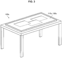
- FIG. 3 is an explanatory diagram illustrating an example of the configuration of an information processing device 100 c according to an embodiment of the present disclosure.
- FIG. 3 illustrates a state in which a touch panel type display is placed on a table.
- an input unit 110 c and an output unit 130 c can be configured as a touch panel type display. That is, in the information processing device 100 c illustrated in FIG. 3 , an information display surface is the touch panel type display.
- a camera for detecting the position of a user may be provided above the touch panel type display, as with the information processing device 100 a illustrated in FIG. 1 .
- the information processing device 100 a in which the input unit 110 a and the output unit 130 a are disposed above the table 140 a , that is, the information processing device 100 a in which the input unit 110 a and the output unit 130 a are disposed apart from the information display surface, will be described as an example.
- the information processing device 100 a , the input unit 110 a , and the output unit 130 a are simply referred to as the information processing device 100 , the input unit 110 , and the output unit 130 as well.
- FIG. 4 is an explanatory diagram for describing the overview of the information processing device 100 according to the present embodiment and illustrates an example in which a plurality of users simultaneously perform manipulations on the information processing device 100 .
- the information processing device 100 according to the present embodiment implements an environment in which a relatively large manipulation screen is projected onto a top surface of a table so that a plurality of users can simultaneously perform a manipulation, for example, as illustrated in FIG. 4 .
- reference numeral R 10 schematically indicates a region in which the information processing device 100 displays information (that is, an information display surface).
- a projection plane onto which the manipulation screen is projected by the projector corresponds to the display surface R 10 .
- each of reference numerals v 11 to v 14 indicates an example of a display object (for example, a display component such as a window) displayed on the information display surface R 10 in accordance with an operation of each application when different applications are executed.
- a user u 11 inputs information to a manipulation screen of a video chat application A 11 indicated by reference numeral v 11 by voice.
- a user u 12 inputs information to an input screen of an application A 12 for a voice search indicated by reference numeral v 12 by voice.
- a user u 13 inputs information to a screen of a browser A 13 indicated by reference numeral v 13 by voice.
- a user u 14 does not manipulate the information processing device 100 .
- an application A 14 of a music player is operating. Note that, in the present description, the music player application A 14 may display the manipulation screen v 14 on the display surface R 10 but does not have to display the manipulation screen v 14 on the display surface R 10 .
- a plurality of targets for example, applications
- a plurality of users may operate simultaneously, and a plurality of users may input information to the targets.
- the information processing device 100 was made in light of the situation described above, and a mechanism capable of inputting input information (for example, a voice input) from each user to the target (for example, an application) manipulated by the user even in the situation in which the plurality of users simultaneously perform manipulations is provided.
- input information for example, a voice input
- target for example, an application
- FIG. 5 is an explanatory diagram for describing the overview of control performed by the information processing device 100 according to the present embodiment and a diagram for describing an example of a mechanism in which the information processing device 100 identifies and acquires the voices spoken by the respective users.
- the information processing device 100 includes a microphone array including a plurality of sound collecting units 113 (for example, microphones) as the input unit 110 for collecting the acoustic information such as the voice spoken by the user, and estimates the arrival direction of the acoustic information in accordance with the sound collection results of the acoustic information by the respective sound collecting units 113 .
- a microphone array including a plurality of sound collecting units 113 (for example, microphones) as the input unit 110 for collecting the acoustic information such as the voice spoken by the user, and estimates the arrival direction of the acoustic information in accordance with the sound collection results of the acoustic information by the respective sound collecting units 113 .
- reference numeral R 20 schematically indicates a region in which the input unit 110 including the plurality of sound collecting units 113 can collect the acoustic information (hereinafter also referred to as a “sound collection region”).
- reference numeral R 21 indicates each partial region in a case in which the sound collection region R 20 is divided into a plurality of partial regions in accordance with directions using the position of the input unit 110 as a base point.
- the acoustic information arriving from the direction in which a partial region R 21 a extends using the position of the input unit 110 as the base point is assumed to be collected by the sound collecting units 113 in the input unit 110 .
- the acoustic information collected by the sound collecting unit 113 a facing the direction in which the partial region R 21 a extends among the plurality of sound collecting units 113 may have the highest volume.
- the acoustic information arriving from the direction in which the partial region R 21 a extends may also be collected by the sound collecting units 113 b and 113 c adjacent to the sound collecting unit 113 a .
- the volume of the acoustic information collected by the sound collecting units 113 b and 113 c is usually lower than the volume of the acoustic information collected by the sound collecting unit 113 a . Further, in most cases, the acoustic information arriving from the direction in which the partial region R 21 a extends is hardly collected by the sound collecting unit 113 d positioned on an opposite side to the sound collecting unit 113 a.
- the information processing device 100 estimates the arrival direction of the acoustic information (that is, the partial region R 21 in which the sound source of the acoustic information is positioned) in accordance with the ratio of the volume of each piece of acoustic information collected by the plurality of sound collecting units 113 included in the input unit 110 (for example, the array microphone).
- the information processing device 100 identifies and acquires a piece of acoustic information arriving from each of a plurality of partial regions R 21 into which the sound collection region R 20 of the input unit 110 is divided.
- the information processing device 100 can identify and acquire the voice spoken by the user positioned in the partial region R 21 for each partial region R 21 .
- a resolution of the partial region R 21 (in other words, the arrival direction) in which the information processing device 100 can identify and acquire each piece of acoustic information depends on the number of sound collecting units 113 serving as the input unit 110 and an arrangement of each of the sound collecting units 113 .
- the above described configuration of the input unit 110 is merely an example, and the configuration of the input unit 110 is not limited to the above configuration as long as it is possible to identify and acquire a piece of acoustic information arriving from each of the divided partial regions R 21 into which the sound collection region R 20 of the input unit 110 is divided.
- a directional microphone may be applied as each of the sound collecting units 113 serving as the input unit 110 .
- the information processing device 100 may estimate the arrival direction of the acoustic information (that is, the partial region R 21 in which the sound source of the acoustic information is positioned), for example, in accordance with the sound collecting unit 113 that collects the acoustic information among the plurality of sound collecting units 113 .
- a method of dividing the sound collection region R 20 into the plurality of partial regions R 21 is not limited to the division method according to the direction using the position of the input unit 110 as the base point.
- FIGS. 6 and 7 are explanatory diagrams for describing an overview of control performed by the information processing device 100 according to the present embodiment and a mechanism in which the information processing device 100 specifies an input destination of the acquired acoustic information.
- the information processing device 100 associates applications with any of the partial regions R 21 in the sound collection region R 20 of the input unit 110 illustrated in FIG. 5 in accordance with a state or context of an application being operated.
- the display surface R 10 is assumed to substantially coincide with the sound collection region R 20 of the input unit 110 as illustrated in FIGS. 6 and 7 .
- the display surface R 10 and the sound collection region R 20 need not necessarily have the same size or position.
- the partial region R 21 in the region R 20 corresponds to an example of a “target region.”
- FIG. 6 schematically illustrates a state in which only the video chat application A 11 among the applications A 11 to A 14 is receiving or is able to receive a voice input from the user.
- the state in which the application is receiving the voice input from the user or the state in which the application is able to receive the voice input from the user is also referred to as an “active state.”
- a state in which the application does not receive the voice input from the user is also referred to as an “inactive state.”
- the information processing device 100 associates the application A 11 in the active state with the partial region R 21 a in the sound collection region R 20 among the applications A 11 to A 14 that are in operation.
- the information processing device 100 checks that the application A 11 transitions to the activate state in a case in which the application A 11 is activated, in a case in which the application A 11 starts the reception of the voice input, or in a case in which the voice input is acquired. Note that, the information processing device 100 can recognize a timing at which the application A 11 starts the reception of the voice input, for example, on the basis of a predetermined manipulation corresponding to the application A 11 (for example, a predetermined touch manipulation performed on the display object v 11 ).
- the information processing device 100 specifies the size or the position of the partial region R 21 in the sound collection region R 20 to be associated with the application A 11 on the basis of the state or the context of the application A 11 that has transitioned to the active state.
- the information processing device 100 associates the partial region R 21 a superimposed on the display object v 11 corresponding to the application A 11 in the sound collection region R 20 , with the application A 11 .
- the information processing device 100 preferably specifies the partial region R 21 to be associated with the application serving as the target on the basis of at least one or more pieces of information of a position, a direction, and a size of the display object of the application (for example, the manipulation screen or the like).
- the information processing device 100 estimates the position of the user on the basis of the information such as the position, the direction, the size, or the like of the display object under the assumption that the user performs a manipulation while facing the display object of the application serving as the target. Further, it will be appreciated that the position of the user estimated at this time corresponds to the position of the sound source of the voice input toward the target application.
- the information processing device 100 may specify the partial region R 21 to be associated with the application serving as the target in accordance with the type of application.
- the above example is merely an example, and the method is not particularly limited as long as the information processing device 100 is able to specify the partial region R 21 to be associated with the application serving as the target in accordance with information related to the application.
- the information processing device 100 may associate, for example, management software operating at an operating system (OS) level (for example, a sound agent) with a partial region R 21 z other than the partial region R 21 a in the sound collection region R 20 .
- OS operating system
- the sound agent is assumed to operate as the management software at the OS level.
- the information processing device 100 allocates (in other words, inputs) the acoustic information to the application A 11 associated with the partial region R 21 a . Further, in a case in which the acoustic information arriving from a partial region R 21 other than the partial region R 21 a , that is, the partial region R 21 z , is acquired, the information processing device 100 allocates the acoustic information to the sound agent.
- FIG. 7 schematically illustrates an example in which the applications A 12 and A 13 enter the active state from the state illustrated in FIG. 6 .
- the information processing device 100 specifies the sizes or the positions of the partial regions R 21 in the sound collection region R 20 which is to be associated with the application A 12 and A 13 on the basis of the states or the contexts of the application A 12 and A 13 that have transitioned to the active state.
- the information processing device 100 associates a partial region R 21 c superimposed on the display object v 12 corresponding to the application A 12 in the sound collection region R 20 , with the application A 12 .
- the information processing device 100 associates a partial region R 21 e superimposed on the display object v 13 corresponding to the application A 13 in the sound collection region R 20 , with the application A 12 .
- the information processing device 100 associates partial regions R 21 b , R 21 d , and R 21 f with which the application in the active state is not associated, with the sound agent operating at the OS level.
- the information processing device 100 allocates the acoustic information to the application A 13 associated with the partial region R 21 c .
- the information processing device 100 allocates the acoustic information to the application A 14 associated with the partial region R 21 e .
- the information processing device 100 allocates the acoustic information to the sound agent.
- the information processing device 100 estimates the partial region R 21 in which the sound source of the acoustic information is positioned (that is, the arrival direction of the acoustic information) in accordance with the sound collection result of the acoustic information acquired by each of a plurality of sound collecting units 113 included in the input unit 110 .
- the information processing device 100 identifies and acquires the acoustic information arriving from each partial region R 21 in the sound collection region R 20 for each partial region R 21 .
- the information processing device 100 associates the application manipulated by each user (for example, to which the voice input is performed) with the partial region R 21 in the sound collection region R 20 in accordance with the state or the context of the application. Then, the information processing device 100 allocates the acoustic information identified and acquired for each partial region R 21 to the application associated with the partial region R 21 .
- the information processing device 100 has been described in connection with a form in which the application is associated with the partial region R 21 depending on whether or not the application is in the active state, but the information processing device 100 is not necessarily limited to this form. In other words, as long as the application is associated with any partial region R 21 in accordance with the state or the context of the application, the operation of the information processing device 100 is not necessarily limited to the above form.
- the information processing device 100 can identify and acquire the voice input from each user and input each voice input acquired from each user to the application manipulated by the user even in the situation in which a plurality of users simultaneously perform manipulations.
- the overview of the control performed by the information processing device 100 according to the present embodiment has been described above with reference to FIGS. 4 to 7 . Note that, the information processing device 100 according to the present embodiment will be described below in further detail.
- FIG. 8 is a block diagram illustrating an example of a functional configuration of the information processing device 100 according to the present embodiment. Note that, this description will proceed with an example in which the information processing device 100 is configured as a projection type.
- the information processing device 100 includes an input unit 1 . 10 , a control unit 120 , and an output unit 130 .
- the input unit 110 includes, for example, an imaging unit 111 and a sound collecting unit 113 .
- the output unit 130 includes, for example, a video output unit 131 .
- the output unit 130 may further include a sound output unit 133 .
- the input unit 110 is a component for acquiring content of manipulations performed by the user using the information processing device 100 on the information processing device 100 or information indicating a shape, a pattern, or the like of an object placed on a surface to which the output unit 130 outputs information (for example, the display surface R 10 such as the top surface of the table 140 a illustrated in FIG. 1 ).
- the content of manipulations performed by the user using the information processing device 100 on the information processing device 100 includes content of manipulations performed on a GUI which the information processing device 100 outputs to the information display surface.
- the imaging unit 111 included in the input unit 110 acquires the content of manipulations performed by the user on the information processing device 100 or the information indicating a shape, a pattern, or the like of an object placed on the display surface R 10 , as image information. Specifically, the imaging unit 111 captures, for example, an image of the display surface R 10 and outputs the captured image to a control unit 120 to be described later. Note that, the imaging unit 111 may be, for example, a camera including one imaging optical system, a stereo camera including two imaging optical systems, or the like.
- the sound collecting unit 113 included in the input unit 110 is a component for collecting the acoustic information such as the voice spoken by the user using the information processing device 100 and an ambient sound of an environment in which the information processing device 100 is placed.
- the information processing device 100 identifies and acquires the acoustic information arriving from each of a plurality of partial regions R 21 of the sound collection region R 20 (in other words, the acoustic information arriving in a plurality of directions). Therefore, for example, the input unit 110 may include a plurality of sound collecting units 113 , and a plurality of sound collecting units 113 may be configured as the array microphone. Note that, the following description will proceed with an example in which the input unit 110 includes a plurality of sound collecting units 113 , and a plurality of sound collecting units 113 are configured as the array microphone.
- Each of a plurality of sound collecting units 113 constituting the array microphone outputs the collected acoustic information to the control unit 120 to be described later.
- the control unit 120 controls the respective components of the information processing device 100 .
- the control unit 120 generates information to be output from the output unit 130 by using information input by the input unit 110 .
- the control unit 120 includes an input analyzing unit 121 , an allocation control unit 125 , a process executing unit 126 , and an output control unit 127 .
- the input analyzing unit 121 is a component for acquiring input information from the input unit 110 and analyzing the input information so that the process executing unit 126 or the output control unit 127 to be described later is operated. As illustrated in FIG. 8 , the input analyzing unit 121 includes, for example, a detecting unit 122 , an input source determining unit 123 , and an input destination specifying unit 124 .
- the detecting unit 122 executes a process of detecting the content of manipulations performed by the user using the information processing device 100 on the information processing device 100 , content of information output by the output unit 130 , and a shape, a pattern, or the like of an object placed on the display surface R 10 (for example, the table 140 a illustrated in FIG. 1 ) to which the output unit 130 outputs information.
- the detecting unit 122 acquires the image of the display surface R 10 captured by the imaging unit 111 , analyzes the image, and detects the above-described manipulator, the object placed on the display surface R 10 , or the like. At this time, when coordinates of the display surface R 10 for displaying information are calibrated to coincide with contact coordinates of the manipulator such as the hand of the user on the display surface R 10 in advance, for example, the detecting unit 122 can detect a portion of the GUI touched by the manipulator.
- the detecting unit 122 outputs the detected content, for example, to the output control unit 127 .
- the input source determining unit 123 is a component for determining the input source of the input information acquired by the input unit 110 .
- the input source determining unit 123 acquires the respective sound collection results of the acoustic information acquired by the plurality of sound collecting units 113 and estimates the partial region R 21 in the sound collection region R 20 in which the sound source of the acoustic information is positioned (in other words, the arrival direction of the acoustic information) in accordance with the acquired sound collection results. Note that, detailed description of the estimation method has been described above, and thus it is omitted in the present description.
- the input source determining unit 123 outputs the sound collection results of the acoustic information collected by the plurality of sound collecting units 113 and the estimation result of the partial region R 21 in which the sound source of the acoustic information is positioned, to the input destination specifying unit 124 .
- the input destination specifying unit 124 acquires the sound collection results of acoustic information collected by the plurality of sound collecting units 113 (for example, the voice spoken by the user) and the estimation result of the partial region R 21 in which the sound source of the acoustic information is positioned, from the input source determining unit 123 . Further, the input destination specifying unit 124 acquires information indicating each application that is in operation and the partial region R 21 associated with the application from the allocation control unit 125 to be described later.
- the input destination specifying unit 124 compares the estimation result of the partial region R 21 in which the sound source of acoustic information is positioned with the information indicating the partial region R 21 in which each application that is in operation is associated, and specifies an application associated with the partial region R 21 in which the sound source of the acoustic information is positioned. Note that, at this time, in a case in which there are a plurality of applications serving as candidates, the input destination specifying unit 124 may specify the application serving as the target on the basis of priorities of respective applications which are set in advance. Note that, an operation performed in a case in which there are a plurality of applications serving as candidates will be separately described later in detail as a modified example.
- the input destination specifying unit 124 outputs the acquired sound collection result of the acoustic information to the process executing unit 126 , and notifies the process executing unit 126 of the information indicating the specified application as the input destination of the acoustic information.
- the process executing unit 126 can recognize the application serving as the input destination of the acquired acoustic information even in the situation in which a plurality of applications are operated at the same time.
- the process executing unit 126 is a component for executing various kinds of processes of applications or the like.
- the process executing unit 126 extracts a corresponding application from a predetermined storage unit (not illustrated), for example, on the basis of an instruction given from the user via the input unit 110 , and executes the extracted application. Further, the process executing unit 126 may acquire input information from the input analyzing unit 121 and input the acquired input information to the application designated by the input analyzing unit 121 . Further, the process executing unit 126 outputs execution results of various kinds of executed applications to the output control unit 127 . Further, the process executing unit 126 may notify the allocation control unit 125 to be described later of information of various kinds of applications that are in execution (for example, types of applications or the like).
- the output control unit 127 generates output information to be output from the output unit 130 on the basis of an analysis result for the input information acquired by the input analyzing unit 121 , and causes the output unit 130 to output the output information.
- the output control unit 127 acquires control information indicating the detected manipulation content of the user from the input analyzing unit 121 . On the basis of the acquired control information, the output control unit 127 recognizes a manipulation target (for example, display object) designated on the basis of the user input and processing content on the manipulation target. Then, the output control unit 127 specifies the display object serving as a display control target in accordance with the specified manipulation target and the processing content, decides to display or not to display the specified display object, and controls a display position or direction and a display form (for example, a color or a size).
- a manipulation target for example, display object designated on the basis of the user input and processing content on the manipulation target.
- the output control unit 127 specifies the display object serving as a display control target in accordance with the specified manipulation target and the processing content, decides to display or not to display the specified display object, and controls a display position or direction and a display form (for example, a color or a size).
- the output control unit 127 may acquire the execution result of the application from the process executing unit 126 and perform generation of the output information or control related to an output of the output information on the basis of the execution result.
- the output control unit 127 may acquire an execution result of an application from the process executing unit 126 and present a display result to a display object (for example, a window) associated with the application.
- a display object for example, a window
- the output information that the output control unit 127 causes the output unit 130 to output is not limited to the display information such as the display object.
- the output control unit 127 may cause the output unit 130 to output the acoustic information (for example, a sound) as the output information.
- the output control unit 127 may manage various kinds of states of the application on the basis of a result of display control of each display object or execution results of various kinds of applications (or content).
- examples of the states of the application include an active state and an inactive state.
- Examples of information for recognizing whether or not the application is in the active state include information indicating whether or not a corresponding display object is selected, information indicating whether or not an application (or content) in execution, and information indicating whether or not an application (or a corresponding display object) is receiving an input.
- the output control unit 127 notifies the allocation control unit 125 of states of various kinds of applications and a control result of the output information corresponding to the application (for example, the display object).
- the allocation control unit 125 is a component for controlling an association between the partial regions included in the region (for example, the sound collection region R 20 illustrated in FIG. 5 ) in which the input unit 110 acquires the input information and various kinds of applications.
- the allocation control unit 125 acquires the information indicating the state or the context of various kinds of applications that are in operation from the process executing unit 126 or the output control unit 127 , and specifies the size or the position of the partial region to be associated with the application in accordance with the acquisition result.
- the allocation control unit 125 may specify the partial region R 21 associated with the application on the basis of the information such as the position, the direction, the size, or the like of the display object corresponding to the application that is in operation.
- the allocation control unit 125 may acquire information of the display object corresponding to various kinds of applications from the output control unit 127 and specify the partial region R 21 to be associated with the application in accordance with the acquired information.
- the allocation control unit 125 may recognize a relation between the sound collection region R 20 in which each sound collection unit 113 can collect the acoustic information and the display surface R 10 on which the output unit 130 displays the display information such as the display object, on the basis of a position relation between the respective sound collecting units 113 and the output unit 130 (particularly, the video output unit 131 to be described later), for example.
- the allocation control unit 125 may specify the partial region R 21 to be associated with the application in accordance with types of various kinds of applications.
- the allocation control unit 125 may acquire information indicating types of various kinds of applications from the process executing unit 126 and specify the partial region R 21 to be associated with the application in accordance with the acquired information.
- the allocation control unit 125 may specify the application to be associated with the partial region R 21 in accordance with the state of each application that is in operation. As a specific example, the allocation control unit 125 may associate the application transitioning to the active state among the applications that are in operation, with any of the partial regions R 21 . In this case, the allocation control unit 125 may determine whether or not each application is in the active state (or whether or not each application has transitioned to the active state) on the basis of the information acquired from the process executing unit 126 or the output control unit 127 .
- the allocation control unit 125 may associate the management software operating at the OS level such as the sound agent or the like with the partial region R 21 other than the partial region R 21 associated with the application among the partial regions R 21 .
- the allocation control unit 125 may perform control such that the association between the application and the partial region R 21 is canceled in accordance with the context or the state of the application associated with the partial region R 21 .
- the allocation control unit 125 may cancel the association between the application and the partial region R 21 in a case in which the application associated with the partial region R 21 transitions from the active state to the inactive state.
- the allocation control unit 125 is allowed to cancel the association between the application and the partial region R 21 in a case in which the application associated with the partial region R 21 ends.
- the allocation control unit 125 may associate the management software operating at the OS level with the partial region R 21 .
- a timing at which the allocation control unit 125 executes the above-described process is not particularly limited.
- the allocation control unit 125 may periodically monitor the state or the context of various kinds of applications and execute control related to the association between the application and the partial region R 21 in accordance with a monitoring result.
- the allocation control unit 125 may execute control related to the association between the application and the partial region R 21 by using a specific process as a trigger.
- the allocation control unit 125 may execute the control related to the association between the application and the partial region R 21 by using the transition of the state as a trigger.
- the output unit 130 outputs information in accordance with the manipulation content of the user using the information processing device 100 , content of the information output by the output unit 130 , and information such as the shape, the pattern or the like of the object placed on the display surface R 10 to which the output unit 130 outputs information (for example, the table 140 a illustrated in FIG. 1 ), which are input via the input unit 110 .
- the output unit 130 outputs information on the basis of information generated by the output control unit 127 .
- the video output unit 131 included in the output unit 130 is a component for outputting display information such as a screen (GUI) on which the display object is presented.
- GUI screen
- the video output unit 131 may be, for example, a projector for projecting the display information onto a desired projection plane (that is, display surface R 10 ).
- the sound output unit 133 included in the output unit 130 is a component for outputting the acoustic information such as a sound effect, music, or a voice as the output information.
- the sound output unit 133 may be, for example, an acoustic device such as a speaker.
- FIGS. 9 and 10 are flowcharts illustrating an example of a flow of a series of processes of the information processing device 100 according to the present embodiment.
- the allocation control unit 125 of the information processing device 100 acquires the information indicating the state or the context of various kinds of applications that are in operation from the process executing unit 126 or the output control unit 127 , and detects the application that has transitioned to the active state on the basis of the acquisition result.
- the allocation control unit 125 specifies the partial region R 21 to be associated with the application on the basis of the acquired information of the application.
- the allocation control unit 125 estimates the position of the user who manipulates the application on the basis of the position, the direction, the size, or the like of the display object corresponding to the application that has transitioned to the active state and specifies the partial region R 21 in which the user is positioned.
- the allocation control unit 125 associates the application that has transitioned to the active state with the specified partial region R 21 .
- the allocation control unit 125 may notify the input destination specifying unit 124 in the input analyzing unit 121 , of the information indicating the associations between various kinds of applications and the partial regions R 21 .
- the input destination specifying unit 124 can recognize the application associated with each partial region R 21 .
- step S 101 the allocation control unit 125 does not execute a process illustrated as step S 103 but proceeds to a next process.
- the allocation control unit 125 detects an application that has transitioned to the inactive state among the applications associated with the partial regions R 21 . Note that, in a case in which the application that has transitioned to the inactive state is not detected (NO in step S 105 ), the allocation control unit 125 does not execute the process related to steps S 107 to S 111 to be described later and proceeds to a next process.
- the allocation control unit 125 cancels the association between the detected application and the partial region R 21 associated with the application.
- the allocation control unit 125 checks whether or not another application is associated with the partial region R 21 .
- the allocation control unit 125 may associate the management software operating at the OS level with the partial region R 21 .
- the management software operating at the OS level for example, the sound agent may be used.
- step S 109 the allocation control unit 125 does not execute the process illustrated as step S 111 but proceeds to a next process.
- the information processing device 100 controls the association between the application and the partial region R 21 in accordance with the state or the context of various kinds of applications.
- a timing at which the information processing device 100 executes the above-described series of processes is not particularly limited.
- the information processing device 100 may periodically monitor the state or the context of various kinds of applications and execute control related to the association between the application and the partial region R 21 in accordance with a monitoring result.
- the information processing device 100 may execute control related to the association between the application and the partial region R 21 by using a specific process as a trigger.
- the information processing device 100 may execute the control related to the association between the application and the partial region R 21 by using the transition of the state as a trigger.
- steps S 101 to S 111 has been described as the flow of a series of processes.
- the process (steps S 101 to S 103 ) in the case of detecting the application that has transitioned to the active state and the process (step S 105 to S 111 ) in the case of detecting the application that has transitioned to the inactive state are performed separately at different timings.
- the input analyzing unit 121 of the information processing device 100 acquires the sound collection results of the acoustic information such as the voices spoken by the users or the ambient sound of the environment in which the information processing device 100 is placed from each of a plurality of sound collecting units 113 included in the array microphone.
- the input source determining unit 123 of the input analyzing unit 121 estimates the partial region R 21 in the sound collection region R 20 in which the sound source of the acoustic information is positioned in accordance with the acquired sound collection result ((in other words, the arrival direction of the acoustic information).
- the input analyzing unit 121 estimates the partial region R 21 in the sound collection region R 20 in which the sound source of the acoustic information is positioned in accordance with the ratio of the volumes of the acoustic information collected by a plurality of sound collecting units 113 included in the array microphone.
- the input source determining unit 123 outputs the sound collection results of the acoustic information collected by the plurality of sound collecting units 113 and the estimation result of the partial region R 21 in which the sound source of the acoustic information is positioned, to the input destination specifying unit 124 .
- the input destination specifying unit 124 acquires the sound collection results of acoustic information collected by the plurality of sound collecting units 113 (for example, the voice spoken by the user) and the estimation result of the partial region R 21 in which the sound source of the acoustic information is positioned, from the input source determining unit 123 . Further, the input destination specifying unit 124 acquires information indicating each application that is in operation and the partial region R 21 associated with the application from the allocation control unit 125 .
- the input destination specifying unit 124 compares the estimation result of the partial region R 21 in which the sound source of acoustic information is positioned with the information indicating the partial region R 21 in which each application that is in operation is associated, and specifies an application associated with the partial region R 21 in which the sound source of the acoustic information is positioned. In other words, the input destination specifying unit 124 specifies the application associated with the partial region R 21 in which the sound source of the acoustic information is positioned as the input destination of the acquired acoustic information.
- the input destination specifying unit 124 outputs the acquired sound collection result of the acoustic information to the process executing unit 126 , and notifies the process executing unit 126 of the information indicating the specified application as the input destination of the acoustic information.
- the process executing unit 126 can recognize the application serving as the input destination of the acquired acoustic information even in the situation in which a plurality of applications are operated at the same time.
- FIGS. 11 to 13 are explanatory diagrams for describing an example of control of the information processing device 100 according to the first modified example.
- the information processing device 100 inputs the acquired acoustic information only to one of a plurality of candidate applications (hereinafter also referred to as “exclusive control”) will be described.
- exclusive control an example of control in which the information processing device 100 inputs the acquired acoustic information only to one of a plurality of candidate applications.
- the present description will proceed with an example in which the information processing device 100 associates the application with the partial region on the basis of the information such as the position, the direction, or the size of the display object of the application serving as the target.
- FIG. 11 illustrates an example in which a voice search application A 41 and a web browser A 42 (also referred to simply as an “application A 42 ”) are associated with a common partial region.
- reference numeral v 41 indicates a display object (for example, a manipulation screen) corresponding to the application A 41 .
- reference numeral v 42 indicates a display object corresponding to the web browser A 42 .
- the partial region in the sound collection region R 20 is set in accordance with a direction based on a predetermined reference position (for example, the position of the input unit 110 ).
- a predetermined reference position for example, the position of the input unit 110 .
- the application A 41 and the application A 42 are associated with a partial region formed between a 210° direction and a 240° direction in a case in which a predetermined direction based on the reference position (for example, an upper direction in FIG. 11 ) is 0°.
- the partial region formed between the 210° direction and the 240° direction is also referred to as a “partial region 210 - 240 .”
- a right diagram of FIG. 11 illustrates an example of a relation of each application (program), a partial region associated with the application, a priority of each application, and a mode set in each application.
- the mode set in each application indicates whether or not the exclusive control is performed on the input of the acoustic information, and in the example illustrated in FIG. 11 , the “Exclusive (exclusive control)” is set in both the applications A 41 and A 42 .
- the information processing device 100 does not perform the exclusive control among a plurality of applications when the acoustic information is input will be separately described later as a second modified example.
- the information processing device 100 sets priorities such that a high priority is assigned to an application of which a corresponding display object is displayed in a higher layer among a plurality of applications associated with the common partial region.
- the display object v 41 is displayed in a layer (for example, a forefront layer) higher than the display object v 42 . Therefore, the information processing device 100 sets the priority of the voice search application A 41 to be higher than the priority of the web browser A 42 .
- the Exclusive (exclusive control) is set as mode in both the application A 41 and A 42 . Therefore, in the example illustrated in FIG. 11 , the information processing device 100 inputs the acoustic information acquired from the partial region 210 - 240 to the voice search application A 41 with a higher priority among the applications A 41 and A 42 associated with the partial region 210 - 240 .
- FIG. 12 illustrates an example in which the display object v 42 corresponding to the web browser A 42 is selected by the user in the state illustrated in FIG. 11 , and the display object v 42 is displayed on the forefront.
- the information processing device 100 updates the priorities set in the applications so that the priority of the web browser A 42 whose display object is displayed on the higher layer becomes higher than the priority of the application A 41 .
- the information processing device 100 inputs the acoustic information acquired from the partial region 210 - 240 to the web browser A 42 having a higher priority among the applications A 41 and A 42 associated with the partial region 210 - 240 .
- FIG. 13 illustrates an example in which a plurality of applications are associated with different partial regions, and the partial regions partially overlap.
- the web browser A 42 is associated with a partial region 210 - 240 formed between a 210° direction and a 240° direction in a case in which a predetermined direction based on a reference position (for example, an upper direction in FIG. 13 ) is 0°.
- the application A 43 that presents a map is associated with a partial region 135 - 225 formed between a 135° direction and a 225° direction in a case in which the predetermined direction is 0°.
- the partial regions 210 - 240 and the partial regions 135 - 225 overlaps in a region 210 - 225 formed between the 210° direction and the 225° direction.
- reference numeral A 42 indicates a display object corresponding to the web browser A 42 .
- reference numeral A 43 indicates a display object corresponding to the application A 43 presenting the map.
- the information processing device 100 is assumed to set priorities of the applications such that a high priority is assigned to an application in which a corresponding display object is displayed in a higher layer.
- the display object v 42 is displayed in a layer (for example, a forefront layer) higher than the display object v 43 . Therefore, the information processing device 100 sets the priority of the web browser A 42 to be higher than the priority of the application A 43 presenting the map.
- Exclusive exclusive control
- the information processing device 100 is assumed to acquire the acoustic information from a region 225 - 240 not overlapping the partial region 135 - 225 in the partial region 210 - 240 associated with the web browser A 42 .
- the web browser A 42 is associated with the region 225 - 240 included in the partial region 210 - 240 . Therefore, the information processing device 100 inputs the acoustic information acquired from the region 225 - 240 into the web browser A 42 .
- the information processing device 100 is assumed to acquire the acoustic information from a region 135 - 210 not overlapping with the partial region 210 - 240 in the partial region 135 - 225 associated with the application A 43 presenting the map.
- the application 443 presenting the map is associated with the region 135 - 210 included in the partial region 135 - 225 . Therefore, the information processing device 100 inputs the acoustic information acquired from the region 135 - 210 to the application A 43 presenting the map.
- the web browser A 42 and the application A 43 presenting the map are associated with the region 210 - 225 in which the partial regions 135 - 225 and the partial regions 210 - 240 overlap.
- the Exclusive (exclusive control) is set in both the application A 42 and A 43 as a mode. Therefore, in a case in which the acoustic information is acquired from the region 210 - 225 , the information processing device 100 decides the input destination of the acoustic information on the basis of the priorities set in the applications A 42 and A 43 .
- the priority of the web browser A 42 is set to be higher than the priority of the application A 43 presenting the map. Therefore, in a case in which the acoustic information is acquired from the region 210 - 225 , the information processing device 100 inputs the acoustic information to the web browser A 42 on which the higher priority is set.
- the example of the control of the information processing device 100 performed in the case in which there are a plurality of applications serving as the candidates for the input destination of the acoustic information acquired as the input information has been described with reference to FIGS. 11 to 13 as the first modified example.
- the information processing device 100 is able to set the priorities of the applications even in the situation in which there are a plurality of applications serving as the candidates for the input destination of the acoustic information and able to decide the input destination of the acquired acoustic information on the basis of the priority.
- the information processing device 100 sets the priorities of the applications associated with the common partial region in accordance with the position relation between the layers in which the corresponding display object is displayed.
- the above example is merely an example, and as long as the information processing device 100 can set the priorities of the applications associated with the common partial region, the method is not particularly limited.
- the information processing device 100 may assign the priority such that a higher priority is assigned to an application of which a corresponding display object is positioned on the outer side of the display surface R 10 among the applications associated with the common partial region.
- the information processing device 100 may set the priority of an application associated with the common partial region on the basis of the size of the partial region associated with each application. As a specific example, the information processing device 100 may assign the priority such that a priority of an application associated with a narrower partial region becomes higher than a priority of an application associated with a wider partial region.
- Second Modified Example Second Control Example in a Case in which there are a Plurality of Input Destination Candidates
- FIGS. 14 and 15 are explanatory diagrams for describing an example of the control of the information processing device 100 according to the second modified example.
- the example of the control of the information processing device 100 performed in the cases in which the acoustic information is input only to one of the applications (that is, the exclusive control is performed) in the situation in which there are a plurality of applications serving as the candidates for the input destination of the acoustic information acquired as the input information has been described.
- an example of control of the information processing device 100 performed in a case in which the acoustic information is input to each of the applications in a situation in which there are a plurality of applications serving as the candidates for the input destination will be described.
- FIG. 14 illustrates an example in which a web browser A 42 is associated with a partial region 210 - 240 , a conference call application A 44 is associated with a partial region 0 - 360 (that is, the entire sound collection region R 20 ).
- the Exclusive exclusive control
- the priority of the web browser A 42 is assumed to be set to be higher than the priority of the conference call application A 44 .
- the information processing device 100 inputs the acoustic information acquired from the partial region 240 - 210 to the conference call application A 44 .
- the applications A 42 and A 44 are associated with the partial regions 210 to 240 formed from the 210° direction to the 240° direction clockwise, and the Exclusive (exclusive control) is set in both the applications A 42 and A 44 as a mode. Therefore, as described above in the first modified example, the information processing device 100 performs the exclusive control on the input of the acoustic information between the application A 42 and A 44 . In other words, in the example illustrated in FIG. 14 , the information processing device 100 inputs the acoustic information acquired from the partial region 210 - 240 only to the web browser A 42 in which the higher priority is set.
- the information processing device 100 may perform control such that the acoustic information acquired from the partial region 210 - 240 is input to the conference call application A 44 in addition to the web browser A 42 on the basis of an instruction given from the user.
- FIG. 15 illustrates an example of control performed in a case in which the information processing device 100 inputs the acoustic information acquired from the partial region 210 - 240 to the conference call application A 44 in addition to the web browser A 42 .
- the information processing device 100 receives a manipulation performed by the user on the partial region 210 - 240 , and changes the mode of the application associated with the partial region 210 - 240 from “Exclusive” to “Through” in which the input information is shared by the applications. For example, in the example illustrated in FIG. 15 , the information processing device 100 changes the mode of the web browser A 42 to “Through.”
- the information processing device 100 may present a display object v 421 indicating a reception state of the input information (sound) to the web browser A 42 (for example, a fan-like display object of presenting the partial region 210 - 240 ) to the user, receive a predetermined user manipulation related to a mode change (for example, a touch manipulation) performed on the display object v 421 , and change the mode of the web browser A 42 .
- a mode change for example, a touch manipulation
- the information processing device 100 may present a display object v 441 indicating a reception state of the input information (sound) to the application A 44 to the user, receive the user manipulation (for example, the touch manipulation) performed on the display object v 441 , and change the mode of the application A 44 .
- the information processing device 100 may receive a predetermined manipulation related to the mode change performed on the display object corresponding to each application from the user and change the mode of the application corresponding to the display object.
- the information processing device 100 may control the mode setting in units of partial regions.
- the information processing device 100 may be able to change the mode in only some regions (for example, the region 210 - 220 ) in the partial region 210 - 240 with associated the web browser A 42 , in this case, the information processing device 100 may be able to receive designation of the partial region issued by the user and a predetermined manipulation related to the mode change performed on the partial region and change the mode set in the partial region.
- the information processing device 100 inputs the input information (for example, the acoustic information) to be input to the application to which “Through” is set to other applications with the lower priority than the application.
- the information processing device 100 inputs the acoustic information acquired from the partial region 210 - 240 to the web browser A 42 on which a higher priority is set. Further, since “Through” is set as the mode of the web browser A 42 , the information processing device 100 also inputs the acoustic information to the conference call application A 44 having the lower priority than the web browser A 42 .
- the example of the control of the information processing device 100 in which the acoustic information is input to each application in the situation in which there are a plurality of applications serving as the candidates for the input destination has been described as the second modified example with reference to FIGS. 14 and 15 .
- the information processing device 100 can input the acoustic information to each application on the basis of the control of the mode set in each application serving as the candidate for the input destination.
- the user can appropriately cancel the exclusive control between the applications associated with a desired partial region and input input information (for example, the acoustic information such as the voice) to each application.
- the information processing device 100 may cause a display object for visualizing each partial region associated with the application to be presented on the display surface R 10 .
- the information processing device 100 causes each partial region associated with the application to be presented on the display surface R 10 as the fan-like display object (for example, the display objects v 421 and v 441 ).
- FIG. 16 is an explanatory diagram for describing an overview of the information processing device 100 according to a third modified example and illustrates an example of a display form of a display object for visualizing each partial region.
- applications A 11 , A 12 , and A 13 are associated with partial regions R 21 a , R 21 c , and R 21 e among partial regions R 21 a to R 21 f in the sound collection region R 20 .
- the management software for example, sound agent operating at the OS level is associated with the partial regions R 21 b , R 21 d , and R 21 f.
- reference numeral v 31 is a display object indicating the partial region R 21 a .
- reference numeral v 31 is a display object indicating the partial region R 21 c .
- reference numeral v 33 is a display object indicating the partial region R 21 e.
- the information processing device 100 causes the display objects v 31 to v 33 indicating the respective partial regions to be displayed in portions which the partial regions R 21 a , R 21 c , and R 21 e overlap in an outer edge portion of the display surface R 10 .
- the information processing device 100 causes the display object indicating the partial region to be displayed on the display surface R 10 with respect to the partial region associated with an application other than the management software operating at the OS level (for example, an application in the active state) among the partial regions.
- the information processing device 100 may present the user with the display object indicating the partial region with respect to a partial region satisfying a specific condition (for example, a partial region associated with an application in the active state) only.
- the information processing device 100 may present the user with information so that a relation between each partial region and the application associated with the partial region can be identified. Specifically, with respect to a certain partial region, the information processing device 100 may display identification information common to the display object indicating the partial region and the display object corresponding to the application associated with the partial region.
- the information processing device 100 may assign, to a display object corresponding to an application associated with a partial region, a marker of the same color as the display object indicating the partial region as the identification information. Accordingly, the user can easily recognize that the partial region and the display object (that is, the application) that are presented in the same color are associated with each other.
- the example in which the information processing device 100 presents each partial region associated with the application as the display information has been described above.
- the above example is merely an example, and the method is not particularly limited as long as the information processing device 100 can present each partial region associated with the application to the user.
- the information processing device 100 may present each partial region to the user by causing a light emitting unit such as an LED (light-emitting diodes) to emit light.
- FIG. 17 is an explanatory diagram for describing an overview of the information processing device 100 according to the fourth modified example and illustrates an example in which the information processing device 100 controls the output amount of the acoustic information output from each application, for each partial region.
- the information processing device 100 can control the output of the acoustic information for each partial region.
- a plurality of directional speakers are disposed for the information processing, device 100 , and each directional speaker is associated with one of the partial regions R 21 in the sound collection region R 20 . Then, the position or the direction of each directional speaker is adjusted in advance so that an output destination of the acoustic information of each directional speaker (that is, a direction in which the acoustic information is output) becomes the partial region associated with the directional speaker.
- the information processing device 100 can individually control the output of the acoustic information for each partial region individually by controlling the output of the acoustic information for each directional speaker.
- applications A 11 , A 12 , and A 13 which is receiving a manipulation from specific users (that is, in the active state) are associated with partial regions R 21 a , R 21 c , and R 21 e among partial regions R 21 a to R 21 f in the sound collection region R 20 .
- the management software for example, sound agent
- the music player application indicated by reference numeral A 14 is in a state in which the manipulation of the specific user is not received (that is, the inactive state) and operates on the basis of management of the management software operating at the OS level.
- the information processing device 100 sets the output amount of the acoustic information output from the application A 14 in the inactive state to 100% for the partial regions R 21 b , R 21 d , and R 21 f associated with the management software operating at the OS level. Further, the information processing device 100 does not output (or suppresses the output of) the acoustic information output from the other applications A 11 to A 13 for the partial regions R 21 b , R 21 d , and R 21 f . In other words, the users positioned in the partial regions R 21 b , R 21 d , and R 21 f only recognizes the acoustic information output from the music player application A 14 .
- the information processing device 100 sets the output amount of the acoustic information output from the application A 11 to 100% for the partial region R 21 a . Further, the information processing device 100 suppress the output of the acoustic information so that the output amount of the acoustic information output from the application A 14 operating on the basis of the management of the management software (that is, in the inactive state) is 20% for the partial region R 21 a . In other words, the user positioned in the partial region R 21 a recognizes the acoustic information output from the application A 11 and the application A 14 . In addition, at this time, the volume of the acoustic information output from the application A 11 is larger than the volume of the acoustic information output from the application A 14 .
- the information processing device 100 sets the output amount of the acoustic information output from the application A 12 to 100% for partial region R 21 c . Further, the information processing device 100 suppress the output of the acoustic information so that acoustic information is not output from the application A 14 operating on the basis of the management of the management software (that is, the output becomes 0%) for the partial region R 21 c . In other words, the user positioned in the partial region R 21 a only recognizes the acoustic information output from the application A 12 .
- the information processing device 100 suppresses the output so that the output amount of the acoustic information output from the application A 13 is 50% for the partial region R 21 e . Further, the information processing device 100 sets the output amount of the acoustic information output from the application A 14 operating on the basis of the management of the management software to 100% for the partial region R 21 e . In other words, the user positioned in partial region R 21 e recognizes the acoustic information output from the applications A 13 and A 14 . In addition, at this time, the volume of the acoustic information output from the application A 13 is smaller than the volume of the acoustic information output from the application A 14 .
- the information processing device 100 may control the output amount (that is, the output ratio) of the output information from each application for each partial region.
- the information processing device 100 may be configured so that the output amount of information output from each application for each partial region can be controlled on the basis of the user manipulation on the partial region.
- the information processing device 100 may receive a predetermined user manipulation performed on the partial region and present a user interface (UI) such as a mixing console for controlling the output ratio of the output information output from each application for the partial region.
- UI user interface
- the information processing device 100 may control the output amount of the output information from each application to the partial region on the basis of the output ratio set through the UI.
- the output amount of the acoustic information output from each application is controlled for each partial region, but information serving as a control target is not necessarily limited to the acoustic information as long as it is possible to control an output amount of information output from each application.
- the example in which the information processing device 100 controls the output amount (for example, the volume) of the output information output from each application for each partial region has been described above as the fourth modified example with reference to FIG. 17 .
- the information processing device 100 receives a user manipulation and controls a form of a partial region designated on the basis of the manipulation or an operation associated with the partial region will be described as a fifth modified example.
- the information processing device 100 may change the position or the size of the partial region associated with each application on the basis of an instruction (for example, a user manipulation) given from the user.
- an instruction for example, a user manipulation
- FIG. 18 is an explanatory diagram for describing an overview of the information processing device 100 according to the fifth modified example and illustrates an example in which the information processing device 100 receives a manipulation from the user and changes the position or the size of the partial region.
- the information processing device 100 presents the display object v 441 indicating a partial region associated with the conference call application A 44 , and changes the size of the partial region on the basis of the user manipulation performed on the display object v 441 .
- the information processing device 100 increases or decreases the size of the partial region associated with the application A 44 in accordance with the pinch manipulation.
- FIG. 19 is an explanatory diagram for describing an overview of the information processing device 100 according to the fifth modified example and illustrates an example in which the information processing device 100 receives a manipulation from the user and temporarily stops acquisition of input information from the partial region.
- the information processing device 100 presents the display object v 441 indicating the partial region associated with the conference call application A 44 .
- the information processing device 100 receives a predetermined manipulation (for example, a tap manipulation) performed on a region v 442 of a part of the display object v 441 from the user, the information processing device 100 temporarily stops the input of the acoustic information from the region v 442 to the application A 44 .
- a predetermined manipulation for example, a tap manipulation
- the user can perform a predetermined manipulation on at least a region of a part of the partial region in which a predetermined application can receive an input, and temporarily stop (that is, partially mute) the input of the acoustic information from the region of the part of the partial region to the application.
- the information processing device 100 may receive a manipulation for changing the position or the direction of the display object corresponding to the application and change the position or the size of the partial region associated with the application in accordance with the change in the position or the direction of the display object.
- FIG. 20 is an explanatory diagram for describing an overview of the information processing device 100 according to the fifth modified example.
- the information processing device 100 receives a manipulation for changing the position of the display object from the user and updates the position of the partial region associated with the application corresponding to the display object.
- FIG. 20 illustrates an example in which the user moves the position of the display object corresponding to the application A 12 from a position indicated by reference numeral v 12 to a position indicated by reference numeral v 12 ′, for example, by a drag manipulation.
- reference numeral R 241 indicates the partial region associated with the application A 12 on the basis of the position of the display object indicated by reference numeral v 12 .
- reference numeral R 242 indicates the partial region associated with the application A 12 on the basis of the position of the display object indicated by reference numeral v 12 ′.
- the information processing device 100 updates the position of the partial region associated with the application A 12 in response to the change.
- the information processing device 100 sequentially monitors a situation changing in accordance with the manipulation performed by the user or the like, and dynamically changes the association between various kinds of applications and the partial regions in response to the change.
- the example illustrated in FIG. 20 is merely an example, and the information processing device 100 does not have to change the association between various kinds of applications and the partial regions in a case in which the situation changes in accordance with the manipulation performed by the user (for example, in a case in which the position of the display object is changed).
- the information processing device 100 preferably associates the application with the partial region at a predetermined timing (for example, a timing at which the application is started, a timing at which the application transitions to the active state, or the like) and maintains the association even in a case in which the situation is changed.
- the example in which the information processing device 100 receives the user manipulation and controls the form of the partial region designated on the basis of the manipulation or the operation associated with the partial region has been described as the fifth modified example with reference to FIGS. 10 to 20 .
- each function described above may be configured to operate regularly or may be configured so that switching between enable and disable is performed on the basis of a predetermined user manipulation.
- FIG. 21 is an explanatory diagram for describing an example of control of the information processing device 100 according to the sixth modified example.
- the applications A 11 , A 12 , and A 13 are associated with the partial regions R 21 a , R 21 c , and R 21 e among the partial regions R 21 a to R 21 f in the sound collection region R 20 .
- the management software for example, sound agent
- the music player application A 14 is assumed to operate on the basis of the management of the management software operating at the OS level.
- the information processing device 100 recognizes a voice spoken by a user u 12 manipulating the application A 12 as the acoustic information arriving from the partial region R 21 c , and inputs the acoustic information to the application A 12 associated with the partial region R 21 c.
- the user u 12 can temporarily input information (for example, sound information) to another application (for example, the music player application A 14 ).
- the user u 12 can move to a partial region that is associated with a desired application and input information to the desired application, but an operation of inputting the information gets complicated in many cases.
- the information processing device 100 provides a function of temporarily changing an application serving as the input destination of the input information input from a desired partial region, on the basis of a predetermined manipulation performed by the user.
- the information processing device 100 detects a predetermined word (hereinafter also referred to as a “magic word”) in voices (that is, input voices) spoken by the user, the information processing device 100 recognizes a voice subsequent to the magic word as control information. Then, the information processing device 100 temporarily changes the input destination of the acoustic information (that is, the voice input) output from the partial region on the basis of content of the recognized control information.
- a predetermined word hereinafter also referred to as a “magic word”
- voice that is, input voices
- the information processing device 100 recognizes a voice subsequent to the magic word as control information. Then, the information processing device 100 temporarily changes the input destination of the acoustic information (that is, the voice input) output from the partial region on the basis of content of the recognized control information.
- the user u 12 positioned in the partial region R 21 c speaks “change music to next song” as the control information for manipulating the music player application A 14 after speaking the magic word.
- the information processing device 100 first detects the magic word as a result of a recognition process on the voice input from the user u 12 acquired from the partial region R 21 c . Then, with the detection of the magic word, the information processing device 100 performs semantic analysis on the control information subsequent to the magic word and recognizes that content thereof is a manipulation of the music player application A 14 . In other words, in this case, the information processing device 100 temporarily changes the input destination of the voice input acquired from the partial region R 21 c from the application A 12 associated with the partial region R 21 c to the music player application A 14 .
- the user u 12 need not perform a complicated manipulation such as position movement in order to input information to the music player application A 14 .
- the information processing device 100 may be configured to be able to input an instruction to the management software (for example, the sound agent) operating at the OS level, as the control information.
- the management software for example, the sound agent
- the user u 12 is assumed to speak “turn off system” as the control information for giving an instruction to the management software operating at the OS level, after speaking the magic word.
- the information processing device 100 detects the magic word as a result of the recognition processing performed on the voice input, performs the semantic analysis on the control information subsequent to the magic word, and recognizes that content thereof is an instruction given to the management software operating at the OS level. Then, the information processing device 100 inputs the acquired voice input “turn off system” to the management software operating at the OS level. In other words, in this case, the management software operating at the OS level receives the voice input and turns off the system.
- examples of the instruction given to the management software operating at the OS level include turning on/off of a computer (that is, start and end of a system), turning on/off of a connected illumination device, a setting of various kinds of systems, and activation/deactivation of an application.
- FIG. 22 is a flowchart illustrating an example of a flow of a series of processes of the information processing device 100 according to the sixth modified example.
- the information processing device 100 identifies and acquires the input voice (that is, the acoustic information) from each user for each partial region, and recognizes content of the acquired input voice as, for example, character information on the basis of a technique such as speech recognition. Then, the information processing device 100 can extract an expression such as words included in the input voice by, for example, performing syntax analysis on the content of the input voice recognized as the character information.
- the information processing device 100 When the information processing device 100 recognizes the content of the acquired input voice, the information processing device 100 checks whether or not the magic word is included in the recognized input voice.
- the information processing device 100 recognizes the voice subsequent to the magic word as the control information, performs the semantic analysis on the control information, and recognizes the content of the control information.
- the user is assumed to speak “turn off system” after speaking the magic word.
- the information processing device 100 recognizes the voice “turn off system” as the control information and recognizes that the control information is an instruction to turn off the system from a result of the semantic analysis performed on the recognized control information.
- the information processing device 100 When the semantic analysis is performed on the recognized control information, the information processing device 100 generates a command to execute control corresponding to the control information from the result of the semantic analysis (step S 307 ) and executes the generated command (step S 309 ).
- the information processing device 100 recognizes an instruction related to turning-off of a system with regard to the management software operating at the OS level, the information processing device 100 generates a command to cause the management software to execute the instruction related to the turning-off of the system on the basis of the instruction. Subsequently, when the command generated by the information processing device 100 is executed, the management software turns off the system in accordance with the execution of the command.
- entities of performing the semantic analysis on the control information, generating the command based on the result of the semantic analysis, and performing the process related to the execution of the generated command are not particularly limited. As a specific example, for example, some or all of these processes may be performed by the management software (for example, the sound agent) operating at the OS level.
- the information processing device 100 recognizes the control information by using the magic word, but a method thereof is not particularly limited as long as the information processing device 100 can recognize that the input information is the control information.
- a method thereof is not particularly limited as long as the information processing device 100 can recognize that the input information is the control information.
- the information processing device 100 may recognize that input information that has been input subsequently is the control information.
- the information processing device 100 estimates the partial region R 21 in which the sound source of the acoustic information is positioned (that is, the arrival direction of the acoustic information) in accordance with the sound collection result of the acoustic information acquired by each of a plurality of sound collecting units 113 included in the input unit 110 .
- the information processing device 100 identifies and acquires the acoustic information arriving from each partial region R 21 in the sound collection region R 20 for each partial region R 21 .
- the information processing device 100 associates the application manipulated by each user (for example, to which the voice input is performed) with the partial region R 21 in the sound collection region R 20 in accordance with the state or the context of the application. Then, the information processing device 100 allocates the acoustic information identified and acquired for each partial region R 21 to the application associated with the partial region R 21 .
- the information processing device 100 can identify and acquire the voice input from each user even in the situation in which a plurality of users simultaneously perform manipulations and input each acquired voice input to an application manipulated by each of the users.
- the display surface R 10 and the sound collection region R 20 have been described as substantially coinciding with each other in order to further facilitate understanding of features of the information processing device 100 .
- the display surface R 10 and the sound collection region R 20 need not necessarily be identical in the size or the position thereof.
- the configuration of the information processing device 100 is not limited to the example described above as long as various kinds of applications that are in operation are associated with the partial region R 21 in the sound collection region R 20 , and the input information acquired from the partial region R 21 is input to the application associated with the partial region R 21 .
- the information processing device 100 may not have a configuration for causing the display information to be displayed on the display surface R 10 .
- the information processing device 100 may be configured as an interactive sound agent that presents information to the user by voice in response to the voice input from the user.
- the information processing device 100 acquires the acoustic information such as a voice as the input information and controls the input destination of the acoustic information.
- the input information is not necessarily limited to the acoustic information.
- an example in which the information processing device 100 causes a video chat application to be operated will be described as an example in which the information processing device 100 acquires video information as input information other than the acoustic information and controls the input destination of the video information.
- FIG. 23 is an explanatory diagram for describing an overview of the information processing device 100 according to the present embodiment and illustrates an example of a schematic configuration of the information processing device 100 .
- FIG. 23 illustrates an example in which the information processing device 100 is configured as a projection type as illustrated in FIG. 1 .
- a configuration and processing content of the information processing device 100 according to the present embodiment will be described focusing on portions different from the information processing device 100 according to the first embodiment, and detailed descriptions of similar portions are omitted.
- reference numeral v 51 indicates a display object corresponding to a video chat application manipulated by a user u 11 .
- reference numeral v 52 indicates a display object corresponding to a video chat application manipulated by a user u 12 .
- the information processing device 100 includes an imaging unit 150 that captures a video of the user manipulating the video chat application.
- the imaging unit 111 included in the input unit 110 that is, the imaging unit for capturing the image of the display surface R 10
- the imaging unit 150 that captures the video of the user from each other, sometimes the imaging unit 111 is also referred to as a “first imaging unit 111 ,” and the imaging unit 150 is also referred to as a “second imaging unit 150 .”
- the second imaging unit 150 may be configured as a wide-angle camera (for example, an upward wide-angle camera) capable of capturing an image of a 360° range such as a so-called omnidirectional camera.
- the second imaging unit 150 is installed at a desired position on the display surface R 10 .
- the information processing device 100 acquires an image around the second imaging unit 150 (that is, the image around the display surface R 10 ) from the second imaging unit 150 installed on the display surface R 10 . Then, the information processing device 100 clips partial images of the users u 11 and u 12 performing manipulations on the display objects v 51 and v 52 from the acquired image and allocates each of the clipped partial images to applications corresponding to the display objects v 51 and v 52 . In this regard, such an operation of the information processing device 100 will be described in detail with reference to FIG. 24 .
- FIG. 24 is an explanatory diagram for describing an example of control performed by the information processing device 100 according to the present embodiment.
- reference numerals R 51 and R 52 indicate respective partial regions included in an imaging region in which the second imaging unit 150 is capable of capturing an image.
- the information processing device 100 associates the video chat applications manipulated by the respective users with the partial regions in the imaging region of the second imaging unit 150 . Then, the information processing device 100 clips an image (that is, a video input) corresponding to each partial region from the image acquired from the second imaging unit 150 and allocates the image clipped for each partial region to the application associated with the partial region.
- a marker 151 for specifying the position or the direction of the second imaging unit 150 is attached to the second imaging unit 150 .
- the information processing device 100 analyzes the image of the display surface R 10 captured through the first imaging unit 111 in the input unit 110 , and specifies the position and the direction of the second imaging unit 150 in the display surface R 10 on the basis of the second imaging unit 150 and the marker 151 captured in the image.
- the information processing device 100 specifies the partial region to be associated with the application on the basis of the position and the direction of the second imaging unit 150 and information indicating the state or the context of the application (for example, the video chat application) using the image captured by the second imaging unit 150 .
- the information processing device 100 specifies the partial region associated with the application on the basis of the position and the direction of the second imaging unit 150 and the position, the direction, and the size of the display object corresponding to each application.
- the information processing device 100 estimates a relative position of the user u 11 with respect to the second imaging unit 150 on the basis of the position and the direction of the second imaging unit 150 and the position, the direction, and the size of a display object v 51 under the assumption that the user u 11 faces the display object v 51 .
- the information processing device 100 specifies the partial region R 51 extending toward the position of the user u 11 estimated from the position of the second imaging unit 150 on the basis of the estimated relative position of the user u 11 with respect to the second imaging unit 150 .
- the information processing device 100 associates the video chat application corresponding to the display object v 51 (that is, the application of controlling the display of the display object v 51 ) with the specified partial region R 51 .
- the information processing device 100 estimates a relative position of the user u 12 with respect to the second imaging unit 150 on the basis of the position and the direction of the second imaging unit 150 and the position, the direction, and the size of the display object v 52 .
- the information processing device 100 specifies the partial region R 52 on the basis of the estimated relative position of the user u 11 with respect to the second imaging unit 150 and associates the video chat application corresponding to the display object v 52 with the specified partial region R 51 .
- the information processing device 100 acquires the image captured by the second imaging unit 150 and clips the partial image corresponding to the partial region associated with each application from the acquired image on the basis of the recognized position and the direction of the second imaging unit 150 .
- the information processing device 100 specifies a direction in which the partial region R 51 extends based on the second imaging unit or a size of the partial region R 51 on the basis of the recognized position and the direction of the second imaging unit 150 . Then, the information processing device 100 clips the image in the specified direction in which the specified partial region R 51 extends from the image captured by the second imaging unit 150 . At this time, the information processing device 100 may specify an angle of view of the image to be clipped on the basis of the size of the partial region R 51 .
- the information processing device 100 specifies a direction in which the partial region R 52 extends based on the second imaging unit or a size of the partial region R 51 on the basis of the recognized position and the direction of the second imaging unit 150 . Then, the information processing device 100 clips the image in the specified direction in which the specified partial region R 52 extends from the image captured by the second imaging unit 150 .
- the information processing device 100 identifies and acquires the partial image corresponding to each partial region from the image captured by the second imaging unit 150 for each partial region.
- the information processing device 100 inputs the partial image acquired for each partial region to the application associated with the partial region.
- the information processing device 100 allocates the partial image of the partial region R 51 to the application associated with the partial region R 51 , that is, the video chat application corresponding to the display object v 51 .
- the information processing device 100 allocates the partial image of the partial region R 52 to the application associated with the partial region R 52 , that is, the video chat application corresponding to the display object v 51 .
- the information processing device 100 identifies each partial region from the image captured by the second imaging unit 150 and acquires a partial image obtained by imaging the partial region. Then, the information processing device 100 allocates the partial image acquired for each partial region to the application associated with the partial region.
- the information processing device 100 can identify and acquire the video input of each user even in the situation in which a plurality of users simultaneously perform manipulations, and can input the acquired video input of each user to the application manipulated by the user.
- FIG. 25 is a block diagram illustrating an example of a functional configuration of the information processing device 100 according to the present embodiment.
- the information processing device 100 includes an input unit 110 , a control unit 220 , an output unit 130 , and a second imaging unit 150 .
- the input unit 110 and the output unit 130 are similar to the input unit 110 and the output unit 130 (see FIG. 8 ) according to the first embodiment.
- control unit 220 includes an input analyzing unit 221 , an allocation control unit 225 , a process executing unit 226 , and an output control unit 227 .
- the input analyzing unit 221 includes a detecting unit 222 , an input source determining unit 223 , and an input destination specifying unit 224 .
- the control unit 220 corresponds to the control unit 120 according to the first embodiment.
- the process executing unit 226 and the output control unit 227 are similar to the process executing unit 126 and the output control unit 127 according to the first embodiment.
- the input analyzing unit 221 corresponds to the input analyzing unit 121 according to the first embodiment, and the operations of the input source determining unit 223 and the input destination specifying unit 224 are mainly different from those of the input source determining unit 123 and the input destination specifying unit 124 according to the first embodiment.
- the allocation control unit 225 corresponds to the above-described allocation control unit 125 according to the first embodiment and is partially different in content of a process from that of the allocation control unit 125 according to the first embodiment.
- the allocation control unit 225 the input source determining unit 223 , and the input destination specifying unit 224 which are different from those of the information processing device 100 according to the first embodiment will be mainly described below in detail, and detailed description of the other components will be omitted.
- the allocation control unit 225 acquires information indicating the state or the context of various kinds of applications that are in operation, from the process executing unit 126 or the output control unit 127 . Further, the allocation control unit 225 acquires a detection result of an object placed in the display surface R 10 from the detecting unit 222 and specifies the position and the direction of the second imaging unit 150 installed on the display surface R 10 on the basis of the detection result.
- the allocation control unit 225 specifies the size or the position of the partial region in the imaging region of the second imaging unit 150 to be associated with the application on the basis of the information indicating the state or the context of various kinds of acquired applications and the specified position and the direction of the identified second imaging unit 150 .
- the information processing device 100 specifies the partial region associated with the application on the basis of the position and the direction of the second imaging unit 150 and the position, the direction, and the size of the display object corresponding to each application.
- the allocation control unit 225 may associate the management software operating at the OS level with the partial regions other than the partial region associated with the application among the partial regions in the imaging region.
- the allocation control unit 225 may perform control such that the association between the application and the partial region is canceled in accordance with the context or the state of the application associated with the partial region.
- a timing at which the allocation control unit 225 executes the above-described process is not particularly limited as in the above-described allocation control unit 125 according to the first embodiment.
- the input source determining unit 223 is a component for acquiring the image captured by the second imaging unit 150 and identifying and acquiring the partial image corresponding to each partial region from the image for each partial region.
- the input source determining unit 223 acquires the image captured by the second imaging unit 150 at a predetermined timing. Further, the input source determining unit 223 acquires information indicating the position and the direction of the second imaging unit 150 and information indicating the size or the position of each partial region from the allocation control unit 125 . The input source determining unit 223 recognizes the position and the direction of the second imaging unit 150 and the size or the position of each partial region on the basis of the acquired information.
- the input source determining unit 223 specifies a direction in which each partial region extends based on the second imaging unit or the size of the partial region on the basis of the recognized position and the direction of the second imaging unit 150 and the size or the position of each partial region. Then, the information processing device 100 clips the image in the direction in which the identified partial region extends from the image captured by the second imaging unit 150 . At this time, the information processing device 100 may specify an angle of view of the image to be clipped on the basis of the size of the partial region.
- the input source determining unit 223 identifies and the acquires the partial image corresponding to each partial region from the image captured by the second imaging unit 150 for each partial region. Then, the input source determining unit 223 outputs the partial image corresponding to the partial region to the input destination specifying unit 224 for each partial region.
- the input destination specifying unit 224 acquires the partial image corresponding to the partial region from the input source determining unit 223 for each partial region. Further, the input destination specifying unit 224 acquires information indicating each application that is in operation and the partial region associated with the application, from the allocation control unit 225 .
- the input destination specifying unit 224 specifies the application associated with the partial region for each partial region on the basis of the information acquired from the allocation control unit 225 as the input destination of the partial image in which a portion acquired from the input source determining unit 223 corresponds to a region. Then, the input destination specifying unit 224 allocates the partial image of each partial region to the application specified as the input destination of the partial image.
- the information processing device 100 identifies each partial region from the image captured by the second imaging unit 150 and acquires a partial image obtained by imaging the partial region. Then, the information processing device 100 allocates the partial image acquired for each partial region to the application associated with the partial region.
- the information processing device 100 may presents (notify) the user with (of) the information indicating the partial region associated with each application, similarly to the information processing device 100 according to the third modified example of the first embodiment.
- FIG. 26 is an explanatory diagram for describing an example of a method of presenting the user with each partial region through the information processing device 100 according to the present embodiment and illustrates an example in which display objects indicating the partial regions are presented on the display surface R 10 .
- reference numeral v 61 indicates an example of a display object for identifiably presenting the user with the partial region with which the application corresponding to the display object v 51 is associated.
- reference numeral v 62 indicates an example of a display object for identifiably presenting the user with the partial region associated with the application corresponding to the display object v 52 .
- the information processing device 100 causes each partial region associated with the application to be presented on the display surface R 10 as a fan-like display object.
- the output control unit 227 of the control unit 220 acquires information indicating the size or the position of the partial region in the imaging region of the second imaging unit 150 associated with each application that is in operation from the allocation control unit 225 . Then, the output control unit 227 preferably generates a display object indicating the partial region on the basis of the acquired information indicating the size or the position of each partial region, and causes the generated display object to be displayed on the video output unit 131 .
- the information processing device 100 may receive the user manipulation and control the form of the partial region designated on the basis of the manipulation or the operation associated with the partial region, similarly to the information processing device 100 according to the fifth modified example of the first embodiment.
- FIG. 27 is an explanatory diagram for describing an example in which the information processing device 100 according to the present embodiment controls the form of the partial region and illustrates an example in which the information processing device 100 receives a manipulation from the user and changes the position or the size of the partial region.
- the information processing device 100 presents a display object v 61 indicating a partial region associated with the application corresponding to the display object v 51 and changes the size of the partial region on the basis of the user manipulation on the display object v 61 . More specifically, in the example illustrated in FIG. 27 , the information processing device 100 receives a pinch manipulation indicating an increase in a range of the display object v 61 performed by the user and increases the range of the display object v 61 to a range indicated by reference numeral v 61 ′.
- the information processing device 100 increases the range of the corresponding partial region on the basis of the range v 61 ′ of the display object after the increase.
- the information processing device 100 preferably changes a range in which the partial image corresponding to the partial region is clipped (that is, an angle of view) from the image acquired from the second imaging unit 150 .
- the information processing device 100 may change the position of the corresponding partial region on the basis of the user manipulation performed on the display object v 61 .
- the information processing device 100 may change a direction in which the partial image corresponding to the partial region is clipped from the image acquired from the second imaging unit 150 .
- the information processing device 100 identifies each partial region from the image captured by the second imaging unit 150 and acquires a partial image obtained by imaging the partial region. Then, the information processing device 100 allocates the partial image acquired for each partial region to the application associated with the partial region.
- the information processing device 100 can identify and acquire the video input of each user even in the situation in which a plurality of users simultaneously perform manipulations, and can input the acquired video input of each user to the application manipulated by the user.
- a wide-angle camera capable of capturing an image of a 360° range is applied as a component for acquiring the image of each user positioned around the display surface R 10 .
- a configuration thereof is not particularly limited.
- a hemispherical mirror may be installed instead of the second imaging unit 150 , and in this case, an image of a region around the mirror (that is, an image around the display surface R 10 ) reflected by the hemispherical mirror may be imaged and acquired by the first imaging unit 111 of the input unit 110 positioned above the mirror.
- the above-described information processing device 100 is not necessarily limited to the projection type as illustrated in FIG. 1 , and for example, the rear projection type illustrated in FIG. 2 or a touch panel type display illustrated in FIG. 3 may be used.
- the information processing device 100 preferably specifies the position or the direction of the second imaging unit 150 installed on the display surface R 10 by using detection results of various types of sensors such as a capacitive touch sensor or an optical touch sensor, for example.
- the position or the direction of the second imaging unit 150 may be designated by the user. In this case, it will be appreciated that it is preferable for the information processing device 100 to recognize the position or the direction of the second imaging unit 150 on the basis of the user manipulation.
- the information processing device 100 according to the present embodiment and the information processing device 100 according to the first embodiment may be combined to be able to individually acquire both the voice input and the video input.
- the information processing device 100 separately manages a partial region indicating an acquisition source of the voice input and a partial region indicating an acquisition source of the video input and associates the application with each of the partial regions corresponding to the voice input and the video input.
- the information processing device 100 preferably specifies the application serving as the input destination of the voice input on the basis of the partial region indicating the acquisition source of the voice input.
- the information processing device 100 preferably specifies the application serving as the input destination of the video input on the basis of the partial region indicating the acquisition source of the video input.
- FIG. 28 is a block diagram illustrating a hardware configuration example of the information processing device 100 according to an embodiment of the present disclosure.
- the information processing device 100 includes a central processing unit (CPU) 901 , a read only memory (ROM) 903 , and a random access memory (RAM) 905 .
- the information processing device 100 may include a host bus 907 , a bridge 909 , an external bus 911 , an interface 913 , an input device 915 , an output device 917 , a storage device 919 , a drive 921 , a connection port 923 , and a communication device 925 .
- the information processing device 100 may include an imaging device 933 and a sensor 935 as necessary.
- the information processing device 100 may include a processing circuit such as a digital signal processor (DSP) or an application specific integrated circuit (ASIC) instead of or in addition to the CPU 901 .
- DSP digital signal processor
- ASIC application specific integrated circuit
- the CPU 901 serves as an operation processing device and a control device, and controls all of or a part of the operations in the information processing device 100 in accordance with various programs recorded in the ROM 903 , the RAM 905 , the storage device 919 or a removable recording medium 927 .
- the ROM 903 stores programs and operation parameters used by the CPU 901 .
- the RAM 905 temporarily stores program used in the execution of the CPU 901 and parameters that changes as appropriate in the execution.
- the CPU 901 , ROM 903 , and RAM 905 are connected to each other by the host bus 907 including an internal bus such as a CPU bus.
- the host bus 907 is connected to the external bus 911 such as a peripheral component interconnect/interface (PCI) bus via the bridge 909 .
- PCI peripheral component interconnect/interface
- the input device 915 is, for example, a device operated by a user with a mouse, a keyboard, a touch panel, buttons, switches, a lever, and the like.
- the input device 915 may include a mic that detects a sound of a user.
- the input device 915 may be, for example, a remote control unit using infrared light or other radio waves, or may be an external connection device 929 such as a portable phone operable in response to the operation of the information processing device 100 .
- the input device 915 includes an input control circuit that generates an input signal on the basis of the information input by a user and outputs the input signal to the CPU 901 .
- the input device 915 By operating the input device 915 , a user can input various types of data to the information processing device 100 or issue instructions for causing the information processing device 100 to perform a processing operation.
- the imaging device 933 to be described below can function as an input device by imaging a motion or the like of a hand of the user.
- the output device 917 includes a device capable of visually or audibly notifying a user of the acquired information.
- the output device 917 may be, for example, a display device such as a liquid crystal display (LCD), a plasma display panel (PDP), an organic electro-luminescence (EL) display, and a projector, a hologram display device, an audio output device, such as a speaker or a headphone, and a printer.
- the output device 917 outputs the results obtained from the process of the information processing device 100 in a form of video such as text or an image and audio such as voice or sound.
- the output device 917 may include a light or the like to brighten the surroundings.
- the storage device 919 is a device for data storage configured as an example of a storage unit of the information processing device 100 .
- the storage device 919 includes, for example, a magnetic storage device such as a hard disk drive (HDD), a semiconductor storage device, an optical storage device, or a magneto-optical storage device.
- the storage device 919 stores programs to be executed by the CPU 901 , various data, and data obtained from the outside.
- the drive 921 is a reader/writer for the removable recording medium 927 such as a magnetic disk, an optical disk, a magneto-optical disk, or a semiconductor memory, and is embedded in the information processing device 100 or externally attached thereto.
- the drive 921 reads information recorded in the attached removable recording medium 927 and outputs the information to the RAM 905 . Further, the drive 921 writes record in the attached removable recording medium 927 .
- the connection port 923 is a port used to directly connect devices to the information processing device 100 .
- the connection port 923 may be, for example, a universal serial bus (USB) port, an IEEE1394 port, a small computer system interface (SCSI) port, or the like.
- the connection port 923 may be an RS-232C port, an optical audio terminal, High-Definition Multimedia Interface (HDMI) (registered trademark) port, or the like.
- HDMI High-Definition Multimedia Interface
- the communication device 925 is, for example, a communication interface including a communication device or the like for connection to a communication network 931 .
- the communication device 925 may be, for example, a communication card for a wired or wireless local area network (LAN), Bluetooth (registered trademark), wireless USB (WUSB), or the like.
- the communication device 925 may be a router for optical communication, a router for asymmetric digital subscriber line (ADSL), a modem for various kinds of communications, or the like.
- the communication device 925 transmits and receives signals to and from, for example, the Internet or other communication devices using a predetermined protocol such as TCP/IP.
- the communication network 931 to be connected to the communication device 925 is a network connected in a wired or wireless manner, and is, for example, the Internet, a home LAN, infrared communication, radio wave communication, satellite communication, or the like.
- the imaging device 933 is a device that generates an image by imaging a real space using an image sensor such as a charge-coupled device (CCD) or a complementary metal oxide semiconductor (CMOS), as well as various members such as one or more lenses for controlling the formation of a subject image on the image sensor, for example.
- the imaging device 933 may be a device that captures still images and may also be a device that captures moving images.
- the sensor 935 is any of various sensors such as an acceleration sensor, a gyro sensor, a geomagnetic sensor, an optical sensor, or a sound sensor, for example.
- the sensor 935 acquires information regarding the state of the information processing device 100 , such as the attitude of the case of the information processing device 100 , as well as information regarding the environment surrounding the information processing device 100 , such as brightness or noise surrounding the information processing device 100 , for example.
- the sensor 935 may also include a global positioning system (GPS) sensor that receives GPS signals and measures the latitude, longitude, and altitude of the device.
- GPS global positioning system
- present technology may also be configured as below
- An information processing device including:
- an acquiring unit configured to identify and acquire input information from each of a plurality of target regions serving as acquisition sources of the input information, for each of the target regions;
- control unit configured to associate each of at least one or more applications with any of the plurality of target regions, and allocate the input information acquired from the target region to the application associated with the target region.
- the acquiring unit identifies and acquires an acoustic input arriving from the target region as the input information for each of the target regions
- control unit allocates the acoustic input acquired from the target region to the application associated with the target region.
- the information processing device including
- a plurality of microphones configured to collect the acoustic input
- the acquiring unit identifies and acquires the acoustic input arriving from each of the plurality of target regions for each of the target regions on a basis of a sound collection result of each of the plurality of microphones.
- control unit outputs an acoustic output from the application associated with the target region, toward the target region.
- the information processing device including
- a plurality of speakers configured to output the acoustic output
- control unit causes the acoustic output to be output from a speaker corresponding to the target region serving as an output destination of the acoustic output among the plurality of speakers.
- control unit controls an output ratio of the acoustic output from each of a plurality of the applications for each of the target regions.
- control unit decides the target region serving as an acquisition source of the acoustic input to the application in accordance with position information indicating at least any of a position and a direction of a display object used by the application for presenting display information, the display object being displayed in a display region.
- control unit dynamically updates the target region serving as the acquisition source of the acoustic input to the application corresponding to the display object in accordance with a change in the position information of the display object.
- control unit switches control for dynamically updating the target region between enabled and disabled states on a basis of an instruction from a user.
- a display unit configured to project a screen on which the display object is displayed onto a projection plane including the display region and causes the display region to display the display object
- control unit updates the screen in accordance with an analysis result of a captured image of the display region.
- the acquiring unit identifies and acquires a video input in which the target region is captured as the input information for each of the target regions
- control unit allocates the video input acquired from the target region to the application associated with the target region.
- the information processing device in which, in a case in which there are a plurality of the applications serving as candidates for an allocation destination of the input information, the control unit decides the application to which the input information is allocated in accordance with priorities of the plurality of applications.
- control unit decides the priorities of the plurality of applications on a basis of a relative position relation between respective display objects used by the plurality of applications serving as the candidates for presenting the display information.
- control unit updates the priority in accordance with acquisition of the input information.
- control unit updates the priority in accordance with addition or deletion of the application serving as the candidate.
- control unit causes a notifying unit configured to notify a user of information, to notify of notification information for presenting the target region.
- control unit updates an association between the target region and the application on a basis of an instruction related to a change in the association.
- control unit receives an instruction from a user for at least a part of the target regions, and updates at least any of a position and a size of the target regions.
- An information processing method including:
Landscapes
- Engineering & Computer Science (AREA)
- General Engineering & Computer Science (AREA)
- Theoretical Computer Science (AREA)
- Physics & Mathematics (AREA)
- Human Computer Interaction (AREA)
- General Physics & Mathematics (AREA)
- Health & Medical Sciences (AREA)
- General Health & Medical Sciences (AREA)
- Acoustics & Sound (AREA)
- Otolaryngology (AREA)
- Signal Processing (AREA)
- Multimedia (AREA)
- Audiology, Speech & Language Pathology (AREA)
- User Interface Of Digital Computer (AREA)
- Circuit For Audible Band Transducer (AREA)
Applications Claiming Priority (3)
| Application Number | Priority Date | Filing Date | Title |
|---|---|---|---|
| JP2015-164353 | 2015-08-24 | ||
| JP2015164353 | 2015-08-24 | ||
| PCT/JP2016/065029 WO2017033513A1 (ja) | 2015-08-24 | 2016-05-20 | 情報処理装置、情報処理方法、及びプログラム |
Publications (2)
| Publication Number | Publication Date |
|---|---|
| US20180188840A1 US20180188840A1 (en) | 2018-07-05 |
| US10572073B2 true US10572073B2 (en) | 2020-02-25 |
Family
ID=58099787
Family Applications (1)
| Application Number | Title | Priority Date | Filing Date |
|---|---|---|---|
| US15/735,466 Active US10572073B2 (en) | 2015-08-24 | 2016-05-20 | Information processing device, information processing method, and program |
Country Status (4)
| Country | Link |
|---|---|
| US (1) | US10572073B2 (de) |
| EP (1) | EP3343339A4 (de) |
| JP (1) | JP6809467B2 (de) |
| WO (1) | WO2017033513A1 (de) |
Families Citing this family (53)
| Publication number | Priority date | Publication date | Assignee | Title |
|---|---|---|---|---|
| US9318108B2 (en) | 2010-01-18 | 2016-04-19 | Apple Inc. | Intelligent automated assistant |
| US8977255B2 (en) | 2007-04-03 | 2015-03-10 | Apple Inc. | Method and system for operating a multi-function portable electronic device using voice-activation |
| US8676904B2 (en) | 2008-10-02 | 2014-03-18 | Apple Inc. | Electronic devices with voice command and contextual data processing capabilities |
| US10706373B2 (en) | 2011-06-03 | 2020-07-07 | Apple Inc. | Performing actions associated with task items that represent tasks to perform |
| US10417037B2 (en) | 2012-05-15 | 2019-09-17 | Apple Inc. | Systems and methods for integrating third party services with a digital assistant |
| CN104969289B (zh) | 2013-02-07 | 2021-05-28 | 苹果公司 | 数字助理的语音触发器 |
| US10652394B2 (en) | 2013-03-14 | 2020-05-12 | Apple Inc. | System and method for processing voicemail |
| US10748529B1 (en) | 2013-03-15 | 2020-08-18 | Apple Inc. | Voice activated device for use with a voice-based digital assistant |
| US10176167B2 (en) | 2013-06-09 | 2019-01-08 | Apple Inc. | System and method for inferring user intent from speech inputs |
| US10170123B2 (en) | 2014-05-30 | 2019-01-01 | Apple Inc. | Intelligent assistant for home automation |
| US9966065B2 (en) | 2014-05-30 | 2018-05-08 | Apple Inc. | Multi-command single utterance input method |
| US9715875B2 (en) | 2014-05-30 | 2017-07-25 | Apple Inc. | Reducing the need for manual start/end-pointing and trigger phrases |
| US9338493B2 (en) | 2014-06-30 | 2016-05-10 | Apple Inc. | Intelligent automated assistant for TV user interactions |
| US9886953B2 (en) | 2015-03-08 | 2018-02-06 | Apple Inc. | Virtual assistant activation |
| US10200824B2 (en) | 2015-05-27 | 2019-02-05 | Apple Inc. | Systems and methods for proactively identifying and surfacing relevant content on a touch-sensitive device |
| US20160378747A1 (en) | 2015-06-29 | 2016-12-29 | Apple Inc. | Virtual assistant for media playback |
| US10331312B2 (en) | 2015-09-08 | 2019-06-25 | Apple Inc. | Intelligent automated assistant in a media environment |
| US10740384B2 (en) | 2015-09-08 | 2020-08-11 | Apple Inc. | Intelligent automated assistant for media search and playback |
| US10747498B2 (en) | 2015-09-08 | 2020-08-18 | Apple Inc. | Zero latency digital assistant |
| US10671428B2 (en) | 2015-09-08 | 2020-06-02 | Apple Inc. | Distributed personal assistant |
| US9740352B2 (en) * | 2015-09-30 | 2017-08-22 | Elo Touch Solutions, Inc. | Supporting multiple users on a large scale projected capacitive touchscreen |
| US10691473B2 (en) | 2015-11-06 | 2020-06-23 | Apple Inc. | Intelligent automated assistant in a messaging environment |
| US10956666B2 (en) | 2015-11-09 | 2021-03-23 | Apple Inc. | Unconventional virtual assistant interactions |
| US10223066B2 (en) | 2015-12-23 | 2019-03-05 | Apple Inc. | Proactive assistance based on dialog communication between devices |
| US10586535B2 (en) | 2016-06-10 | 2020-03-10 | Apple Inc. | Intelligent digital assistant in a multi-tasking environment |
| DK201670540A1 (en) | 2016-06-11 | 2018-01-08 | Apple Inc | Application integration with a digital assistant |
| DK179415B1 (en) | 2016-06-11 | 2018-06-14 | Apple Inc | Intelligent device arbitration and control |
| DK180048B1 (en) | 2017-05-11 | 2020-02-04 | Apple Inc. | MAINTAINING THE DATA PROTECTION OF PERSONAL INFORMATION |
| US10726832B2 (en) | 2017-05-11 | 2020-07-28 | Apple Inc. | Maintaining privacy of personal information |
| DK179496B1 (en) | 2017-05-12 | 2019-01-15 | Apple Inc. | USER-SPECIFIC Acoustic Models |
| DK201770427A1 (en) | 2017-05-12 | 2018-12-20 | Apple Inc. | LOW-LATENCY INTELLIGENT AUTOMATED ASSISTANT |
| DK179745B1 (en) | 2017-05-12 | 2019-05-01 | Apple Inc. | SYNCHRONIZATION AND TASK DELEGATION OF A DIGITAL ASSISTANT |
| US20180336892A1 (en) * | 2017-05-16 | 2018-11-22 | Apple Inc. | Detecting a trigger of a digital assistant |
| US10303715B2 (en) | 2017-05-16 | 2019-05-28 | Apple Inc. | Intelligent automated assistant for media exploration |
| US10818288B2 (en) | 2018-03-26 | 2020-10-27 | Apple Inc. | Natural assistant interaction |
| US10928918B2 (en) | 2018-05-07 | 2021-02-23 | Apple Inc. | Raise to speak |
| US11145294B2 (en) | 2018-05-07 | 2021-10-12 | Apple Inc. | Intelligent automated assistant for delivering content from user experiences |
| DK180639B1 (en) | 2018-06-01 | 2021-11-04 | Apple Inc | DISABILITY OF ATTENTION-ATTENTIVE VIRTUAL ASSISTANT |
| DK179822B1 (da) | 2018-06-01 | 2019-07-12 | Apple Inc. | Voice interaction at a primary device to access call functionality of a companion device |
| US10892996B2 (en) | 2018-06-01 | 2021-01-12 | Apple Inc. | Variable latency device coordination |
| US11462215B2 (en) | 2018-09-28 | 2022-10-04 | Apple Inc. | Multi-modal inputs for voice commands |
| US11348573B2 (en) | 2019-03-18 | 2022-05-31 | Apple Inc. | Multimodality in digital assistant systems |
| US11307752B2 (en) | 2019-05-06 | 2022-04-19 | Apple Inc. | User configurable task triggers |
| DK201970509A1 (en) | 2019-05-06 | 2021-01-15 | Apple Inc | Spoken notifications |
| US11140099B2 (en) | 2019-05-21 | 2021-10-05 | Apple Inc. | Providing message response suggestions |
| DK180129B1 (en) | 2019-05-31 | 2020-06-02 | Apple Inc. | USER ACTIVITY SHORTCUT SUGGESTIONS |
| DK201970510A1 (en) | 2019-05-31 | 2021-02-11 | Apple Inc | Voice identification in digital assistant systems |
| US11227599B2 (en) | 2019-06-01 | 2022-01-18 | Apple Inc. | Methods and user interfaces for voice-based control of electronic devices |
| US11061543B1 (en) | 2020-05-11 | 2021-07-13 | Apple Inc. | Providing relevant data items based on context |
| US11043220B1 (en) | 2020-05-11 | 2021-06-22 | Apple Inc. | Digital assistant hardware abstraction |
| US11755276B2 (en) | 2020-05-12 | 2023-09-12 | Apple Inc. | Reducing description length based on confidence |
| US11490204B2 (en) | 2020-07-20 | 2022-11-01 | Apple Inc. | Multi-device audio adjustment coordination |
| US11438683B2 (en) | 2020-07-21 | 2022-09-06 | Apple Inc. | User identification using headphones |
Citations (7)
| Publication number | Priority date | Publication date | Assignee | Title |
|---|---|---|---|---|
| JP2011102984A (ja) | 2010-11-30 | 2011-05-26 | Sony Corp | ナビゲーション装置、音声認識方法、およびプログラム |
| US20120076316A1 (en) * | 2010-09-24 | 2012-03-29 | Manli Zhu | Microphone Array System |
| US20140362002A1 (en) * | 2013-06-11 | 2014-12-11 | Kabushiki Kaisha Toshiba | Display control device, display control method, and computer program product |
| WO2015098190A1 (ja) | 2013-12-27 | 2015-07-02 | ソニー株式会社 | 制御装置、制御方法及びコンピュータプログラム |
| US20160021478A1 (en) * | 2014-07-18 | 2016-01-21 | Oki Electric Industry Co., Ltd. | Sound collection and reproduction system, sound collection and reproduction apparatus, sound collection and reproduction method, sound collection and reproduction program, sound collection system, and reproduction system |
| US20160064002A1 (en) * | 2014-08-29 | 2016-03-03 | Samsung Electronics Co., Ltd. | Method and apparatus for voice recording and playback |
| US9866957B2 (en) * | 2015-07-07 | 2018-01-09 | Oki Electric Industry Co., Ltd. | Sound collection apparatus and method |
Family Cites Families (3)
| Publication number | Priority date | Publication date | Assignee | Title |
|---|---|---|---|---|
| EP1315071A1 (de) * | 2001-11-27 | 2003-05-28 | BRITISH TELECOMMUNICATIONS public limited company | Benutzerschnittstelle |
| JP2013214259A (ja) * | 2012-04-04 | 2013-10-17 | Sharp Corp | 表示装置 |
| JP6199736B2 (ja) * | 2013-12-27 | 2017-09-20 | 住友ゴム工業株式会社 | タイヤ用ゴム組成物及び空気入りタイヤ |
-
2016
- 2016-05-20 US US15/735,466 patent/US10572073B2/en active Active
- 2016-05-20 EP EP16838860.1A patent/EP3343339A4/de not_active Ceased
- 2016-05-20 WO PCT/JP2016/065029 patent/WO2017033513A1/ja active Application Filing
- 2016-05-20 JP JP2017536635A patent/JP6809467B2/ja active Active
Patent Citations (8)
| Publication number | Priority date | Publication date | Assignee | Title |
|---|---|---|---|---|
| US20120076316A1 (en) * | 2010-09-24 | 2012-03-29 | Manli Zhu | Microphone Array System |
| JP2011102984A (ja) | 2010-11-30 | 2011-05-26 | Sony Corp | ナビゲーション装置、音声認識方法、およびプログラム |
| US20140362002A1 (en) * | 2013-06-11 | 2014-12-11 | Kabushiki Kaisha Toshiba | Display control device, display control method, and computer program product |
| JP2014241005A (ja) | 2013-06-11 | 2014-12-25 | 株式会社東芝 | 表示制御装置、表示制御方法、及び表示制御プログラム |
| WO2015098190A1 (ja) | 2013-12-27 | 2015-07-02 | ソニー株式会社 | 制御装置、制御方法及びコンピュータプログラム |
| US20160021478A1 (en) * | 2014-07-18 | 2016-01-21 | Oki Electric Industry Co., Ltd. | Sound collection and reproduction system, sound collection and reproduction apparatus, sound collection and reproduction method, sound collection and reproduction program, sound collection system, and reproduction system |
| US20160064002A1 (en) * | 2014-08-29 | 2016-03-03 | Samsung Electronics Co., Ltd. | Method and apparatus for voice recording and playback |
| US9866957B2 (en) * | 2015-07-07 | 2018-01-09 | Oki Electric Industry Co., Ltd. | Sound collection apparatus and method |
Non-Patent Citations (1)
| Title |
|---|
| Machine translation of WO 2015/0984190 with paragraph correspondence to original document wich is already on record. * |
Also Published As
| Publication number | Publication date |
|---|---|
| JP6809467B2 (ja) | 2021-01-06 |
| EP3343339A1 (de) | 2018-07-04 |
| WO2017033513A1 (ja) | 2017-03-02 |
| US20180188840A1 (en) | 2018-07-05 |
| EP3343339A4 (de) | 2019-03-27 |
| JPWO2017033513A1 (ja) | 2018-06-07 |
Similar Documents
| Publication | Publication Date | Title |
|---|---|---|
| US10572073B2 (en) | Information processing device, information processing method, and program | |
| US10546582B2 (en) | Information processing device, method of information processing, and program | |
| US10262630B2 (en) | Information processing apparatus and control method | |
| US11373650B2 (en) | Information processing device and information processing method | |
| US10564712B2 (en) | Information processing device, information processing method, and program | |
| KR20160091725A (ko) | 음성 인식 방법 및 장치 | |
| CN107430856B (zh) | 信息处理系统和信息处理方法 | |
| EP3419020B1 (de) | Informationsverarbeitungsvorrichtung, informationsverarbeitungsverfahren und programm | |
| KR102391752B1 (ko) | 표시 제어 장치, 표시 제어 방법 및 컴퓨터 프로그램 | |
| US10642575B2 (en) | Information processing device and method of information processing for notification of user speech received at speech recognizable volume levels | |
| CN106462251B (zh) | 显示控制设备、显示控制方法以及程序 | |
| US10545716B2 (en) | Information processing device, information processing method, and program | |
| US10522140B2 (en) | Information processing system and information processing method | |
| US20210294482A1 (en) | Information processing device, information processing method, and program | |
| JP2016156877A (ja) | 情報処理装置、情報処理方法およびプログラム | |
| JP2015200951A (ja) | 表示システム及びプログラム | |
| US11221684B2 (en) | Information processing device, information processing method, and recording medium | |
| JP2018156047A (ja) | 信号処理装置、信号処理方法および属性付与装置 | |
| WO2015189860A2 (en) | Method for interaction with devices |
Legal Events
| Date | Code | Title | Description |
|---|---|---|---|
| AS | Assignment |
Owner name: SONY CORPORATION, JAPAN Free format text: ASSIGNMENT OF ASSIGNORS INTEREST;ASSIGNORS:TAMURA, SHIGEFUMI;NOMURA, RYOSUKE;IKEDA, TETSUO;SIGNING DATES FROM 20171122 TO 20171130;REEL/FRAME:044828/0848 |
|
| FEPP | Fee payment procedure |
Free format text: ENTITY STATUS SET TO UNDISCOUNTED (ORIGINAL EVENT CODE: BIG.); ENTITY STATUS OF PATENT OWNER: LARGE ENTITY |
|
| STPP | Information on status: patent application and granting procedure in general |
Free format text: NON FINAL ACTION MAILED |
|
| STPP | Information on status: patent application and granting procedure in general |
Free format text: RESPONSE TO NON-FINAL OFFICE ACTION ENTERED AND FORWARDED TO EXAMINER |
|
| STPP | Information on status: patent application and granting procedure in general |
Free format text: RESPONSE TO NON-FINAL OFFICE ACTION ENTERED AND FORWARDED TO EXAMINER |
|
| STPP | Information on status: patent application and granting procedure in general |
Free format text: NOTICE OF ALLOWANCE MAILED -- APPLICATION RECEIVED IN OFFICE OF PUBLICATIONS |
|
| STPP | Information on status: patent application and granting procedure in general |
Free format text: PUBLICATIONS -- ISSUE FEE PAYMENT VERIFIED |
|
| STCF | Information on status: patent grant |
Free format text: PATENTED CASE |
|
| MAFP | Maintenance fee payment |
Free format text: PAYMENT OF MAINTENANCE FEE, 4TH YEAR, LARGE ENTITY (ORIGINAL EVENT CODE: M1551); ENTITY STATUS OF PATENT OWNER: LARGE ENTITY Year of fee payment: 4 |