US10569599B2 - Vehicle wheel comprising a wheel rim and a wheel disc - Google Patents
Vehicle wheel comprising a wheel rim and a wheel disc Download PDFInfo
- Publication number
- US10569599B2 US10569599B2 US15/508,584 US201515508584A US10569599B2 US 10569599 B2 US10569599 B2 US 10569599B2 US 201515508584 A US201515508584 A US 201515508584A US 10569599 B2 US10569599 B2 US 10569599B2
- Authority
- US
- United States
- Prior art keywords
- wheel
- rim
- connecting element
- disc
- elongated sleeve
- Prior art date
- Legal status (The legal status is an assumption and is not a legal conclusion. Google has not performed a legal analysis and makes no representation as to the accuracy of the status listed.)
- Active
Links
Images


Classifications
-
- B—PERFORMING OPERATIONS; TRANSPORTING
- B60—VEHICLES IN GENERAL
- B60B—VEHICLE WHEELS; CASTORS; AXLES FOR WHEELS OR CASTORS; INCREASING WHEEL ADHESION
- B60B23/00—Attaching rim to wheel body
- B60B23/06—Attaching rim to wheel body by screws, bolts, pins, or clips
- B60B23/08—Attaching rim to wheel body by screws, bolts, pins, or clips arranged radially
-
- B—PERFORMING OPERATIONS; TRANSPORTING
- B60—VEHICLES IN GENERAL
- B60B—VEHICLE WHEELS; CASTORS; AXLES FOR WHEELS OR CASTORS; INCREASING WHEEL ADHESION
- B60B23/00—Attaching rim to wheel body
- B60B23/06—Attaching rim to wheel body by screws, bolts, pins, or clips
- B60B23/10—Attaching rim to wheel body by screws, bolts, pins, or clips arranged axially
-
- B—PERFORMING OPERATIONS; TRANSPORTING
- B60—VEHICLES IN GENERAL
- B60B—VEHICLE WHEELS; CASTORS; AXLES FOR WHEELS OR CASTORS; INCREASING WHEEL ADHESION
- B60B2900/00—Purpose of invention
- B60B2900/10—Reduction of
- B60B2900/111—Weight
Definitions
- the present disclosure relates to a vehicle wheel with a wheel rim, a wheel disc and at least one connecting element connecting the wheel disc and the wheel rim, whereby the connecting element is guided through a clearance hole in the rim base of the wheel rim and joined in a joining channel of the wheel disc.
- the vehicle wheel is used for all types of motorised vehicles, in particular for passenger cars and motorcycles.
- the wheel disc may be designed as a wheel spider with spokes (spoke wheel) or as a largely closed-surface wheel disc.
- wheel rims and/or wheel discs from light metal or fiber-reinforced plastic are used.
- the connecting elements multiple numbers of which are in most cases arranged around the circumference of the vehicle wheel, are each guided through one passage in the wheel rim and each joined in a force-fit manner to one of the joining channels arranged correspondingly across the circumference of the wheel disc.
- the connecting elements may for example be designed as rivets or screws, whereby, in the example of a screw, the external thread of the screw shaft engages with an internal thread of the joining channel of the wheel disc.
- a vehicle wheel of this type is known from printed document EP 1 858 715 B1.
- a star-shaped wheel disc (wheel spider) made from metal is joined to the wheel rim made from plastic by means of several connecting elements, which may be screws or rivets.
- the connecting element is, from the ‘mouth’ side of the wheel rim, in each case guided through one clearance hole in the rim base of the wheel rim and in each case screwed into or riveted to one joining channel of the spoke ends of the wheel spider.
- the wheel spider is supported, under the force-fit connection in the rim interior, against the rim base and thereby against the wheel rim. The forces arising on the wheel construction when the wheel is in operation are transferred from the wheel rim via the connecting element to the wheel spider.
- the complex loads on the vehicle wheel present themselves as constantly varying operating loads which are dependent on the structural wheel load according to type of motor vehicle and payload, on the profile of the road surface, on vehicle handling through braking and accelerating, on temperature influences and on unusual effects such as potholes and driving over a curb.
- connection in accordance with the prior art uses force fit or frictional locking between the spoke ends and the wheel rim, whereby the necessary transfer of force is ensured by the preload applied to the connecting element, preferably screw element.
- the connecting element In the event of the force fit breaking down in the case of a possible overload (misuse load or as a result of creep of the material on the friction surfaces), the connecting element is subjected in a shearing manner to a high, dynamic transverse force.
- the problem underlying the present disclosure is therefore on the one hand to improve the reliability and durability of the connection between wheel disc and wheel rim and on the other, in light of the lightweight construction requirements placed on a lightweight construction vehicle wheel, minimize the mass requirement and the necessary installation space of the connection.
- an elongated sleeve coaxially surrounding the connecting element which is designed and arranged in such a way that it extends at least partially into, in each case, one corresponding recess of the wheel rim and the wheel disc in a form-fit manner.
- connection between wheel rim and wheel disc is effected in an interaction of the connecting element with the elongated sleeve.
- the connecting element is guided through, in each case, one clearance hole and joined in a firmly bonded and/or force-fit manner in the wheel disc, whilst in a coaxial arrangement to the longitudinal axis of the connecting element, an elongated sleeve is integrated at least in a form-fit manner into—in each case—one recess of the wheel rim and the wheel disc that corresponds to the shape of the elongated sleeve.
- the connecting element which may preferably be a screw element, a threaded bolt or a press-in pin, brings about a preload force in an axial direction in particular in such a manner that a head section of the connecting element contacts with a rim outer side of the wheel rim, the shaft of the connecting element is guided loosely, i.e. at a distance from its inner lateral surface, through the clearance hole and one shaft end of the connecting element is inserted firmly into the joining channel of the wheel disc or spoke ends of the wheel spider provided for this purpose.
- the joining of the connecting element may for example occur by means of screwing in or pressing in, and/or by means of gluing.
- the elongated sleeve which may have a hollow cylindrical shape or shape with a different kind of hollow profile, secures the connection in particular through form fit with the corresponding recess of the wheel rim and the wheel disc in a direction orientated at right angles to the longitudinal axis of the connecting element.
- connection arrangement efficient differentiation of force transfer via the connection occurs by the connecting element selectively undertaking the transfer of the longitudinal or tensile forces in an axial direction and the elongated sleeve coaxially surrounding it absorbing the transverse forces and bending moments in a radial direction.
- the present disclosure assumes here that the highly complex loads on the wheel construction are composed to different and changing proportions of longitudinal forces (F A ) and transverse forces (F Q ) and also bending moments (M B ), which are transferred from the wheel disc via the individual connecting elements onto the wheel rim (cf. connection in accordance with the prior art according to FIG. 1 ).
- the present disclosure also assumes that, in the case of a connection in accordance with the prior art, a considerable degree of preload force of the connecting element, dependent on the maximum transverse force arising, the manner of attachment and the friction value of the material pairing of the components involved in the connection (of the wheel rim, wheel disc), must be provided to transfer the combined longitudinal and transverse forces and to secure the screw connection.
- the frictional locking between the wheel rim and the wheel disc needed for the transfer of the transverse forces arising must be achieved by means of a correspondingly high preload force of the connecting element.
- the factor of the necessary preload force increases due to the dynamic proportion of the forces resulting from the vehicle wheel turning in a cyclical manner.
- the level of the preload force must be selected with such a safety reserve that the additional occurrence of bending moments at the connecting point as a result of an eccentric load or misuse overload is compensated for, in order to avoid a separation of the connecting point and thereby directly shearing stress on the connecting element.
- the design requirements in relation to a delicate lightweight construction vehicle wheel are an obstacle to the requirements for a high preload force of the connecting element to secure the connection between the wheel rim and the wheel disc.
- the high preload force needed requires above all the use of connecting elements with a large effective cross section and/or a large effective length, which cannot be introduced into delicate spokes with a small spoke cross section.
- the high preload force brings about a correspondingly high surface pressure between the contact surfaces of the components involved (rim inner side of the wheel rim, spoke ends of the wheel disc) and does not permit a further reduction of the cross sections of the adjacent spoke ends of the wheel disc, since a further increase in surface pressure associated with this can lead to an excessive compressive load and hence to damage to the wheel rim and/or the wheel disc.
- connection arrangement in which the connecting element essentially only absorbs the longitudinal forces and the elongated sleeve absorbs the acting transverse forces and bending moments, the connecting element, in particular a screw element sensitive to shearing, is considerably relieved of the large transverse forces that arise.
- the transverse forces are no longer transferred via a high degree of frictional locking between the wheel rim and the wheel disc but rather primarily through the form fit between the elongated sleeve and the wheel rim and the wheel disc, so that the connecting element essentially only has to transfer the remaining, essentially lesser longitudinal forces and hence the necessary preload force of the connecting element can be significantly reduced.
- the small degree of frictional locking remaining is no longer a decisive factor for the required load transfer.
- connection Despite minimization of the installation space of the connection, a greater security of the connection between the wheel rim and the wheel disc is ensured.
- connection according to the present disclosure the risk of a sudden total failure of the connection is reduced, since the lack of frictional locking here is compensated for by what is primarily a form fit of the elongated sleeve with the wheel rim and the wheel disc and thereby no shear effect can arise on the connecting element.
- connection also becomes more secure thanks to the fact that a reduced-weight connecting element entails an increase in the effective length of elongation, and thereby reduces the undesired effect of the screw setting, which can lead to a decrease in the preload force.
- the screw element can, owing to the minimised preload force, be designed with a slimmer cross section, whereby, with the screw-in depth remaining the same, the number of screwed threads increases, which in turn improves the self-retention of the connection and hence the security thereof.
- the screw element can, owing to the reduced preload force which it has to provide, depending on the usage requirements be designed shorter and/or with a slimmer cross section, whereby, assisted by the elongated sleeve, a secure connection is always ensured.
- the corresponding recess of the wheel rim is designed at least partially as a radial extension of the clearance hole.
- the section of the elongated sleeve that extends in the wheel rim at least partially surrounds the clearance hole of the wheel rim in a radial extension.
- the shaft of the connecting element is guided directly, but with clearance, through the hollow cross section of the elongated sleeve.
- the elongated sleeve is arranged in the immediate vicinity of the connecting element without the elongated sleeve and the connecting element mutually influencing each other in their intended, differing effect.
- this design is easier to manufacture since the recess for the arrangement of the elongated sleeve can be constructed as a simple milled-out portion of the clearance hole present in the wheel rim.
- the section of the elongated sleeve that extends in the wheel rim offers, in the manner of a lining of the clearance hole, mechanical protection of the material of the wheel rim in the area of the clearance hole.
- the corresponding recess of the wheel disc is partially designed as a radial extension of the joining channel.
- the section of the elongated sleeve that extends in the wheel disc lines a part of the joining channel in a radial extension.
- the connecting element is guided directly, but with clearance, through the hollow cross section of the elongated sleeve.
- a shaft end of the connecting element that protrudes beyond this section of the elongated sleeve engages in the remaining joining channel in the previously described manner with the wheel disc or the spoke ends of the wheel spider.
- the elongated sleeve has an annular cylindrical design—in the shape of a hollow cylinder.
- the arising transverse forces can be compensated for particularly evenly.
- the corresponding recesses required for receiving the hollow cylindrical elongated sleeve in the wheel rim and the wheel disc can be manufactured with a simpler tool.
- the section that extends in the wheel rim and/or the section of the elongated sleeve that extends in the wheel disc has a material bond and/or is bonded in a force-fit manner with the wheel rim or the wheel disc.
- the section of the elongated sleeve that extends in the wheel rim can be screwed and/or glued and/or inserted by means of an interference fit into the associated recess.
- the section of the elongated sleeve that extends in the wheel disc can be screwed and/or glued and/or inserted by means of an interference fit into the associated recess.
- connection techniques can be provided independently of one another for the section that extends in the wheel rim and the section of the elongated sleeve extending in the wheel disc.
- the assembly processes for assembly of the vehicle wheel can also be designed more flexibly.
- connection techniques enable positional securing and/or fixing of the elongated sleeve during the wheel assembly.
- the elongated sleeve has, on an end facing the rim outer side, a preferably tapered, widened peripheral area with a seat surface for the seat of a head section, preferably tapered in design, of the connecting element.
- the widened edge of the elongated sleeve provides, on the one hand, an additional surface for the attachment of the head section of the connecting element to the elongated sleeve and on the other hand an additional surface of the elongated sleeve for the attachment on the wheel rim and thereby improves the distribution of the surface pressure acting on the wheel rim.
- the distribution of the surface pressure is improved further by the tapered design of the peripheral area and of the seat surface of the head section of the connecting element.
- the surface pressure is also favourably influenced by the elongated sleeve having a widened peripheral area in the form of a support flange for positioning on the rim outer side of the wheel rim, which provides an additional surface of the elongated sleeve for the attachment on the wheel rim.
- the seat surface of the elongated sleeve has a rough surface structure, preferably a corrugated or serrated surface structure.
- connection can also be increased by the contact surface of the head section that corresponds to the seat surface having a rough surface structure, preferably a corrugated or serrated surface structure.
- At least one perforated disc is provided which is arranged between the rim inner side of the wheel rim and the wheel attachment side of the wheel disc.
- the perforated disc is in particular designed in such a way that it, in the assembled state, where the perforated disc is arranged between the rim inner side of the wheel rim and the wheel attachment side of the wheel disc, surrounds the elongated sleeve or is enclosed by the latter.
- the friction conditions between the contact surfaces of the perforated disc, the wheel rim and the wheel disc can be set in such a way that the requisite preload force of the connecting element and consequently the surface pressure in the connection can be reduced further.
- the vibratory-rubbing wear between the elongated sleeve and the wheel rim and also between the wheel rim and the wheel disc can be lessened, which further improves the durability and reliability of the connection.
- the wheel disc can be attached, contactless, to the wheel rim, so that the risk of contact corrosion between the wheel rim and wheel disc can be minimised and better compatibility of the thermal expansion can be achieved.
- the elongated sleeve has a flange ring which is arranged between the rim inner side of the wheel rim and the wheel attachment side of the wheel disc.
- this embodiment is particularly easy to assemble.
- the set problem is solved, in accordance with the present disclosure, also by a vehicle wheel in which the connecting element has a piston-like shaft section, which has a cross section that is radially extended compared with the cross section of a shaft section at the end and is designed and arranged so as to at least partially extend into, in each case, one corresponding recess of the clearance hole of the wheel rim and the joining channel of the wheel disc in a form-fit manner.
- the combined connecting element which may be designed similar to a screw or a rivet, uses two shaft sections, whereby the shaft section at the end is firmly bonded and/or joined in a force-fit manner in the joining channel of the wheel disc and the piston-like shaft section sits at least in a form-fit manner in—in each case—one recess of the clearance hole and the joining channel which corresponds to the shape of the piston-like shaft section.
- the piston-like shaft section forming a form fit can be arranged directly adjacent to the shaft section at the end, which acts in a force-fit manner in the joining channel.
- the joining of the shaft section at the end in the joining channel of the wheel disc may for example occur by means of screwing in, pressing in and/or gluing in.
- the combined connecting element brings about, by means of a head section that contacts with the rim outer side of the wheel rim or the recess of the clearance hole and the shaft section at the end that engages with the wheel disc, the necessary preload force of the connection in the direction of the longitudinal axis of the connecting element, whilst the piston-like shaft section in a form fit with the recess of the clearance hole and the joining channel performs the role of securing the connection in a transverse direction relative to the longitudinal axis of the connecting element.
- connection there likewise occurs efficient differentiation of the force transfer by the connecting element, during operation, carrying out the transfer of longitudinal forces in an axial direction overall, but the absorption of transverse forces and bending moments essentially only being performed by the radially extended shaft section, which thereby experiences a combined load of longitudinal and transverse forces.
- the transverse forces are, in the same manner as the design of the elongated sleeve, not transferred via the frictional locking between the wheel rim and the wheel disc but primarily through the form fit of the piston-like shaft section with the recess of the clearance hole of the wheel rim and the joining channel of the wheel disc, so that the remaining connecting element, in particular the shaft section, at the end, of the connecting element essentially only has to transfer the longitudinal forces and therefore the requisite preload force of the connecting element can be significantly reduced.
- the small degree of frictional locking remaining is no longer a definitive factor for the necessary load transfer.
- the shaft section transferring shear force and extended in the manner of a piston largely prevents, as a result of its larger cross section with a preferably notch-free, smooth surface, shear effects as may arise on a customary, threaded, shaft section that absorbs tensile force.
- the shaft section at the end which may be threaded is not exposed to any shearing load thanks to its position, in accordance with the present disclosure, solely in the joining channel of the wheel disc.
- connection arrangement with a connecting element in combination with an elongated sleeve Compared with the design of a connection arrangement with a connecting element in combination with an elongated sleeve, the alternative design described above of the combined connecting element with two shaft sections has particular advantages in respect of the work and costs involved in the manufacture of the connecting parts and the components to be connected, and in the assembly of the vehicle wheel.
- At least one perforated disc is provided which, surrounding the piston-like shaft section, is arranged between the rim inner side of the wheel rim and the wheel attachment side of the wheel disc.
- the friction conditions between the contact surfaces of the perforated disc, the wheel rim and wheel disc can be set in such a way that the requisite preload force of the combined connecting element and consequently the surface pressure in the connection can be reduced further.
- FIG. 1 is an extract of a cross-sectional view of a vehicle wheel with a wheel rim and wheel spider in accordance with the prior art.
- FIG. 2 a is an extract of a cross-sectional view of a vehicle wheel in accordance with the present disclosure with a wheel rim and wheel spider, connected by means of a connection arrangement according to a first design variant with a flat-head bolt and an annular cylindrical elongated sleeve.
- FIG. 2 b is an extract of a cross-sectional view of the vehicle wheel in accordance with FIG. 2 a , connected by means of a connection arrangement according to a second design variant with the flat-head bolt according to FIG. 2 a and a annular cylindrical elongated sleeve in a recessed arrangement.
- FIG. 2 c is an extract of a detail view of the example clearance hole of the wheel rim and the example joining channel of the wheel spider of FIG. 2 a , shown without the example connecting element and without the example elongated sleeve.
- FIG. 3 is an extract of a cross-sectional view of a vehicle wheel, connected by means of a connection arrangement according to a third design variant with a countersunk bolt and an elongated sleeve with a peripheral area widened in a tapered manner and collar-shaped support flange.
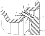
- FIG. 4 is an extract of a cross-sectional view of a vehicle wheel, connected by means of connection arrangement according to a fourth design variant with the countersunk bolt according to FIG. 3 and an elongated sleeve with a peripheral area widened in a tapered manner in a recessed arrangement.
- FIG. 4 a is a detailed view X of the connecting point of the vehicle wheel according to FIG. 4 without the connection element.
- FIG. 5 is an extract of a cross-sectional view of an example vehicle wheel, connected by means of a connection arrangement according to a fifth design variant with the countersunk bolt and the elongated sleeve according to FIG. 3 and a perforated disc.
- FIG. 6 is an extract of a cross-sectional view of an example vehicle wheel, connected by means of a flat-head bolt with a piston-like shaft section.
- FIG. 1 shows a section of a vehicle wheel in accordance with the prior art with a wheel rim 1 and a wheel spider 2 , which are connected by means of a connecting element (flat-head screw) 3 in the area of the rim base in the transition zone to the well of the wheel rim 1 .
- the loads arising on the wheel construction are composed, to different and changing proportions, of longitudinal forces (F A ), transverse forces (F Q ) and bending moments (M B ), which are transferred from the wheel disc or from the wheel spider 2 via the individual connecting elements 3 to the rim base of the wheel rim 1 .
- the first embodiment of the present disclosure shows, in FIG. 2 a , a section of a vehicle wheel in accordance with the present disclosure consisting of a wheel rim 1 a with a rim base made from fiber composite material and a wheel spider 2 . 1 made from aluminum.
- connection arrangements in accordance with the present disclosure, arranged distributed around the circumference of the wheel rim 1 a or the wheel spider 2 . 1 and corresponding to the number of spokes, are provided in the area of the rim base in the transition zone to the well; these each comprise a flat-head bolt 3 . 1 as a connecting element and an elongated sleeve 4 with an annular cylindrical shape, each of which occupy a clearance hole 5 of the rim base and an assigned joining channel 6 of the spoke end of the wheel spider 2 .
- the annular cylindrical elongated sleeve 4 extends with a first section across the entire cross section of the rim base and with a second section into the spoke end of the wheel spider 2 . 1 .
- the first section of the elongated sleeve 4 completely occupies the clearance hole 5 of the rim base and is flush with the clearance hole 5 on the rim outer side; on the rim inner side the second section of the elongated sleeve projects beyond the clearance hole 5 , so that the elongated sleeve 4 , in the assembled state, occupies part of the joining channel 6 in the spoke end of the wheel spider 2 . 1 .
- the first section of the elongated sleeve 4 is embedded in a radial extension 7 of the clearance hole 5 designed with the same shape as its (the first section's) outer contour, whereby the second section of the elongated sleeve 4 that projects beyond the rim inner side of the rim base is inserted into a recess 8 of the joining channel 6 of the spoke end of the wheel spider 2 . 1 that corresponds and has the same shape as its (the second section's) outer contour.
- the detail view of FIG. 2 c shows the radial extension 7 of the clearance hole 5 and the recess 8 of the joining channel 6 of FIG. 2 a more clearly by omitting the connecting element 3 and the elongated sleeve 4 of FIG. 2 a.
- the recess 8 of the joining channel 6 is a partial radial extension 8 of the joining channel 6 and extends approximately across a third to a half of the total length of the joining channel.
- the end of the recess 8 forms an axial contact surface for the elongated sleeve 4 that is inserted.
- the flat head of the flat-head bolt 3 . 1 contacts with the rim outer side of the rim base and with the elongated sleeve 4 that ends flush on the rim outer side.
- the shaft of the flat-head bolt 3 . 1 is guided loosely, i.e. at a distance from the inner lateral surface of the elongated sleeve 4 , through the latter.
- a shaft end of the flat-head bolt 3 . 1 projects beyond the end of the elongated sleeve 4 mounted in the recess 6 is inserted, glued in, screwed in, or pressed into the joining channel 6 of the wheel spider 2 . 1 .
- a shaft end of the flat-head bolt 3 . 1 which projects beyond the elongated sleeve 4 mounted in the recess 8 , has a thread which engages with the joining channel 6 of the spoke end of the wheel spider 2 . 1 equipped with an internal thread.
- the flat-head bolt 3 . 1 during operation of the vehicle wheel, essentially transfers only the longitudinal forces F A arising, whilst the elongated sleeve 4 mounted in a form-fit manner essentially absorbs the transverse forces F Q and bending moments M B arising.
- connection is extremely durable and reliable, which guarantees the security of the connection and thereby of the vehicle wheel to a high level.
- the section of the elongated sleeve 4 that extends in the rim base can be glued in the clearance hole 5 of the rim base or sit in the clearance hole 5 of the rim base by means of an interference fit.
- the section of the elongated sleeve 4 that extends into the wheel spider 2 . 1 can be glued into the recess 8 of the joining channel 6 of the wheel spider 2 . 1 or be inserted into the recess 8 by means of an interference fit.
- FIG. 2 b shows, in a second embodiment, the vehicle wheel according to FIG. 2 a with an alternative connection arrangement for attaching the wheel spider 2 . 1 to an example wheel rim 1 b.
- connection arrangements in accordance with the present disclosure comprise, in each case, the flat-head bolt 3 . 1 according to FIG. 2 a as a connecting element combined with an annular cylindrical elongated sleeve 4 . 1 in a shorter design.
- the first section of the elongated sleeve 4 . 1 arranged in the rim base extends, unlike the elongated sleeve 4 according to FIG. 2 a , across only part of the rim base cross section, so that the end of the elongated sleeve 4 . 1 directed towards the rim outer side ends in the rim base.
- the clearance hole 5 of the rim base has a corresponding recess 7 that extends to an appropriately shorter extent for the first section.
- the flat-head bolt 3 . 1 can be arranged countersunk in the rim base.
- the length of the first section of the elongated sleeve 4 . 1 that extends in the rim base is of such dimensions here that the head section that contacts flush with the end of the recess of the rim base and contacts with the elongated sleeve 4 . 1 is flush with the rim outer side.
- the recessed design of the flat-head bolt 3 . 1 facilitates the fitting of a tyre, not shown here, onto the rim base.
- FIG. 3 shows, in a third embodiment, the vehicle wheel according to FIG. 2 a with a further alternative connection arrangement for attaching the wheel spider 2 . 1 to an example wheel rim 1 c.
- connection arrangements in accordance with the present disclosure comprise, in each case, a countersunk bolt 3 . 2 as a connecting element and an elongated sleeve 4 . 2 .
- the elongated sleeve 4 . 2 according to FIG. 3 has, unlike the annular cylindrical elongated sleeve 4 according to FIG. 2 a , in addition to an annual cylindrical area directed towards the rim inner side, a peripheral area widened in a tapered manner directed towards the rim outer side, with a collar-shaped support flange.
- the first section of the elongated sleeve 4 . 2 thus formed that extends across the entire cross section of the rim base is arranged in a radial extension 7 of the clearance hole 5 designed to correspond to the shape of its (the section's) outer contour, whereby the tapered peripheral area of the elongated sleeve 4 . 2 contacts with a chamfered contact face of the recess 7 of the clearance hole 5 and the support flange of the peripheral area of the elongated sleeve 4 . 2 extends across the surface of the rim outer side.
- the countersunk bolt 3 . 2 is guided loosely through the elongated sleeve 4 . 2 , whereby its countersunk head is received by the peripheral area, widened in a tapered manner, of the elongated sleeve 4 . 2 and contacts with a seat surface 9 that corresponds to the countersunk head.
- FIG. 4 shows a fourth embodiment of a vehicle wheel in a similar design to FIG. 3 with a further alternative connection arrangement for attaching the wheel spider 2 . 1 to an example wheel rim 1 d.
- connection arrangements in accordance with the present disclosure comprise, in each case, the countersunk bolt 3 . 2 according to FIG. 3 as a connecting element combined with an elongated sleeve 4 . 3 .
- the elongated sleeve 4 . 3 in accordance with FIG. 4 has, unlike the elongated sleeve 4 . 2 in accordance with FIG. 3 , in addition to the annular cylindrical area directed towards the rim inner side, a peripheral area widened in a tapered manner and thickened and directed towards the rim outer side.
- the first section of the elongated sleeve 4 . 3 that extends across the entire cross section of the rim base is arranged in a radial extension 7 of the clearance hole 5 designed so as to correspond to the shape of its (the section's) outer contour, whereby the tapered peripheral area of the elongated sleeve 4 . 2 contacts with a chamfered contact face of the recess 7 of the clearance hole 5 .
- the peripheral area, widened in a tapered manner and thickened, of the elongated sleeve 4 . 3 is flush with the rim outer side of the rim base.
- the countersunk head of the countersunk bolt 3 . 2 is, in the peripheral area, widened in a tapered manner, of the elongated sleeve 4 . 3 , placed so as to correspond to its seat surface 9 , so that the entire connection arrangement is flush with the rim outer side.
- the attachment surface of the elongated sleeve 4 . 3 to the rim base and the attachment surface of the countersunk head of the bolt 3 . 2 to the elongated sleeve 4 . 3 are increased and hence the surface pressure between the countersunk head of the countersunk bolt 3 . 2 , the elongated sleeve 4 . 3 and the rim base of the wheel rim 1 d is reduced.
- the countersunk bolt 3 . 2 is not shown so as to make things easier to see.
- a contact surface of the countersunk head of the countersunk bolt 3 . 2 facing the seat surface 9 is also designed to have a roughened or corrugated feature 100 .
- FIG. 5 shows, in a fifth embodiment, a vehicle wheel in a similar design to that according to FIG. 3 with a further alternative connection arrangement for attaching the wheel spider 2 . 1 to an example wheel rim 1 e.
- connection arrangements in accordance with the present disclosure comprise, in each case, a countersunk bolt 3 . 2 and an elongated sleeve 4 . 2 as per the design according to the embodiment in FIG. 3 .
- connection arrangement additionally has a perforated disc 10 which surrounds the second section of the elongated sleeve 4 . 2 that protrudes beyond the clearance hole 5 on the rim inner side.
- the perforated disc 10 is, on the rim inner side of the rim base—in each case surrounding a clearance hole 5 —connected to the wheel rim 1 e or, on the attachment side of the spoke ends—in each case surrounding a joining channel 6 —connected to the wheel spider 2 . 1 .
- the perforated disc 10 is, in the final assembly stage of the vehicle wheel, arranged between the contact surfaces of the rim inner side of the rim base and the attachment side of the spoke end of the wheel spider 2 . 1 . It can, through a suitable choice of material and suitable design, be used to change and set the friction conditions between the contact surfaces, in order to further reduce the required preload force of the countersunk bolt 3 . 2 .
- the wheel spider 2 . 1 can be attached, contactless, to the rim base, so that the risk of contact corrosion between the materials of the wheel rim 2 . 1 and the wheel spider 2 . 1 can be minimised and better compatibility of the thermal expansion can be achieved.
- FIG. 6 depicts a section of a vehicle wheel in accordance with the present disclosure, consisting of an example wheel rim if made from aluminum and a wheel spider 2 . 1 made from aluminum.
- the flat-head bolt 3 . 3 has a piston-like shaft section 11 with a smooth surface which directly attaches to the shaft end at the end, which is equipped with a thread for joining in the wheel spider 2 . 1 .
- the piston-like shaft section 11 has, compared with the cross section of the shaft section at the end, a radially widened cross section and extends, in the assembled state, with a first section partially in the rim base and with a second section into the spoke end of the wheel spider 2 . 1 .
- the first section of the piston-like shaft section 11 occupies the clearance hole 5 of the rim base only partially, so that the clearance hole 5 of the rim base has a correspondingly partially constructed radial extension 7 for the first section. Attached to this is a recess for the flat head of the flat-head bolt 3 . 3 .
- the flat-head bolt 3 . 3 is, in the screwed-in state, flush with the rim outer side of the rim base, whereby the flat head is received by the recess envisaged for this and a bottom surface of the recess serves as a seat surface for the flat head.
- the shaft section at the end of the flat-head bolt 3 . 3 brings about, by means of its external thread which engages with the internal thread of the joining channel 6 of the wheel spider 2 . 1 , a force-fit screw connection.
- the first section of the piston-like shaft section 11 sits in a radial extension 7 of the clearance hole 5 that corresponds in shape to its (the section's) outer contour and the second section sits in a recess 8 of the joining channel 6 of the spoke end of the wheel spider 2 that corresponds in shape to its (the section's) outer contour.
- the recess 8 of the joining channel 6 is a partial radial extension 8 of the joining channel 6 .
- the first section of the piston-like shaft section 11 extends, in the screwed-in state of the flat-head bolt 3 . 3 , approximately across half of the total length of the clearance hole 5 whilst the second section extends approximately across a quarter to a third of the total length of the joining channel 6 .
- the transverse forces F Q are, during operation of the vehicle wheel, not transferred via frictional locking between the contact surfaces of the rim base and the wheel spider 2 but primarily through the form-fit connection between the piston-like shaft section 11 and the extension 7 of the clearance hole 5 or the recess 8 of the joining channel 6 .
- the connecting point is thereby, compared with a connection in accordance with the prior art according to FIG. 1 , designed slimmer and at the same time has smaller contact surfaces of the rim inner side of the wheel rim if and the spoke ends of the wheel spider 2 . 1 that contact with the rim inner side.
- this connection Owing to the lower compressive load on the rim base and the spoke ends of the wheel spider 2 . 1 made from aluminum, this connection is also less susceptible to damage and reliable in the long term, which guarantees the security of the connection to a high level.
Landscapes
- Engineering & Computer Science (AREA)
- Mechanical Engineering (AREA)
- Connection Of Plates (AREA)
- Tires In General (AREA)
Abstract
Description
Claims (20)
Applications Claiming Priority (4)
| Application Number | Priority Date | Filing Date | Title |
|---|---|---|---|
| DE102014112980 | 2014-09-09 | ||
| DE102014112980 | 2014-09-09 | ||
| DE102014112980.6 | 2014-09-09 | ||
| PCT/DE2015/100385 WO2016037611A1 (en) | 2014-09-09 | 2015-09-08 | Vehicle wheel comprising a wheel rim and a wheel disc |
Publications (2)
| Publication Number | Publication Date |
|---|---|
| US20170253077A1 US20170253077A1 (en) | 2017-09-07 |
| US10569599B2 true US10569599B2 (en) | 2020-02-25 |
Family
ID=54249269
Family Applications (1)
| Application Number | Title | Priority Date | Filing Date |
|---|---|---|---|
| US15/508,584 Active US10569599B2 (en) | 2014-09-09 | 2015-09-08 | Vehicle wheel comprising a wheel rim and a wheel disc |
Country Status (7)
| Country | Link |
|---|---|
| US (1) | US10569599B2 (en) |
| EP (1) | EP3191313B1 (en) |
| CN (1) | CN106687303B (en) |
| AT (1) | AT17467U1 (en) |
| BR (1) | BR112017003062B1 (en) |
| DE (2) | DE112015004114A5 (en) |
| WO (1) | WO2016037611A1 (en) |
Cited By (1)
| Publication number | Priority date | Publication date | Assignee | Title |
|---|---|---|---|---|
| US20210162804A1 (en) * | 2018-04-20 | 2021-06-03 | ThyssenKrupp Carbon Components GmbH | Multi-part vehicle wheel with a seal |
Families Citing this family (14)
| Publication number | Priority date | Publication date | Assignee | Title |
|---|---|---|---|---|
| DE112015004114A5 (en) | 2014-09-09 | 2017-07-06 | ThyssenKrupp Carbon Components GmbH | VEHICLE WHEEL WITH A WHEEL RIM AND A WHEEL DISC |
| DE202015009949U1 (en) * | 2014-10-31 | 2021-12-08 | Mubea Carbo Tech Gmbh | wheel for a vehicle |
| DE102016214379A1 (en) * | 2016-08-03 | 2018-02-08 | Bayerische Motoren Werke Aktiengesellschaft | Connection of rim and wheel center with a built vehicle wheel |
| JP6681312B2 (en) * | 2016-10-28 | 2020-04-15 | 本田技研工業株式会社 | Vehicle wheel |
| WO2018177901A1 (en) | 2017-03-29 | 2018-10-04 | Mubea Carbo Tech Gmbh | Wheel for a vehicle |
| US11110742B2 (en) * | 2017-09-08 | 2021-09-07 | Superior Industries International, Inc. | Hybrid wheel assembly with attachment pin |
| DE102018128331B3 (en) * | 2018-11-13 | 2019-08-22 | Otto Fuchs - Kommanditgesellschaft - | Multi-piece wheel for a vehicle |
| CN110082133B (en) * | 2019-05-21 | 2024-06-07 | 青岛科技大学 | Tooth-type rim tire acceleration continuous impact device |
| DE102020112462A1 (en) | 2020-05-07 | 2021-11-11 | Munich Composites Gmbh | Aluminum-CFRP sealing for a hybrid rim and method for manufacturing a hybrid rim |
| US11090976B1 (en) | 2020-10-19 | 2021-08-17 | Icon Vehicle Dynamics Llc | Vehicle tire bead retention systems, devices, and methods |
| IT202100017714A1 (en) * | 2021-07-06 | 2023-01-06 | Bucci Composites S P A | RIM FOR SUPPORTING VEHICLE TIRES |
| TWI787052B (en) * | 2022-01-12 | 2022-12-11 | 明安國際企業股份有限公司 | two piece rim |
| US20230322018A1 (en) * | 2022-04-11 | 2023-10-12 | DNA Specialty | Self-sealing Automotive Spoke Wheel Nipple |
| DE102022131998A1 (en) * | 2022-12-02 | 2024-06-13 | Advanced International Multitech Co., Ltd. | Rim with rim body made of fiber composite material and wheel center made of metal |
Citations (33)
| Publication number | Priority date | Publication date | Assignee | Title |
|---|---|---|---|---|
| DE280481C (en) | ||||
| FR436626A (en) | 1911-04-13 | 1912-04-01 | John William Hall | Improvements to removable rims for elastic bandages |
| US1173243A (en) | 1912-03-20 | 1916-02-29 | Universal Rim Company | Vehicle-wheel. |
| GB173257A (en) | 1920-07-28 | 1921-12-28 | Sydney Irwin Prescott | An improved wheel equipment standardising device |
| US1938862A (en) * | 1932-01-02 | 1933-12-12 | Mayo E Roe | Wheel |
| FR1114895A (en) | 1953-09-09 | 1956-04-17 | Dunlop Sa | Device for fixing the wheel rims to the wheel discs |
| GB767953A (en) * | 1953-08-31 | 1957-02-13 | Dunlop Rubber Co | Improved means for attaching wheel rims to wheel discs and the like |
| US2805894A (en) * | 1952-12-09 | 1957-09-10 | Philo G Gilbert | Wheel with spokes in radial tension |
| US2874749A (en) * | 1956-08-03 | 1959-02-24 | Firestone Tire & Rubber Co | Valve for directional change |
| DE7200847U (en) | 1972-01-11 | 1972-05-04 | Albersinger, Georg, 8091 Atteltal | MOTOR VEHICLE WHEEL IN LIGHTWEIGHT CONSTRUCTION WITH HIGH STRENGTH |
| FR2379389A1 (en) | 1977-02-04 | 1978-09-01 | Fischer Ag Georg | TIRE WHEEL FOR HEAVY VEHICLES |
| FR2471291A1 (en) | 1979-12-17 | 1981-06-19 | Dunlop Sa | Composite construction car wheel - has disc and rim joined by light alloy fixing ring |
| DE3243473A1 (en) * | 1982-11-22 | 1984-05-24 | Mannesmann Kronprinz Ag, 5650 Solingen | Attachment element, in particular for connecting a rim and a wheel hub of a vehicle wheel for tubeless tyres |
| JPS59124702U (en) | 1983-02-10 | 1984-08-22 | 井関農機株式会社 | wheel mounting device |
| JPS59195402A (en) * | 1983-04-21 | 1984-11-06 | Mitsubishi Electric Corp | Lightweight wheel using reinforced plastic |
| US4518204A (en) * | 1982-05-10 | 1985-05-21 | Honda Giken Kogyo Kabushiki Kaisha | Wheel for a vehicle |
| JPS60110503A (en) * | 1983-11-21 | 1985-06-17 | Yanagawa Seiki Kk | Method of producing wheel for light vehicle |
| US4679860A (en) * | 1984-12-21 | 1987-07-14 | Honda Giken Kogyo Kabushiki Kaisha | Wheel assembly for vehicle |
| AU661032B2 (en) * | 1991-08-21 | 1995-07-13 | Fm Mattsson Ab | Valve with a roughened valve sealing surface & tool for manufacture thereof |
| CN1223204A (en) | 1997-12-06 | 1999-07-21 | F·波尔希名誉工学博士公司 | Fixing device for car wheel composed of inner and outer wheel rim |
| US6312058B1 (en) | 1999-04-13 | 2001-11-06 | Raymond L. Lupyrypa | Centering the rim of a wheel on its supporting hub |
| DE10105113A1 (en) | 2000-08-14 | 2002-02-28 | Gerd Mueller | Rim, particularly for road vehicle, has rim bed and wheel star, together with screwing arrangement in transition area between them |
| US20040021365A1 (en) | 2002-05-13 | 2004-02-05 | Alan Georgeff | Two-piece vehicle wheel |
| EP1174285B1 (en) | 2000-07-19 | 2005-03-30 | TITAN ITALIA S.p.A. | A varying-track wheel with devices for mutual-positioning of the rim and disc |
| WO2006097856A2 (en) | 2005-03-16 | 2006-09-21 | Dymag Racing Uk Ltd | Vehicle wheel |
| WO2010067383A1 (en) * | 2008-11-24 | 2010-06-17 | Ruotemilano S.R.L. | Wheel for a tubeless tyre |
| US20130234497A1 (en) * | 2012-03-08 | 2013-09-12 | Interco Tire Corporation | Wheel apparatus |
| WO2015090276A1 (en) | 2013-12-18 | 2015-06-25 | ThyssenKrupp Carbon Components GmbH | Method for producing a wheel rim having a rim base, from a fibre composite |
| WO2015090275A1 (en) | 2013-12-18 | 2015-06-25 | ThyssenKrupp Carbon Components GmbH | Wheel comprising a wheel rim and a wheel disk |
| WO2015106760A1 (en) | 2014-01-15 | 2015-07-23 | ThyssenKrupp Carbon Components GmbH | Vehicle wheel having a combination of a wheel rim with rim well made from fibre composite material and a wheel disc |
| WO2016066769A1 (en) | 2014-10-31 | 2016-05-06 | Mubea Carbo Tech Gmbh | Wheel for a vehicle |
| US20170235077A1 (en) | 2002-10-21 | 2017-08-17 | Commscope Technologies Llc | High density panel with rotating tray |
| EP3191313B1 (en) | 2014-09-09 | 2018-05-16 | ThyssenKrupp Carbon Components GmbH | Vehicle wheel comprising a wheel rim and a wheel disc |
Family Cites Families (1)
| Publication number | Priority date | Publication date | Assignee | Title |
|---|---|---|---|---|
| DK2607097T3 (en) * | 2011-12-20 | 2016-01-25 | Titan Italia S P A | Wheels with variable track |
-
2015
- 2015-09-08 DE DE112015004114.1T patent/DE112015004114A5/en not_active Ceased
- 2015-09-08 AT ATGM50121/2019U patent/AT17467U1/en not_active IP Right Cessation
- 2015-09-08 EP EP15774499.6A patent/EP3191313B1/en active Active
- 2015-09-08 BR BR112017003062-4A patent/BR112017003062B1/en not_active IP Right Cessation
- 2015-09-08 CN CN201580048512.8A patent/CN106687303B/en active Active
- 2015-09-08 DE DE202015009723.5U patent/DE202015009723U1/en not_active Expired - Lifetime
- 2015-09-08 US US15/508,584 patent/US10569599B2/en active Active
- 2015-09-08 WO PCT/DE2015/100385 patent/WO2016037611A1/en not_active Ceased
Patent Citations (37)
| Publication number | Priority date | Publication date | Assignee | Title |
|---|---|---|---|---|
| DE280481C (en) | ||||
| FR436626A (en) | 1911-04-13 | 1912-04-01 | John William Hall | Improvements to removable rims for elastic bandages |
| US1173243A (en) | 1912-03-20 | 1916-02-29 | Universal Rim Company | Vehicle-wheel. |
| GB173257A (en) | 1920-07-28 | 1921-12-28 | Sydney Irwin Prescott | An improved wheel equipment standardising device |
| US1938862A (en) * | 1932-01-02 | 1933-12-12 | Mayo E Roe | Wheel |
| US2805894A (en) * | 1952-12-09 | 1957-09-10 | Philo G Gilbert | Wheel with spokes in radial tension |
| GB767953A (en) * | 1953-08-31 | 1957-02-13 | Dunlop Rubber Co | Improved means for attaching wheel rims to wheel discs and the like |
| FR1114895A (en) | 1953-09-09 | 1956-04-17 | Dunlop Sa | Device for fixing the wheel rims to the wheel discs |
| US2874749A (en) * | 1956-08-03 | 1959-02-24 | Firestone Tire & Rubber Co | Valve for directional change |
| DE7200847U (en) | 1972-01-11 | 1972-05-04 | Albersinger, Georg, 8091 Atteltal | MOTOR VEHICLE WHEEL IN LIGHTWEIGHT CONSTRUCTION WITH HIGH STRENGTH |
| FR2379389A1 (en) | 1977-02-04 | 1978-09-01 | Fischer Ag Georg | TIRE WHEEL FOR HEAVY VEHICLES |
| FR2471291A1 (en) | 1979-12-17 | 1981-06-19 | Dunlop Sa | Composite construction car wheel - has disc and rim joined by light alloy fixing ring |
| US4518204A (en) * | 1982-05-10 | 1985-05-21 | Honda Giken Kogyo Kabushiki Kaisha | Wheel for a vehicle |
| DE3243473A1 (en) * | 1982-11-22 | 1984-05-24 | Mannesmann Kronprinz Ag, 5650 Solingen | Attachment element, in particular for connecting a rim and a wheel hub of a vehicle wheel for tubeless tyres |
| JPS59124702U (en) | 1983-02-10 | 1984-08-22 | 井関農機株式会社 | wheel mounting device |
| JPS59195402A (en) * | 1983-04-21 | 1984-11-06 | Mitsubishi Electric Corp | Lightweight wheel using reinforced plastic |
| JPS60110503A (en) * | 1983-11-21 | 1985-06-17 | Yanagawa Seiki Kk | Method of producing wheel for light vehicle |
| US4679860A (en) * | 1984-12-21 | 1987-07-14 | Honda Giken Kogyo Kabushiki Kaisha | Wheel assembly for vehicle |
| AU661032B2 (en) * | 1991-08-21 | 1995-07-13 | Fm Mattsson Ab | Valve with a roughened valve sealing surface & tool for manufacture thereof |
| CN1223204A (en) | 1997-12-06 | 1999-07-21 | F·波尔希名誉工学博士公司 | Fixing device for car wheel composed of inner and outer wheel rim |
| US6312058B1 (en) | 1999-04-13 | 2001-11-06 | Raymond L. Lupyrypa | Centering the rim of a wheel on its supporting hub |
| EP1174285B1 (en) | 2000-07-19 | 2005-03-30 | TITAN ITALIA S.p.A. | A varying-track wheel with devices for mutual-positioning of the rim and disc |
| DE10105113A1 (en) | 2000-08-14 | 2002-02-28 | Gerd Mueller | Rim, particularly for road vehicle, has rim bed and wheel star, together with screwing arrangement in transition area between them |
| US20040021365A1 (en) | 2002-05-13 | 2004-02-05 | Alan Georgeff | Two-piece vehicle wheel |
| US20170235077A1 (en) | 2002-10-21 | 2017-08-17 | Commscope Technologies Llc | High density panel with rotating tray |
| WO2006097856A2 (en) | 2005-03-16 | 2006-09-21 | Dymag Racing Uk Ltd | Vehicle wheel |
| US20080143171A1 (en) | 2005-03-16 | 2008-06-19 | Mike Wilson | Vehicle Wheel |
| EP1858715B1 (en) | 2005-03-16 | 2009-11-25 | Dymag Racing UK Ltd. | Vehicle wheel |
| WO2010067383A1 (en) * | 2008-11-24 | 2010-06-17 | Ruotemilano S.R.L. | Wheel for a tubeless tyre |
| US20130234497A1 (en) * | 2012-03-08 | 2013-09-12 | Interco Tire Corporation | Wheel apparatus |
| WO2015090276A1 (en) | 2013-12-18 | 2015-06-25 | ThyssenKrupp Carbon Components GmbH | Method for producing a wheel rim having a rim base, from a fibre composite |
| WO2015090275A1 (en) | 2013-12-18 | 2015-06-25 | ThyssenKrupp Carbon Components GmbH | Wheel comprising a wheel rim and a wheel disk |
| US20160318335A1 (en) | 2013-12-18 | 2016-11-03 | ThyssenKrupp Carbon Components GmbH | Wheel comprising a wheel rim and a wheel disc |
| WO2015106760A1 (en) | 2014-01-15 | 2015-07-23 | ThyssenKrupp Carbon Components GmbH | Vehicle wheel having a combination of a wheel rim with rim well made from fibre composite material and a wheel disc |
| US20160325582A1 (en) | 2014-01-15 | 2016-11-10 | ThyssenKrupp Carbon Components GmbH | Vehicle wheel having a connection of a wheel rim with rim base made from fiber composite material and a wheel disc |
| EP3191313B1 (en) | 2014-09-09 | 2018-05-16 | ThyssenKrupp Carbon Components GmbH | Vehicle wheel comprising a wheel rim and a wheel disc |
| WO2016066769A1 (en) | 2014-10-31 | 2016-05-06 | Mubea Carbo Tech Gmbh | Wheel for a vehicle |
Cited By (1)
| Publication number | Priority date | Publication date | Assignee | Title |
|---|---|---|---|---|
| US20210162804A1 (en) * | 2018-04-20 | 2021-06-03 | ThyssenKrupp Carbon Components GmbH | Multi-part vehicle wheel with a seal |
Also Published As
| Publication number | Publication date |
|---|---|
| BR112017003062B1 (en) | 2021-03-23 |
| DE112015004114A5 (en) | 2017-07-06 |
| DE202015009723U1 (en) | 2019-07-30 |
| EP3191313A1 (en) | 2017-07-19 |
| AT17467U1 (en) | 2022-05-15 |
| WO2016037611A1 (en) | 2016-03-17 |
| US20170253077A1 (en) | 2017-09-07 |
| EP3191313B1 (en) | 2018-05-16 |
| CN106687303A (en) | 2017-05-17 |
| CN106687303B (en) | 2020-03-17 |
| BR112017003062A2 (en) | 2018-02-27 |
Similar Documents
| Publication | Publication Date | Title |
|---|---|---|
| US10569599B2 (en) | Vehicle wheel comprising a wheel rim and a wheel disc | |
| US20200282766A1 (en) | Vehicle wheel having a connection between a wheel rim and a wheel disc and method for the production thereof | |
| US11346415B2 (en) | Brake disc for a vehicle | |
| US5911425A (en) | Steering knuckle assembly for automotive vehicles | |
| EP2726301B1 (en) | Attachment arrangement for composite wheels | |
| US20130277158A1 (en) | Assembly of a caliper body of a disc brake and hub bracket | |
| CZ298752B6 (en) | Wheel nut and washer assembly | |
| US20140131152A1 (en) | Wheel-mounted brake disks | |
| CN105008732B (en) | Pin Joint Assembly | |
| US9958021B2 (en) | Brake pad retainer for a disc brake | |
| US20170008558A1 (en) | Arrangement for connecting chassis components and wheel carriers for motor vehicles | |
| KR20150064021A (en) | Wheel structure for an automobile | |
| KR101543128B1 (en) | Disc brake device combined parking brake with different materials | |
| US20080213035A1 (en) | Joint and/or Bearing Arrangement | |
| EP3055141B1 (en) | Driven wheel assembly and automotive vehicle equipped with such an assembly | |
| CN202641263U (en) | Spindle head structure | |
| CA2568699A1 (en) | Brake mechanism | |
| WO2016154007A1 (en) | Alternative approaches to mounting the s-cam tube of a vehicle brake assembly | |
| CN102717666B (en) | Axle head structure of trailer | |
| US20070183841A1 (en) | Central joint for a steering triangle of moto vehicles | |
| CN211642370U (en) | Torsion bar type aluminum alloy overturning support structure | |
| US20050109569A1 (en) | Piston for disc brake assembly | |
| KR100251243B1 (en) | The anchor pin in mechanical drum brake | |
| CN211314917U (en) | Connecting structure of brake and torsion beam and vehicle | |
| JP3131903U (en) | Lightweight wheel rim fixed tool set |
Legal Events
| Date | Code | Title | Description |
|---|---|---|---|
| AS | Assignment |
Owner name: THYSSENKRUPP CARBON COMPONENTS GMBH, GERMANY Free format text: ASSIGNMENT OF ASSIGNORS INTEREST;ASSIGNORS:WERNER, JENS;KOEHLER, CHRISTIAN;MAEKE, SANDRO;AND OTHERS;SIGNING DATES FROM 20170116 TO 20170126;REEL/FRAME:041460/0453 |
|
| STPP | Information on status: patent application and granting procedure in general |
Free format text: RESPONSE TO NON-FINAL OFFICE ACTION ENTERED AND FORWARDED TO EXAMINER |
|
| STPP | Information on status: patent application and granting procedure in general |
Free format text: FINAL REJECTION MAILED |
|
| STPP | Information on status: patent application and granting procedure in general |
Free format text: NOTICE OF ALLOWANCE MAILED -- APPLICATION RECEIVED IN OFFICE OF PUBLICATIONS |
|
| STPP | Information on status: patent application and granting procedure in general |
Free format text: NOTICE OF ALLOWANCE MAILED -- APPLICATION RECEIVED IN OFFICE OF PUBLICATIONS |
|
| STPP | Information on status: patent application and granting procedure in general |
Free format text: PUBLICATIONS -- ISSUE FEE PAYMENT VERIFIED |
|
| STCF | Information on status: patent grant |
Free format text: PATENTED CASE |
|
| MAFP | Maintenance fee payment |
Free format text: PAYMENT OF MAINTENANCE FEE, 4TH YEAR, LARGE ENTITY (ORIGINAL EVENT CODE: M1551); ENTITY STATUS OF PATENT OWNER: LARGE ENTITY Year of fee payment: 4 |
|
| AS | Assignment |
Owner name: ACTION COMPOSITES HIGHTECH GMBH, GERMANY Free format text: CHANGE OF NAME;ASSIGNOR:THYSSENKRUPP CARBON COMPONENTS GMBH;REEL/FRAME:069267/0888 Effective date: 20211027 Owner name: ACTION COMPOSITES GMBH, AUSTRIA Free format text: ASSIGNMENT OF ASSIGNORS INTEREST;ASSIGNOR:ACTION COMPOSITES HIGHTECH GMBH;REEL/FRAME:069030/0553 Effective date: 20240724 |