US10561964B2 - Apparatus for dewatering and demineralization of fine particles - Google Patents
Apparatus for dewatering and demineralization of fine particles Download PDFInfo
- Publication number
- US10561964B2 US10561964B2 US15/783,389 US201715783389A US10561964B2 US 10561964 B2 US10561964 B2 US 10561964B2 US 201715783389 A US201715783389 A US 201715783389A US 10561964 B2 US10561964 B2 US 10561964B2
- Authority
- US
- United States
- Prior art keywords
- agglomerates
- hydrophobic
- container
- coal
- particles
- Prior art date
- Legal status (The legal status is an assumption and is not a legal conclusion. Google has not performed a legal analysis and makes no representation as to the accuracy of the status listed.)
- Active
Links
Images


Classifications
-
- B—PERFORMING OPERATIONS; TRANSPORTING
- B01—PHYSICAL OR CHEMICAL PROCESSES OR APPARATUS IN GENERAL
- B01D—SEPARATION
- B01D12/00—Displacing liquid, e.g. from wet solids or from dispersions of liquids or from solids in liquids, by means of another liquid
-
- B—PERFORMING OPERATIONS; TRANSPORTING
- B01—PHYSICAL OR CHEMICAL PROCESSES OR APPARATUS IN GENERAL
- B01F—MIXING, e.g. DISSOLVING, EMULSIFYING OR DISPERSING
- B01F23/00—Mixing according to the phases to be mixed, e.g. dispersing or emulsifying
- B01F23/50—Mixing liquids with solids
-
- B—PERFORMING OPERATIONS; TRANSPORTING
- B01—PHYSICAL OR CHEMICAL PROCESSES OR APPARATUS IN GENERAL
- B01F—MIXING, e.g. DISSOLVING, EMULSIFYING OR DISPERSING
- B01F23/00—Mixing according to the phases to be mixed, e.g. dispersing or emulsifying
- B01F23/50—Mixing liquids with solids
- B01F23/53—Mixing liquids with solids using driven stirrers
-
- B—PERFORMING OPERATIONS; TRANSPORTING
- B01—PHYSICAL OR CHEMICAL PROCESSES OR APPARATUS IN GENERAL
- B01D—SEPARATION
- B01D11/00—Solvent extraction
- B01D11/04—Solvent extraction of solutions which are liquid
- B01D11/0492—Applications, solvents used
-
- B01F11/0071—
-
- B—PERFORMING OPERATIONS; TRANSPORTING
- B01—PHYSICAL OR CHEMICAL PROCESSES OR APPARATUS IN GENERAL
- B01F—MIXING, e.g. DISSOLVING, EMULSIFYING OR DISPERSING
- B01F25/00—Flow mixers; Mixers for falling materials, e.g. solid particles
- B01F25/40—Static mixers
-
- B—PERFORMING OPERATIONS; TRANSPORTING
- B01—PHYSICAL OR CHEMICAL PROCESSES OR APPARATUS IN GENERAL
- B01F—MIXING, e.g. DISSOLVING, EMULSIFYING OR DISPERSING
- B01F25/00—Flow mixers; Mixers for falling materials, e.g. solid particles
- B01F25/40—Static mixers
- B01F25/42—Static mixers in which the mixing is affected by moving the components jointly in changing directions, e.g. in tubes provided with baffles or obstructions
- B01F25/43—Mixing tubes, e.g. wherein the material is moved in a radial or partly reversed direction
- B01F25/431—Straight mixing tubes with baffles or obstructions that do not cause substantial pressure drop; Baffles therefor
- B01F25/4314—Straight mixing tubes with baffles or obstructions that do not cause substantial pressure drop; Baffles therefor with helical baffles
- B01F25/43141—Straight mixing tubes with baffles or obstructions that do not cause substantial pressure drop; Baffles therefor with helical baffles composed of consecutive sections of helical formed elements
-
- B—PERFORMING OPERATIONS; TRANSPORTING
- B01—PHYSICAL OR CHEMICAL PROCESSES OR APPARATUS IN GENERAL
- B01F—MIXING, e.g. DISSOLVING, EMULSIFYING OR DISPERSING
- B01F27/00—Mixers with rotary stirring devices in fixed receptacles; Kneaders
- B01F27/05—Stirrers
- B01F27/11—Stirrers characterised by the configuration of the stirrers
- B01F27/111—Centrifugal stirrers, i.e. stirrers with radial outlets; Stirrers of the turbine type, e.g. with means to guide the flow
- B01F27/1111—Centrifugal stirrers, i.e. stirrers with radial outlets; Stirrers of the turbine type, e.g. with means to guide the flow with a flat disc or with a disc-like element equipped with blades, e.g. Rushton turbine
-
- B—PERFORMING OPERATIONS; TRANSPORTING
- B01—PHYSICAL OR CHEMICAL PROCESSES OR APPARATUS IN GENERAL
- B01F—MIXING, e.g. DISSOLVING, EMULSIFYING OR DISPERSING
- B01F27/00—Mixers with rotary stirring devices in fixed receptacles; Kneaders
- B01F27/80—Mixers with rotary stirring devices in fixed receptacles; Kneaders with stirrers rotating about a substantially vertical axis
- B01F27/81—Mixers with rotary stirring devices in fixed receptacles; Kneaders with stirrers rotating about a substantially vertical axis the stirrers having central axial inflow and substantially radial outflow
-
- B01F3/1221—
-
- B—PERFORMING OPERATIONS; TRANSPORTING
- B01—PHYSICAL OR CHEMICAL PROCESSES OR APPARATUS IN GENERAL
- B01F—MIXING, e.g. DISSOLVING, EMULSIFYING OR DISPERSING
- B01F31/00—Mixers with shaking, oscillating, or vibrating mechanisms
- B01F31/65—Mixers with shaking, oscillating, or vibrating mechanisms the materials to be mixed being directly submitted to a pulsating movement, e.g. by means of an oscillating piston or air column
-
- B01F5/0615—
-
- B01F7/00383—
-
- B01F7/1625—
-
- C—CHEMISTRY; METALLURGY
- C10—PETROLEUM, GAS OR COKE INDUSTRIES; TECHNICAL GASES CONTAINING CARBON MONOXIDE; FUELS; LUBRICANTS; PEAT
- C10L—FUELS NOT OTHERWISE PROVIDED FOR; NATURAL GAS; SYNTHETIC NATURAL GAS OBTAINED BY PROCESSES NOT COVERED BY SUBCLASSES C10G, C10K; LIQUEFIED PETROLEUM GAS; ADDING MATERIALS TO FUELS OR FIRES TO REDUCE SMOKE OR UNDESIRABLE DEPOSITS OR TO FACILITATE SOOT REMOVAL; FIRELIGHTERS
- C10L9/00—Treating solid fuels to improve their combustion
-
- C—CHEMISTRY; METALLURGY
- C10—PETROLEUM, GAS OR COKE INDUSTRIES; TECHNICAL GASES CONTAINING CARBON MONOXIDE; FUELS; LUBRICANTS; PEAT
- C10L—FUELS NOT OTHERWISE PROVIDED FOR; NATURAL GAS; SYNTHETIC NATURAL GAS OBTAINED BY PROCESSES NOT COVERED BY SUBCLASSES C10G, C10K; LIQUEFIED PETROLEUM GAS; ADDING MATERIALS TO FUELS OR FIRES TO REDUCE SMOKE OR UNDESIRABLE DEPOSITS OR TO FACILITATE SOOT REMOVAL; FIRELIGHTERS
- C10L2290/00—Fuel preparation or upgrading, processes or apparatus therefore, comprising specific process steps or apparatus units
- C10L2290/08—Drying or removing water
Definitions
- the instant invention pertains to apparatus and methods for dispersion of agglomerates of hydrophobic particles, e.g. coal and hydrophobic minerals, in a continuous phase of hydrophobic liquid.
- the dispersion dewaters the hydrophobic particles by releasing water droplets trapped in the agglomerates along with the hydrophilic particles dispersed in the droplets.
- Coal is an organic material that is burned to produce heat for power generation and for other industrial and domestic applications. However, it has inclusions of mineral matter, which may contain undesirable elements such as sulfur and mercury. Coal combustion can thus produce large amounts of ash, fugitive dusts, mercury, and SO 2 that may need to be handled properly. Therefore, run-of-mine (ROM) coals are cleaned of the mineral matter before utilization, which also helps increase combustion efficiencies and thereby reduces CO 2 emissions. In general, coarse coal (50 ⁇ 0.15 mm) can be cleaned efficiently by exploiting the specific gravity (SG) differences between the organic matter (coal) and the inorganic mineral matter.
- SG specific gravity
- ROM coal can have a large variability of moisture and maximum particle size.
- the range of particle size spans from coarse coal to finely ground or pulverized coal. Slurries of coarse particles are easier to process and dewater than slurries of fine particles.
- the hydrophobic agglomerates are broken (or destabilized) by a mechanical means to disengage (or liberate) the entrapped water droplets from coal particles.
- the breakage step is carried out in a hydrophobic liquid phase, so that the hydrophobic particles are readily dispersed. If the hydrophobic particles are fully dispersed, most of the water droplets are liberated from coal and fall to the bottom, forming an aqueous phase. When the water droplets are separated from coal in this manner, the hydrophilic mineral matter dispersed in them are also separated from coal.
- HHS hydrophobic-hydrophilic separation
- DbD dewatering by displacement
- E energy required to detach the hydrophobic particles from the oil/water interface
- the hydrophobic liquids are chosen from shorter-chain n-alkanes and alkenes, both unbranched and branched, and cycloalkanes and cycloalkenes, with carbon numbers less than eight.
- These and other hydrophobic liquids such as ligroin (light naphtha), naphtha and petroleum naphtha, and mixtures thereof have contact angles ( ⁇ ) greater than 90°, so that hydrophobic particles can be detached from water/oil interfaces with minimal energy expenditures and readily dispersed in the organic liquids.
- hydrophobic liquids have low viscosities and low boiling points, so that they can be readily recovered by solid/liquid separation (e.g., pressure filtration) and by vaporization/condensation for recycle purpose.
- Liquid carbon dioxide (CO 2 ) is another liquid that can be used as a hydrophobic liquid in the instant invention.
- bitumen is recovered by flotation and the recovered bitumen is further treated by dissolving the froth product in a hydrophobic liquid and subsequently removing entrained water along with the hydrophilic particles such as clay dispersed in the water droplets.
- water-in-oil emulsions are formed, causing a difficulty in dewatering.
- the water-in-oil emulsions are destabilized using various chemicals. It is possible that the method and apparatus disclosed herewith may be used to destabilize the emulsions and facilitate the dewatering process.
- An object of the present invention relates to an apparatus for dispersion of hydrophobic agglomerates and/or water-in-oil-emulsions stabilized by hydrophobic particles in a hydrophobic liquid.
- the hydrophobic agglomerates may comprise coal or other fine particles that are either naturally hydrophobic or hydrophobized using hydrophobizing reagent(s).
- the apparatus comprises a tank or a tubular pipe. Inside the tank or pipe is at least one turbulence-generating mechanism that can break the agglomerates (or emulsions) using an appropriate mechanical device.
- Another object of the present invention relates to methods of using the apparatus to mechanically break the hydrophobic agglomerates and disperse them in a continuous phase of hydrophobic liquid.
- a further object of the present invention relates to methods for making the apparatus for dispersion of hydrophobic agglomerates.
- a still further object of the present invention relates to using the methods and apparatus to destabilize the water-in-oil emulsions stabilized by asphaltenes during the process of dewatering the bitumen recovered by flotation.
- FIG. 1 is a drawing showing an assembly of vibrating screens that are designed to provide adequate mechanical force to break hydrophobic emulsions
- FIG. 2 is a drawing showing the connection between the screen assembly and the motor
- FIG. 3 is a drawing showing the screen assembly and the motor installed in a cylindrical tank
- FIG. 4 is a set of Rushton impellers connected to a rotating shaft that can be used to create a turbulence to break hydrophobic agglomerates and disperse the hydrophobic particles in hydrophobic liquid;
- FIG. 5 is a drawing of the assembly of Rushton impellers installed inside a cylindrical tank
- FIG. 6 is a drawing of the assembly of Wemco-type impeller installed inside a baffled cylindrical tank
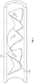
- FIG. 7 is a drawing of an inline mixer, which is designed to generate a turbulence that can be used to break hydrophobic agglomerates while they pass through the tortuous path created by twisted blades;
- FIG. 8 is a drawing of an apparatus, in which hydrophobic agglomerates are broken by the turbulence created by the pulsating fluid moving upward through a packed bed of corrugated materials;
- FIG. 9 is a drawing of an apparatus, in which hydrophobic agglomerates are broken by the turbulence created by the pulsating fluid moving upward and down repeatedly through a ragging material located on a screen in the same manner as a pulsating jig used for solid/solid separation in the minerals and coal industry.
- the present invention relates to apparatus for destabilizing hydrophobic agglomerates and dispersing hydrophobic fine particles in a hydrophobic liquid.
- the apparatus comprises a tank or tubular container. Inside the container is placed a turbulence generating mechanism that can provide sufficient energy to break (or destabilize) the agglomerates and disperse the particles in a hydrophobic liquid.
- the turbulence-generating mechanisms include, but are not limited to, i) at least one vibrating mesh screen whose center is attached to a shaft, ii) at least one dynamic impeller, iii) at least one static and dynamic in-line mixer, iv) a pneumatic or mechanical pulsating mechanism that can reciprocate the suspension of hydrophobic agglomerates through the tortuous path created by a bed of packed materials, v) a pneumatic or mechanical pulsating mechanism that can reciprocate the suspension of hydrophobic agglomerates through a bed of particles located on a screen, and vi) a sonicator to create sufficient mechanical force to break hydrophobic agglomerates.
- the shaft 106 may be a cylindrical metal rod.
- the attachment of each of the screens 102 or 104 to the shaft 106 may be by a collar 108 .
- the collar 108 fits around the shaft and may be attached to the shaft by a suitable fastener, such as crews, bolts, clips, etc.
- the method for attachment is not important as long as the screen 102 or 104 is secured to the shaft 106 without allowing for sliding of the screen along the length of the shaft during operation.
- the shaft is connected to a reciprocating motor 204 designed to vibrate the mesh screen in a vertical direction as shown in FIGS. 2 and 3 .
- the screen 102 or 104 is preferably stabilized by a ring 110 at its outer circumference.
- the ring may be made of a metal or a polymer and provides sufficient rigidity to hold the screen flat without collapsing during operation.
- the screen may also be further stabilized by at least one supporting rod 112 , extending from the center of the screen to the ring 110 .
- the supporting rod 112 is rigidly attached to the ring 110 to further stabilize the screen.
- FIG. 1 shows rods intersecting at about 90 degrees, any number of rods may be used to stabilize the screen.
- the rods are spaced evenly around the screen to provide an even support of the screen.
- the supporting rod may be made of a metal or a polymer as long as it provides sufficient rigidity to hold the screen flat without collapsing during operation.
- One end of the shaft is connected to a reciprocating motor 204 of FIGS. 2 and 3 .
- a reciprocating motor 204 of FIGS. 2 and 3 Referring to FIG. 2 , there is shown a mechanism for such attachment.
- the shaft 106 is connected to the shaft 202 of the reciprocating motor 204 , e.g. by an adaptor 206 which rigidly and coaxially attaches the shaft 106 to the motor shaft 202 .
- the connection allows for the translation of the reciprocating motion of the motor shaft 204 to be transferred to the shaft 106 .
- a supporting structure 208 is provided to further stabilize the connection between the motor 204 and the shaft 106 .
- the support structure preferably contains a clamp 210 , a flange 212 , and connecting rods 214 connecting the clamp 210 to the flange 212 .
- the clamp 210 fits around and clamps to the body of the motor 204 .
- the flange 212 is essentially a flat disc-shape assembly with a hole in the middle of the disc where the shaft 106 passes through. The hole allows the shaft 106 to fit therethrough but not so tightly that it impedes the vertical motion of the shaft.
- the hole allows the shaft 106 to move in a direction approximately vertical to the plane of the disc, but prevents motion of the shaft in a direction approximately parallel to the plane of the disc.
- the clamp 210 and the flange 212 are rigidly connected to each other by the connecting rods 214 to form a rigid structure to support the connection between the motor 204 and the shaft 106 to allow for a smooth transfer of the reciprocating motion to the shaft 106 .
- FIG. 3 shows the screen assembly installed in a tank.
- the shaft and screens are then placed inside the tank 305 .
- the placement is such that the ring 110 is not in contact with the side of the tank 305 .
- the ring has a largest diameter that is, about 70-95% of the inner diameter of the tank, preferably about 80-90%.
- a vapor tight boot 303 and seal 304 may be installed around the shaft outside the reactor.
- agglomeration resulting from mixing of fine hydrophobic particles in an aqueous media with a hydrophobic liquid
- a hydrophobic liquid are added to the tank 305 through an inlet pipe 306 .
- the motor 204 is then activated to allow the shaft 106 , and thereby the screens 102 and 104 , to move in a reciprocating motion. That allows the screens 102 and 104 to vibrate vertically within the tank 305 to assist in the dispersion of the coal agglomerates.
- the hydrophobic liquid used in the tank 305 can be, but is not limited to, n-alkanes (such as pentane, hexane, and heptanes), n-alkenes, unbranched and branched cycloalkanes and cycloalkenes with carbon numbers of less than eight, ligroin, naphtha, petroleum naptha, petroleum ether, liquid carbon dioxide, and mixtures thereof.
- the preferred hydrophobic liquid is pentane.
- the screen aperture should be larger than the size of the largest particles constituting the hydrophobic agglomerates, so that dispersed particles can freely pass through the screens mesh.
- the strength of screen vibrational as measured by the acceleration due to vibration normalized by gravitational acceleration, is in the range of 0.5 to 10 for the case of coal agglomerates formed by particles of less than 44 ⁇ m. The vibrational strength is given as
- A the amplitude of vibration in meter
- ⁇ the angular velocity of the motor creating vibration
- f the frequency of vibration in Hz
- g the gravitational acceleration. If ⁇ is too small, agglomerates do not break, while if ⁇ is too large, water-in-oil emulsions are formed.
- FIGS. 4 and 5 Another embodiment of the present invention is shown FIGS. 4 and 5 , which essentially depicts a Rushton turbine as an example of using a dynamic impeller as a turbulence generating mechanism.
- the device contains of a flat disk 422 mounted on a rotating shaft 421 by means of ring clamps 424 with flat blades 423 vertically mounted.
- the shaft-impeller assembly is rotated by an electrical motor 502 .
- a vapor tight boot 503 and seal 504 may be installed around the shaft outside the reactor.
- FIG. 5 shows a Rushton impeller installed in a cylindrical tank 505 .
- a hydrophobic agglomerate is fed to a feed pipe 506 to allow for the agglomerates to be broken by the turbulence created by the impellers, fixed onto the shaft 421 . Breakage of the agglomerates disperses hydrophobic particles in the hydrophobic liquid phase 511 , while at the same time releasing (or liberating) the small droplets of water that have been trapped in between the hydrophobic particles constituting the agglomerates.
- the hydrophobic particle-in-hydrophobic liquid dispersion 511 overflows into a discharge box 507 to be removed from the tank 505 , while the liberated water droplets fall by gravity to form an aqueous phase 509 at the bottom, forming a water-hydrophobic liquid phase boundary 510 .
- the hydrophilic mineral matter such as clay is also removed.
- the device described above is capable of simultaneously removing both water and mineral matter from fine particles.
- the separation process described for this embodiment is essentially the same as for the vibrating screen embodiment ( FIGS. 1-3 ), except that Ruston impellers are used instead of vibrating screens.
- FIG. 6 shows another embodiment of the present invention in which coal agglomerates are fed into a cylindrical vessel 608 .
- the vessel is shown equipped with 4 baffle plates 601 situated near the oil/water interface 600 between the hydrophobic oil phase 603 and the water phase 604 located at the bottom of vessel 608 .
- the impeller 602 is a six-blade radial flow impeller of the same shape as the Wemco®-type flotation machine marketed by FLSmidth, and is coupled to a rotating shaft 606 that rotates the impeller 602 to create turbulence in the middle of the vessel 608 rather than near the vessel wall.
- the de-agglomerated hydrophobic coal particles in suspension are recycled via the outlet depicted at 607 , while the de-entrained water droplets and mineral matter dispersed therein are separated as underflow from the bottom of the vessel 608 beneath the baffles 601 .
- FIG. 7 shows a further embodiment of the present invention which is an in-line static mixer.
- the in-line static mixer is designed to create turbulence while hydrophobic agglomerates move through a pipe 702 .
- the degree of turbulence is controlled by varying the number and shape of the mixing elements 704 installed in the pipe and the fluid velocity.
- This embodiment essentially contains a pipe 702 which has mixing elements 704 installed within the pipe.
- the mixing elements 704 may have different shapes and designs to create turbulence as the fluid containing the agglomerates passes through the pipe.
- the turbulence is sufficient to disperse or break up the agglomerates to release the trapped water and associated hydrophilic minerals.
- FIG. 8 shows an additional embodiment of the present invention, in which hydrophobic agglomerates are broken up by pulsating them through the tortuous path in between the packing materials placed in a tank or column.
- a feed is introduced through a port 800 into the device 801 , which is filled with hydrophobic liquid 802 and packing materials 803 .
- a pulse of compressed air is injected through a top port 809 on the top to push the level 807 of the hydrophobic liquid inside the centrally located tubing 804 downward, which in turn pushes the liquid level 805 outside the tubing 804 upward.
- the pulse stroke stops the liquid level 807 in the tubing 804 is restored, while the liquid level 805 in the outer portion is lowered.
- the pulse and stop cycle moves the agglomerates up and down through the tortuous path in between the packing materials 803 , causing the hydrophobic agglomerates or the water-in-hydrophobic liquid emulsion to break-up and the individual hydrophobic particles to be dispersed in the hydrophobic liquid.
- the hydrophobic particles fully dispersed in the hydrophobic liquid are removed through the discharge port 811 , while the water droplets released from the agglomerates and the hydrophobic mineral matter dispersed in the water fall to the bottom and are discharged through the bottom port 815 of the device.
- the efficiency of the unit is controlled by pulse-and-stop cycle, residence time, and packing materials.
- FIG. 9 shows another embodiment of the present invention in which the coal agglomerates are fed into a pulsating jig vessel 908 .
- Hydrophilic quartz particles (ragging) 904 are packed atop a screen mesh 903 disposed in the interior of the vessel 908 .
- the aperture of the screen mesh is smaller than the size of the particles 904 such that the particles 904 are unable to pass through the screen mesh and remain dispersed in the hydrophobic oil phase 901 while de-entrained water and mineral matter coalesce on the surface of the particles 904 forming droplets.
- a modified diaphragm pump 906 provides the pulsion and suction (jigging) cycles that force the agglomerates through the tortuous path between the packed quartz particles, liberating the entrained water and mineral matter, while the de-agglomerated hydrophobic coal particles in suspension are recycled via the outlet depicted at 907 .
- the devices disclosed in the instant invention may also be used to first agglomerate the mineral fines using a hydrophobic liquid and subsequently disperse them in a hydrophobic liquid in the same manner as described for coal fines.
- coal samples used in the examples shown below were freshly generated aqueous slurries rather than those that had already been deposited in fine coal impoundments.
- Three different types of coal fines were tested; 100 mesh ⁇ 0 (or 0.15 mm ⁇ 0) flotation feeds, overflows from 6-inch diameter de-sliming cyclones, and effluents from clean coal dewatering centrifuges (screen-bowl).
- the latter two samples consisted of coal and high-clay mineral fines of ⁇ 44 ⁇ m dispersed in water, with solids contents in the range of 3 to 10% solids. All coal samples were used as received.
- hydrophobic agglomerates were then placed in a laboratory-scale device containing a sufficient volume of n-pentane. A mechanical force was applied to break the agglomerates and subsequently disperse the hydrophobic (or coal) particles in a hydrophobic liquid (n-pentane). The mechanical forces were created by means of vibrating screen mesh, dynamic mixer, sonicator, and a pulsating jig. As hydrophobic agglomerates were broken (or destabilized), entrapped water droplets were liberated from coal and settled to the bottom of the device along with the hydrophilic mineral matter dispersed in the water droplets.
- coal-in-pentane dispersion were allowed to overflow into a beaker, while the water and mineral matter settled to the bottom.
- the coal-in-pentane dispersion recovered in the beaker was subjected to solid-liquid separation, and the coal was subsequently analyzed for moisture and ash contents.
- the device equipped with a set of vibrating mesh screens ( FIGS. 1, 2, and 3 ) was also tested at a proof-of-concept (POC) scale continuous operation.
- POC proof-of-concept
- four to five 55-gallon drums of coal slurry were fed to the POC unit while collecting both the clean coal and reject streams.
- the former was analyzed for ash and moisture contents, while the latter for ash content.
- Table 2 shows the results obtained with two different 100 mesh ⁇ 0 (or 0.15 mm ⁇ 0) flotation feeds, one from Pennsylvania and the other from southern West Virginia.
- the agglomeration products were dispersed in n-pentane in a laboratory-scale device equipped with two vibrating mesh screens, as depicted in FIG. 3 .
- the vibration strengths employed were in the range of 0.8 to 10, as calculated using Eq. [2]
- With the Pennsylvania coal the ash content was reduced from 44.9% in the feed to 3.4% in the clean coal product with 1.6% moisture.
- With the southern West Virginia coal the feed ash was reduced from 52.6% to 3.6% with 1.0% moisture. Both the ash and moisture contents were substantially lower than obtainable by flotation or oil agglomeration processes.
- the main reason for the superior results was the removal of the water droplets and the mineral matter entrapped within the hydrophobic agglomerate structure.
- the amount of energy required to break the agglomerates was small as the driving force for the agglomeration was hydrophobic force, which is a weak force.
- HHS hydrophobic-hydrophilic separation
- deslimed flotation products are dewatered using screen-bowl centrifuges.
- the centrifuges are designed to remove part of the 44 ⁇ m ⁇ 0 particles to improve dewatering. Still the moistures are typically in the range of 18 to 25% depending on coal type and particle size distribution.
- the screen-bowl effluents are discarded to impoundments.
- three different screen-bowl effluents were subjected to laboratory HHS tests using a device equipped with vibrating mesh screens ( FIG. 3 ).
- the ash contents of the feeds were low as they were essentially clean coal products.
- low-ash and low-moisture clean coal products were obtained with over 96% combustible recoveries.
- Table 6 shows the POC-scale continuous test results obtained on three different fine coal slurries.
- the throughput of the POC test unit ranged from 50 to 100 lb/hr, depending on the solids content and particle size of the particles in feed slurry.
- the first example represents the results obtained on an effluent from a clean coal centrifuge (screen-bowl).
- the solids content of the feed slurry was 3.8% solids (or 96.2% water), and the feed coal assayed 7.0% ash.
- the POC unit produced a clean coal assaying 2.1% ash, 4.0% moisture, and 14,123 Btu/lb. Despite the relatively low reject ash, the combustible recovery of the POC-scale test was 97% by weight.
- the second and third examples given in Table 6 represent the POC-scale test results obtained on the ultrafine waste coals (de-sliming cyclone overflows) heading toward impoundments. Both the southwest Virginia and northern West Virginia coals were clayey metallurgical coals in dilute suspensions (7.3 and 3.8% solids) with >50% ash. After a single pass through the POC unit, clean coal products assaying 2.4 and 3.4% ash with 6.1 and 8.5% moisture, respectively, were obtained.
- the device used in these examples was equipped with vibrating screen meshes to create a grid turbulence that can be used to break the hydrophobic agglomerates (or destabilize the water-in-pentane emulsions) and disperse the individual coal particles in a hydrophobic liquid (n-pentane).
- Rushton impellers shown in FIGS. 4 and 5 were used to mechanically break the coal agglomerates formed in a kitchen blender in the presence of a small amount of n-pentane.
- the coal sample was a ⁇ 44 ⁇ m ⁇ 0 classifying cyclone overflow assaying 53.6% ash, destined to a fine coal impoundment.
- the coal agglomerates formed after a low-shear agitation were fed to a laboratory-scale device equipped with two layers of Rushton impellers as shown in FIG. 5 .
- the impellers were agitated at tip speeds in the range of 30 to 60 ft/min, which was sufficient to break the agglomerates and keep the particles suspended in n-pentane.
- coal-in-pentane suspensions were allowed to overflow continuously into a beaker, while the liberated water droplets and mineral matter dispersed in them fell to the bottom.
- the clean coal and reject products were analyzed for moisture and ash contents, and the results are presented in Table 7.
- the ash and moisture contents of the clean coal products varied in the ranges of 1.7 to 12.5 and 2.6 to 5.3%, respectively.
- Table 8 shows the results obtained with a laboratory-scale device equipped with an ultrasonic probe (Qsonica, Model-Q700) to break hydrophobic agglomerates. It shows the test results obtained on southern West Virginia and Pennsylvania coals. Both were ultrafine screen-bowl effluents. Each test was run continuously at a vibrational frequency of 20 kHz for 15 to 20 minutes before taking samples. As shown, very low-ash and low-moisture products were obtained using the device, with high reject ashes and combustible recoveries.
- hydrophobic agglomerates were produced from a cyclone overflow sample assaying 54.2% ash (dry) and 94% water as received from a bituminous coal preparation plant.
- Coal agglomerates were fed to a cylindrical vessel of 3-inch diameter.
- the vessel was equipped with four identical 0.25 ⁇ 2.5-inch baffle plates located 1-inch above the floor of the vessel.
- the vessel was filled with water and pentane (hydrophobic oil) and allowed to form a distinct oil/water interface at 0.5-inch from the vessel floor.
- the vessel was equipped with one (or more) six-blade radial flow impeller with a diameter of 2-inch, which was connected to a rotating shaft. The tests were conducted with the impeller positioned at the center of the baffled zone of the vessel, as shown in FIG. 6 .
- the impeller described above was of the same shape as the Wemco flotation machine marketed by FLSmidth.
- the impeller was chosen to create a turbulence in the middle of the vessel rather than near the vessel wall.
- Tests were conducted at 450-850 rpm, which was sufficient to destabilize the hydrophobic agglomerates and to allow the de-agglomerated particles in suspension.
- the coal-in-pentane suspension free of water droplets were allowed to overflow, while the water droplets setting at the bottom of the vessel along with the mineral matter dispersed in them. Additional hydrophobic-oil was added during the tests to facilitate the overflow of the coal-in-pentane suspension.
- coal-in-pentane suspension was subjected to filtration at 2-4 bars of air pressure, which produced essentially dry coal with small amounts of mineral matter as shown in Table 6. As shown, the clean coal products assayed 2.7-3.1% ash and 1.4-2.9% moisture. The organic matter (or coal) recovery and mineral matter rejections were consistently >96% and >97%, respectively.
- the coal agglomerates formed using pentane as agglomerant was fed to a laboratory-scale pulsating jig shown in FIG. 9 .
- Quartz particles of 2-6 mm size were placed on the screen, whose aperture was smaller than the particles, so that the particles stays in the hydrophobic liquid phase while they move up and down following the pulsion and suction cycles of the jigging motion.
- the screen mesh panel was located close to the oil-water interface.
- the pulsion and suction (or jigging) cycles were generated by modifying a diaphragm pump.
- the pump was sealed at one end, while the other end was connected to the water-phase in the glass column.
- the jig was operated at 3-6 Hz and 4-7 mm strokes.
- the turbulence created in the jig destabilized the hydrophobic agglomerates and allowed the coal particles to be fully dispersed in the oil-phase, while liberating the entrapped water.
- the liberated water droplets collide with the hydrophilic quartz particles, they tend to stay on the hydrophilic surface and increase the probability of coalescence, causing the droplet size to grow.
Landscapes
- Chemical & Material Sciences (AREA)
- Chemical Kinetics & Catalysis (AREA)
- Dispersion Chemistry (AREA)
- Organic Chemistry (AREA)
- Combustion & Propulsion (AREA)
- Oil, Petroleum & Natural Gas (AREA)
- Engineering & Computer Science (AREA)
- Liquid Carbonaceous Fuels (AREA)
- Production Of Liquid Hydrocarbon Mixture For Refining Petroleum (AREA)
- Solid Fuels And Fuel-Associated Substances (AREA)
- Colloid Chemistry (AREA)
- Solid-Sorbent Or Filter-Aiding Compositions (AREA)
- Extraction Or Liquid Replacement (AREA)
- Removal Of Floating Material (AREA)
Priority Applications (2)
| Application Number | Priority Date | Filing Date | Title |
|---|---|---|---|
| US15/783,389 US10561964B2 (en) | 2015-04-13 | 2017-10-13 | Apparatus for dewatering and demineralization of fine particles |
| US16/793,726 US11752451B2 (en) | 2015-04-13 | 2020-02-18 | Method for dewatering and demineralization of fine particles |
Applications Claiming Priority (3)
| Application Number | Priority Date | Filing Date | Title |
|---|---|---|---|
| US201562146655P | 2015-04-13 | 2015-04-13 | |
| PCT/US2016/027327 WO2016168325A1 (en) | 2015-04-13 | 2016-04-13 | Apparatus for dewatering and demineralization of fine particles |
| US15/783,389 US10561964B2 (en) | 2015-04-13 | 2017-10-13 | Apparatus for dewatering and demineralization of fine particles |
Related Parent Applications (1)
| Application Number | Title | Priority Date | Filing Date |
|---|---|---|---|
| PCT/US2016/027327 Continuation WO2016168325A1 (en) | 2015-04-13 | 2016-04-13 | Apparatus for dewatering and demineralization of fine particles |
Related Child Applications (1)
| Application Number | Title | Priority Date | Filing Date |
|---|---|---|---|
| US16/793,726 Division US11752451B2 (en) | 2015-04-13 | 2020-02-18 | Method for dewatering and demineralization of fine particles |
Publications (2)
| Publication Number | Publication Date |
|---|---|
| US20180036651A1 US20180036651A1 (en) | 2018-02-08 |
| US10561964B2 true US10561964B2 (en) | 2020-02-18 |
Family
ID=57127193
Family Applications (2)
| Application Number | Title | Priority Date | Filing Date |
|---|---|---|---|
| US15/783,389 Active US10561964B2 (en) | 2015-04-13 | 2017-10-13 | Apparatus for dewatering and demineralization of fine particles |
| US16/793,726 Active US11752451B2 (en) | 2015-04-13 | 2020-02-18 | Method for dewatering and demineralization of fine particles |
Family Applications After (1)
| Application Number | Title | Priority Date | Filing Date |
|---|---|---|---|
| US16/793,726 Active US11752451B2 (en) | 2015-04-13 | 2020-02-18 | Method for dewatering and demineralization of fine particles |
Country Status (7)
| Country | Link |
|---|---|
| US (2) | US10561964B2 (ru) |
| AU (3) | AU2016248111A1 (ru) |
| CA (1) | CA2982558A1 (ru) |
| CL (1) | CL2017002584A1 (ru) |
| RU (1) | RU2736757C2 (ru) |
| WO (1) | WO2016168325A1 (ru) |
| ZA (1) | ZA201707628B (ru) |
Cited By (1)
| Publication number | Priority date | Publication date | Assignee | Title |
|---|---|---|---|---|
| US11752451B2 (en) | 2015-04-13 | 2023-09-12 | Virginia Tech Intellectual Properties, Inc. | Method for dewatering and demineralization of fine particles |
Families Citing this family (2)
| Publication number | Priority date | Publication date | Assignee | Title |
|---|---|---|---|---|
| CN110935193A (zh) * | 2019-11-22 | 2020-03-31 | 重庆邮电大学 | 一种西药成分萃取装置 |
| CN111249956A (zh) * | 2020-03-20 | 2020-06-09 | 福州大学 | 立式型炭物料加湿搅拌机及其工作方法 |
Citations (10)
| Publication number | Priority date | Publication date | Assignee | Title |
|---|---|---|---|---|
| US3601369A (en) | 1969-04-01 | 1971-08-24 | Eugene A Wahl | Apparatus for mixing particulate materials |
| US3647066A (en) | 1969-06-13 | 1972-03-07 | Galigher Co | Flotation machine and system utilizing impeller-type aeration units |
| WO1994022567A1 (en) | 1993-03-29 | 1994-10-13 | British Technology Group Limited | Processing of mixtures by means of pulsations |
| US20010054575A1 (en) * | 1997-08-20 | 2001-12-27 | Kelsey Christopher George | Hutch chamber for jig |
| US6467947B1 (en) | 1997-08-19 | 2002-10-22 | Commonwealth Scientific And Industrial Research Organisation | Method and apparatus for mixing |
| US20030198129A1 (en) | 2002-04-17 | 2003-10-23 | Gary Haughton | Mixing apparatus |
| US7550120B2 (en) | 2005-01-25 | 2009-06-23 | Spx Corporation | Cylindrical mixer-settler apparatus and method |
| US20130111808A1 (en) | 2010-02-01 | 2013-05-09 | Virginia Tech Intellectual Properties ,Inc. | Cleaning and dewatering fine coal |
| US8443981B1 (en) * | 2011-09-07 | 2013-05-21 | Clinton Brent Eldridge | Apparatus for removing heavy material from ore in a water environment and method of use |
| US20130340328A1 (en) | 2010-02-01 | 2013-12-26 | Virginia Tech Intellectual Properties, Inc. | Method of separating and de-watering fine particles |
Family Cites Families (7)
| Publication number | Priority date | Publication date | Assignee | Title |
|---|---|---|---|---|
| FR2402463A1 (fr) | 1977-09-07 | 1979-04-06 | Creusot Loire | Appareil compact pour traitement continu d'un effluent aqueux contenant des hydrocarbures emulsionnes |
| JP3545784B2 (ja) * | 1993-08-12 | 2004-07-21 | 株式会社日清製粉グループ本社 | 被覆準微粒子の製造方法 |
| US5855243A (en) * | 1997-05-23 | 1999-01-05 | Exxon Production Research Company | Oil recovery method using an emulsion |
| JP2003326103A (ja) | 2002-05-13 | 2003-11-18 | Yamaha Motor Co Ltd | 油水分離装置 |
| CN102639219B (zh) * | 2009-08-04 | 2016-03-09 | 索理思科技开曼公司 | 用于乳化油和水的设备、系统和方法 |
| CN203408648U (zh) * | 2013-07-12 | 2014-01-29 | 上海森松混合技术工程装备有限公司 | 一种高效剪切刀式搅拌器 |
| CA2982558A1 (en) | 2015-04-13 | 2016-10-20 | Virginia Tech Intellectual Properties, Inc. | Apparatus for dewatering and demineralization of fine particles |
-
2016
- 2016-04-13 CA CA2982558A patent/CA2982558A1/en active Pending
- 2016-04-13 WO PCT/US2016/027327 patent/WO2016168325A1/en active Application Filing
- 2016-04-13 RU RU2017139264A patent/RU2736757C2/ru active
- 2016-04-13 AU AU2016248111A patent/AU2016248111A1/en not_active Abandoned
-
2017
- 2017-10-12 CL CL2017002584A patent/CL2017002584A1/es unknown
- 2017-10-13 US US15/783,389 patent/US10561964B2/en active Active
- 2017-11-10 ZA ZA2017/07628A patent/ZA201707628B/en unknown
-
2020
- 2020-02-18 US US16/793,726 patent/US11752451B2/en active Active
-
2021
- 2021-07-14 AU AU2021205056A patent/AU2021205056A1/en not_active Abandoned
-
2023
- 2023-06-30 AU AU2023204213A patent/AU2023204213A1/en active Pending
Patent Citations (11)
| Publication number | Priority date | Publication date | Assignee | Title |
|---|---|---|---|---|
| US3601369A (en) | 1969-04-01 | 1971-08-24 | Eugene A Wahl | Apparatus for mixing particulate materials |
| US3647066A (en) | 1969-06-13 | 1972-03-07 | Galigher Co | Flotation machine and system utilizing impeller-type aeration units |
| WO1994022567A1 (en) | 1993-03-29 | 1994-10-13 | British Technology Group Limited | Processing of mixtures by means of pulsations |
| US6467947B1 (en) | 1997-08-19 | 2002-10-22 | Commonwealth Scientific And Industrial Research Organisation | Method and apparatus for mixing |
| US20010054575A1 (en) * | 1997-08-20 | 2001-12-27 | Kelsey Christopher George | Hutch chamber for jig |
| US20030198129A1 (en) | 2002-04-17 | 2003-10-23 | Gary Haughton | Mixing apparatus |
| US7550120B2 (en) | 2005-01-25 | 2009-06-23 | Spx Corporation | Cylindrical mixer-settler apparatus and method |
| US20130111808A1 (en) | 2010-02-01 | 2013-05-09 | Virginia Tech Intellectual Properties ,Inc. | Cleaning and dewatering fine coal |
| US20130340328A1 (en) | 2010-02-01 | 2013-12-26 | Virginia Tech Intellectual Properties, Inc. | Method of separating and de-watering fine particles |
| US9789492B2 (en) | 2010-02-01 | 2017-10-17 | Virginia Tech Intellectual Properties, Inc. | Cleaning and dewatering fine coal |
| US8443981B1 (en) * | 2011-09-07 | 2013-05-21 | Clinton Brent Eldridge | Apparatus for removing heavy material from ore in a water environment and method of use |
Non-Patent Citations (2)
| Title |
|---|
| Chilean Office Action dated Jan. 14, 2019 in corresponding Chilean Patent Application No. 2584-2017. |
| International Search Report and Written Opinion dated Jul. 15, 2016 in corresponding PCT Patent Application No. PCT/US16/27327. |
Cited By (1)
| Publication number | Priority date | Publication date | Assignee | Title |
|---|---|---|---|---|
| US11752451B2 (en) | 2015-04-13 | 2023-09-12 | Virginia Tech Intellectual Properties, Inc. | Method for dewatering and demineralization of fine particles |
Also Published As
| Publication number | Publication date |
|---|---|
| RU2017139264A3 (ru) | 2019-08-07 |
| US20200179821A1 (en) | 2020-06-11 |
| RU2736757C2 (ru) | 2020-11-19 |
| RU2017139264A (ru) | 2019-05-13 |
| WO2016168325A1 (en) | 2016-10-20 |
| AU2016248111A1 (en) | 2017-11-02 |
| US11752451B2 (en) | 2023-09-12 |
| CL2017002584A1 (es) | 2018-03-16 |
| AU2021205056A1 (en) | 2021-08-12 |
| AU2023204213A1 (en) | 2023-08-10 |
| ZA201707628B (en) | 2021-05-26 |
| US20180036651A1 (en) | 2018-02-08 |
| CA2982558A1 (en) | 2016-10-20 |
Similar Documents
| Publication | Publication Date | Title |
|---|---|---|
| US11752451B2 (en) | Method for dewatering and demineralization of fine particles | |
| AU2016247055B2 (en) | Cleaning and dewatering fine coal | |
| US10913912B2 (en) | Methods for separating and dewatering fine particles | |
| US8951422B2 (en) | Apparatus and method for separation of phases in a multiphase flow | |
| AU2011261162B2 (en) | Method and apparatus for separating low density particles from feed slurries | |
| RU2644181C2 (ru) | Способы разделения и обезвоживания тонкодисперсных частиц | |
| CN201240883Y (zh) | 油水分离装置 | |
| CA2684083C (en) | Skim tank configurations and methods | |
| US11331676B2 (en) | Cleaning and dewatering fine coal | |
| Yoon et al. | Cleaning and dewatering fine coal | |
| Smith | Methods of improving oil agglomeration | |
| Gupta | Development of a novel fine coal cleaning and dewatering technology | |
| NO132531B (ru) |
Legal Events
| Date | Code | Title | Description |
|---|---|---|---|
| FEPP | Fee payment procedure |
Free format text: ENTITY STATUS SET TO UNDISCOUNTED (ORIGINAL EVENT CODE: BIG.); ENTITY STATUS OF PATENT OWNER: SMALL ENTITY |
|
| FEPP | Fee payment procedure |
Free format text: ENTITY STATUS SET TO SMALL (ORIGINAL EVENT CODE: SMAL); ENTITY STATUS OF PATENT OWNER: SMALL ENTITY |
|
| STPP | Information on status: patent application and granting procedure in general |
Free format text: RESPONSE TO NON-FINAL OFFICE ACTION ENTERED AND FORWARDED TO EXAMINER |
|
| STPP | Information on status: patent application and granting procedure in general |
Free format text: NON FINAL ACTION MAILED |
|
| STPP | Information on status: patent application and granting procedure in general |
Free format text: NOTICE OF ALLOWANCE MAILED -- APPLICATION RECEIVED IN OFFICE OF PUBLICATIONS |
|
| STPP | Information on status: patent application and granting procedure in general |
Free format text: NOTICE OF ALLOWANCE MAILED -- APPLICATION RECEIVED IN OFFICE OF PUBLICATIONS |
|
| STPP | Information on status: patent application and granting procedure in general |
Free format text: PUBLICATIONS -- ISSUE FEE PAYMENT VERIFIED |
|
| STCF | Information on status: patent grant |
Free format text: PATENTED CASE |
|
| AS | Assignment |
Owner name: VIRGINIA POLYTECHNIC INSTITUTE AND STATE UNIVERSITY, VIRGINIA Free format text: ASSIGNMENT OF ASSIGNORS INTEREST;ASSIGNORS:YOON, ROE-HOAN;LUTTRELL, GERALD H.;GUPTA, NIKHIL;REEL/FRAME:051814/0011 Effective date: 20160420 Owner name: VIRGINIA TECH INTELLECTUAL PROPERTIES, INC., VIRGINIA Free format text: ASSIGNMENT OF ASSIGNORS INTEREST;ASSIGNOR:VIRGINIA POLYTECHNIC INSTITUTE AND STATE UNIVERSITY;REEL/FRAME:051814/0155 Effective date: 20161128 |
|
| MAFP | Maintenance fee payment |
Free format text: PAYMENT OF MAINTENANCE FEE, 4TH YR, SMALL ENTITY (ORIGINAL EVENT CODE: M2551); ENTITY STATUS OF PATENT OWNER: SMALL ENTITY Year of fee payment: 4 |